EP4461663B1 - Élément verseur pour un emballage composite et emballage composite doté d'un élément verseur - Google Patents
Élément verseur pour un emballage composite et emballage composite doté d'un élément verseur Download PDFInfo
- Publication number
- EP4461663B1 EP4461663B1 EP23172725.6A EP23172725A EP4461663B1 EP 4461663 B1 EP4461663 B1 EP 4461663B1 EP 23172725 A EP23172725 A EP 23172725A EP 4461663 B1 EP4461663 B1 EP 4461663B1
- Authority
- EP
- European Patent Office
- Prior art keywords
- pouring
- level section
- cutting element
- section
- package
- Prior art date
- Legal status (The legal status is an assumption and is not a legal conclusion. Google has not performed a legal analysis and makes no representation as to the accuracy of the status listed.)
- Active
Links
Images

Classifications
-
- B—PERFORMING OPERATIONS; TRANSPORTING
- B65—CONVEYING; PACKING; STORING; HANDLING THIN OR FILAMENTARY MATERIAL
- B65D—CONTAINERS FOR STORAGE OR TRANSPORT OF ARTICLES OR MATERIALS, e.g. BAGS, BARRELS, BOTTLES, BOXES, CANS, CARTONS, CRATES, DRUMS, JARS, TANKS, HOPPERS, FORWARDING CONTAINERS; ACCESSORIES, CLOSURES, OR FITTINGS THEREFOR; PACKAGING ELEMENTS; PACKAGES
- B65D5/00—Rigid or semi-rigid containers of polygonal cross-section, e.g. boxes, cartons or trays, formed by folding or erecting one or more blanks made of paper
- B65D5/42—Details of containers or of foldable or erectable container blanks
- B65D5/72—Contents-dispensing means
- B65D5/74—Spouts
- B65D5/746—Spouts formed separately from the container
- B65D5/747—Spouts formed separately from the container with means for piercing or cutting the container wall or a membrane connected to said wall
- B65D5/748—Spouts formed separately from the container with means for piercing or cutting the container wall or a membrane connected to said wall a major part of the container wall or membrane being left inside the container after the opening
-
- B—PERFORMING OPERATIONS; TRANSPORTING
- B65—CONVEYING; PACKING; STORING; HANDLING THIN OR FILAMENTARY MATERIAL
- B65D—CONTAINERS FOR STORAGE OR TRANSPORT OF ARTICLES OR MATERIALS, e.g. BAGS, BARRELS, BOTTLES, BOXES, CANS, CARTONS, CRATES, DRUMS, JARS, TANKS, HOPPERS, FORWARDING CONTAINERS; ACCESSORIES, CLOSURES, OR FITTINGS THEREFOR; PACKAGING ELEMENTS; PACKAGES
- B65D5/00—Rigid or semi-rigid containers of polygonal cross-section, e.g. boxes, cartons or trays, formed by folding or erecting one or more blanks made of paper
- B65D5/40—Rigid or semi-rigid containers of polygonal cross-section, e.g. boxes, cartons or trays, formed by folding or erecting one or more blanks made of paper specially constructed to contain liquids
Definitions
- a pouring element for a composite package in particular for a beverage carton for liquid foods, comprising: a base body comprising a fastening flange and a pouring tube with a central axis, a cutting element arranged and moveably guided in the pouring tube, first guide means formed in the pouring tube, and second guide means formed on the cutting element, wherein the first and second guide means cooperate correspondingly, wherein the first guide means is a rib being arranged on the inner wall of the pouring tube, wherein the rib is divided into three roughly identical circumferential sections, wherein each of these circumferential sections comprises a high level section for the initial position of the cutting element, a low level section for the end position of the cutting element, and an intermediate level section for predominantly rotational movement of the cutting element, wherein each high level section is connected to an intermediate level section by a first transitional section, and wherein each intermediate level section is connected to a low level section by a second transitional section.
- beverage cartons for example consist of various packaging materials such as paper and plastics, which when joined over their solid area and printed form a packaging laminate.
- the layer structure can vary depending on requirements, so that for example for aseptic contents a barrier layer is additionally incorporated in order to achieve a good barrier effect against gases and light, for example a barrier layer made from aluminium, polyamide (PA) or ethylene vinyl alcohol (EVOH).
- PA polyamide
- EVOH ethylene vinyl alcohol
- the laminate is also cut to the size of the packaging during its production and in this way so called packaging pre-cut parts (blanks) are formed.
- the packaging laminate is also supplied as an endless material (rolled goods) and is only later cut to size.
- Typical contents are mainly liquid foods, such as for example beverages, soups or yoghurt. Thickened, pasty or lumpy products or the like are also conceivable.
- Packagings of the aforementioned type are sometimes also provided with pouring elements. Apart from allowing a controlled pouring, these as a rule also provide for the possibility of re-closure. Not infrequently, and principally with aseptic use, a first-opening function for the packaging is also envisaged. In this case the previously gastight sealed packaging is opened for the first time. This can take place for example by means of a ring pull or a pull tab or also by means of a piercing and/or cutting device. Such piercing and/or cutting devices are often formed as sleeve-shaped cutting elements (e.g. cutting rings), which are coupled for example to the screw cap via drive means, so that by means of the rotational actuation of the screw cap the packaging is simultaneously cut open.
- sleeve-shaped cutting elements e.g. cutting rings
- European patents EP 3 464 089 B1 and EP 3 464 090 B1 disclose three-part pouring elements. While these pouring elements have many advantages, it has been found that under certain circumstances (in particular with smaller pouring elements), these pouring elements are not able to consistently cut and remove the layers of the packaging material completely from the pouring tube.
- the object of the invention is to improve the opening performance of the pouring element.
- the pouring element for a composite package, in particular for a beverage carton for liquid foods.
- the pouring element comprises a base body with a fastening flange and a pouring tube with a central axis.
- the fastening flange can be attached to a package and the pouring tube serves to pour out the content of the package through the pouring tube.
- the pouring element also comprises a cutting element that is arranged and moveably guided in the pouring tube.
- the cutting element can be formed as a circular cutting ring.
- the pouring element comprises first guide means that are formed in the pouring tube, and second guide means that are formed on the cutting element, wherein the first and second guide means cooperate correspondingly.
- the first guide means is a rib being arranged on the inner wall of the pouring tube.
- the rib can be formed as one continuous rib or, alternatively, consist of several parts which are separated from each other (e.g. separated by recesses).
- the rib is arranged over the whole circumference of the inner wall of the pouring tube.
- the rib is divided into three roughly identical circumferential sections. If the rib consists of three separate parts, it is preferred that each of the three circumferential sections corresponds to one of the three parts of the rib. Each of these three sections could preferably extend over about 120°.
- Each of these circumferential sections comprises a high level section for the initial position of the cutting element, a low level section for the end position of the cutting element, and an intermediate level section for predominantly or even pure rotational movement of the cutting element.
- the high level section is connected to an intermediate level section by a first transitional section, and each intermediate level section is connected to a low level section by a second transitional section.
- each intermediate level section extends around the central axis over an extension angle which is at least 35°.
- each intermediate level section extends around the central axis over an extension angle which is at least 40°, preferably at least 45°.
- An increased extension angle of the intermediate level section facilitates an extended rotation of the cutting element.
- the cutting element can rotate further and consequently, provide a better opening performance.
- An extended cutter rotation in particular an extended intermediate level section, can be achieved by making other sections of the rib shorter / more compact, such as the low level section and/or the second transitional section.
- the cutting element can be held up in three places (one per circumferential section), there exists a possibility that it may tilt slightly during opening and thus block further movement. This danger is mostly negligible during the transitional sections; the cutting element is following a predominantly piercing path.
- the forces while turning in the intermediate level section may be considerably higher as the package weakening needs to be slowly torn open (over a large turning angle). Said forces may also be higher near the frontmost of the cutting teeth which leads to an uneven force distribution across these three points. Although this uneven force distribution cannot be truly eliminated, the extended cutter rotation tries to mitigate these problems by spreading them out over a longer path with more constant stabilization. This guarantees that the intended cutting portion is severed before the guide means reach the second transitional section.
- the extension angle of the intermediate level section extends over at least 60%, in particular over at least 70%, preferably over at least 75% of the sum of the extension angle of the low level section, the extension angle of the second transitional section and the extension angle of the intermediate level section.
- the rib is divided into three roughly identical circumferential sections, each of them preferably extending over about one third of the circumference, thus about 120°.
- the three circumferential sections may be slightly smaller than 120° so that there is a gap between adjacent circumferential sections or the three circumferential sections may be slightly bigger than 120° so that adjacent circumferential sections partly overlap. In order to achieve an improved opening performance, a large proportion of this circumferential section shall be used for a pure rotation of the cutting element.
- the extension angle of the intermediate level section shall therefore at least extend over at least 60%, 70% or 75% of sum of three adjoining angles, namely the extension angle of the low level section, the extension angle of the second transitional section and the extension angle of the intermediate level section.
- the second transitional section is tilted at a tilting angle that is smaller than 10°, preferably between 2° and 6° relative to the vertical/axial direction.
- a very steep (almost vertical) shape of the second transitional section has the effect that the second transitional section requires less space in the circumferential direction which provides more space for the intermediate level section and therefore for the pure rotational movement of the cutting element.
- the change from pure rotation to the piercing transitional path is problematic when thinking of a cutting element blockage and needs to be kept as short as possible, i.e. a sharp angle of nearly 90° between intermediate level section and second transitional section which translates into the aforementioned tilting angle smaller than 10°.
- the second guide means is formed by three pairs of cams that are distributed over the circumference of the cutting element.
- the first guide means is a rib with three roughly identical circumferential sections
- the second guide means can cooperate especially well with the first guide means if they also comprise three roughly identical parts such as three pairs of cams which are distributed evenly over the circumference of the cutting element.
- Such pairs of cams enclose the rib of the first guide means.
- a pair of cams has the advantage that the first cam can be arranged above the rim, whereas the second cam can be arranged below the rim so that the cutting element can be guided precisely. This provides an additional restriction on the degrees of freedom of the forced guidance, so that this becomes more reliable and accurate.
- the high level section of the rib has a recessed area with a decreased rib depth.
- the rib depth is measured in the radial direction of the pouring tube.
- a reduced radial depth of the rib simplifies the assembly process of the cutting element and the base body, reduces forces and the likelihood of either the rib or the cams breaking off.
- a reduced radial rib depth makes smaller and cheaper cams possible.
- a closure cap is connected to the base body and that the cutting element can be driven by drive flanks formed on the closure cap that act on drive elements arranged on the cutting element.
- the drive flanks have a thickness which is at least 0,6 mm, preferably between 0,6 mm and 0,8 mm.
- a closure cap makes possible the re-closure of a composite package whose contents have been partially consumed. The first-opening rotational movement can be used to drive the cutting element at the same time ("single action"). If the drive is realized over drive flanks (on the cap) and webs (on the cutting element), a particularly advantageous coupling is provided. In order to transfer the required torque without excessive bending, the drive flanks shall have a minimum thickness in the indicated range.
- the two drive flanks are arranged on the closure cap and that two corresponding drive elements are arranged on the cutting element.
- the number of drive flanks on the closure cap shall correspond with the number of drive elements on the cutting element.
- an optimal compromise is obtained between material consumption and drive function.
- two drive elements allow for more design space and thus optimized elements which can still transmit the required amount of force for opening.
- more than two such elements have proven to be suboptimal since the elements needed to be designed more weakly as a trade-off when trying to fit them into such a closure.
- one of the drive elements is arranged in an area which is free of any severing means.
- one of the drive elements shall be arranged in a circumferential stretch which is free of any severing means/teeth, for example between the last tooth and the first tooth.
- This arrangement of one of the drive elements improves the force transmission from the closure cap to the cutting element and then to the severing means / teeth. The main forces are generated close to the front/first tooth which increases the stability of the cutting element guidance and lowers the chances of tilting the ring. This also improves the rigidity of the area with the recess.
- the invention is also defined by a composite package, in particular a beverage carton for liquid food stuffs, with a package gable panel suitable for accommodating a pouring element, wherein the package gable panel has a local package material weakness, and a pouring element according to one of claims 1 to 12 is positioned and permanently connected so that during the first actuation of the pouring element the cutting element is movable towards the package material weakness, thereby opening the composite package so that it is ready for emptying the contents.
- the pouring element and composite package should always closely match to one another. Thus, an exact positioning on a package gable panel provided for this purpose is of decisive importance.
- the pouring element must remain connected to the composite package, and on the other hand the cutting element should engage exactly in the package material weakness created for this purpose.
- the cutting element cuts open an arc-shaped line in the packaging material weakness where the remaining part between start and end point of said arc keeps the mostly severed part of the packaging material weakness attached to the rest of the package. The thusly attached part will be pushed aside by the cutting element when it continues moving towards the second transitional section and into the low level section. Only this procedure allows a complete opening of the package, which is then ready for the emptying of the contents.
- the packaging material weakening is formed as a prelaminated hole.
- Such a special preparation of the package material is suitable specifically for the opening by a material-optimised and production-optimised pouring element, since the piercing does not have to take place through the full material of the composite package but only through some of the layers.
- the cutting element may comprise a recess with two shoulders that are inclined upwards relative to a circumferential curve at a shoulder angle that is at least 15°, preferably at least 25°.
- the cutting element comprises a recess that is free of any severing means/teeth and comprises two shoulders that are inclined upwards (relative to a circumferential direction) at a shoulder angle.
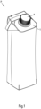
- the embodiment illustrated in Fig. 1 of a composite package P according to the invention shows the package P as a beverage carton.
- the composite package P consists of a package material, which forms a package laminate from a series of flat joined-together materials: polymer layers are laminated on both sides of a carton carrier layer and an additional barrier layer (here: aluminium) screens the product in the composite package P against undesired environmental influences (light, oxygen).
- the composite package P has in the edge region a package gable panel 1, to which a pouring element A according to the invention is applied and permanently attached.
- a package material weakness region - here covered by the pouring element A - is cut and the composite package P is thereby opened for the first time, which is then ready for emptying the contents.
- This weakness region in the illustrated and thus preferred exemplary embodiment is implemented as an over-coated perforation, which is formed during production: for this, a hole is punched out of the carton carrier layer, so that after it has been coated over a local weakness is produced. This still guarantees the usual barrier functions (water, gas and possibly light).
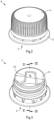
- Fig. 2 shows the pouring element A according to the invention, whose parts individually produced in an injection moulding method are installed (assembled) ready for use: a base body 2, a - in this case concealed - cutting element 3 (illustrated in Fig. 7 ) which is formed as a circular cutting ring and a closure cap 4.
- the pouring element A that is now functionally ready for use is then applied via a fastening flange 5 to the composite package P and permanently connected by, e.g. means of a hot-melt adhesive.
- the closure cap 4 When the closure cap 4 is actuated for the first time by the consumer, the unscrewing movement of the closure cap 4 is transferred to the cutting element 3 guided in the base body 2, which cuts the composite package P in the region of the weakness. The product can then be poured out through the thus created opening.
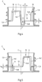
- the base body 2 is illustrated in Fig. 3 , which in addition to the fastening flange 5 also consists of a pouring tube 6 that has an inner diameter D i6 .
- the cutting element 3 is arranged in the pouring tube 6 and is forcibly guided over first guide means 7 formed on the inner wall of the pouring tube 6.
- first guide means 7 is formed by a rib 9.
- Figs. 4 and Fig. 5 show two differing view points of the vertically sectioned halves of the base body 2 with the respective inner wall of the pouring tube 6, on which the outline of the projecting rib 9 is visible.
- the pouring tube 6 is shaped roughly cylindrically and has a central axis C.
- the rib 9 has in the upper region a high level section 10, which forms the guide section for the initial position of the cutting element 3. If the cutting element 3 is now caused to move, it follows the first guide means 7 and is moved from the high level section 10 over a section of variable pitch to a low level section 11, where the end position of the cutting element 3 is reached.
- the actual opening process of the composite package P takes place between the high level section 10 and low level section 11.
- the severing means 12 formed at the end on the cutting element 3 pierce and cut (see Fig. 7 ) the composite package P in the region of the over-coated perforation.
- an intermediate level section 13 is formed between the high level section 10 and low level section 11 on the rib 9, which produces a pure rotation (without axial movement along the central axis C) of the cutting element 3, whereby over this region the severing means 12 cut instead of pierce the over-coated perforation.
- the intermediate level section 13 has a height H 13 which is measured along a direction parallel to the central axis C of the pouring tube 6.
- the first guide means 7 or the rib 9 also comprises a first transitional section 14A, a section transitional section 14B and a third transitional section 14C.
- the first transitional section 14A connects the high level section 10 with the intermediate level section 13 and has a very steep direction (almost vertical / parallel to the central axis C). As a result of this shape, the first transitional section 14A moves the cutting element 3 downwards mainly in the axial direction ("piercing movement").
- the second transitional section 14B connects the intermediate level section 13 with the low level section 11 and also has a very steep shape (almost vertical / parallel to the central axis C).
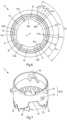
- Fig. 6 shows the base body 2 of Fig. 3 in a top view.
- the high level section 10 extends over an extension angle ⁇ 10 which is about 45°
- the intermediate level section 13 extends over an extension angle ⁇ 13 which is about 45°
- the low level section 11 extends over an extension angle ⁇ 11 which is about 10°.
- the high level section 10 of the rib 9 has a recessed area 10A with a decreased rib depth (measured in the radial direction).
- the recess 21 should span an angle (from the first to the last severing means) smaller than a circumferential section CS to enable a reliable opening.
- the recess 21 has also the effect that the package can be emptied completely because the recess 21 can act like an outlet which allows the content of the package to get over the circular cutting element 3 into the pouring tube 6 when the package is held upside down.
- Fig. 9 shows the closure cap 4 as an individual part.
- Drive flanks 18 are formed on the inner surface of the cover surface, which act on drive elements 19, which are formed as webs, projecting on the inside of the cutting element 3 (see Fig. 7 ).
- the closure cap 4 is thereby coupled to the cutting element 3 and the desired force and torque transmission can take place.
- the drive flanks 18 have a thickness 20 which is at least 0,6 mm, preferable between 0,6 mm and 0,8 mm.
Landscapes
- Engineering & Computer Science (AREA)
- Mechanical Engineering (AREA)
- Cartons (AREA)
- Closures For Containers (AREA)
Claims (14)
- Élément verseur (A) pour un emballage composite, en particulier pour une brique à boisson pour aliments liquides, comprenant :- un corps de base (2) comprenant une bride de fixation (5) et un tube verseur (6) avec un axe central (C),- un élément de coupe (3) agencé et guidé de manière mobile dans le tube verseur (6),- un premier moyen de guidage (7) formé dans le tube verseur (6), et- un second moyen de guidage (8) formé sur l'élément de coupe (3),- dans lequel les premier et second moyens de guidage (7, 8) coopèrent en conséquence,- dans lequel le premier moyen de guidage (7) est une nervure (9) agencée sur la paroi interne du tube verseur (6),- dans lequel la nervure (9) est divisée en trois sections circonférentielles (CS) à peu près identiques,- dans lequel chacune de ces sections circonférentielles (CS) comprend une section de niveau haut (10) pour la position initiale de l'élément de coupe (3), une section de niveau bas (11) pour la position finale de l'élément de coupe (3), et une section de niveau intermédiaire (13) pour le mouvement principalement rotatif de l'élément de coupe (3),- dans lequel chaque section de niveau haut (10) est reliée à une section de niveau intermédiaire (13) par une première section de transition (14A), et- dans lequel chaque section de niveau intermédiaire (13) est reliée à une section de niveau bas (11) par une seconde section de transition (14B),caractérisé en ce que
chaque section de niveau intermédiaire (13) s'étend autour de l'axe central (C) sur un angle d'extension (α13) qui est d'au moins 35°. - Élément verseur (A) selon la revendication 1,
caractérisé en ce que
chaque section de niveau intermédiaire (13) s'étend autour de l'axe central (C) sur un angle d'extension (α13) qui est d'au moins 40°, de préférence d'au moins 45°. - Élément verseur (A) selon la revendication 1 ou la revendication 2,
caractérisé en ce que
l'angle d'extension (α13) de la section de niveau intermédiaire (13) s'étend sur au moins 60 %, en particulier sur au moins 70 %, de préférence sur au moins 75 % de la somme de l'angle d'extension (α11) de la section de niveau bas (11), de l'angle d'extension (α14B) de la seconde section de transition (14B) et de l'angle d'extension (α13) de la section de niveau intermédiaire (13). - Élément verseur (A) selon l'une des revendications 1 à 3,
caractérisé en ce que
la seconde section de transition (14B) est inclinée à un angle d'inclinaison (β) inférieur à 10°, de préférence compris entre 2° et 6° par rapport à la direction verticale/axiale. - Élément verseur (A) selon l'une des revendications 1 à 4,
caractérisé en ce que
le second moyen de guidage (8) est formé par trois paires (16) de cames (15) qui sont réparties sur la circonférence de l'élément de coupe (3). - Élément verseur (A) selon la revendication 5,
caractérisé en ce que
chaque paire (16) de cames (15) présente un écartement entre les deux cames (15) qui présente une hauteur (H15) comprise entre 1,5 fois et 3 fois, notamment entre 1,5 fois et 2,5 fois la hauteur (H13) de la section de niveau intermédiaire (13). - Élément verseur (A) selon l'une des revendications 1 à 6,
caractérisé en ce que
la section de niveau haut (10) de la nervure (9) présente une zone en retrait (10A) avec une profondeur de nervure réduite. - Élément verseur (A) selon l'une des revendications 1 à 7,
caractérisé en ce que
le tube verseur (6) présente un diamètre interne (Di6) inférieur à 20 mm, de préférence compris entre 15 mm et 18 mm. - Élément verseur (A) selon l'une des revendications 1 à 8,
caractérisé en ce que
un capuchon de fermeture (4) est relié au corps de base (2) et l'élément de coupe (3) peut être entraîné par des flancs d'entraînement (18) formés sur le capuchon de fermeture (4) qui agissent sur des éléments d'entraînement (19) agencés sur l'élément de coupe (3). - Élément verseur (A) selon la revendication 9,
caractérisé en ce que
les flancs d'entraînement (18) présentent une épaisseur (20) d'au moins 0,6 mm, de préférence comprise entre 0,6 mm et 0,8 mm. - Élément verseur (A) selon la revendication 9 ou 10,
caractérisé en ce que
deux flancs d'entraînement (18) sont agencés sur le capuchon de fermeture (4) et que deux éléments d'entraînement (19) correspondants sont agencés sur l'élément de coupe (3). - Élément verseur (A) selon la revendication 11,
caractérisé en ce que
l'un des éléments d'entraînement (19) est agencé dans une zone qui est exempte de tout moyen de sectionnement (12). - Emballage composite (P), en particulier une brique à boisson pour denrées alimentaires liquides, avec un panneau à pignon d'emballage (1) adapté au logement d'un élément verseur (A), dans lequel le panneau à pignon d'emballage (1) présente une faiblesse locale du matériau d'emballage, et un élément verseur (A) selon l'une des revendications 1 à 12 est positionné et relié de manière permanente de sorte que lors de la première activation de l'élément verseur (A), l'élément de coupe (3) est mobile en direction de la faiblesse du matériau d'emballage, ouvrant ainsi l'emballage composite (P) afin qu'il soit prêt pour vider le contenu.
- Emballage composite (P) selon la revendication 13,
caractérisé en ce que
l'affaiblissement du matériau d'emballage est formé sous la forme d'un trou prélaminé.
Priority Applications (4)
| Application Number | Priority Date | Filing Date | Title |
|---|---|---|---|
| EP23172725.6A EP4461663B1 (fr) | 2023-05-11 | 2023-05-11 | Élément verseur pour un emballage composite et emballage composite doté d'un élément verseur |
| KR1020257037529A KR20250176976A (ko) | 2023-05-11 | 2024-04-19 | 복합 패키지용 주입 부재 및 주입 부재가 있는 복합 패키지 |
| PCT/EP2024/060679 WO2024231073A1 (fr) | 2023-05-11 | 2024-04-19 | Élément verseur pour un emballage composite et emballage composite doté d'un élément verseur |
| CN202480029323.5A CN121100095A (zh) | 2023-05-11 | 2024-04-19 | 用于复合包装的倾倒元件和具有倾倒元件的复合包装 |
Applications Claiming Priority (1)
| Application Number | Priority Date | Filing Date | Title |
|---|---|---|---|
| EP23172725.6A EP4461663B1 (fr) | 2023-05-11 | 2023-05-11 | Élément verseur pour un emballage composite et emballage composite doté d'un élément verseur |
Publications (3)
| Publication Number | Publication Date |
|---|---|
| EP4461663A1 EP4461663A1 (fr) | 2024-11-13 |
| EP4461663C0 EP4461663C0 (fr) | 2025-07-02 |
| EP4461663B1 true EP4461663B1 (fr) | 2025-07-02 |
Family
ID=86332046
Family Applications (1)
| Application Number | Title | Priority Date | Filing Date |
|---|---|---|---|
| EP23172725.6A Active EP4461663B1 (fr) | 2023-05-11 | 2023-05-11 | Élément verseur pour un emballage composite et emballage composite doté d'un élément verseur |
Country Status (4)
| Country | Link |
|---|---|
| EP (1) | EP4461663B1 (fr) |
| KR (1) | KR20250176976A (fr) |
| CN (1) | CN121100095A (fr) |
| WO (1) | WO2024231073A1 (fr) |
Family Cites Families (8)
| Publication number | Priority date | Publication date | Assignee | Title |
|---|---|---|---|---|
| TWI356795B (en) * | 2004-11-15 | 2012-01-21 | Sig Technology Ltd | Flat self-opening closure for combipacks or for co |
| DE102006016113B3 (de) * | 2006-04-04 | 2007-08-23 | Sig Technology Ag | Wiederverschließbares Ausgießelement für Karton/Kunststoff-Verbundpackungen |
| DK2055640T3 (da) * | 2007-11-05 | 2011-04-04 | Tetra Laval Holdings & Finance | Genlukkelig åbningsindretning til emballager til hældbare levnedsmiddelprodukter |
| DE102013101526B4 (de) * | 2013-02-15 | 2018-05-17 | Sig Technology Ag | Vorrichtung zum Öffnen und Wiederverschließen von Lebensmittel enthaltenden Packungen |
| PL3464090T3 (pl) | 2016-05-31 | 2020-11-02 | Sig Technology Ag | Element do wylewania dla opakowania laminatowego oraz opakowanie laminatowe z elementem do wylewania |
| DE102016110047B3 (de) | 2016-05-31 | 2017-05-04 | Sig Technology Ag | Ausgießelement für eine Verbundpackung sowie Verbundpackung mit einem Ausgießelement |
| EP3943408B1 (fr) * | 2020-07-24 | 2023-06-07 | SIG Combibloc Services AG | Élément verseur pourvu de guidage d'élément de coupe de sécurisation |
| DE102021116173B3 (de) * | 2021-06-22 | 2022-03-17 | Bericap Holding Gmbh | Bajonettverschluss |
-
2023
- 2023-05-11 EP EP23172725.6A patent/EP4461663B1/fr active Active
-
2024
- 2024-04-19 KR KR1020257037529A patent/KR20250176976A/ko active Pending
- 2024-04-19 WO PCT/EP2024/060679 patent/WO2024231073A1/fr not_active Ceased
- 2024-04-19 CN CN202480029323.5A patent/CN121100095A/zh active Pending
Also Published As
| Publication number | Publication date |
|---|---|
| KR20250176976A (ko) | 2025-12-22 |
| EP4461663C0 (fr) | 2025-07-02 |
| CN121100095A (zh) | 2025-12-09 |
| EP4461663A1 (fr) | 2024-11-13 |
| WO2024231073A1 (fr) | 2024-11-14 |
Similar Documents
| Publication | Publication Date | Title |
|---|---|---|
| US10597190B2 (en) | Pouring element for a composite packaging and a composite packaging with a pouring element | |
| US7207465B2 (en) | Self-opening closure for composite packagings or for container connection pieces closed by film material | |
| EP1591367B1 (fr) | Boite d'emballage et bouchon de versement | |
| EP2325103B1 (fr) | Fermeture pour conteneur flexible | |
| US10752398B2 (en) | Pouring element for a composite packaging and composite packaging having a pouring element | |
| US7458486B2 (en) | Self-opening closure for composite packagings or for container or bottle nozzles for sealing with film material | |
| EP1056650B1 (fr) | Bec verseur pour en emballage | |
| CN101578221B (zh) | 包括切割套环的塑料封闭装置 | |
| DK2000417T3 (en) | Close to a pourable food product container and process for making it. | |
| US20240150068A1 (en) | Pouring Element and Composite Package With Improved Opening Behaviour | |
| EP2424783B1 (fr) | Raccords pour bec verseur à dent de découpe/rupture | |
| EP1533240B1 (fr) | Dispositif d'ouverture refermable pour conditionnements en feuille scellé de produits alimentaires versables | |
| WO2001064531A9 (fr) | Structure formant un sac distributeur et son orifice verseur | |
| EP4461663B1 (fr) | Élément verseur pour un emballage composite et emballage composite doté d'un élément verseur | |
| AU2005256922B2 (en) | Sheet material formed with a partial depth cut in the form of an open loop and method of forming a curved discontinuity in sheet material | |
| EP4124585B1 (fr) | Dispositif d'ouverture pour un emballage et emballage | |
| EP4428050A1 (fr) | Élément verseur pour un emballage composite avec un élément de coupe pour la première ouverture de l'emballage composite et emballage doté d'un tel élément verseur | |
| US20260116617A1 (en) | Pouring Element for a Composite Package with a Cutting Element for the First Opening of the Composite Package and a Package Provided with Such a Pouring Element | |
| HK1078840B (en) | Self-opening closure for composite packagings or for container or bottle nozzles for sealing with film material |
Legal Events
| Date | Code | Title | Description |
|---|---|---|---|
| PUAI | Public reference made under article 153(3) epc to a published international application that has entered the european phase |
Free format text: ORIGINAL CODE: 0009012 |
|
| STAA | Information on the status of an ep patent application or granted ep patent |
Free format text: STATUS: THE APPLICATION HAS BEEN PUBLISHED |
|
| AK | Designated contracting states |
Kind code of ref document: A1 Designated state(s): AL AT BE BG CH CY CZ DE DK EE ES FI FR GB GR HR HU IE IS IT LI LT LU LV MC ME MK MT NL NO PL PT RO RS SE SI SK SM TR |
|
| STAA | Information on the status of an ep patent application or granted ep patent |
Free format text: STATUS: REQUEST FOR EXAMINATION WAS MADE |
|
| 17P | Request for examination filed |
Effective date: 20250117 |
|
| GRAP | Despatch of communication of intention to grant a patent |
Free format text: ORIGINAL CODE: EPIDOSNIGR1 |
|
| STAA | Information on the status of an ep patent application or granted ep patent |
Free format text: STATUS: GRANT OF PATENT IS INTENDED |
|
| INTG | Intention to grant announced |
Effective date: 20250228 |
|
| GRAS | Grant fee paid |
Free format text: ORIGINAL CODE: EPIDOSNIGR3 |
|
| GRAA | (expected) grant |
Free format text: ORIGINAL CODE: 0009210 |
|
| STAA | Information on the status of an ep patent application or granted ep patent |
Free format text: STATUS: THE PATENT HAS BEEN GRANTED |
|
| AK | Designated contracting states |
Kind code of ref document: B1 Designated state(s): AL AT BE BG CH CY CZ DE DK EE ES FI FR GB GR HR HU IE IS IT LI LT LU LV MC ME MK MT NL NO PL PT RO RS SE SI SK SM TR |
|
| REG | Reference to a national code |
Ref country code: GB Ref legal event code: FG4D |
|
| REG | Reference to a national code |
Ref country code: CH Ref legal event code: EP |
|
| REG | Reference to a national code |
Ref country code: IE Ref legal event code: FG4D |
|
| U01 | Request for unitary effect filed |
Effective date: 20250709 |
|
| U07 | Unitary effect registered |
Designated state(s): AT BE BG DE DK EE FI FR IT LT LU LV MT NL PT RO SE SI Effective date: 20250715 |
|
| PG25 | Lapsed in a contracting state [announced via postgrant information from national office to epo] |
Ref country code: IS Free format text: LAPSE BECAUSE OF FAILURE TO SUBMIT A TRANSLATION OF THE DESCRIPTION OR TO PAY THE FEE WITHIN THE PRESCRIBED TIME-LIMIT Effective date: 20251102 |
|
| PG25 | Lapsed in a contracting state [announced via postgrant information from national office to epo] |
Ref country code: NO Free format text: LAPSE BECAUSE OF FAILURE TO SUBMIT A TRANSLATION OF THE DESCRIPTION OR TO PAY THE FEE WITHIN THE PRESCRIBED TIME-LIMIT Effective date: 20251002 |
|
| PG25 | Lapsed in a contracting state [announced via postgrant information from national office to epo] |
Ref country code: HR Free format text: LAPSE BECAUSE OF FAILURE TO SUBMIT A TRANSLATION OF THE DESCRIPTION OR TO PAY THE FEE WITHIN THE PRESCRIBED TIME-LIMIT Effective date: 20250702 |
|
| PG25 | Lapsed in a contracting state [announced via postgrant information from national office to epo] |
Ref country code: GR Free format text: LAPSE BECAUSE OF FAILURE TO SUBMIT A TRANSLATION OF THE DESCRIPTION OR TO PAY THE FEE WITHIN THE PRESCRIBED TIME-LIMIT Effective date: 20251003 |
|
| PG25 | Lapsed in a contracting state [announced via postgrant information from national office to epo] |
Ref country code: CZ Free format text: LAPSE BECAUSE OF FAILURE TO SUBMIT A TRANSLATION OF THE DESCRIPTION OR TO PAY THE FEE WITHIN THE PRESCRIBED TIME-LIMIT Effective date: 20250702 |
|
| PG25 | Lapsed in a contracting state [announced via postgrant information from national office to epo] |
Ref country code: PL Free format text: LAPSE BECAUSE OF FAILURE TO SUBMIT A TRANSLATION OF THE DESCRIPTION OR TO PAY THE FEE WITHIN THE PRESCRIBED TIME-LIMIT Effective date: 20250702 |
|
| PG25 | Lapsed in a contracting state [announced via postgrant information from national office to epo] |
Ref country code: RS Free format text: LAPSE BECAUSE OF FAILURE TO SUBMIT A TRANSLATION OF THE DESCRIPTION OR TO PAY THE FEE WITHIN THE PRESCRIBED TIME-LIMIT Effective date: 20251002 |
|
| PG25 | Lapsed in a contracting state [announced via postgrant information from national office to epo] |
Ref country code: ES Free format text: LAPSE BECAUSE OF FAILURE TO SUBMIT A TRANSLATION OF THE DESCRIPTION OR TO PAY THE FEE WITHIN THE PRESCRIBED TIME-LIMIT Effective date: 20250702 |
|
| PG25 | Lapsed in a contracting state [announced via postgrant information from national office to epo] |
Ref country code: SM Free format text: LAPSE BECAUSE OF FAILURE TO SUBMIT A TRANSLATION OF THE DESCRIPTION OR TO PAY THE FEE WITHIN THE PRESCRIBED TIME-LIMIT Effective date: 20250702 |
|
| PG25 | Lapsed in a contracting state [announced via postgrant information from national office to epo] |
Ref country code: SK Free format text: LAPSE BECAUSE OF FAILURE TO SUBMIT A TRANSLATION OF THE DESCRIPTION OR TO PAY THE FEE WITHIN THE PRESCRIBED TIME-LIMIT Effective date: 20250702 |