EP4461581A1 - Pre-charge short circuit detection - Google Patents
Pre-charge short circuit detection Download PDFInfo
- Publication number
- EP4461581A1 EP4461581A1 EP24171374.2A EP24171374A EP4461581A1 EP 4461581 A1 EP4461581 A1 EP 4461581A1 EP 24171374 A EP24171374 A EP 24171374A EP 4461581 A1 EP4461581 A1 EP 4461581A1
- Authority
- EP
- European Patent Office
- Prior art keywords
- control circuit
- charge control
- voltage
- battery
- current
- Prior art date
- Legal status (The legal status is an assumption and is not a legal conclusion. Google has not performed a legal analysis and makes no representation as to the accuracy of the status listed.)
- Pending
Links
Images
Classifications
-
- H—ELECTRICITY
- H02—GENERATION; CONVERSION OR DISTRIBUTION OF ELECTRIC POWER
- H02H—EMERGENCY PROTECTIVE CIRCUIT ARRANGEMENTS
- H02H7/00—Emergency protective circuit arrangements specially adapted for specific types of electric machines or apparatus or for sectionalised protection of cable or line systems, and effecting automatic switching in the event of an undesired change from normal working conditions
- H02H7/18—Emergency protective circuit arrangements specially adapted for specific types of electric machines or apparatus or for sectionalised protection of cable or line systems, and effecting automatic switching in the event of an undesired change from normal working conditions for batteries; for accumulators
-
- B—PERFORMING OPERATIONS; TRANSPORTING
- B60—VEHICLES IN GENERAL
- B60L—PROPULSION OF ELECTRICALLY-PROPELLED VEHICLES; SUPPLYING ELECTRIC POWER FOR AUXILIARY EQUIPMENT OF ELECTRICALLY-PROPELLED VEHICLES; ELECTRODYNAMIC BRAKE SYSTEMS FOR VEHICLES IN GENERAL; MAGNETIC SUSPENSION OR LEVITATION FOR VEHICLES; MONITORING OPERATING VARIABLES OF ELECTRICALLY-PROPELLED VEHICLES; ELECTRIC SAFETY DEVICES FOR ELECTRICALLY-PROPELLED VEHICLES
- B60L3/00—Electric devices on electrically-propelled vehicles for safety purposes; Monitoring operating variables, e.g. speed, deceleration or energy consumption
- B60L3/0023—Detecting, eliminating, remedying or compensating for drive train abnormalities, e.g. failures within the drive train
- B60L3/0046—Detecting, eliminating, remedying or compensating for drive train abnormalities, e.g. failures within the drive train relating to electric energy storage systems, e.g. batteries or capacitors
-
- B—PERFORMING OPERATIONS; TRANSPORTING
- B60—VEHICLES IN GENERAL
- B60L—PROPULSION OF ELECTRICALLY-PROPELLED VEHICLES; SUPPLYING ELECTRIC POWER FOR AUXILIARY EQUIPMENT OF ELECTRICALLY-PROPELLED VEHICLES; ELECTRODYNAMIC BRAKE SYSTEMS FOR VEHICLES IN GENERAL; MAGNETIC SUSPENSION OR LEVITATION FOR VEHICLES; MONITORING OPERATING VARIABLES OF ELECTRICALLY-PROPELLED VEHICLES; ELECTRIC SAFETY DEVICES FOR ELECTRICALLY-PROPELLED VEHICLES
- B60L3/00—Electric devices on electrically-propelled vehicles for safety purposes; Monitoring operating variables, e.g. speed, deceleration or energy consumption
- B60L3/04—Cutting off the power supply under fault conditions
-
- B—PERFORMING OPERATIONS; TRANSPORTING
- B60—VEHICLES IN GENERAL
- B60L—PROPULSION OF ELECTRICALLY-PROPELLED VEHICLES; SUPPLYING ELECTRIC POWER FOR AUXILIARY EQUIPMENT OF ELECTRICALLY-PROPELLED VEHICLES; ELECTRODYNAMIC BRAKE SYSTEMS FOR VEHICLES IN GENERAL; MAGNETIC SUSPENSION OR LEVITATION FOR VEHICLES; MONITORING OPERATING VARIABLES OF ELECTRICALLY-PROPELLED VEHICLES; ELECTRIC SAFETY DEVICES FOR ELECTRICALLY-PROPELLED VEHICLES
- B60L3/00—Electric devices on electrically-propelled vehicles for safety purposes; Monitoring operating variables, e.g. speed, deceleration or energy consumption
- B60L3/0092—Electric devices on electrically-propelled vehicles for safety purposes; Monitoring operating variables, e.g. speed, deceleration or energy consumption with use of redundant elements for safety purposes
-
- B—PERFORMING OPERATIONS; TRANSPORTING
- B60—VEHICLES IN GENERAL
- B60L—PROPULSION OF ELECTRICALLY-PROPELLED VEHICLES; SUPPLYING ELECTRIC POWER FOR AUXILIARY EQUIPMENT OF ELECTRICALLY-PROPELLED VEHICLES; ELECTRODYNAMIC BRAKE SYSTEMS FOR VEHICLES IN GENERAL; MAGNETIC SUSPENSION OR LEVITATION FOR VEHICLES; MONITORING OPERATING VARIABLES OF ELECTRICALLY-PROPELLED VEHICLES; ELECTRIC SAFETY DEVICES FOR ELECTRICALLY-PROPELLED VEHICLES
- B60L3/00—Electric devices on electrically-propelled vehicles for safety purposes; Monitoring operating variables, e.g. speed, deceleration or energy consumption
- B60L3/12—Recording operating variables ; Monitoring of operating variables
-
- G—PHYSICS
- G01—MEASURING; TESTING
- G01R—MEASURING ELECTRIC VARIABLES; MEASURING MAGNETIC VARIABLES
- G01R19/00—Arrangements for measuring currents or voltages or for indicating presence or sign thereof
- G01R19/165—Indicating that current or voltage is either above or below a predetermined value or within or outside a predetermined range of values
- G01R19/16566—Circuits and arrangements for comparing voltage or current with one or several thresholds and for indicating the result not covered by subgroups G01R19/16504, G01R19/16528, G01R19/16533
- G01R19/16571—Circuits and arrangements for comparing voltage or current with one or several thresholds and for indicating the result not covered by subgroups G01R19/16504, G01R19/16528, G01R19/16533 comparing AC or DC current with one threshold, e.g. load current, over-current, surge current or fault current
-
- G—PHYSICS
- G01—MEASURING; TESTING
- G01R—MEASURING ELECTRIC VARIABLES; MEASURING MAGNETIC VARIABLES
- G01R31/00—Arrangements for testing electric properties; Arrangements for locating electric faults; Arrangements for electrical testing characterised by what is being tested not provided for elsewhere
- G01R31/50—Testing of electric apparatus, lines, cables or components for short-circuits, continuity, leakage current or incorrect line connections
- G01R31/52—Testing for short-circuits, leakage current or ground faults
-
- H—ELECTRICITY
- H02—GENERATION; CONVERSION OR DISTRIBUTION OF ELECTRIC POWER
- H02H—EMERGENCY PROTECTIVE CIRCUIT ARRANGEMENTS
- H02H1/00—Details of emergency protective circuit arrangements
- H02H1/0007—Details of emergency protective circuit arrangements concerning the detecting means
-
- H—ELECTRICITY
- H02—GENERATION; CONVERSION OR DISTRIBUTION OF ELECTRIC POWER
- H02J—ELECTRIC POWER NETWORKS; CIRCUIT ARRANGEMENTS OR SYSTEMS FOR SUPPLYING OR DISTRIBUTING ELECTRIC POWER; SYSTEMS FOR STORING ELECTRIC ENERGY
- H02J7/00—Circuit arrangements for charging or discharging batteries or for supplying loads from batteries
- H02J7/34—Parallel operation in networks using both storage and other DC sources, e.g. providing buffering
- H02J7/345—Parallel operation in networks using both storage and other DC sources, e.g. providing buffering using capacitors as storage or buffering devices
-
- H—ELECTRICITY
- H02—GENERATION; CONVERSION OR DISTRIBUTION OF ELECTRIC POWER
- H02J—ELECTRIC POWER NETWORKS; CIRCUIT ARRANGEMENTS OR SYSTEMS FOR SUPPLYING OR DISTRIBUTING ELECTRIC POWER; SYSTEMS FOR STORING ELECTRIC ENERGY
- H02J7/00—Circuit arrangements for charging or discharging batteries or for supplying loads from batteries
- H02J7/60—Circuit arrangements for charging or discharging batteries or for supplying loads from batteries including safety or protection arrangements
- H02J7/62—Circuit arrangements for charging or discharging batteries or for supplying loads from batteries including safety or protection arrangements against overcurrent
-
- H—ELECTRICITY
- H02—GENERATION; CONVERSION OR DISTRIBUTION OF ELECTRIC POWER
- H02J—ELECTRIC POWER NETWORKS; CIRCUIT ARRANGEMENTS OR SYSTEMS FOR SUPPLYING OR DISTRIBUTING ELECTRIC POWER; SYSTEMS FOR STORING ELECTRIC ENERGY
- H02J7/00—Circuit arrangements for charging or discharging batteries or for supplying loads from batteries
- H02J7/60—Circuit arrangements for charging or discharging batteries or for supplying loads from batteries including safety or protection arrangements
- H02J7/663—Circuit arrangements for charging or discharging batteries or for supplying loads from batteries including safety or protection arrangements using battery or load disconnect circuits
-
- H—ELECTRICITY
- H02—GENERATION; CONVERSION OR DISTRIBUTION OF ELECTRIC POWER
- H02J—ELECTRIC POWER NETWORKS; CIRCUIT ARRANGEMENTS OR SYSTEMS FOR SUPPLYING OR DISTRIBUTING ELECTRIC POWER; SYSTEMS FOR STORING ELECTRIC ENERGY
- H02J7/00—Circuit arrangements for charging or discharging batteries or for supplying loads from batteries
- H02J7/90—Regulation of charging or discharging current or voltage
- H02J7/92—Regulation of charging or discharging current or voltage with prioritisation of loads or sources
-
- H—ELECTRICITY
- H02—GENERATION; CONVERSION OR DISTRIBUTION OF ELECTRIC POWER
- H02J—ELECTRIC POWER NETWORKS; CIRCUIT ARRANGEMENTS OR SYSTEMS FOR SUPPLYING OR DISTRIBUTING ELECTRIC POWER; SYSTEMS FOR STORING ELECTRIC ENERGY
- H02J7/00—Circuit arrangements for charging or discharging batteries or for supplying loads from batteries
- H02J7/90—Regulation of charging or discharging current or voltage
- H02J7/94—Regulation of charging or discharging current or voltage in response to battery current
-
- B—PERFORMING OPERATIONS; TRANSPORTING
- B60—VEHICLES IN GENERAL
- B60L—PROPULSION OF ELECTRICALLY-PROPELLED VEHICLES; SUPPLYING ELECTRIC POWER FOR AUXILIARY EQUIPMENT OF ELECTRICALLY-PROPELLED VEHICLES; ELECTRODYNAMIC BRAKE SYSTEMS FOR VEHICLES IN GENERAL; MAGNETIC SUSPENSION OR LEVITATION FOR VEHICLES; MONITORING OPERATING VARIABLES OF ELECTRICALLY-PROPELLED VEHICLES; ELECTRIC SAFETY DEVICES FOR ELECTRICALLY-PROPELLED VEHICLES
- B60L2240/00—Control parameters of input or output; Target parameters
- B60L2240/40—Drive Train control parameters
- B60L2240/54—Drive Train control parameters related to batteries
- B60L2240/547—Voltage
-
- B—PERFORMING OPERATIONS; TRANSPORTING
- B60—VEHICLES IN GENERAL
- B60L—PROPULSION OF ELECTRICALLY-PROPELLED VEHICLES; SUPPLYING ELECTRIC POWER FOR AUXILIARY EQUIPMENT OF ELECTRICALLY-PROPELLED VEHICLES; ELECTRODYNAMIC BRAKE SYSTEMS FOR VEHICLES IN GENERAL; MAGNETIC SUSPENSION OR LEVITATION FOR VEHICLES; MONITORING OPERATING VARIABLES OF ELECTRICALLY-PROPELLED VEHICLES; ELECTRIC SAFETY DEVICES FOR ELECTRICALLY-PROPELLED VEHICLES
- B60L2240/00—Control parameters of input or output; Target parameters
- B60L2240/40—Drive Train control parameters
- B60L2240/54—Drive Train control parameters related to batteries
- B60L2240/549—Current
-
- B—PERFORMING OPERATIONS; TRANSPORTING
- B60—VEHICLES IN GENERAL
- B60L—PROPULSION OF ELECTRICALLY-PROPELLED VEHICLES; SUPPLYING ELECTRIC POWER FOR AUXILIARY EQUIPMENT OF ELECTRICALLY-PROPELLED VEHICLES; ELECTRODYNAMIC BRAKE SYSTEMS FOR VEHICLES IN GENERAL; MAGNETIC SUSPENSION OR LEVITATION FOR VEHICLES; MONITORING OPERATING VARIABLES OF ELECTRICALLY-PROPELLED VEHICLES; ELECTRIC SAFETY DEVICES FOR ELECTRICALLY-PROPELLED VEHICLES
- B60L2260/00—Operating Modes
- B60L2260/40—Control modes
- B60L2260/42—Control modes by adaptive correction
-
- B—PERFORMING OPERATIONS; TRANSPORTING
- B60—VEHICLES IN GENERAL
- B60L—PROPULSION OF ELECTRICALLY-PROPELLED VEHICLES; SUPPLYING ELECTRIC POWER FOR AUXILIARY EQUIPMENT OF ELECTRICALLY-PROPELLED VEHICLES; ELECTRODYNAMIC BRAKE SYSTEMS FOR VEHICLES IN GENERAL; MAGNETIC SUSPENSION OR LEVITATION FOR VEHICLES; MONITORING OPERATING VARIABLES OF ELECTRICALLY-PROPELLED VEHICLES; ELECTRIC SAFETY DEVICES FOR ELECTRICALLY-PROPELLED VEHICLES
- B60L2270/00—Problem solutions or means not otherwise provided for
- B60L2270/20—Inrush current reduction, i.e. avoiding high currents when connecting the battery
-
- B—PERFORMING OPERATIONS; TRANSPORTING
- B60—VEHICLES IN GENERAL
- B60Y—INDEXING SCHEME RELATING TO ASPECTS CROSS-CUTTING VEHICLE TECHNOLOGY
- B60Y2200/00—Type of vehicle
- B60Y2200/90—Vehicles comprising electric prime movers
- B60Y2200/91—Electric vehicles
-
- H—ELECTRICITY
- H02—GENERATION; CONVERSION OR DISTRIBUTION OF ELECTRIC POWER
- H02J—ELECTRIC POWER NETWORKS; CIRCUIT ARRANGEMENTS OR SYSTEMS FOR SUPPLYING OR DISTRIBUTING ELECTRIC POWER; SYSTEMS FOR STORING ELECTRIC ENERGY
- H02J2105/00—Networks for supplying or distributing electric power characterised by their spatial reach or by the load
- H02J2105/30—Networks for supplying or distributing electric power characterised by their spatial reach or by the load the load networks being external to vehicles, i.e. exchanging power with vehicles
- H02J2105/33—Networks for supplying or distributing electric power characterised by their spatial reach or by the load the load networks being external to vehicles, i.e. exchanging power with vehicles exchanging power with road vehicles
- H02J2105/37—Networks for supplying or distributing electric power characterised by their spatial reach or by the load the load networks being external to vehicles, i.e. exchanging power with vehicles exchanging power with road vehicles exchanging power with electric vehicles [EV] or with hybrid electric vehicles [HEV]
-
- H—ELECTRICITY
- H02—GENERATION; CONVERSION OR DISTRIBUTION OF ELECTRIC POWER
- H02J—ELECTRIC POWER NETWORKS; CIRCUIT ARRANGEMENTS OR SYSTEMS FOR SUPPLYING OR DISTRIBUTING ELECTRIC POWER; SYSTEMS FOR STORING ELECTRIC ENERGY
- H02J2207/00—Details of circuit arrangements for charging or discharging batteries or supplying loads from batteries
- H02J2207/50—Charging of capacitors, supercapacitors, ultra-capacitors or double layer capacitors
-
- Y—GENERAL TAGGING OF NEW TECHNOLOGICAL DEVELOPMENTS; GENERAL TAGGING OF CROSS-SECTIONAL TECHNOLOGIES SPANNING OVER SEVERAL SECTIONS OF THE IPC; TECHNICAL SUBJECTS COVERED BY FORMER USPC CROSS-REFERENCE ART COLLECTIONS [XRACs] AND DIGESTS
- Y02—TECHNOLOGIES OR APPLICATIONS FOR MITIGATION OR ADAPTATION AGAINST CLIMATE CHANGE
- Y02T—CLIMATE CHANGE MITIGATION TECHNOLOGIES RELATED TO TRANSPORTATION
- Y02T10/00—Road transport of goods or passengers
- Y02T10/60—Other road transportation technologies with climate change mitigation effect
- Y02T10/70—Energy storage systems for electromobility, e.g. batteries
Definitions
- Embodiments of the present disclosure relate to solid state battery disconnect and protection circuits, including a pre-charge control function.
- Pre-charge circuits are used in high voltage DC applications with capacitive loads that can result in high inrush currents during power up. Pre-charge of the powerline voltages is a preliminary mode which limits the inrush current. The pre-charge circuits thus prevent damage to system components by blocking high amperage current spikes.
- a high voltage system with a large capacitive load can be exposed to high electric current during initial turn-on. If not limited, the current can cause considerable stress or damage to the system components, including, but not limited to, causing contactors to weld closed.
- battery disconnects are implemented using contactors
- overcurrent protection is implemented with a combination of the same contactors controlled by specific circuitry and additional protection elements such as fuses or pyrofuses
- pre-charge control is implemented with additional dedicated circuitry.
- the large capacitive load is the DC link in the electric motor.
- the "DC link capacitor” is actually the sum of several parallel capacitors in the subunits within the electric vehicle, one for the electric motor, another for the air conditioning compressor, another for the window enabling, and so on.
- Pre-charging of the DC link capacitor will occur with each vehicle start.
- the battery voltage may be different in each vehicle start, depending on the battery charge state.
- the battery voltage may be any value within the operating range of the battery, for example, 550V-800V in an 800V battery system.
- the pre-charging circuit limits the inrush current to slowly charge the downstream DC link capacitor. Once the voltage of the DC link capacitor is close to that of the battery, the main switches are permitted to close. Pre-charge circuits thus allow the current to flow in a controlled manner during vehicle startup.
- Pre-charge circuits in electric vehicles built by an auxiliary switch in series with a large value resistance and placed in parallel with the main switch, control the inrush current going into the vehicle during startup.
- the main switch is open and the auxiliary switch closed, so that the DC link capacitor is slowly charged, as determined by the resistance. Once the DC link capacitor is sufficiently charged (so that its voltage is close to that of the battery), the main switch is closed all the way and the battery is able to safely supply power to the vehicle.
- pre-charge systems based on pulse-width modulation (PWM) control are usually operated above the nominal current for fast pre-charge function. In this use case, it is difficult to discriminate real overcurrent fault conditions.
- PWM pulse-width modulation
- an adaptive pre-charge control circuit for use in a solid state battery disconnect and protection system, may include a high-voltage switch coupled between an electric battery and a DC link capacitor of an electric vehicle, wherein the electric vehicle is powered by the electric battery, and a control circuit.
- the control circuit may be operable to issue a pulse width modulated (PWM) signal to generate a current profile wherein every other pulse exceeds a predefined limit.
- PWM pulse width modulated
- the control circuit may be further monitor, during pre-charging, the current profile, and determine an overcurrent fault exists in the case that two consecutive pulses exceed the predefined limit.
- an adaptive pre-charge control circuit for use in a solid state battery disconnect and protection system, may include a high-voltage switch coupled between an electric battery and a DC link capacitor of an electric vehicle, wherein the electric vehicle is powered by the electric battery, and a control circuit.
- the control circuit may be operable to issue a pulse width modulated (PWM) signal to generate a current profile, measure, during pre-charging, a voltage increment of a voltage, V out of the DC link capacitor, and determine an overcurrent fault exists in the case that the voltage increment is not positive after applying a pulse.
- PWM pulse width modulated
- An adaptive pre-charge control circuit for providing pre-charge capability in an electric vehicle.
- the adaptive pre-charge control circuit is disposed between an electric battery that supplies power to an electric vehicle and the load of the electric vehicle.
- a pulse-width modulated signal to a high-voltage switch, the voltage of a DC link capacitor representing the capacitors of the vehicle load can be changed. Once the voltage of the DC link capacitor is close to that of the electric battery, the high-voltage switch is turned on, enabling current to safely be delivered to the load.
- the adaptive pre-charge control circuit includes overvoltage protection and current limiting features.
- embodiments of the present disclosure can reliably detect overcurrent fault condition in fast PWM-based precharge functions using a defined current pattern (e.g., one current pulse above, one current pulse below the overcurrent threshold) and/or measurement of the output voltage.
- a defined current pattern e.g., one current pulse above, one current pulse below the overcurrent threshold
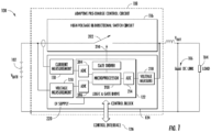
- FIG. 1 is a representative drawing of an adaptive pre-charge control circuit 108 for providing pre-charge capability in a solid state battery disconnect and protection system 100, according to exemplary embodiments.
- the solid state battery disconnect and protection system 100 consists of an electric vehicle (EV) battery 102, a load 104, and a DC link capacitor 106, with the adaptive pre-charge control circuit 108 disposed between the EV battery 102 and the load 104.
- the load 104 is an EV motor of an electric vehicle, but the load also includes other powered components within the electric vehicle, such as air conditioning compressors, window enabling motors, and so on.
- Each subunit in the vehicle has an input capacity, with the individual capacitors and number of subunits being unknown. The sum of individual capacitors is the DC link capacity (C DC ), symbolized by the DC link capacitor 106.
- C DC DC link capacity
- the adaptive pre-charge control circuit 108 is a solid state battery disconnect and protection circuit featuring a high-voltage bi-directional switch circuit 116, or high-voltage switch 116 for short, and a control block 124.
- Solid state battery disconnect and protection circuits use a microprocessor or microcontroller coupled with a current sensor to sample a waveform and detect any overcurrent scenarios. Solid state battery disconnect and protection circuits have very fast response time relative to traditional circuit breakers.
- the high-voltage switch 116 of the adaptive pre-charge control circuit 108 turns on (closes) or off (opens) to control (enable or prevent) current flow between the EV battery 102 and the load 104.
- control block 124 issues a PWM signal 210 to the high-voltage switch 116, causing a switch 202 therein to turn on and off at a ratio based on the duty cycle of the PWM signal.
- the on/off rate or number of switching events per time is defined by the PWM switching frequency.
- the duty cycle defines the ratio between on-time and the switching period.
- V batt of the EV battery 102 and a voltage, V out , of the DC link capacitor 106 are shown.
- the adaptive pre-charge control circuit 108 is designed to enable slow charging of the DC link capacitor 106 until its voltage is close to the voltage of the EV battery 102.
- V diff voltage difference between V out and V batt
- the high-voltage switch 116 will turn on (close), allowing current to flow freely between the EV battery 102 and the load 104. In this way, the EV battery 102 is able to safely power the load. Stated mathematically, once V batt - V out ⁇ V diff , then the switch will remain closed until the electric vehicle is turned off.
- the control block 124 features a microprocessor 208 and three analog-to-digital converters (ADCs) 204, 206, and 214.
- the control block 214 may be an equivalent integrated circuit.
- the ADC 204 measures the battery voltage, V batt
- the ADC 206 measures the output voltage, V out .
- the microprocessor 208 is presented with a measurement or a digital representation of the battery voltage, V batt , and the output voltage, V out .
- the ADC 204 measures and converts the voltages to digital values, while the ADC 206 measures current.
- the microprocessor 208 can then read these results and compute the voltage difference, V diff .
- the microprocessor 208 generates the PWM pattern to turn the switch 202 on and off.
- the control block 124 also features current measurement 118 and voltage measurement 128 at the input, V batt , as well as voltage measurement 218 at the output, V out .
- the logic and the gate drive of the adaptive pre-charge control circuit 108 cause issuance of the PWM signal 210 to the high-voltage switch 116.
- the PWM signal 210 will enable the high-voltage switch 202 to be turned on or off, thus enabling or preventing current flow between the EV battery 102 and the DC link capacitor 106.
- the adaptive pre-charge control circuit 108 thus implements pre-charge control with a PWM control signal, controlling the pulse width profile to control the current.
- the logic and gate drive 122 of the control block 124 is connected to a control interface 126, which may be a wired or a wireless connection.
- the PWM signal 210 of the adaptive pre-charge control circuit 108 supports more reliable pre-charge using a defined current pattern (e.g., one current pulse above, one current pulse below the overcurrent threshold) and/or measurement of the output voltage.
- a defined current pattern e.g., one current pulse above, one current pulse below the overcurrent threshold
- the sensor used by the current measurement 118 is a Hall-effect sensor that has a pre-defined threshold such that, when the current reaches the threshold, a logic signal will be issued to the logic and gate drive 122.
- the current measurement 118 may use shunt resistances to sense an overcurrent, in some embodiments. It will be appreciated, that virtually any current sensor type may be used in alternative embodiments.
- the adaptive pre-charge control circuit 108 also includes a current limiting function.
- the current sensor in FIG. 1 consists of the current measurement 118, with the circle denoting the wire being measured.
- the magnetic flux generated by the flowing current is converted to a voltage via the Hall effect.
- the voltage is compared to a reference in the sensor that represents the threshold voltage indicating an overcurrent.
- a single logic signal is generated and sent to the logic and gate drive 122. In exemplary embodiments, this happens within a microsecond timeframe.
- the current limiting function is triggered and the adaptive pre-charge control circuit 108 disconnects the battery and load (and stops charging). Without the current limiting function, the current would rise unbounded, stressing or damaging components and interconnects.
- the switch 202 of the high-voltage switch 116 is a solid state switching device, such as an insulated gate bipolar junction transistor (IGBT), a semiconductor such as a power metal-oxide semiconductor field-effect transistor (MOSFET), a thyristor, a silicon-controlled rectifier (SCR), a triode for alternating current (TRIAC), or any other suitable high-power controlled solid state device.
- the switch 202 connects or disconnects the EV battery 102 to the vehicle's high-voltage on-board systems.
- the switch 202 is bi-directional to allow the EV battery 102 to supply the vehicle (load 104) and to allow a charger to supply the battery.
- the switch 202 is controlled by a PWM signal 210 coming from the control block 124.
- Pre-charge circuits are commonly part of high-voltage systems, such as electronic vehicle systems, in which downstream capacitance can be exposed to inrush current when the vehicle is turned on. These pre-charge circuits typically have a large value resistor that is switched on before the vehicle is started and the DC link capacitor is slowly charged. Once the capacitor is sufficiently charged, the switch is closed entirely. Having a set pre-charge threshold does not account for battery discharge after vehicle use. Further, the prior art pre-charge circuits do not utilize pulse-width modulation to control the charging, as is done with the adaptive pre-charge control circuit 108.
- the adaptive pre-charge control circuit 108 thus provides a novel method to detect battery discharge and set a pre-charge threshold based on initial and final values of battery charge, while also more reliably detecting an overcurrent fault condition using one or more defined current pattern (e.g., one current pulse above, one current pulse below the overcurrent threshold) and/or measurement of the output voltage.
- one or more defined current pattern e.g., one current pulse above, one current pulse below the overcurrent threshold
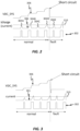
- FIG. 2 is a representative drawing of the operating principle of pulse width modulation used by the adaptive pre-charge control circuit 108, according to an exemplary embodiment.
- the PWM pattern can be defined to generate a specific current profile, such as one current pulse above, followed by one current pulse below the overcurrent threshold.
- the charging current 301 I charge
- FIG. 2 pulse intervals 302 are shown, with small amounts of current 304 being issued at each pulse.
- the DC link capacitor 106 is initially at zero volts, the charging current without control would be similar to a short circuit current and potentially lead to destruction.
- the current By issuing a short pulse, the current remains within safe limits and the DC link capacitor 106 is charged nominally. As the current is driven by the voltage difference, V diff , between the battery voltage, V batt , and the DC link voltage, V DC_SYS 306 (V out in FIG. 1 ), a growing DC link voltage, leads to a lower current for the next pulse. With each pulse, the DC link voltage 306 is increased. As shown, the charging current 301 can be defined so that only every second pulse exceeds limit 310.
- a first pulse 304A is below limit 310
- a second pulse 304B is above limit 310
- a third pulse 304C is below limit 310
- a fouth pulse 310D is above limit 310
- a fifth pulse 304E is also above limit 310. Because two consecutive pulses (304D, 304E) are above limit 310, a real overcurrent fault is detected.
- the overcurrent protection circuit is resettable. That is, when the circuit protection is tripped, the system may try again after a certain time to verify if the overcurrent condition remains, or if it was caused by a noise of some other transient effect.
- a similar method e.g., the use of a defined PWM pattern
- the DC-Link voltage is close to the battery voltage.
- FIG. 3 is a representative drawing of the operating principle of pulse width modulation used by the adaptive pre-charge control circuit 108, according to another exemplary embodiment.
- the PWM pattern is again defined to generate a specific current profile.
- the overcurrent threshold is disabled during pre-charge, and the voltage increment in V DC_SYS 306 is measured. If the voltage increment is not positive after applying a pulse, this indicates a real overcurrent fault for the current 301.
Landscapes
- Engineering & Computer Science (AREA)
- Power Engineering (AREA)
- Mechanical Engineering (AREA)
- Sustainable Development (AREA)
- Sustainable Energy (AREA)
- Transportation (AREA)
- Life Sciences & Earth Sciences (AREA)
- Physics & Mathematics (AREA)
- General Physics & Mathematics (AREA)
- Emergency Protection Circuit Devices (AREA)
- Charge And Discharge Circuits For Batteries Or The Like (AREA)
- Measurement Of Current Or Voltage (AREA)
- Protection Of Static Devices (AREA)
Abstract
Disclosed is an adaptive pre-charge control circuit, for use in a solid state battery disconnect and protection system, wherein the adaptive pre-charge control circuit includes a high-voltage switch coupled between an electric battery and a DC link capacitor of an electric vehicle, and wherein the electric vehicle is powered by the electric battery. The control circuit may be operable to issue a pulse width modulated (PWM) signal to generate a current profile wherein every other pulse exceeds a predefined limit, monitor, during pre-charging, the current profile, and to determine an overcurrent fault exists in the case that two consecutive pulses exceed the predefined limit.
Description
- Embodiments of the present disclosure relate to solid state battery disconnect and protection circuits, including a pre-charge control function.
- Pre-charge circuits are used in high voltage DC applications with capacitive loads that can result in high inrush currents during power up. Pre-charge of the powerline voltages is a preliminary mode which limits the inrush current. The pre-charge circuits thus prevent damage to system components by blocking high amperage current spikes.
- A high voltage system with a large capacitive load can be exposed to high electric current during initial turn-on. If not limited, the current can cause considerable stress or damage to the system components, including, but not limited to, causing contactors to weld closed.
- In electric vehicle applications, battery disconnects are implemented using contactors, overcurrent protection is implemented with a combination of the same contactors controlled by specific circuitry and additional protection elements such as fuses or pyrofuses, and pre-charge control is implemented with additional dedicated circuitry.
- In electric vehicle applications, the large capacitive load is the DC link in the electric motor. The "DC link capacitor" is actually the sum of several parallel capacitors in the subunits within the electric vehicle, one for the electric motor, another for the air conditioning compressor, another for the window enabling, and so on.
- Pre-charging of the DC link capacitor will occur with each vehicle start. The battery voltage may be different in each vehicle start, depending on the battery charge state. Thus, the battery voltage may be any value within the operating range of the battery, for example, 550V-800V in an 800V battery system. The pre-charging circuit limits the inrush current to slowly charge the downstream DC link capacitor. Once the voltage of the DC link capacitor is close to that of the battery, the main switches are permitted to close. Pre-charge circuits thus allow the current to flow in a controlled manner during vehicle startup.
- Pre-charge circuits in electric vehicles, built by an auxiliary switch in series with a large value resistance and placed in parallel with the main switch, control the inrush current going into the vehicle during startup. The main switch is open and the auxiliary switch closed, so that the DC link capacitor is slowly charged, as determined by the resistance. Once the DC link capacitor is sufficiently charged (so that its voltage is close to that of the battery), the main switch is closed all the way and the battery is able to safely supply power to the vehicle.
- However, pre-charge systems based on pulse-width modulation (PWM) control are usually operated above the nominal current for fast pre-charge function. In this use case, it is difficult to discriminate real overcurrent fault conditions.
- It is with respect to these and other considerations that the present improvements may be useful.
- This Summary is provided to introduce a selection of concepts in a simplified form that are further described below in the Detailed Description. This Summary is not intended to identify key or essential features of the claimed subject matter, nor is it intended as an aid in determining the scope of the claimed subject matter.
- In one approach, an adaptive pre-charge control circuit, for use in a solid state battery disconnect and protection system, may include a high-voltage switch coupled between an electric battery and a DC link capacitor of an electric vehicle, wherein the electric vehicle is powered by the electric battery, and a control circuit. The control circuit may be operable to issue a pulse width modulated (PWM) signal to generate a current profile wherein every other pulse exceeds a predefined limit. The control circuit may be further monitor, during pre-charging, the current profile, and determine an overcurrent fault exists in the case that two consecutive pulses exceed the predefined limit.
- In another approach, an adaptive pre-charge control circuit, for use in a solid state battery disconnect and protection system, may include a high-voltage switch coupled between an electric battery and a DC link capacitor of an electric vehicle, wherein the electric vehicle is powered by the electric battery, and a control circuit. The control circuit may be operable to issue a pulse width modulated (PWM) signal to generate a current profile, measure, during pre-charging, a voltage increment of a voltage, Vout of the DC link capacitor, and determine an overcurrent fault exists in the case that the voltage increment is not positive after applying a pulse.
- The accompanying drawings illustrate exemplary approaches of the disclosed embodiments so far devised for the practical application of the principles thereof, and in which:
-
FIG. 1 is a diagram illustrating an adaptive pre-charge control circuit for use in an electric vehicle system, in accordance with exemplary embodiments; -
FIG. 2 is a diagram illustrating the operating principle of pulse width modulation used by the adaptive pre-charge control circuit ofFIG. 1 , according to exemplary embodiments; and -
FIG. 3 is a diagram illustrating the operating principle of pulse width modulation used by the adaptive pre-charge control circuit ofFIG. 1 , according to exemplary embodiments. - The drawings are not necessarily to scale. The drawings are merely representations, not intended to portray specific parameters of the disclosure. The drawings are intended to depict exemplary embodiments of the disclosure, and therefore are not to be considered as limiting in scope. In the drawings, like numbering represents like elements.
- The present disclosure will now proceed with reference to the accompanying drawings, in which various approaches are shown. It will be appreciated, however, that the re-usable snap-in fitting may be embodied in many different forms and should not be construed as limited to the approaches set forth herein. Rather, these approaches are provided so that this disclosure will be thorough and complete, and will fully convey the scope of the disclosure to those skilled in the art.
- An adaptive pre-charge control circuit is disclosed for providing pre-charge capability in an electric vehicle. The adaptive pre-charge control circuit is disposed between an electric battery that supplies power to an electric vehicle and the load of the electric vehicle. By issuing a pulse-width modulated signal to a high-voltage switch, the voltage of a DC link capacitor representing the capacitors of the vehicle load can be changed. Once the voltage of the DC link capacitor is close to that of the electric battery, the high-voltage switch is turned on, enabling current to safely be delivered to the load. The adaptive pre-charge control circuit includes overvoltage protection and current limiting features. As will be further described herein, embodiments of the present disclosure can reliably detect overcurrent fault condition in fast PWM-based precharge functions using a defined current pattern (e.g., one current pulse above, one current pulse below the overcurrent threshold) and/or measurement of the output voltage.
-
FIG. 1 is a representative drawing of an adaptivepre-charge control circuit 108 for providing pre-charge capability in a solid state battery disconnect andprotection system 100, according to exemplary embodiments. The solid state battery disconnect andprotection system 100 consists of an electric vehicle (EV)battery 102, aload 104, and aDC link capacitor 106, with the adaptivepre-charge control circuit 108 disposed between theEV battery 102 and theload 104. Principally, theload 104 is an EV motor of an electric vehicle, but the load also includes other powered components within the electric vehicle, such as air conditioning compressors, window enabling motors, and so on. Each subunit in the vehicle has an input capacity, with the individual capacitors and number of subunits being unknown. The sum of individual capacitors is the DC link capacity (CDC), symbolized by theDC link capacitor 106. - The adaptive
pre-charge control circuit 108 is a solid state battery disconnect and protection circuit featuring a high-voltagebi-directional switch circuit 116, or high-voltage switch 116 for short, and acontrol block 124. Solid state battery disconnect and protection circuits use a microprocessor or microcontroller coupled with a current sensor to sample a waveform and detect any overcurrent scenarios. Solid state battery disconnect and protection circuits have very fast response time relative to traditional circuit breakers. The high-voltage switch 116 of the adaptivepre-charge control circuit 108 turns on (closes) or off (opens) to control (enable or prevent) current flow between theEV battery 102 and theload 104. In exemplary embodiments, thecontrol block 124 issues aPWM signal 210 to the high-voltage switch 116, causing aswitch 202 therein to turn on and off at a ratio based on the duty cycle of the PWM signal. The on/off rate or number of switching events per time is defined by the PWM switching frequency. The duty cycle defines the ratio between on-time and the switching period. - A voltage, Vbatt, of the
EV battery 102 and a voltage, Vout, of theDC link capacitor 106 are shown. In exemplary embodiments, the adaptivepre-charge control circuit 108 is designed to enable slow charging of theDC link capacitor 106 until its voltage is close to the voltage of theEV battery 102. Once a predefined difference, Vdiff, between Vout and Vbatt is reached, the high-voltage switch 116 will turn on (close), allowing current to flow freely between theEV battery 102 and theload 104. In this way, theEV battery 102 is able to safely power the load. Stated mathematically, once Vbatt - Vout ≤ Vdiff, then the switch will remain closed until the electric vehicle is turned off. - The
control block 124 features amicroprocessor 208 and three analog-to-digital converters (ADCs) 204, 206, and 214. In other embodiments, thecontrol block 214 may be an equivalent integrated circuit. TheADC 204 measures the battery voltage, Vbatt, while theADC 206 measures the output voltage, Vout. Before a computation can be made, themicroprocessor 208 is presented with a measurement or a digital representation of the battery voltage, Vbatt, and the output voltage, Vout. TheADC 204 measures and converts the voltages to digital values, while theADC 206 measures current. Themicroprocessor 208 can then read these results and compute the voltage difference, Vdiff. Further, themicroprocessor 208 generates the PWM pattern to turn theswitch 202 on and off. Thecontrol block 124 also featurescurrent measurement 118 andvoltage measurement 128 at the input, Vbatt, as well asvoltage measurement 218 at the output, Vout. In exemplary embodiments, the logic and the gate drive of the adaptivepre-charge control circuit 108 cause issuance of the PWM signal 210 to the high-voltage switch 116. ThePWM signal 210 will enable the high-voltage switch 202 to be turned on or off, thus enabling or preventing current flow between theEV battery 102 and theDC link capacitor 106. The adaptivepre-charge control circuit 108 thus implements pre-charge control with a PWM control signal, controlling the pulse width profile to control the current. The logic and gate drive 122 of thecontrol block 124 is connected to a control interface 126, which may be a wired or a wireless connection. - In exemplary embodiments, the PWM signal 210 of the adaptive
pre-charge control circuit 108 supports more reliable pre-charge using a defined current pattern (e.g., one current pulse above, one current pulse below the overcurrent threshold) and/or measurement of the output voltage. - In exemplary embodiments, the sensor used by the
current measurement 118 is a Hall-effect sensor that has a pre-defined threshold such that, when the current reaches the threshold, a logic signal will be issued to the logic andgate drive 122. As an alternative to using Hall sensors, thecurrent measurement 118 may use shunt resistances to sense an overcurrent, in some embodiments. It will be appreciated, that virtually any current sensor type may be used in alternative embodiments. In exemplary embodiments, the adaptivepre-charge control circuit 108 also includes a current limiting function. The current sensor inFIG. 1 consists of thecurrent measurement 118, with the circle denoting the wire being measured. The magnetic flux generated by the flowing current is converted to a voltage via the Hall effect. The voltage is compared to a reference in the sensor that represents the threshold voltage indicating an overcurrent. When an overcurrent occurs, a single logic signal is generated and sent to the logic andgate drive 122. In exemplary embodiments, this happens within a microsecond timeframe. - If the current exceeds a certain limit (e.g., twice consecutively), the current limiting function is triggered and the adaptive
pre-charge control circuit 108 disconnects the battery and load (and stops charging). Without the current limiting function, the current would rise unbounded, stressing or damaging components and interconnects. - In exemplary embodiments, the
switch 202 of the high-voltage switch 116 is a solid state switching device, such as an insulated gate bipolar junction transistor (IGBT), a semiconductor such as a power metal-oxide semiconductor field-effect transistor (MOSFET), a thyristor, a silicon-controlled rectifier (SCR), a triode for alternating current (TRIAC), or any other suitable high-power controlled solid state device. Theswitch 202 connects or disconnects theEV battery 102 to the vehicle's high-voltage on-board systems. In exemplary embodiments, theswitch 202 is bi-directional to allow theEV battery 102 to supply the vehicle (load 104) and to allow a charger to supply the battery. In exemplary embodiments, theswitch 202 is controlled by aPWM signal 210 coming from thecontrol block 124. - Pre-charge circuits are commonly part of high-voltage systems, such as electronic vehicle systems, in which downstream capacitance can be exposed to inrush current when the vehicle is turned on. These pre-charge circuits typically have a large value resistor that is switched on before the vehicle is started and the DC link capacitor is slowly charged. Once the capacitor is sufficiently charged, the switch is closed entirely. Having a set pre-charge threshold does not account for battery discharge after vehicle use. Further, the prior art pre-charge circuits do not utilize pulse-width modulation to control the charging, as is done with the adaptive
pre-charge control circuit 108. The adaptivepre-charge control circuit 108 thus provides a novel method to detect battery discharge and set a pre-charge threshold based on initial and final values of battery charge, while also more reliably detecting an overcurrent fault condition using one or more defined current pattern (e.g., one current pulse above, one current pulse below the overcurrent threshold) and/or measurement of the output voltage. -
FIG. 2 is a representative drawing of the operating principle of pulse width modulation used by the adaptivepre-charge control circuit 108, according to an exemplary embodiment. In this embodiment, the PWM pattern can be defined to generate a specific current profile, such as one current pulse above, followed by one current pulse below the overcurrent threshold. For the adaptivepre-charge control circuit 108, after turning on thebi-directional switch 202, the charging current 301 (Icharge), builds up. InFIG. 2 ,pulse intervals 302 are shown, with small amounts of current 304 being issued at each pulse. As theDC link capacitor 106 is initially at zero volts, the charging current without control would be similar to a short circuit current and potentially lead to destruction. By issuing a short pulse, the current remains within safe limits and theDC link capacitor 106 is charged nominally. As the current is driven by the voltage difference, Vdiff, between the battery voltage, Vbatt, and the DC link voltage, VDC_SYS 306 (Vout inFIG. 1 ), a growing DC link voltage, leads to a lower current for the next pulse. With each pulse, theDC link voltage 306 is increased. As shown, the charging current 301 can be defined so that only every second pulse exceedslimit 310. That is, afirst pulse 304A is belowlimit 310, asecond pulse 304B is abovelimit 310, athird pulse 304C is belowlimit 310, a fouth pulse 310D is abovelimit 310 and afifth pulse 304E is also abovelimit 310. Because two consecutive pulses (304D, 304E) are abovelimit 310, a real overcurrent fault is detected. - In some embodimetns, the overcurrent protection circuit is resettable. That is, when the circuit protection is tripped, the system may try again after a certain time to verify if the overcurrent condition remains, or if it was caused by a noise of some other transient effect. Upon reconnection, a similar method (e.g., the use of a defined PWM pattern) can be used to detect overcurrent events, even if the device is not in pre-charge mode (so the DC-Link voltage is close to the battery voltage).
-
FIG. 3 is a representative drawing of the operating principle of pulse width modulation used by the adaptivepre-charge control circuit 108, according to another exemplary embodiment. In this embodiment, the PWM pattern is again defined to generate a specific current profile. In this example, the overcurrent threshold is disabled during pre-charge, and the voltage increment inV DC_SYS 306 is measured. If the voltage increment is not positive after applying a pulse, this indicates a real overcurrent fault for the current 301. - The foregoing discussion has been presented for purposes of illustration and description and is not intended to limit the disclosure to the form or forms disclosed herein. For example, various features of the disclosure may be grouped together in one or more aspects, embodiments, or configurations for the purpose of streamlining the disclosure. However, it should be understood that various features of the certain aspects, embodiments, or configurations of the disclosure may be combined in alternate aspects, embodiments, or configurations. Moreover, the following claims are hereby incorporated into this Detailed Description by this reference, with each claim standing on its own as a separate embodiment of the present disclosure.
- As used herein, an element or step recited in the singular and proceeded with the word "a" or "an" should be understood as not excluding plural elements or steps, unless such exclusion is explicitly recited. Furthermore, references to "one embodiment" of the present disclosure are not intended to be interpreted as excluding the existence of additional embodiments that also incorporate the recited features.
- The use of "including," "comprising," or "having" and variations thereof herein is meant to encompass the items listed thereafter and equivalents thereof as well as additional items. Accordingly, the terms "including," "comprising," or "having" and variations thereof are open-ended expressions and can be used interchangeably herein.
- The present disclosure is not to be limited in scope by the specific embodiments described herein. Indeed, other various embodiments of and modifications to the present disclosure, in addition to those described herein, will be apparent to those of ordinary skill in the art from the foregoing description and accompanying drawings. Thus, such other embodiments and modifications are intended to fall within the scope of the present disclosure. Furthermore, the present disclosure has been described herein in the context of a particular implementation in a particular environment for a particular purpose. Those of ordinary skill in the art will recognize the usefulness is not limited thereto and the present disclosure may be beneficially implemented in any number of environments for any number of purposes. Thus, the claims set forth below are to be construed in view of the full breadth of the present disclosure as described herein.
Claims (6)
- An adaptive pre-charge control circuit, for use in a solid state battery disconnect and protection system, the adaptive pre-charge control circuit comprising:a high-voltage switch coupled between an electric battery and a DC link capacitor of an electric vehicle, wherein the electric vehicle is powered by the electric battery; anda control circuit operable to:issue a pulse width modulated (PWM) signal to generate a current profile wherein every other pulse exceeds a predefined limit;monitor, during pre-charging, the current profile; anddetermine an overcurrent fault exists in the case that two consecutive pulses exceed the predefined limit.
- The adaptive pre-charge control circuit of claim 1, wherein the control circuit is further operable to open the high-voltage switch when the overcurrent fault is determined.
- The adaptive pre-charge control circuit of claim 1, further comprising resetting the control circuit following the overcurrent fault.
- An adaptive pre-charge control circuit, for use in a solid state battery disconnect and protection system, the adaptive pre-charge control circuit comprising:a high-voltage switch coupled between an electric battery and a DC link capacitor of an electric vehicle, wherein the electric vehicle is powered by the electric battery; anda control circuit operable to:issue a pulse width modulated (PWM) signal to generate a current profile;measure, during pre-charging, a voltage increment of a voltage, Vout of the DC link capacitor; anddetermine an overcurrent fault exists in the case that the voltage increment is not positive after applying a pulse.
- The adaptive pre-charge control circuit of claim 4, wherein the control circuit is further operable to open the high-voltage switch when the overcurrent fault is determined.
- The adaptive pre-charge control circuit of claim 4, further comprising resetting the control circuit following the overcurrent fault.
Applications Claiming Priority (1)
| Application Number | Priority Date | Filing Date | Title |
|---|---|---|---|
| US202363461789P | 2023-04-25 | 2023-04-25 |
Publications (1)
| Publication Number | Publication Date |
|---|---|
| EP4461581A1 true EP4461581A1 (en) | 2024-11-13 |
Family
ID=90810161
Family Applications (1)
| Application Number | Title | Priority Date | Filing Date |
|---|---|---|---|
| EP24171374.2A Pending EP4461581A1 (en) | 2023-04-25 | 2024-04-19 | Pre-charge short circuit detection |
Country Status (6)
| Country | Link |
|---|---|
| US (1) | US12592557B2 (en) |
| EP (1) | EP4461581A1 (en) |
| JP (1) | JP7806380B2 (en) |
| KR (1) | KR20240157562A (en) |
| CN (1) | CN118842120A (en) |
| TW (1) | TWI906831B (en) |
Citations (4)
| Publication number | Priority date | Publication date | Assignee | Title |
|---|---|---|---|---|
| US7868483B2 (en) * | 2007-09-06 | 2011-01-11 | O2Micro, Inc. | Power management systems with current sensors |
| JP2012044844A (en) * | 2010-08-23 | 2012-03-01 | Mitsumi Electric Co Ltd | Protection circuit |
| US10090689B2 (en) * | 2013-12-13 | 2018-10-02 | Hytera Communications Corp., Ltd. | Overcurrent protection circuit and method for limiting discharge current of battery within safety limiting value |
| EP3421287A1 (en) * | 2017-06-28 | 2019-01-02 | Fico Triad, S.A. | Battery connection system for electric and/or hybrid vehicles |
Family Cites Families (33)
| Publication number | Priority date | Publication date | Assignee | Title |
|---|---|---|---|---|
| US5181155A (en) * | 1990-08-30 | 1993-01-19 | Beg Mirza A | Overcurrent trip circuit |
| JP4059821B2 (en) | 2003-08-19 | 2008-03-12 | オリンパス株式会社 | Power supply device and camera power supply device |
| JP2008022597A (en) | 2006-07-11 | 2008-01-31 | Meidensha Corp | Dc power supply for electronic apparatus |
| US7872447B2 (en) * | 2006-12-25 | 2011-01-18 | Panasonic Corporation | Electrical storage apparatus for use in auxiliary power supply supplying electric power from electric storage device upon voltage drop of main power supply |
| WO2010144077A1 (en) * | 2009-06-08 | 2010-12-16 | Hewlett-Packard Development Company, L.P. | Decreasing voltage detection with control signaling |
| US8218274B2 (en) * | 2009-12-15 | 2012-07-10 | Eaton Corporation | Direct current arc fault circuit interrupter, direct current arc fault detector, noise blanking circuit for a direct current arc fault circuit interrupter, and method of detecting arc faults |
| JP5627264B2 (en) | 2010-03-27 | 2014-11-19 | 三洋電機株式会社 | Power supply device for vehicle and vehicle equipped with this power supply device |
| US8716997B2 (en) * | 2010-06-16 | 2014-05-06 | Honeywell International, Inc. | High power DC SSPC with capability of soft turn-on large capacitive loads |
| JP5669465B2 (en) | 2010-07-08 | 2015-02-12 | キヤノン株式会社 | Power circuit |
| JP5707812B2 (en) | 2010-09-24 | 2015-04-30 | カシオ計算機株式会社 | Current detection circuit |
| US20120139514A1 (en) * | 2010-12-07 | 2012-06-07 | Eaton Corporation | Switch-mode power supply with enhanced current source capability |
| US8779735B2 (en) * | 2011-03-15 | 2014-07-15 | Infineon Technologies Ag | System and method for an overcurrent protection and interface circuit between an energy source and a load |
| US8553373B2 (en) * | 2011-08-25 | 2013-10-08 | Hamilton Sundstrand Corporation | Solid state power controller for high voltage direct current systems |
| KR20140055986A (en) * | 2012-10-31 | 2014-05-09 | 대성전기공업 주식회사 | Apparatus for switch relay |
| JP6062327B2 (en) * | 2013-07-09 | 2017-01-18 | 日立オートモティブシステムズ株式会社 | Inverter device and electric vehicle |
| US9925878B2 (en) * | 2013-09-26 | 2018-03-27 | Ford Global Technologies, Llc | Bus pre-charge control using a buck converter |
| US9573474B2 (en) * | 2014-03-06 | 2017-02-21 | Ford Global Technologies, Llc | Capacitor precharging and capacitance/resistance measurement in electric vehicle drive system |
| JP6503636B2 (en) | 2014-05-12 | 2019-04-24 | 株式会社ジェイテクト | Motor controller |
| JP6296169B2 (en) * | 2014-11-14 | 2018-03-20 | アイシン・エィ・ダブリュ株式会社 | Inverter control device and vehicle control device |
| WO2016104318A1 (en) * | 2014-12-25 | 2016-06-30 | アイシン・エィ・ダブリュ株式会社 | Rotating electric machine control device |
| JP2016127347A (en) | 2014-12-26 | 2016-07-11 | 富士ゼロックス株式会社 | Switch device |
| JP6638616B2 (en) * | 2016-09-30 | 2020-01-29 | 株式会社デンソー | Power control device |
| DE102018207247B4 (en) * | 2017-12-15 | 2024-07-11 | Bayerische Motoren Werke Aktiengesellschaft | Disconnecting device for a high-voltage electrical system of a motor vehicle, high-voltage electrical system and motor vehicle |
| US10256024B1 (en) * | 2018-01-15 | 2019-04-09 | Ford Global Technologies, Llc | Power converter temperature estimation |
| US11518262B2 (en) * | 2018-08-03 | 2022-12-06 | University Of Ontario Institute Of Technology | Wide-output voltage range on-board battery charger for electric vehicles |
| US11689010B2 (en) * | 2019-02-22 | 2023-06-27 | Eaton Intelligent Power Limited | Coolant fitting promoting turbulent flow |
| CN113615031B (en) | 2019-03-26 | 2024-10-15 | Tvs电机股份有限公司 | Vehicle pre-charging system |
| WO2021009217A2 (en) * | 2019-07-15 | 2021-01-21 | Eaton Intelligent Power Limited | Power distribution and circuit protection for a mobile application having a high efficiency inverter |
| CN113002303B (en) | 2019-12-19 | 2023-03-28 | 联合汽车电子有限公司 | Pre-charging circuit and pre-charging method, bidirectional direct current converter and electric automobile |
| JP7620090B2 (en) * | 2021-05-11 | 2025-01-22 | ファナック株式会社 | Capacitor deterioration detection device and converter system |
| US12012006B2 (en) * | 2022-03-11 | 2024-06-18 | GM Global Technology Operations LLC | Circuit-triggered fault mitigation for battery electric system and motor vehicle having the same |
| US12370916B2 (en) * | 2022-10-24 | 2025-07-29 | Littelfuse, Inc. | Adaptive pre-charge control for electric vehicle DC link capacitor |
| US20240339990A1 (en) * | 2023-04-06 | 2024-10-10 | GM Global Technology Operations LLC | Smart electronically resettable fuse with load pre-charging |
-
2024
- 2024-04-19 EP EP24171374.2A patent/EP4461581A1/en active Pending
- 2024-04-19 JP JP2024068352A patent/JP7806380B2/en active Active
- 2024-04-22 TW TW113114893A patent/TWI906831B/en active
- 2024-04-23 KR KR1020240053801A patent/KR20240157562A/en active Pending
- 2024-04-24 US US18/644,289 patent/US12592557B2/en active Active
- 2024-04-25 CN CN202410504950.1A patent/CN118842120A/en active Pending
Patent Citations (4)
| Publication number | Priority date | Publication date | Assignee | Title |
|---|---|---|---|---|
| US7868483B2 (en) * | 2007-09-06 | 2011-01-11 | O2Micro, Inc. | Power management systems with current sensors |
| JP2012044844A (en) * | 2010-08-23 | 2012-03-01 | Mitsumi Electric Co Ltd | Protection circuit |
| US10090689B2 (en) * | 2013-12-13 | 2018-10-02 | Hytera Communications Corp., Ltd. | Overcurrent protection circuit and method for limiting discharge current of battery within safety limiting value |
| EP3421287A1 (en) * | 2017-06-28 | 2019-01-02 | Fico Triad, S.A. | Battery connection system for electric and/or hybrid vehicles |
Also Published As
| Publication number | Publication date |
|---|---|
| US12592557B2 (en) | 2026-03-31 |
| JP2024157535A (en) | 2024-11-07 |
| CN118842120A (en) | 2024-10-25 |
| US20240364099A1 (en) | 2024-10-31 |
| TW202445945A (en) | 2024-11-16 |
| TWI906831B (en) | 2025-12-01 |
| JP7806380B2 (en) | 2026-01-27 |
| KR20240157562A (en) | 2024-11-01 |
Similar Documents
| Publication | Publication Date | Title |
|---|---|---|
| US12370916B2 (en) | Adaptive pre-charge control for electric vehicle DC link capacitor | |
| CN101868899B (en) | Overcurrent protection in a dimmer circuit | |
| CN111181426B (en) | Boost converter circuit and method of controlling transistor switches in the circuit | |
| CN106416072B (en) | Apparatus and method for generating dynamic reference signal for driving circuit of semiconductor power switch | |
| CN110291715B (en) | motor driver | |
| US11372047B2 (en) | Method for detecting an insulation fault in a motor arrangement, method for detecting a motor phase interruption in a motor arrangement, and drive circuit for driving an electronically commutated motor | |
| US11011974B2 (en) | Inverter arrangement, electric drive system, and method for discharging a DC link capacitor in an inverter arrangement | |
| KR101463044B1 (en) | Self power circuit for protecting relay | |
| CN105896940A (en) | Power conversion apparatus | |
| US9941815B2 (en) | Power conversion apparatus with overcurrent simulating circuit | |
| JP2010220470A (en) | Failure detector of power element | |
| EP3182572A1 (en) | Electronic circuit and method for operating an electronic circuit | |
| KR20160146538A (en) | Inverter control circuit | |
| JPH1198835A (en) | H-bridge step-up circuit | |
| US12592557B2 (en) | Pre-charge short circuit detection | |
| US20240364100A1 (en) | Overcurrent protection based on slope detection | |
| KR102965443B1 (en) | Adaptive pre-charge control for electric vehicle dc link capacitor | |
| CN108141146A (en) | Electric power converter | |
| CN114175433A (en) | Overcurrent protection device for a DC power supply system | |
| CN113676116B (en) | Active discharge circuit with fault diagnosis | |
| CN113228499B (en) | A method and control system for controlling a multi-phase rotating electric machine | |
| CN112352373B (en) | Device for protecting power components of a transistor bridge | |
| CN110235330A (en) | Discharge circuits for high voltage electrical systems | |
| KR20120139214A (en) | A motor driver device by sensing input power(voltage/current) |
Legal Events
| Date | Code | Title | Description |
|---|---|---|---|
| PUAI | Public reference made under article 153(3) epc to a published international application that has entered the european phase |
Free format text: ORIGINAL CODE: 0009012 |
|
| STAA | Information on the status of an ep patent application or granted ep patent |
Free format text: STATUS: THE APPLICATION HAS BEEN PUBLISHED |
|
| AK | Designated contracting states |
Kind code of ref document: A1 Designated state(s): AL AT BE BG CH CY CZ DE DK EE ES FI FR GB GR HR HU IE IS IT LI LT LU LV MC ME MK MT NL NO PL PT RO RS SE SI SK SM TR |
|
| STAA | Information on the status of an ep patent application or granted ep patent |
Free format text: STATUS: REQUEST FOR EXAMINATION WAS MADE |
|
| 17P | Request for examination filed |
Effective date: 20250510 |