EP4461461A1 - Machine tool and method for working wooden workpieces - Google Patents
Machine tool and method for working wooden workpieces Download PDFInfo
- Publication number
- EP4461461A1 EP4461461A1 EP24175167.6A EP24175167A EP4461461A1 EP 4461461 A1 EP4461461 A1 EP 4461461A1 EP 24175167 A EP24175167 A EP 24175167A EP 4461461 A1 EP4461461 A1 EP 4461461A1
- Authority
- EP
- European Patent Office
- Prior art keywords
- marking device
- main body
- working
- marking
- tool
- Prior art date
- Legal status (The legal status is an assumption and is not a legal conclusion. Google has not performed a legal analysis and makes no representation as to the accuracy of the status listed.)
- Granted
Links
Images

Classifications
-
- B—PERFORMING OPERATIONS; TRANSPORTING
- B27—WORKING OR PRESERVING WOOD OR SIMILAR MATERIAL; NAILING OR STAPLING MACHINES IN GENERAL
- B27C—PLANING, DRILLING, MILLING, TURNING OR UNIVERSAL MACHINES FOR WOOD OR SIMILAR MATERIAL
- B27C9/00—Multi-purpose machines; Universal machines; Equipment therefor
- B27C9/02—Multi-purpose machines; Universal machines; Equipment therefor with a single working spindle
-
- B—PERFORMING OPERATIONS; TRANSPORTING
- B23—MACHINE TOOLS; METAL-WORKING NOT OTHERWISE PROVIDED FOR
- B23Q—DETAILS, COMPONENTS, OR ACCESSORIES FOR MACHINE TOOLS, e.g. ARRANGEMENTS FOR COPYING OR CONTROLLING; MACHINE TOOLS IN GENERAL CHARACTERISED BY THE CONSTRUCTION OF PARTICULAR DETAILS OR COMPONENTS; COMBINATIONS OR ASSOCIATIONS OF METAL-WORKING MACHINES, NOT DIRECTED TO A PARTICULAR RESULT
- B23Q39/00—Metal-working machines incorporating a plurality of sub-assemblies, each capable of performing a metal-working operation
- B23Q39/02—Metal-working machines incorporating a plurality of sub-assemblies, each capable of performing a metal-working operation the sub-assemblies being capable of being brought to act at a single operating station
- B23Q39/021—Metal-working machines incorporating a plurality of sub-assemblies, each capable of performing a metal-working operation the sub-assemblies being capable of being brought to act at a single operating station with a plurality of toolheads per workholder, whereby the toolhead is a main spindle, a multispindle, a revolver or the like
- B23Q39/025—Metal-working machines incorporating a plurality of sub-assemblies, each capable of performing a metal-working operation the sub-assemblies being capable of being brought to act at a single operating station with a plurality of toolheads per workholder, whereby the toolhead is a main spindle, a multispindle, a revolver or the like with different working directions of toolheads on same workholder
- B23Q39/027—Metal-working machines incorporating a plurality of sub-assemblies, each capable of performing a metal-working operation the sub-assemblies being capable of being brought to act at a single operating station with a plurality of toolheads per workholder, whereby the toolhead is a main spindle, a multispindle, a revolver or the like with different working directions of toolheads on same workholder consecutive working of toolheads
-
- B—PERFORMING OPERATIONS; TRANSPORTING
- B27—WORKING OR PRESERVING WOOD OR SIMILAR MATERIAL; NAILING OR STAPLING MACHINES IN GENERAL
- B27M—WORKING OF WOOD NOT PROVIDED FOR IN SUBCLASSES B27B - B27L; MANUFACTURE OF SPECIFIC WOODEN ARTICLES
- B27M1/00—Working of wood not provided for in subclasses B27B - B27L, e.g. by stretching
- B27M1/08—Working of wood not provided for in subclasses B27B - B27L, e.g. by stretching by multi-step processes
-
- B—PERFORMING OPERATIONS; TRANSPORTING
- B23—MACHINE TOOLS; METAL-WORKING NOT OTHERWISE PROVIDED FOR
- B23Q—DETAILS, COMPONENTS, OR ACCESSORIES FOR MACHINE TOOLS, e.g. ARRANGEMENTS FOR COPYING OR CONTROLLING; MACHINE TOOLS IN GENERAL CHARACTERISED BY THE CONSTRUCTION OF PARTICULAR DETAILS OR COMPONENTS; COMBINATIONS OR ASSOCIATIONS OF METAL-WORKING MACHINES, NOT DIRECTED TO A PARTICULAR RESULT
- B23Q2220/00—Machine tool components
- B23Q2220/006—Spindle heads
Definitions
- This invention relates to a machine tool and a method for machining wooden semiproducts.
- This invention also relates to a working head for machine tools configured to perform cutting operations on wooden semiproducts.
- the invention falls within the manufacturing sector and is applied in particular in the sector of machining wood.
- the need is felt of being able to perform different types of machining operations on a same semiproduct without having to move the semiproduct between various machines or between different units of the same machine.
- marking means the operation of marking the semiproduct so as to be able to indicate the parts to be cut, to indicate the direction of the cuts or to label the semiproducts with information on the specifications of the customer or on the destination of the semiproduct by forming alphanumeric characters on the surface of the semiproduct. Also, the marking is used to mark the position of holes or parts to be assembled, thus helping the operators to position the parts correctly during the final assembly.
- Multifunction machines which combine mechanical machining tools and markers. Structurally, these machines comprise a work table defining a supporting surface for the semiproducts and a working head which may be adjustable in height relative to the work table.
- the working head is provided with a working tool, such as, for example, a cutting tool, and a marking device.
- the tool protrudes from the main body of the working head.
- the choice of the working tool depends on the specific production needs and on the type of material that must be machined.
- the marking device protrudes from the main body of the working head and comprises one of the following devices: thin-pointed marking device, paint marking device, electronic ink marking device or laser marking device.
- thin-pointed marking device paint marking device
- electronic ink marking device electronic ink marking device
- laser marking device The choice of the marking device depends on the specific needs of the production and on the type of wood that has to be marked.
- the machines typically also comprise a control unit, used for programming the machine and controlling the machining process, and a movement system which controls at least the movement of the working head relative to the work table.
- the working tool and the marking device extend in a fixed and permanent manner from the main body of the working head and the latter, for this reason, is particularly bulky. It follows that the entire machine tool, and in particular the relative operating zone, must be oversized to allow an optimum movement of the working head.
- the marking device is constantly exposed to the working environment: it follows that dust, detritus and generic residue of the material machined repeatedly enter into contact with the marking device, soiling it.
- One or more of the following problems may therefore occur. Premature wear of the marking device: dust and waste materials may cause a greater wear of the marking device, leading to a shorter life than that foreseen by the manufacturer.
- the marking accuracy could be compromised.
- the dust may, for example, interfere with the capacity of the marking device to correctly adhere to the surface of the semiproduct, causing poorly defined or out of position markings.
- Difficulty cleaning if the marking device has been exposed to large amounts of dust and debris, it may be more difficult to remove the dirt and return it to the clean state. This may require the use of expensive and lengthy special maintenance operations and additional cleaning tools.
- the technical purpose of this invention is therefore to provide a machine tool and a method for machining wooden semiproducts as well as a working head for said type of machine tool configured to perform cutting operations on wooden semiproducts which are free of the above-mentioned drawbacks of the prior art.
- the aim of this invention is therefore to provide a machine tool and a method for machining wooden semiproducts as well as a working head for this type of machine tool configured to perform cutting operations on wooden semiproducts which allow the overall dimensions to be reduced.
- a further aim of this invention is to provide a machine tool and a method for machining wooden semiproducts as well as a working head for this type of machine tool configured to perform cutting operations on wooden semiproducts which allow the structural integrity at least of the marking device to be protected and/or to increase the service life.
- a further aim of this invention is to provide a machine tool and a method for machining wooden semiproducts as well as a working head for this type of machine tool configured to perform cutting operations on wooden semiproducts which, at the same time, do not excessively complicate the structure of the device and/or increase the production costs.
- the machine tool comprises a work table defining a supporting surface for one or more semiproducts to be machined.
- the work table may be of the fixed or mobile type.
- the machine comprises at least one working head configured to operate on the one or more semiproducts.
- the machine comprises a movement system configured to move the at least one working head relative to the respective work table.
- the movement system is also configured for moving the one or more semiproducts on the work table.
- the machine comprises a control unit connected to the work table, to the working head and to the movement system.
- the control unit is configured for controlling the machine tool in such a way as to manage the operations.
- the working head comprises a main body.
- the main body is box-shaped.
- the main body has an elongate shape along a main axis of extension.
- the main body has a predominant dimension of extension.
- the main body is provided with a working tool, which is projecting from the main body.
- the working tool may be of any type, in accordance with the general nature of the solution.
- the choice of the working tool depends on the specific production needs and on the type of material that must be machined.
- the working tool is of the motor-driven type.
- the working tool comprises a cutting tool, such as, for example, a circular saw, a milling cutter, a drill or a blade for wood.
- the main body includes a marking device.
- the marking device may be a contact marking device (for marking by means of an incision, for example) or a spray marking device.
- the marking device may be of the ink type or of the paint type.
- the marking device may also be of the electronic ink type or a laser marking device according to the generality of the solution. As with the working tool, the choice of the marking device depends on the specific needs of the production and the type of material that has to be marked. The choice of the type of marking device is independent of the choice of the type of working tool.
- the marking device is configured to be switchable between an extracted configuration, wherein the marking device projects from the main body, and a retracted configuration, wherein the marking device is accommodated inside the main body.
- the extracted configuration is particularly suitable for the marking operations.
- the retracted configuration is suitable for disengaging the marking device, that is to say, to a relative non-operating configuration.
- This technical feature makes it possible to reduce the dimensions of the working head at least in the retracted configuration of the marking device.
- this technical feature allows the marking device to be protected from the surrounding work environment at least in the relative disengaged configuration and therefore allows the marking device to be protected from the dust and detritus which would otherwise be deposited on the marking device.
- the marking device in the retracted configuration, is inserted in its entirety in the main body. In other words, in the retracted configuration, the marking device does not have portions projecting outside the main body.
- the marking device is only partly inserted inside the main body.
- the working head also comprises a drive mechanism configured to allow a movement of the marking device between the extracted configuration and the retracted configuration and vice versa.
- the main body has a containing space dedicated to housing at least the marking device and the drive mechanism.
- the containing space may be made in a peripheral portion of the main body.
- the containing space is made on an external wall of the main body.
- this feature allows the marking device to be easily reached by an operator and to facilitate any maintenance or replacement operations.
- the main body comprises a supporting plate connected to the above-mentioned movement system.
- the supporting plate defines the above-mentioned external wall in which the containing space is made for housing at least the marking device and the drive mechanism.
- the main body also comprises a motor stably fixed to the supporting plate and connected to the working tool for actuating the working tool.
- the motor is of the electric type.
- the working tool is connected to and projected from the motor whilst the marking device is accommodated in the supporting plate.
- the working tool and the marking device are mounted on separate portions of the main body.
- the working tool and the marking device are mounted on opposite ends of the main body.
- the working tool and the marking device are mounted in such a way as to be oriented on opposite directions of the working head.
- the supporting plate is rotatably connected to the movement system of the machine.
- the working head can be moved in rotation so as to selectively set up the working tool or the marking device for operating on the semiproduct.
- the working head can be rotated by the movement system by 180°.
- the working head may comprise a cover dedicated to the covering of the containing space.
- the drive mechanism is configured for making a sliding coupling between the main body and the marking device.
- the marking device can be moved along a rectilinear trajectory between the extracted configuration and the retracted configuration and vice versa. If the main body has an elongate shape, the rectilinear trajectory is parallel to the above-mentioned main axis of extension.
- the drive mechanism is configured for forming a pin between the main body and the marking device.
- the marking device is therefore pivoting along a circular trajectory between the extracted configuration and the retracted configuration and vice versa.
- the marking device is moved in rotation about the above-mentioned pin from the extracted configuration to the retracted configuration and vice versa.
- the marking device in the retracted configuration, is substantially adherent to a wall of the containing space.
- the device describes an arc of 180° between the extracted configuration and the retracted configuration and vice versa.
- the drive mechanism comprises at least one operating arm provided with a first end pivoted to the main body and a second end, opposite the first end, pivoted to the marking device.
- the marking device can be moved along a trajectory of roto-translation relative to the main body between the extracted configuration and the retracted configuration and vice versa.
- the working head may comprise an actuator connected to the drive mechanism and to the control unit.
- the actuator is configured at least for moving the marking device between the extracted configuration and the retracted configuration and vice versa.
- the actuator is of the pneumatic type.
- the actuator may be of the hydraulic or electric type. If present, the actuator is also accommodated in the above-mentioned containing space. Despite the presence of the actuator, the marker may be switched manually by an operator between the two configurations.
- the actuator is not provided and the marking device can only be switched manually by an operator between the two configurations.
- This invention also relates to a working head for the above-mentioned type of machine tool, which is configured to perform cutting operations on wooden semiproducts.
- This invention also relates to a method for machining wooden semiproducts.
- the method is implemented using the above-mentioned machine tool for machining wooden semiproducts.
- the method comprises a step of feeding one or more semiproducts on the work table.
- the method comprises a step of machining the semiproduct using the working tool mounted on the main body of the working head.
- the working tool is a cutting tool and at least one cutting operation is performed on the semiproduct in the machining step.
- the method comprises a step of marking the semiproduct by means of the marking device mounted on the main body of the working head.
- the marking device in the step of marking the semiproduct, is switched between the retracted configuration, wherein the marking device is accommodated inside the main body, and the extracted configuration, wherein the marking device is projecting from the main body and vice versa.
- the marking device before marking the semiproduct, the marking device is switched from the retracted configuration to the extended configuration. Once the marking of the semiproduct has been completed, the marking device is switched from the extracted configuration to the retracted configuration.
- the marking device can be moved along a rectilinear trajectory between the extracted configuration and the retracted configuration and vice versa.
- the marking device can be moved along a circular trajectory between the extracted configuration and the retracted configuration and vice versa. In other words, according to this embodiment, the marking device pivots between the two configurations. According to a further embodiment of the method, during the step of moving the semiproduct, the marking device can be moved along a trajectory of roto-translation between the extracted configuration and the retracted configuration and vice versa.
- the marking device in the retracted configuration is at a first distance from the working tool whilst in the extracted configuration the marking device is at a second distance from the working tool.
- the second distance may be greater than the first distance.
- the marking device can be moved between the extracted configuration and the retracted configuration and vice versa by means of an actuator.
- the method comprises a step of rotating the working head by means of the movement system of the machine tool so as to selectively set up the working tool or the marking device to operate on the semiproduct.
- the step of rotating the working head is interposed between the step of machining the semiproduct and the step of marking the semiproduct.
- the working head is rotated by 180° to selectively set up the working tool and the marking device.
- the numeral "100” denotes in its entirety a machine tool (illustrated schematically and only partly in the accompanying drawings).
- the machine tool 100 is classified in the manufacturing sector and is used in particular in the machining of wooden semiproducts.
- the machine tool 100 is used in the machining of wood.
- the machine tool 100 comprises a work table (not illustrated) defining a supporting surface on which one or more semiproducts to be machined are positioned.
- the work table may be of the fixed or mobile type.
- the machine tool 100 comprises an above-mentioned working head 1 which is adjustable at least towards and away from the work table.
- the machine tool 100 comprises a system 110 for moving the working head 1 configured to allow and actuate the movement of the working head 1 at least relative to the work table.
- the movement system 110 may also be configured for moving the one or more semiproducts on the work table.
- the machine tool 100 also comprises a control unit "U" connected to the work table, to the working head 1 and to the movement system 110.
- the control unit is configured for controlling the machine tool 100.
- the control unit "U” is configured for controlling the machining and in particular for controlling and moving and actuating the working head 1.
- the machine tool 100 may also comprise a safety system for protecting the operator during the machining.
- the system may include protection screens, emergency switches, safety sensors and/or other components.
- the working head 1 comprises a main box-shaped body 10.
- the main body has a first portion 11 and a second portion 12, different from the first portion 11.
- the main body 10 has an elongate shape along a main axis of extension "X": the first portion 11 and the second portion 12 of the main body 10 are made on opposite ends of the main body 10.
- the main body 10 is provided with a working tool 20 mounted on the first portion 11 so as to be projecting from the first portion 11.
- the working tool 20 is preferably a cutting tool (for example a blade positioned in a plane at right angles to the main axis of extension X).
- the working tool 20 is of the motor-driven type.
- the working tool 20 is configured for performing operations different from the cutting operations.
- the working head 1 comprises a marking device 30, mounted in the second portion 12 of the main body 10.
- the marking device 30 According to the preferred embodiment, therefore, the working tool 20 is mounted on the first end of the main body 10 (corresponding to the first portion 11 of the main body 10).
- the marking device 30 is mounted on the second end of the main body 10, opposite the first end (corresponding to the second portion 12 of the main body 10).
- the marking device 30 may be either a contact marking device or a spray marking device.
- the marking device 30 may be of the ink type or of the paint type.
- the marking device 30 may also be of the electronic ink type or a laser marking device according to the generality of the solution.
- the choice of the marking device 30 depends on the specific needs of the production and on the type of material that has to be marked. The choice of the type of marking device 30 is not, however, correlated with the choice of the type of working tool 20.
- the marking device 30 is a contact marking device and comprises a marking head 31.
- the marking device 30 is configured to be switchable between an extracted configuration, wherein the marking device 30 projects from the main body (and in particular from the second portion 12 of the main body 10), and a retracted configuration, wherein the marking device 30 is accommodated inside the main body 10 (and in particular inside the second portion 12 of the main body 10).
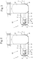
- the extracted configuration is suitable for the marking operations of the marking device 30 and is illustrated by way of example in Figure 2 .
- the retracted configuration is a disengaged configuration of the marking device 30 and is illustrated by way of example in Figure 3 .
- the marking device 30 is inserted in its entirety in the main body 10. In other words, in the retracted configuration, the marking device 30 does not have portions projecting outside the main body 10.
- the working head 1 comprises a drive mechanism 40 configured to allow a movement of the marking device 30 between the extracted configuration and the retracted configuration and vice versa.
- the movement mechanism 40 comprises an actuator 50 configured for moving the marking device 30 between the extracted configuration and the retracted configuration and vice versa.
- the actuator 50 is connected to the control unit "U" and can be operated by the latter.
- the actuator 50 is of the pneumatic type.
- the switching of the marking device 30 between the two configurations may in any case be performed manually by an operator.
- the main body 10 has a containing space 13 dedicated to housing at least the marking device 30 and the drive mechanism 40.
- the containing space is configured for also housing the actuator 50.
- the containing space 13 is substantially shaped to match the structure of the marking device 30 and/or shaped to match a movement path of the marking device 30 between the two configurations.
- the containing space 13 is made in a peripheral portion of the main body 10.
- the containing space 13 is made on an external wall 14 of the main body 10.
- the main body 10 comprises a supporting plate 16 connected to the above-mentioned movement system 110.
- the supporting plate 16 defines the above-mentioned external wall 14 in which the containing space 13 is made for housing at least the marking device 30 and the drive mechanism 40.
- the main body 10 also comprises a motor 15 stably fixed to the supporting plate 16 and connected to the working tool 20 for actuating the working tool 20.
- the motor 15 for actuating the working tool 20 is connected to the control unit "U" and to the working tool 20 and configured for operating the working tool 20.
- the motor 15 is an electric motor.
- the working tool 20 is connected to and projects from the motor 15 whilst the marking device 30 is accommodated in the supporting plate 16.
- the supporting plate 16 is rotatably connected to the movement system 110 of the machine tool 100.
- the working head 1 can be moved in rotation so as to selectively set up the working tool 20 or the marking device 30 to operate on the semiproduct.
- the drive mechanism 40 is configured for forming a sliding coupling between the main body 10 and the marking device 30: the marking device 30 can therefore be moved along a rectilinear trajectory between the extracted configuration and the retracted configuration and vice versa.
- the drive mechanism 40 comprises an actuator 50 of the pneumatic or electric type and comprises a piston 51 (that is to say, a stem or defining a stem) movable by translation along said rectilinear trajectory (which is preferably parallel to the main axis of extension X).
- the actuator 50 also includes a cylinder (not illustrated), inside of which the stem 51 is inserted (which coincides with the piston or is connected to the piston).
- the stem 51 is connected to the marking head 31.
- the stem 51 has one end (the free end projecting away from the cylinder) which is hollow and the marking head 31 is engaged in the stem 51.
- the stem 51 is configured to house the marking head 31 in the cavity.
- the rectilinear trajectory is parallel to the main axis of extension "X".
- the containing space 13 is defined by a recess which is substantially rectangular in shape and whose length is greater than the marking device 30 so as to allow the marking device 30 to move between the two configurations.
- the marking device 30 is at a first distance from the working tool 20 and in the extracted configuration, the marking device 30 is at a second distance from the working tool 20, greater than said first distance.
- the drive mechanism 40 is configured for forming a pivot between the main body 10 and the marking device 30: the marking device 30 tilts along a circular trajectory between the extracted configuration and the retracted configuration and vice versa.
- the drive mechanism 40 comprises at least one operating arm 40 having a first end pivoted to the main body 10 and a second end, opposite the first end, pivoted to the marking device 30: the marking device 30 can be moved along a trajectory of roto-translation relative to the main body 10 between the extracted configuration and the retracted configuration and vice versa.
- This invention also relates to a working head 1 for machine tools 100, which is configured to perform cutting operations on wooden semiproducts.
- This invention also relates to a method for machining wooden semiproducts.
- the method is actuated by the above-mentioned machine tool 100 for machining wooden semiproducts.
- the method comprises a step of feeding one or more semiproducts on the work table.
- the method comprises a step of machining the semiproduct using the working tool 20 mounted on the main body 10 of the working head 1.
- the working tool 1 is a cutting tool and at least one cutting operation is performed on the semiproduct in the machining step.
- the method comprises a step of marking the semiproduct by means of the marking device 30 mounted on the main body 10 of the working head 1.
- the marking device 30 in the step of marking the semiproduct, is switched between the retracted configuration, wherein the marking device 30 is accommodated inside the main body 10, and the extracted configuration, wherein the marking device 30 extends from the main body 10 and vice versa.
- the marking device 30 before marking the semiproduct, the marking device 30 is switched from the retracted configuration to the extended configuration. Once the marking of the semiproduct has been completed, the marking device 30 is switched from the extracted configuration to the retracted configuration.
- the marking device 30 can be moved along a rectilinear trajectory between the extracted configuration and the retracted configuration and vice versa.
- the marking device 30 can be moved along a circular trajectory between the extracted configuration and the retracted configuration and vice versa. In other words, In other words, the marking device 30 pivots between the two configurations.
- the marking device 30 can be moved along a trajectory of roto-translation between the extracted configuration and the retracted configuration and vice versa.
- the marking device 30 in the retracted configuration is at a first distance from the working tool 20 whilst in the extracted configuration the marking device is at a second distance from the working tool.
- the second distance may be greater than the first distance.
- the marking device 30 can be moved between the extracted configuration and the retracted configuration and vice versa by means of the actuator 50.
- the working tool 20 and the marking device 30 are mounted on opposite ends of the main body 10 of the working head 1 and the method comprises a step of rotating the working head 1 by means of the movement system 110 of the machine tool 100 so as to selectively set up the working tool 20 or the marking device 30 to operate on the semiproduct.
- the step of rotating the working head 1 is interposed between the step of machining the semiproduct and the step of marking the semiproduct.
- the working head 1 is rotated by 180° to selectively set up the working tool 20 and the marking device 30.
- the invention achieves the above-mentioned aims, eliminating the drawbacks highlighted in the prior art: in this regard, it should be noted that the possible switching of the marking device 30 between an extracted configuration, suitable for the marking operations, and a retracted configuration, wherein the marking device 30 is accommodated inside the main body 10, reduces the dimensions of the working head 1. This technical feature therefore allows the machine tool 100 and in particular the working zone of the working head 1 to be optimally sized.
- the possibility of switching the marking device 30 between the two configurations also allows the marking device 30 to be protected from the working environment of the machine tool 100 and in particular from dust and detritus which could soil and damage the marking device 30 during the operations.
- This technical feature therefore makes it possible to protect the structural integrity of the marking device 30 and to increase its service life.
- the working head 1 as claimed and/or does not determine an excessive increase in the structural complexity of the working head, to the advantage of costs and production times of the working head 1 as well as of the machine tool 100.
Landscapes
- Engineering & Computer Science (AREA)
- Life Sciences & Earth Sciences (AREA)
- Mechanical Engineering (AREA)
- Wood Science & Technology (AREA)
- Forests & Forestry (AREA)
- Laser Beam Processing (AREA)
- Machine Tool Units (AREA)
Abstract
Description
- This invention relates to a machine tool and a method for machining wooden semiproducts.
- This invention also relates to a working head for machine tools configured to perform cutting operations on wooden semiproducts.
- The invention falls within the manufacturing sector and is applied in particular in the sector of machining wood.
- In the sector relevant to this invention, the need is felt of being able to perform different types of machining operations on a same semiproduct without having to move the semiproduct between various machines or between different units of the same machine. In particular, there is a strongly-felt need to be able to mark the semiproducts at the same time as performing further mechanical operations on the semiproduct, such as, for example, cutting operations.
- The term "marking" means the operation of marking the semiproduct so as to be able to indicate the parts to be cut, to indicate the direction of the cuts or to label the semiproducts with information on the specifications of the customer or on the destination of the semiproduct by forming alphanumeric characters on the surface of the semiproduct. Also, the marking is used to mark the position of holes or parts to be assembled, thus helping the operators to position the parts correctly during the final assembly.
- Multifunction machines are currently known which combine mechanical machining tools and markers. Structurally, these machines comprise a work table defining a supporting surface for the semiproducts and a working head which may be adjustable in height relative to the work table. The working head is provided with a working tool, such as, for example, a cutting tool, and a marking device.
- The tool protrudes from the main body of the working head. The choice of the working tool depends on the specific production needs and on the type of material that must be machined.
- The marking device protrudes from the main body of the working head and comprises one of the following devices: thin-pointed marking device, paint marking device, electronic ink marking device or laser marking device. The choice of the marking device depends on the specific needs of the production and on the type of wood that has to be marked.
- The machines typically also comprise a control unit, used for programming the machine and controlling the machining process, and a movement system which controls at least the movement of the working head relative to the work table.
- Examples of this type of machine are disclosed in documents
DE102019002840 andDE102019205660 in the name of the same Applicant. - The Applicant has observed that, even in their most modern implementations, the machines of the type described above have some drawbacks of a functional and/or structural nature which make the use not free of drawbacks.
- Firstly, the working tool and the marking device extend in a fixed and permanent manner from the main body of the working head and the latter, for this reason, is particularly bulky. It follows that the entire machine tool, and in particular the relative operating zone, must be oversized to allow an optimum movement of the working head.
- Secondly, the marking device is constantly exposed to the working environment: it follows that dust, detritus and generic residue of the material machined repeatedly enter into contact with the marking device, soiling it. One or more of the following problems may therefore occur. Premature wear of the marking device: dust and waste materials may cause a greater wear of the marking device, leading to a shorter life than that foreseen by the manufacturer.
- Reduction of accuracy: if the marking device is covered with dust and debris, the marking accuracy could be compromised. The dust may, for example, interfere with the capacity of the marking device to correctly adhere to the surface of the semiproduct, causing poorly defined or out of position markings.
- Difficulty cleaning: if the marking device has been exposed to large amounts of dust and debris, it may be more difficult to remove the dirt and return it to the clean state. This may require the use of expensive and lengthy special maintenance operations and additional cleaning tools.
- In this context, the technical purpose of this invention is therefore to provide a machine tool and a method for machining wooden semiproducts as well as a working head for said type of machine tool configured to perform cutting operations on wooden semiproducts which are free of the above-mentioned drawbacks of the prior art.
- The aim of this invention is therefore to provide a machine tool and a method for machining wooden semiproducts as well as a working head for this type of machine tool configured to perform cutting operations on wooden semiproducts which allow the overall dimensions to be reduced. A further aim of this invention is to provide a machine tool and a method for machining wooden semiproducts as well as a working head for this type of machine tool configured to perform cutting operations on wooden semiproducts which allow the structural integrity at least of the marking device to be protected and/or to increase the service life.
- A further aim of this invention is to provide a machine tool and a method for machining wooden semiproducts as well as a working head for this type of machine tool configured to perform cutting operations on wooden semiproducts which, at the same time, do not excessively complicate the structure of the device and/or increase the production costs.
- The technical purpose indicated and the aims specified are substantially achieved by a machine tool and a method for machining wooden semiproducts as well as a working head for said type of machine tool configured to perform cutting operations on wooden semiproducts comprising the technical features described in one or more of the appended claims. The dependent claims correspond to possible embodiments of the invention.
- The machine tool comprises a work table defining a supporting surface for one or more semiproducts to be machined. The work table may be of the fixed or mobile type.
- The machine comprises at least one working head configured to operate on the one or more semiproducts.
- The machine comprises a movement system configured to move the at least one working head relative to the respective work table.
- According to an embodiment, the movement system is also configured for moving the one or more semiproducts on the work table.
- The machine comprises a control unit connected to the work table, to the working head and to the movement system. The control unit is configured for controlling the machine tool in such a way as to manage the operations.
- Structurally, the working head comprises a main body. In particular, the main body is box-shaped.
- According to an embodiment, the main body has an elongate shape along a main axis of extension. In other words, the main body has a predominant dimension of extension.
- The main body is provided with a working tool, which is projecting from the main body.
- The working tool may be of any type, in accordance with the general nature of the solution. The choice of the working tool depends on the specific production needs and on the type of material that must be machined.
- According to an embodiment, the working tool is of the motor-driven type. According to a preferred embodiment, the working tool comprises a cutting tool, such as, for example, a circular saw, a milling cutter, a drill or a blade for wood.
- The main body includes a marking device. The marking device may be a contact marking device (for marking by means of an incision, for example) or a spray marking device. The marking device may be of the ink type or of the paint type. The marking device may also be of the electronic ink type or a laser marking device according to the generality of the solution. As with the working tool, the choice of the marking device depends on the specific needs of the production and the type of material that has to be marked. The choice of the type of marking device is independent of the choice of the type of working tool.
- According to a particularly advantageous aspect of this invention, the marking device is configured to be switchable between an extracted configuration, wherein the marking device projects from the main body, and a retracted configuration, wherein the marking device is accommodated inside the main body.
- The extracted configuration is particularly suitable for the marking operations. Also, the retracted configuration is suitable for disengaging the marking device, that is to say, to a relative non-operating configuration. This technical feature makes it possible to reduce the dimensions of the working head at least in the retracted configuration of the marking device. Moreover, this technical feature allows the marking device to be protected from the surrounding work environment at least in the relative disengaged configuration and therefore allows the marking device to be protected from the dust and detritus which would otherwise be deposited on the marking device.
- According to an embodiment, in the retracted configuration, the marking device is inserted in its entirety in the main body. In other words, in the retracted configuration, the marking device does not have portions projecting outside the main body.
- According to alternative embodiments, the marking device is only partly inserted inside the main body.
- The working head also comprises a drive mechanism configured to allow a movement of the marking device between the extracted configuration and the retracted configuration and vice versa.
- According to an aspect of the invention, the main body has a containing space dedicated to housing at least the marking device and the drive mechanism.
- The containing space may be made in a peripheral portion of the main body. Preferably, the containing space is made on an external wall of the main body.
- Advantageously, this feature allows the marking device to be easily reached by an operator and to facilitate any maintenance or replacement operations.
- According to a preferred embodiment of the machine tool, the main body comprises a supporting plate connected to the above-mentioned movement system. The supporting plate defines the above-mentioned external wall in which the containing space is made for housing at least the marking device and the drive mechanism. According to that embodiment, the main body also comprises a motor stably fixed to the supporting plate and connected to the working tool for actuating the working tool. According to an example, the motor is of the electric type.
- In other words, according to this embodiment, the working tool is connected to and projected from the motor whilst the marking device is accommodated in the supporting plate.
- According to an aspect of the invention, the working tool and the marking device are mounted on separate portions of the main body.
- According to a preferred embodiment, the working tool and the marking device are mounted on opposite ends of the main body. In other words, the working tool and the marking device are mounted in such a way as to be oriented on opposite directions of the working head.
- According to an aspect of the invention, the supporting plate is rotatably connected to the movement system of the machine. In particular, the working head can be moved in rotation so as to selectively set up the working tool or the marking device for operating on the semiproduct.
- If the working tool and the marking device are mounted on opposite ends of the main body, the working head can be rotated by the movement system by 180°.
- Irrespective of the position for making the containing space, the working head may comprise a cover dedicated to the covering of the containing space.
- According to an embodiment, the drive mechanism is configured for making a sliding coupling between the main body and the marking device. According to this embodiment, the marking device can be moved along a rectilinear trajectory between the extracted configuration and the retracted configuration and vice versa. If the main body has an elongate shape, the rectilinear trajectory is parallel to the above-mentioned main axis of extension.
- According to an alternative embodiment, the drive mechanism is configured for forming a pin between the main body and the marking device. According to this embodiment, the marking device is therefore pivoting along a circular trajectory between the extracted configuration and the retracted configuration and vice versa. In other words, the marking device is moved in rotation about the above-mentioned pin from the extracted configuration to the retracted configuration and vice versa. In particular, in the retracted configuration, the marking device is substantially adherent to a wall of the containing space. According to an example, the device describes an arc of 180° between the extracted configuration and the retracted configuration and vice versa.
- According to an alternative embodiment of the working head, the drive mechanism comprises at least one operating arm provided with a first end pivoted to the main body and a second end, opposite the first end, pivoted to the marking device. According to this embodiment, the marking device can be moved along a trajectory of roto-translation relative to the main body between the extracted configuration and the retracted configuration and vice versa.
- According to an aspect of the invention, independent of the structure of the drive mechanism, the working head may comprise an actuator connected to the drive mechanism and to the control unit. In particular, the actuator is configured at least for moving the marking device between the extracted configuration and the retracted configuration and vice versa. According to an example, the actuator is of the pneumatic type. Alternatively, the actuator may be of the hydraulic or electric type. If present, the actuator is also accommodated in the above-mentioned containing space. Despite the presence of the actuator, the marker may be switched manually by an operator between the two configurations.
- According to an alternative embodiment, the actuator is not provided and the marking device can only be switched manually by an operator between the two configurations.
- This invention also relates to a working head for the above-mentioned type of machine tool, which is configured to perform cutting operations on wooden semiproducts.
- This invention also relates to a method for machining wooden semiproducts.
- According to a preferred embodiment, the method is implemented using the above-mentioned machine tool for machining wooden semiproducts. The method comprises a step of feeding one or more semiproducts on the work table.
- The method comprises a step of machining the semiproduct using the working tool mounted on the main body of the working head.
- According to a non-limiting example embodiment, the working tool is a cutting tool and at least one cutting operation is performed on the semiproduct in the machining step.
- The method comprises a step of marking the semiproduct by means of the marking device mounted on the main body of the working head.
- According to an aspect of the invention, in the step of marking the semiproduct, the marking device is switched between the retracted configuration, wherein the marking device is accommodated inside the main body, and the extracted configuration, wherein the marking device is projecting from the main body and vice versa.
- According to an example, before marking the semiproduct, the marking device is switched from the retracted configuration to the extended configuration. Once the marking of the semiproduct has been completed, the marking device is switched from the extracted configuration to the retracted configuration.
- According to an embodiment of the method, during the step of marking the semiproduct, the marking device can be moved along a rectilinear trajectory between the extracted configuration and the retracted configuration and vice versa.
- According to a further embodiment of the method, during the step of marking the semiproduct, the marking device can be moved along a circular trajectory between the extracted configuration and the retracted configuration and vice versa. In other words, according to this embodiment, the marking device pivots between the two configurations. According to a further embodiment of the method, during the step of moving the semiproduct, the marking device can be moved along a trajectory of roto-translation between the extracted configuration and the retracted configuration and vice versa.
- According to an aspect of this invention, irrespective of the type of movement, in the retracted configuration the marking device is at a first distance from the working tool whilst in the extracted configuration the marking device is at a second distance from the working tool. The second distance may be greater than the first distance.
- According to an aspect of the invention, during the step of marking the semiproduct, the marking device can be moved between the extracted configuration and the retracted configuration and vice versa by means of an actuator.
- According to an aspect of this invention, if the working tool and the marking device are mounted on opposite ends of the main body of the working head, the method comprises a step of rotating the working head by means of the movement system of the machine tool so as to selectively set up the working tool or the marking device to operate on the semiproduct. The step of rotating the working head is interposed between the step of machining the semiproduct and the step of marking the semiproduct. According to an example, the working head is rotated by 180° to selectively set up the working tool and the marking device. Further features and advantages of this invention are more apparent in the non-limiting description which follows of a non-exclusive embodiment of a cutting and marking working head and of a machine tool comprising the cutting and marking working head.
- The description is set out below with reference to the accompanying drawings which are provided solely for purposes of illustration without restricting the scope of the invention and in which:
-
Figure 1 is a perspective view of a preferred, non-limiting example embodiment of a machine tool for machining wooden semiproducts according to this invention; - Figure 1a is an enlargement of
Figure 1 and shows in detail a component of the machine tool ofFigure 1 ; -
Figure 2 is a side view of the embodiment of the machine ofFigure 1 , in a first operating configuration; -
Figure 3 is a side view of the embodiment of the machine ofFigure 1 , in a second operating configuration. - In the accompanying drawings, the numeral "100" denotes in its entirety a machine tool (illustrated schematically and only partly in the accompanying drawings). The
machine tool 100 is classified in the manufacturing sector and is used in particular in the machining of wooden semiproducts. Preferably, themachine tool 100 is used in the machining of wood. - The
machine tool 100 comprises a work table (not illustrated) defining a supporting surface on which one or more semiproducts to be machined are positioned. The work table may be of the fixed or mobile type. - The
machine tool 100 comprises an above-mentioned workinghead 1 which is adjustable at least towards and away from the work table. For this purpose, themachine tool 100 comprises asystem 110 for moving the workinghead 1 configured to allow and actuate the movement of the workinghead 1 at least relative to the work table. Themovement system 110 may also be configured for moving the one or more semiproducts on the work table. - The
machine tool 100 also comprises a control unit "U" connected to the work table, to the workinghead 1 and to themovement system 110. The control unit is configured for controlling themachine tool 100. In other words, the control unit "U" is configured for controlling the machining and in particular for controlling and moving and actuating the workinghead 1. Themachine tool 100 may also comprise a safety system for protecting the operator during the machining. The system may include protection screens, emergency switches, safety sensors and/or other components. - A preferred embodiment of the working
head 1 is now illustrated in detail. As shown inFigures 1 and 1a, the workinghead 1 comprises a main box-shapedbody 10. The main body has afirst portion 11 and asecond portion 12, different from thefirst portion 11. - The
main body 10 has an elongate shape along a main axis of extension "X": thefirst portion 11 and thesecond portion 12 of themain body 10 are made on opposite ends of themain body 10. - The
main body 10 is provided with a workingtool 20 mounted on thefirst portion 11 so as to be projecting from thefirst portion 11. - The working
tool 20 is preferably a cutting tool (for example a blade positioned in a plane at right angles to the main axis of extension X). Preferably, the workingtool 20 is of the motor-driven type. - According to alternative embodiments not illustrated, the working
tool 20 is configured for performing operations different from the cutting operations. The workinghead 1 comprises a markingdevice 30, mounted in thesecond portion 12 of themain body 10. The markingdevice 30. According to the preferred embodiment, therefore, the workingtool 20 is mounted on the first end of the main body 10 (corresponding to thefirst portion 11 of the main body 10). According to an example, the markingdevice 30 is mounted on the second end of themain body 10, opposite the first end (corresponding to thesecond portion 12 of the main body 10). The markingdevice 30 may be either a contact marking device or a spray marking device. The markingdevice 30 may be of the ink type or of the paint type. The markingdevice 30 may also be of the electronic ink type or a laser marking device according to the generality of the solution. The choice of the markingdevice 30 depends on the specific needs of the production and on the type of material that has to be marked. The choice of the type of markingdevice 30 is not, however, correlated with the choice of the type of workingtool 20. Preferably, the markingdevice 30 is a contact marking device and comprises a markinghead 31. - The marking
device 30 is configured to be switchable between an extracted configuration, wherein the markingdevice 30 projects from the main body (and in particular from thesecond portion 12 of the main body 10), and a retracted configuration, wherein the markingdevice 30 is accommodated inside the main body 10 (and in particular inside thesecond portion 12 of the main body 10). - The extracted configuration is suitable for the marking operations of the marking
device 30 and is illustrated by way of example inFigure 2 . - The retracted configuration is a disengaged configuration of the marking
device 30 and is illustrated by way of example inFigure 3 . - Preferably, in the retracted configuration, the marking
device 30 is inserted in its entirety in themain body 10. In other words, in the retracted configuration, the markingdevice 30 does not have portions projecting outside themain body 10. - The working
head 1 comprises adrive mechanism 40 configured to allow a movement of the markingdevice 30 between the extracted configuration and the retracted configuration and vice versa. - Preferably, the
movement mechanism 40 comprises anactuator 50 configured for moving the markingdevice 30 between the extracted configuration and the retracted configuration and vice versa. Theactuator 50 is connected to the control unit "U" and can be operated by the latter. Preferably, theactuator 50 is of the pneumatic type. Despite the presence of theactuator 50, the switching of the markingdevice 30 between the two configurations may in any case be performed manually by an operator. Themain body 10 has a containingspace 13 dedicated to housing at least the markingdevice 30 and thedrive mechanism 40. According to the preferred embodiment, the containing space is configured for also housing theactuator 50. Preferably, the containingspace 13 is substantially shaped to match the structure of the markingdevice 30 and/or shaped to match a movement path of the markingdevice 30 between the two configurations. - Structurally, the containing
space 13 is made in a peripheral portion of themain body 10. Preferably, the containingspace 13 is made on anexternal wall 14 of themain body 10. There may also be a cover for covering the containing space 13 (not illustrated in the accompanying drawings). According to the embodiment illustrated in the accompanying drawings, themain body 10 comprises a supportingplate 16 connected to the above-mentionedmovement system 110. The supportingplate 16 defines the above-mentionedexternal wall 14 in which the containingspace 13 is made for housing at least the markingdevice 30 and thedrive mechanism 40. According to that embodiment, themain body 10 also comprises amotor 15 stably fixed to the supportingplate 16 and connected to the workingtool 20 for actuating the workingtool 20. In other words, themotor 15 for actuating the workingtool 20 is connected to the control unit "U" and to the workingtool 20 and configured for operating the workingtool 20. Preferably, themotor 15 is an electric motor. - In other words, according to this embodiment, the working
tool 20 is connected to and projects from themotor 15 whilst the markingdevice 30 is accommodated in the supportingplate 16. - According to an aspect, the supporting
plate 16 is rotatably connected to themovement system 110 of themachine tool 100. In particular, the workinghead 1 can be moved in rotation so as to selectively set up the workingtool 20 or the markingdevice 30 to operate on the semiproduct. According to the embodiment illustrated, thedrive mechanism 40 is configured for forming a sliding coupling between themain body 10 and the marking device 30: the markingdevice 30 can therefore be moved along a rectilinear trajectory between the extracted configuration and the retracted configuration and vice versa. - According to an example, the
drive mechanism 40 comprises anactuator 50 of the pneumatic or electric type and comprises a piston 51 (that is to say, a stem or defining a stem) movable by translation along said rectilinear trajectory (which is preferably parallel to the main axis of extension X). According to an example, theactuator 50 also includes a cylinder (not illustrated), inside of which thestem 51 is inserted (which coincides with the piston or is connected to the piston). According to an aspect of this invention, thestem 51 is connected to the markinghead 31. According to an example, thestem 51 has one end (the free end projecting away from the cylinder) which is hollow and the markinghead 31 is engaged in thestem 51. In other words, thestem 51 is configured to house the markinghead 31 in the cavity. - Preferably, the rectilinear trajectory is parallel to the main axis of extension "X". In this embodiment, the containing
space 13 is defined by a recess which is substantially rectangular in shape and whose length is greater than the markingdevice 30 so as to allow the markingdevice 30 to move between the two configurations. - Preferably, in the retracted configuration, the marking
device 30 is at a first distance from the workingtool 20 and in the extracted configuration, the markingdevice 30 is at a second distance from the workingtool 20, greater than said first distance. - According to an alternative embodiment not illustrated, the
drive mechanism 40 is configured for forming a pivot between themain body 10 and the marking device 30: the markingdevice 30 tilts along a circular trajectory between the extracted configuration and the retracted configuration and vice versa. - According to a further alternative embodiment not illustrated, the
drive mechanism 40 comprises at least oneoperating arm 40 having a first end pivoted to themain body 10 and a second end, opposite the first end, pivoted to the marking device 30: the markingdevice 30 can be moved along a trajectory of roto-translation relative to themain body 10 between the extracted configuration and the retracted configuration and vice versa. This invention also relates to a workinghead 1 formachine tools 100, which is configured to perform cutting operations on wooden semiproducts. - This invention also relates to a method for machining wooden semiproducts. Preferably, the method is actuated by the above-mentioned
machine tool 100 for machining wooden semiproducts. - The method comprises a step of feeding one or more semiproducts on the work table.
- The method comprises a step of machining the semiproduct using the working
tool 20 mounted on themain body 10 of the workinghead 1. Preferably, the workingtool 1 is a cutting tool and at least one cutting operation is performed on the semiproduct in the machining step. - The method comprises a step of marking the semiproduct by means of the marking
device 30 mounted on themain body 10 of the workinghead 1. - According to an aspect of this invention, in the step of marking the semiproduct, the marking
device 30 is switched between the retracted configuration, wherein the markingdevice 30 is accommodated inside themain body 10, and the extracted configuration, wherein the markingdevice 30 extends from themain body 10 and vice versa. - According to the preferred embodiment of the method, before marking the semiproduct, the marking
device 30 is switched from the retracted configuration to the extended configuration. Once the marking of the semiproduct has been completed, the markingdevice 30 is switched from the extracted configuration to the retracted configuration. - According to the preferred embodiment of the method, during the step of marking the semiproduct, the marking
device 30 can be moved along a rectilinear trajectory between the extracted configuration and the retracted configuration and vice versa. - According to alternative embodiments, during the step of marking the semiproduct, the marking
device 30 can be moved along a circular trajectory between the extracted configuration and the retracted configuration and vice versa. In other words, In other words, the markingdevice 30 pivots between the two configurations. - According to alternative embodiments, during the step of moving the semiproduct, the marking
device 30 can be moved along a trajectory of roto-translation between the extracted configuration and the retracted configuration and vice versa. - According to the preferred embodiment, in the retracted configuration the marking
device 30 is at a first distance from the workingtool 20 whilst in the extracted configuration the marking device is at a second distance from the working tool. The second distance may be greater than the first distance. - According to the preferred embodiment, during the step of marking the semiproduct, the marking
device 30 can be moved between the extracted configuration and the retracted configuration and vice versa by means of theactuator 50. - According to the preferred embodiment, the working
tool 20 and the markingdevice 30 are mounted on opposite ends of themain body 10 of the workinghead 1 and the method comprises a step of rotating the workinghead 1 by means of themovement system 110 of themachine tool 100 so as to selectively set up the workingtool 20 or the markingdevice 30 to operate on the semiproduct. The step of rotating the workinghead 1 is interposed between the step of machining the semiproduct and the step of marking the semiproduct. Preferably, the workinghead 1 is rotated by 180° to selectively set up the workingtool 20 and the markingdevice 30. - The invention achieves the above-mentioned aims, eliminating the drawbacks highlighted in the prior art: in this regard, it should be noted that the possible switching of the marking
device 30 between an extracted configuration, suitable for the marking operations, and a retracted configuration, wherein the markingdevice 30 is accommodated inside themain body 10, reduces the dimensions of the workinghead 1. This technical feature therefore allows themachine tool 100 and in particular the working zone of the workinghead 1 to be optimally sized. - The possibility of switching the marking
device 30 between the two configurations also allows the markingdevice 30 to be protected from the working environment of themachine tool 100 and in particular from dust and detritus which could soil and damage the markingdevice 30 during the operations. This technical feature therefore makes it possible to protect the structural integrity of the markingdevice 30 and to increase its service life. - It should also be noted that the working
head 1 as claimed and/or does not determine an excessive increase in the structural complexity of the working head, to the advantage of costs and production times of the workinghead 1 as well as of themachine tool 100.
Claims (16)
- A machine tool (100) for machining wooden semiproducts, comprising:- a work table defining a supporting surface for one or more semiproducts to be machined;- a working head (1) configured to work on the semiproducts and comprising a main, box-shaped body (10) provided with a working tool (20) extending from the main body (10), and a marking device (30);- a movement system (110) configured to move at least the working head (1) relative to the work table;- a control unit (U) configured to control the machine tool (100); characterized in that the marking device (30) is configured to be switchable between an extracted configuration, in which the marking device (30) extends outwards from the main body (10), and a retracted configuration, in which the marking device (30) is housed inside the main body (10), and wherein the working head (1) comprises a drive mechanism (40) configured to allow the marking device (30) to be moved between the extracted configuration and the retracted configuration and vice versa.
- The machine tool (100) according to claim 1, wherein the main body (10) is elongated in shape along a main axis of extension (X).
- The machine tool (100) according to claim 1 or 2, wherein the working tool (20) and the marking device (30) are mounted on opposite ends of the main body (10).
- The machine tool (100) according to any one of the preceding claims, wherein the main body (10) is provided with a containing space (13) for housing at least the marking device (30) and the drive mechanism (40); the containing space (13) being formed in a peripheral portion of the main body (10), the containing space (13) being preferably formed in an external wall (14) of the main body (10).
- The machine tool (100) according to claim 4, wherein the main body (10) comprises:- a supporting plate (16) rotatably connected to the movement system and defining the external wall (14) in which the containing space (13) is formed;- a motor (15), preferably electrical, fixed securely to the supporting plate (16) and connected to the working tool (20) to drive the working tool (20).
- The machine tool (100) according to any one of the preceding claims, wherein the drive mechanism (40) is configured to create a sliding coupling between the main body (10) and the marker (30); the marker (30) being movable along a rectilinear trajectory between the extracted configuration and the retracted configuration and vice versa.
- The machine tool (100) according to claim 6 when dependent on claim 2, wherein the rectilinear trajectory is parallel to the main axis of extension (X).
- The machine tool (100) according to any one of the preceding claims, wherein the drive mechanism (40) comprises an actuator (50) provided with a stem (51 connected to the control unit (U) and configured to move the marking device (30) between the extracted configuration and the retracted configuration and vice versa, the marking device being positioned at one end of the stem (51).
- The machine tool (100) according to claim 8, wherein the end of the stem (51) defines a housing and the marking head (31) of the marking device (30) is accommodated in the housing.
- A working head (1) for machine tools (100), configured to perform cutting processes on wooden semiproducts, comprising:a main body (10) comprising a supporting plate, connectable rotatably to a movement system (110) and provided with a containing space (13), andan electrical motor (15), fixed to the supporting plate (16); the main body (10) being provided with a working tool (20), in particular a cutting tool, connected to the motor (15), and a marking device (30), housed in the containing space (13);characterized in that the marking device is configured to be switchable between an extracted configuration, in which the marking device (30) projects outwards from the main body (10), and a retracted configuration,in which the marking device (30) is housed inside the main body (10), andwherein the working head (1) comprises a drive mechanism (40) configured to allow the marking device (30) to be moved between the extracted configuration and the retracted configuration and vice versa.
- The working head (1) according to claim 10, wherein the working tool (20) and the marking device (30) are mounted on opposite ends of the main body (10).
- A method for machining elongated, wooden semiproducts, comprising the following steps:- feeding a semiproduct onto a work table;- machining the semiproduct with a working tool (20) mounted on a main body (10) of a working head (1);- marking the semiproduct with a marking device (30) mounted on the main body (10) of the working head (1);characterized in that the marking device (30), or a part thereof comprising a marking head, is switched between a retracted configuration in which the marking device (30) or the part of it comprising a marking head, is housed inside the main body (10), and an extracted configuration, in which the marking device (30) or the part of it comprising a marking head, extends outwards from the main body (10), and vice versa.
- The method according to claim 12, wherein the marking device (30) or the part of it comprising a marking head, is moved by an actuator (50) along a rectilinear trajectory between the extracted configuration and the retracted configuration and vice versa.
- The method according to claim 13, wherein, in the retracted configuration, the marking device (30) or the part of it comprising a marking head, is at a first distance from the working tool (20) and, in the extracted configuration, the marking device (30) or the part of it comprising a marking head, is at a second distance from the working tool (20), greater than the first distance.
- The method according to any one of claims 12 to 14, wherein the working tool (20) and the marking device (30) are mounted on opposite ends of the main body (10) of the working head (1), and wherein the method comprises a step of rotating the working head (1) via a movement system (110) of the machine tool (100) so as to selectively set the working tool (20) of the marking device (30) to work on the semiproduct; the step of rotating the working head (1) being performed between the step of machining the semiproduct and the step of marking the semiproduct.
- The method according to any one of claims 12 to 15, wherein the working tool (20) is a cutting tool and wherein, in the step of machining the semiproduct, at least one cutting operation is performed on the semiproduct.
Applications Claiming Priority (1)
| Application Number | Priority Date | Filing Date | Title |
|---|---|---|---|
| IT102023000009639A IT202300009639A1 (en) | 2023-05-12 | 2023-05-12 | MACHINE TOOL AND METHOD FOR PROCESSING SEMI-FINISHED WOOD PRODUCTS |
Publications (2)
| Publication Number | Publication Date |
|---|---|
| EP4461461A1 true EP4461461A1 (en) | 2024-11-13 |
| EP4461461B1 EP4461461B1 (en) | 2025-12-17 |
Family
ID=87418799
Family Applications (1)
| Application Number | Title | Priority Date | Filing Date |
|---|---|---|---|
| EP24175167.6A Active EP4461461B1 (en) | 2023-05-12 | 2024-05-10 | Machine tool and method for working wooden workpieces |
Country Status (2)
| Country | Link |
|---|---|
| EP (1) | EP4461461B1 (en) |
| IT (1) | IT202300009639A1 (en) |
Citations (6)
| Publication number | Priority date | Publication date | Assignee | Title |
|---|---|---|---|---|
| DE2931363A1 (en) * | 1979-08-02 | 1981-02-26 | Zahoransky Anton Fa | Brush mfr. machine with controlled alignment of workpiece - uses brush body as template ensuring correct depth of plugging curved brushes |
| DE69530462T2 (en) * | 1994-12-07 | 2003-12-04 | Amada America Inc., Buena Park | Machine tool equipped with a marking device |
| EP0993903B1 (en) * | 1998-10-14 | 2004-12-22 | Fattori S.R.L. | Machine for working wooden articles |
| CN102639288A (en) * | 2010-03-26 | 2012-08-15 | 彗星集团有限公司 | Machine tool with carousel for data |
| DE102019002840A1 (en) | 2018-04-20 | 2019-10-24 | Scm Group S.P.A. | Improved machining center and its operation |
| DE102019205660A1 (en) | 2018-04-20 | 2019-10-24 | Scm Group S.P.A. | Improved processing unit and processing machine equipped with such an aggregate |
-
2023
- 2023-05-12 IT IT102023000009639A patent/IT202300009639A1/en unknown
-
2024
- 2024-05-10 EP EP24175167.6A patent/EP4461461B1/en active Active
Patent Citations (6)
| Publication number | Priority date | Publication date | Assignee | Title |
|---|---|---|---|---|
| DE2931363A1 (en) * | 1979-08-02 | 1981-02-26 | Zahoransky Anton Fa | Brush mfr. machine with controlled alignment of workpiece - uses brush body as template ensuring correct depth of plugging curved brushes |
| DE69530462T2 (en) * | 1994-12-07 | 2003-12-04 | Amada America Inc., Buena Park | Machine tool equipped with a marking device |
| EP0993903B1 (en) * | 1998-10-14 | 2004-12-22 | Fattori S.R.L. | Machine for working wooden articles |
| CN102639288A (en) * | 2010-03-26 | 2012-08-15 | 彗星集团有限公司 | Machine tool with carousel for data |
| DE102019002840A1 (en) | 2018-04-20 | 2019-10-24 | Scm Group S.P.A. | Improved machining center and its operation |
| DE102019205660A1 (en) | 2018-04-20 | 2019-10-24 | Scm Group S.P.A. | Improved processing unit and processing machine equipped with such an aggregate |
Also Published As
| Publication number | Publication date |
|---|---|
| EP4461461B1 (en) | 2025-12-17 |
| IT202300009639A1 (en) | 2024-11-12 |
Similar Documents
| Publication | Publication Date | Title |
|---|---|---|
| EP2548702B1 (en) | Multi-Head Power Tool with Reverse Lock-Out Capability | |
| US6981779B2 (en) | Power tools | |
| US9409242B2 (en) | Machine for machining materials in blocks or slabs and machining method to be actuated through such a machine | |
| US20040049927A1 (en) | Circular saw with laser alignment | |
| EP1252993A3 (en) | Portable power planer | |
| WO2002072305A1 (en) | Debris removal apparatus for use in laser ablation | |
| JP2009061741A (en) | Portable cutting machine | |
| EP4461461B1 (en) | Machine tool and method for working wooden workpieces | |
| EP2298494A1 (en) | Tool holder with a suction system, an axial knuckle joint and a sensing device | |
| JP2006272469A (en) | Portable cutting tool | |
| EP4090493A1 (en) | System for processing a workpiece | |
| EP3192622B1 (en) | Power tool | |
| EP1795318B1 (en) | A circular saw | |
| CN214642064U (en) | Tool magazine subassembly and processing equipment | |
| JPH09295177A (en) | Laser beam machine | |
| US5842259A (en) | CNC machine tool and toolhead assembly therefor | |
| US8534657B2 (en) | Automatically releasing machine tool clamp | |
| KR20180010744A (en) | Drone device for high place work and work method using the same | |
| KR101051599B1 (en) | Slotter tools | |
| JPH0620713B2 (en) | Chip removal device | |
| CN216421901U (en) | Protective device of machine tool | |
| CN220198433U (en) | Bench drill for machining water gap | |
| JP4998849B2 (en) | Portable cutting machine | |
| CN209813563U (en) | Carpenter's engraver | |
| KR100194548B1 (en) | Head Rotator of Machine Tool |
Legal Events
| Date | Code | Title | Description |
|---|---|---|---|
| PUAI | Public reference made under article 153(3) epc to a published international application that has entered the european phase |
Free format text: ORIGINAL CODE: 0009012 |
|
| STAA | Information on the status of an ep patent application or granted ep patent |
Free format text: STATUS: THE APPLICATION HAS BEEN PUBLISHED |
|
| AK | Designated contracting states |
Kind code of ref document: A1 Designated state(s): AL AT BE BG CH CY CZ DE DK EE ES FI FR GB GR HR HU IE IS IT LI LT LU LV MC ME MK MT NL NO PL PT RO RS SE SI SK SM TR |
|
| STAA | Information on the status of an ep patent application or granted ep patent |
Free format text: STATUS: REQUEST FOR EXAMINATION WAS MADE |
|
| 17P | Request for examination filed |
Effective date: 20250508 |
|
| GRAP | Despatch of communication of intention to grant a patent |
Free format text: ORIGINAL CODE: EPIDOSNIGR1 |
|
| STAA | Information on the status of an ep patent application or granted ep patent |
Free format text: STATUS: GRANT OF PATENT IS INTENDED |
|
| INTG | Intention to grant announced |
Effective date: 20250715 |
|
| GRAS | Grant fee paid |
Free format text: ORIGINAL CODE: EPIDOSNIGR3 |
|
| GRAA | (expected) grant |
Free format text: ORIGINAL CODE: 0009210 |
|
| STAA | Information on the status of an ep patent application or granted ep patent |
Free format text: STATUS: THE PATENT HAS BEEN GRANTED |
|
| AK | Designated contracting states |
Kind code of ref document: B1 Designated state(s): AL AT BE BG CH CY CZ DE DK EE ES FI FR GB GR HR HU IE IS IT LI LT LU LV MC ME MK MT NL NO PL PT RO RS SE SI SK SM TR |
|
| REG | Reference to a national code |
Ref country code: CH Ref legal event code: F10 Free format text: ST27 STATUS EVENT CODE: U-0-0-F10-F00 (AS PROVIDED BY THE NATIONAL OFFICE) Effective date: 20251217 Ref country code: GB Ref legal event code: FG4D |
|
| REG | Reference to a national code |
Ref country code: DE Ref legal event code: R096 Ref document number: 602024001701 Country of ref document: DE |
|
| REG | Reference to a national code |
Ref country code: CH Ref legal event code: R17 Free format text: ST27 STATUS EVENT CODE: U-0-0-R10-R17 (AS PROVIDED BY THE NATIONAL OFFICE) Effective date: 20260312 |
|
| REG | Reference to a national code |
Ref country code: LT Ref legal event code: MG9D |
|
| PG25 | Lapsed in a contracting state [announced via postgrant information from national office to epo] |
Ref country code: NO Free format text: LAPSE BECAUSE OF FAILURE TO SUBMIT A TRANSLATION OF THE DESCRIPTION OR TO PAY THE FEE WITHIN THE PRESCRIBED TIME-LIMIT Effective date: 20260317 |
|
| PG25 | Lapsed in a contracting state [announced via postgrant information from national office to epo] |
Ref country code: FI Free format text: LAPSE BECAUSE OF FAILURE TO SUBMIT A TRANSLATION OF THE DESCRIPTION OR TO PAY THE FEE WITHIN THE PRESCRIBED TIME-LIMIT Effective date: 20251217 Ref country code: HR Free format text: LAPSE BECAUSE OF FAILURE TO SUBMIT A TRANSLATION OF THE DESCRIPTION OR TO PAY THE FEE WITHIN THE PRESCRIBED TIME-LIMIT Effective date: 20251217 |
|
| PG25 | Lapsed in a contracting state [announced via postgrant information from national office to epo] |
Ref country code: RS Free format text: LAPSE BECAUSE OF FAILURE TO SUBMIT A TRANSLATION OF THE DESCRIPTION OR TO PAY THE FEE WITHIN THE PRESCRIBED TIME-LIMIT Effective date: 20260317 |
|
| REG | Reference to a national code |
Ref country code: NL Ref legal event code: MP Effective date: 20251217 |
|
| PG25 | Lapsed in a contracting state [announced via postgrant information from national office to epo] |
Ref country code: LV Free format text: LAPSE BECAUSE OF FAILURE TO SUBMIT A TRANSLATION OF THE DESCRIPTION OR TO PAY THE FEE WITHIN THE PRESCRIBED TIME-LIMIT Effective date: 20251217 |
|
| PG25 | Lapsed in a contracting state [announced via postgrant information from national office to epo] |
Ref country code: BG Free format text: LAPSE BECAUSE OF FAILURE TO SUBMIT A TRANSLATION OF THE DESCRIPTION OR TO PAY THE FEE WITHIN THE PRESCRIBED TIME-LIMIT Effective date: 20251217 |