EP4459983A1 - System zur anzeige virtueller bilder - Google Patents
System zur anzeige virtueller bilder Download PDFInfo
- Publication number
- EP4459983A1 EP4459983A1 EP23275072.9A EP23275072A EP4459983A1 EP 4459983 A1 EP4459983 A1 EP 4459983A1 EP 23275072 A EP23275072 A EP 23275072A EP 4459983 A1 EP4459983 A1 EP 4459983A1
- Authority
- EP
- European Patent Office
- Prior art keywords
- ambient
- focal depth
- image data
- zone
- user
- Prior art date
- Legal status (The legal status is an assumption and is not a legal conclusion. Google has not performed a legal analysis and makes no representation as to the accuracy of the status listed.)
- Pending
Links
- 238000003384 imaging method Methods 0.000 claims abstract description 23
- 230000001419 dependent effect Effects 0.000 claims abstract description 5
- 210000001508 eye Anatomy 0.000 claims description 12
- 230000003287 optical effect Effects 0.000 claims description 4
- 238000013507 mapping Methods 0.000 description 8
- 238000000926 separation method Methods 0.000 description 8
- 210000003128 head Anatomy 0.000 description 5
- 238000000034 method Methods 0.000 description 4
- 230000001143 conditioned effect Effects 0.000 description 2
- 230000003190 augmentative effect Effects 0.000 description 1
- 210000005252 bulbus oculi Anatomy 0.000 description 1
- 230000003750 conditioning effect Effects 0.000 description 1
- 210000005069 ears Anatomy 0.000 description 1
- 239000011521 glass Substances 0.000 description 1
- 230000000284 resting effect Effects 0.000 description 1
- 230000009466 transformation Effects 0.000 description 1
Images


Classifications
-
- H—ELECTRICITY
- H04—ELECTRIC COMMUNICATION TECHNIQUE
- H04N—PICTORIAL COMMUNICATION, e.g. TELEVISION
- H04N13/00—Stereoscopic video systems; Multi-view video systems; Details thereof
- H04N13/10—Processing, recording or transmission of stereoscopic or multi-view image signals
- H04N13/106—Processing image signals
- H04N13/128—Adjusting depth or disparity
Definitions
- the present invention relates to a system for displaying virtual images.
- Head worn displays which present virtual images to a user. These virtual images can be presented to a user by projecting light onto a semi reflective visor or eyepiece such that the virtual images appear superimposed onto the ambient environment being viewed by the user.
- Such virtual images are presented at a single specific focal depth in the ambient scene.
- Head worn display systems monitor the ambient scene viewed by the user and process the associated data so that an associated display device can present virtual images appropriately.
- a system for displaying a virtual image, in an ambient scene comprising:
- Identifying the presence of the target real world object or zone in the first or second portion of the ambient scene may comprise performing object recognition by comparing the respective ambient image data against data representative of a pre-determined target or set of targets.
- Identifying the presence of the target real world object or zone in the first and second portion of the ambient scene may comprise performing object recognition by comparing the first ambient image data against the second ambient image data, to identify substantially identical image data.
- the system may comprise a user-mountable frame for holding the display device in the view of the user.
- the first and second imaging devices may be mounted at the frame. Further, they may be mounted at the frame such that they are either side of the user's eyes when the display device is held in the view of the user.
- the system may be configured such that the common portion occupies at least substantially all of the user's binocular field of view.
- the offset may be calculated by using: the angular position of the object or area from the first imaging device; and the angular position of the object or area from the second imaging device. In particular, the offset may be calculated by subtracting one angular position from another.
- selecting a focal depth for the display of the virtual image may comprise: applying a threshold to the offset; for offsets above the threshold, displaying the virtual image at a first focal depth; and for offsets below the threshold, displaying the virtual image at a second focal depth.
- the first focal depth may be closer to the user than the second focal depth.
- the first focal depth may be between 50cm and 200cm.
- the second focal depth may be at infinity.
- the display device may comprise a first image source for generating an optical signal at the first focal depth, and a second image source for generating an optical signal at the second focal depth.
- a helmet comprising a display system according to the first aspect of the invention.
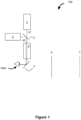
- Display device 100 comprises a first image source 1 and a second image source 2.
- Each of these image sources is able to generate and output light signals, respectively s1, s2, bearing imagery such as virtual images. These signals are output towards a combiner element 3.
- the first light output signal s1 is associated with a first, nearer, focal depth 6, and the second light output signal s2 is associated with a second, focal depth 7 different to the first.
- This difference can be achieved in a number of different ways.
- the stand-off distance between the respective image sources and the combiner element 3 could be different.
- the focal length could be determined by a the image source and the output light generated.
- the first and second focal lengths are fixed.
- the nearer focal depth may be configured to be half to 2 metres ahead of the user.
- the second focal depth may be configured to be at infinity.
- the first image source 1 is arranged generally perpendicular to the second image source 2.
- the combiner element 3 is semi-reflective, semi-transmissive and is arranged to receive light output from the first and second source.
- the combiner 3 is inclined at 45 degrees to the output light from each of the sources. (Other forms of partially-reflective, partially-transmissive combiner elements could be used in alternate embodiments).
- light from the first image source 1 is transmitted through the combiner element 3 whereas light from the second image source 2 is reflected through 90 degrees. Accordingly, the light signals s1 output by the first image source 1 are combined with the light signals s2 from the second image source 2 at the semi-reflective combiner element 3.
- relay optics 4 being a set of lenses arranged in series to condition the combined beam.
- the appropriate conditioning of the beam and hence the appropriate configuration of the relay optics 4 would be apparent to the skilled optic designer.
- the relay optics 4 output the combined, conditioned light to a second combiner element 5, which is partially-reflective and partially-transmissive.
- the combiner element 5 will be integrated into a visor or eyepiece or pair of eyepieces for positioning in a user's view.
- the combiner element 5 is configured to receive the combined, conditioned light and reflect at least a portion of such into the eye of a user. As shown for this example, the user's boresight view is perpendicular to the output from the relay optics 4 and the combiner element is inclined at 45 degrees to the output from the relay optics 4 and positioned on the user's boresight view.
- the virtual images carried by the light signal s1 output by image source 1 and the virtual images carried by the light signal s2 output by the image source 2 are presented to the user.
- the second combiner 5 is partially reflected and partially transmissive. As such, the user is able to see the virtual images superimposed on the user's ambient view.
- the user Given the respective focal depths of the light signals (s1, s2) and the respective virtual images they bear, the user will perceive the virtual images at one of two focal depths: a nearer focal depth 6 and a farther focal depth 7.
- the first image source 1 generates virtual images for a nearer focal depth 6
- second image source 2 generates virtual images for the farther focal depth 7.
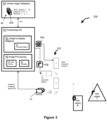
- FIG 2 and Figure 3 set out an example display system 200 utilising the display device 100. (For ease of viewing not all components of the system are shown in Figure 3 ).
- the system 200 comprises the display device 100, a virtual image database 40, a processing unit 50 and a camera device 10.
- the virtual image database 40 stores electronically a number of virtual images (43a, b,..., n) and accompanying metadata.
- each virtual image may be listed alongside a particular target real-world object (T, R, S... m), and/or a particular real-world region (302, 304, ...,p), and/or a particular focal depth (near, far, ..., q) as an image data set 42.
- the camera device 10 may be one or more cameras.
- the camera device 10 is arranged to substantially view the same ambient scene as the user, and generate ambient imaging data (AID).
- the processing unit 50 comprises an image-to-display mapping module 52 and an image processing module 56.
- the processing unit 50 is operably connected to the virtual image database 40 and the camera device 10 such that it can receive image data sets 42 and AID respectively. Further, the processing unit 50 is operably connected to both the first image source 1 and the second image source 2 such that it may address appropriate imagery-bearing signals to each.
- the image-to-display mapping unit 52 comprises a transformation 53 submodule, which may be used to apply a scaling, rotation or skewing to virtual images.
- the Image processing module 56 comprises an image recognition 57 submodule and a ranging 58 submodule.
- the camera device 10 comprises a left camera 22 and a right camera 24.
- Left camera generates first camera data (CD1) and right camera generates second camera data (CD2).
- CD1 and CD2 combined represent AID.
- the display system 200 is at least partially arranged on a mount structure or frame 26 having the form of a head worn structure e.g. a pair of glasses or goggles.
- a mount structure or frame 26 having the form of a head worn structure e.g. a pair of glasses or goggles.
- the mount tends to comprise arms for resting on the users ears, linked by a member where eyepieces may be mounted, and a bridge to rest on the user's nose.
- head worn structures are contemplated and would include helmet mounted structures).
- the left and right cameras 22, 24 are mounted on the left and right outermost sides of the mount structure 26, separated by dimension 500.
- the mount structure accommodates the second combiner 5.
- the second combiner 5 is shown as a pair of eyepieces, one for each eye. In alternative embodiments, the second combiner may be a single visor member.
- the eyepieces are located on the mount 26 in between the left 22 and right camera 24.
- Left camera 22 defines a separation 501 between itself and the left eye.
- Right eye 24 defines a separation of 502 between itself and the right eye.
- the mount structure 26 is arranged such that when worn at the users head, the combiners 5 are positioned over the user's eyes.
- the left camera 22 has a field of view ABC.
- the right camera 24 has a field of view DEF.
- the fields of view of the left and right cameras overlap at a common portion BDG.
- the nearest point of the common portion to the user is point G.
- the system is be configured to have a minimal separation between point G and the user, thereby covering substantially the user's field of view.
- the users left eye has a field of view IHK and the right eye IHL. There is an overlap in the region IHJ where the user would have binocular vision.
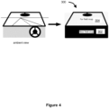
- Figure 4 shows a view of an ambient scene in which the display system 200 may be used.
- Figure 4 shows an ambient scene a user may view while sat in a car.
- the scene has a distinct internal zone (including the dashboard, driving wheel, read view mirror and windscreen frame) and a distinct outside view (including the road and road side).
- This ambient scene may be converted into a map 300 comprising a near field zone 302 and a far field zone 304.
- a near field display of virtual images is preferable and for the far field zone 304 a far field display of virtual images is preferable.
- the display system 200 is able to recognise objects (e.g. R, T, S) or zones (304, 302) in a scene and then match predetermined virtual objects to the respective objects or zones according to predetermined rules.
- objects e.g. R, T, S
- zones 304, 302
- certain virtual images are to be presented at a near focal length and others are to be presented at a far focal length.
- a user may wear the display system 200 and view an ambient scene.
- Objects T, S and I are present in the scene.
- Figure 4 shows such an arrangement where a vehicle cockpit/dashboard represents a first zone, near field map 302, and the outside scene the second zone, far field map 304.
- the user In viewing the ambient scene, the user directs cameras 22, 24 towards the scene and imaging data (AID) is generated by the cameras and sent to the processing unit 50.
- AID imaging data
- the imaging data (AID) is received by the processing unit 50 and directed to the image processing module 56.
- the AID is used by an image recognition module 57 which scans the data for objects or zones of interest. Such zones or objects will generally have been pre-defined in accordance with the intended use of the system.
- the image recognition module 57 may generate a signal indicating the presence (e.g. yes or no), and direction (e.g. as a bearing), of an object (or zone) in the scene.
- a ranging module 58 may use the AID to determine the distance to the recognised object or zone. Such ranging may be performed using standard rangefinder geometrical techniques, parallax determinations, or may use alternative methods (see the discussion of Figure 5 below).
- the processing unit 50 may generate a signal denoting the presence, and location (e.g. bearing and range) of a particular object or zone.
- the processor unit 50 can address this presence/location signal to the image-to-display mapping module 52.
- the mapping module 52 making reference to the virtual image database 40, uses the presence/location signal to select any appropriate virtual image that is to be associated with the object/zone.
- mapping module 52 uses the presence/location signal to determine a focal depth for the virtual image.
- the processing unit 50 can address the virtual image, as a suitable signal, to the relevant image source 1 or 2.
- a speedometer reading is to be presented as a virtual image 43a on the dashboard at the near focal length 6
- a directional arrow e.g. for navigation
- a virtual image 43b is to appear centrally in the windscreen at the far focal length 7.
- the image processing module 56 recognises in the AID the dashboard, then the presence/location signal will be used by the mapping module 52 to select the speedometer virtual image 43a and address it to the near depth projector 1.
- the image processing module 56 recognises in the AID the windscreen, then the presence/location signal will be used by the mapping module 52 to select the directional arrow virtual image 43b and address it to the far depth projector 2.
- Figure 5 illustrates steps in a process for determining the range of an object, such as may be used with the system 200.
- Box 522 represents an image captured at a certain instant by left camera 22 (as such box 522 represents camera data, CD1).
- Box 425 represents an image captured at that same instance by right camera 24 (as such box 425 represents camera data, C2).
- object S is relatively close to the imaging devices 22, 24, which are set apart by separation 500.
- the location of object S is different in each of the images 522 and 524. Accordingly an offset 530 representing the camera-to-camera discrepancy of close objects is defined.
- this offset can be used to estimate a specific value for the range to the object S e.g. through use of a look up table.
- the location of S can be taken as the average position of S between the two images. (This assumes that the left and right cameras are mounted at the same distance from the centre of the users field of view). As shown in Figure 3 , the separation 501 between the left eye and the left camera is equal to separation 502 between the right eye and the right camera. (Of course if there were differences between separation 501 and separation 502, then an aggregated position of the object S, for the purposes of superimposing virtual images, could be calculated taking by taking a corresponding weighted average of the positions).
- a still further use for the offset 530 is in addressing virtual images to either image source 1 or 2 without having to determine a specific range to the associated object. For example if the offset 530 for an object S is above a predetermined threshold, it may be determined that any virtual images mapped to the object should be sent to the first image source 1 for near focal depth display. Conversely, is the offset is below the predetermined threshold, it may be determined that any virtual images mapped to that object should be sent to the second image source 2 for far focal depth display. Such a further use could find particular utility where particular objects or zones are likely to shift between the near field and the far field.
- the camera device 10 has been used both as a ranging device and as an imaging device. In alternative examples, it may be possible to provide a ranging device which is separate from an imaging device.
- the display device and system may be provided at a helmet.
- the helmet may be for use in managing or controlling a vehicle, especially an aircraft.
Landscapes
- Engineering & Computer Science (AREA)
- Multimedia (AREA)
- Signal Processing (AREA)
Priority Applications (4)
| Application Number | Priority Date | Filing Date | Title |
|---|---|---|---|
| EP23275072.9A EP4459983A1 (de) | 2023-05-03 | 2023-05-03 | System zur anzeige virtueller bilder |
| EP24725000.4A EP4706241A1 (de) | 2023-05-03 | 2024-04-30 | System zur anzeige virtueller bilder |
| PCT/GB2024/051140 WO2024228014A1 (en) | 2023-05-03 | 2024-04-30 | System for displaying virtual images |
| TW113116502A TW202501213A (zh) | 2023-05-03 | 2024-05-03 | 顯示虛像的系統 |
Applications Claiming Priority (1)
| Application Number | Priority Date | Filing Date | Title |
|---|---|---|---|
| EP23275072.9A EP4459983A1 (de) | 2023-05-03 | 2023-05-03 | System zur anzeige virtueller bilder |
Publications (1)
| Publication Number | Publication Date |
|---|---|
| EP4459983A1 true EP4459983A1 (de) | 2024-11-06 |
Family
ID=86329178
Family Applications (1)
| Application Number | Title | Priority Date | Filing Date |
|---|---|---|---|
| EP23275072.9A Pending EP4459983A1 (de) | 2023-05-03 | 2023-05-03 | System zur anzeige virtueller bilder |
Country Status (1)
| Country | Link |
|---|---|
| EP (1) | EP4459983A1 (de) |
Citations (2)
| Publication number | Priority date | Publication date | Assignee | Title |
|---|---|---|---|---|
| WO2015192117A1 (en) * | 2014-06-14 | 2015-12-17 | Magic Leap, Inc. | Methods and systems for creating virtual and augmented reality |
| WO2023048822A1 (en) * | 2021-09-26 | 2023-03-30 | Microsoft Technology Licensing, Llc | Combined birefringent material and reflective waveguide for multiple focal planes in a mixed-reality head-mounted display device |
-
2023
- 2023-05-03 EP EP23275072.9A patent/EP4459983A1/de active Pending
Patent Citations (2)
| Publication number | Priority date | Publication date | Assignee | Title |
|---|---|---|---|---|
| WO2015192117A1 (en) * | 2014-06-14 | 2015-12-17 | Magic Leap, Inc. | Methods and systems for creating virtual and augmented reality |
| WO2023048822A1 (en) * | 2021-09-26 | 2023-03-30 | Microsoft Technology Licensing, Llc | Combined birefringent material and reflective waveguide for multiple focal planes in a mixed-reality head-mounted display device |
Similar Documents
| Publication | Publication Date | Title |
|---|---|---|
| US12054047B2 (en) | Image processing method of generating an image based on a user viewpoint and image processing device | |
| US7961117B1 (en) | System, module, and method for creating a variable FOV image presented on a HUD combiner unit | |
| US8253653B2 (en) | Image observation system | |
| US12198399B2 (en) | Display system and display method | |
| US11048095B2 (en) | Method of operating a vehicle head-up display | |
| US20010048763A1 (en) | Integrated vision system | |
| US20170060235A1 (en) | Method of operating a vehicle head-up display | |
| US20210152812A1 (en) | Display control device, display system, and display control method | |
| CN113655618A (zh) | 一种基于双目视觉的arhud图像显示方法和装置 | |
| US10412378B2 (en) | Resonating optical waveguide using multiple diffractive optical elements | |
| US20220013046A1 (en) | Virtual image display system, image display method, head-up display, and moving vehicle | |
| US10642038B1 (en) | Waveguide based fused vision system for a helmet mounted or head worn application | |
| JP2021067909A (ja) | 立体表示装置及びヘッドアップディスプレイ装置 | |
| JP2021110904A (ja) | ヘッドアップディスプレイ装置 | |
| WO2023119266A1 (en) | Display of augmented reality images using a virtual optical display system | |
| EP4459983A1 (de) | System zur anzeige virtueller bilder | |
| EP4459360A1 (de) | Anzeigevorrichtung für ein benutzermontierbares anzeigesystem | |
| EP4459359A1 (de) | Benutzermontierbares anzeigesystem und verfahren | |
| EP4706241A1 (de) | System zur anzeige virtueller bilder | |
| GB2629593A (en) | System for displaying virtual images | |
| EP4705824A1 (de) | Benutzermontierbares anzeigesystem und verfahren | |
| WO2024228015A1 (en) | Display device for a user-mountable display system | |
| GB2629592A (en) | User-mountable display system and method | |
| GB2631378A (en) | Display device for a user-mountable display system | |
| US11780368B2 (en) | Electronic mirror system, image display method, and moving vehicle |
Legal Events
| Date | Code | Title | Description |
|---|---|---|---|
| PUAI | Public reference made under article 153(3) epc to a published international application that has entered the european phase |
Free format text: ORIGINAL CODE: 0009012 |
|
| STAA | Information on the status of an ep patent application or granted ep patent |
Free format text: STATUS: THE APPLICATION HAS BEEN PUBLISHED |
|
| AK | Designated contracting states |
Kind code of ref document: A1 Designated state(s): AL AT BE BG CH CY CZ DE DK EE ES FI FR GB GR HR HU IE IS IT LI LT LU LV MC ME MK MT NL NO PL PT RO RS SE SI SK SM TR |