EP4459964A1 - Elektronische vorrichtung - Google Patents
Elektronische vorrichtung Download PDFInfo
- Publication number
- EP4459964A1 EP4459964A1 EP22914845.7A EP22914845A EP4459964A1 EP 4459964 A1 EP4459964 A1 EP 4459964A1 EP 22914845 A EP22914845 A EP 22914845A EP 4459964 A1 EP4459964 A1 EP 4459964A1
- Authority
- EP
- European Patent Office
- Prior art keywords
- display screen
- device body
- electronic device
- rotating shaft
- shaft
- Prior art date
- Legal status (The legal status is an assumption and is not a legal conclusion. Google has not performed a legal analysis and makes no representation as to the accuracy of the status listed.)
- Pending
Links
Images




Classifications
-
- G—PHYSICS
- G09—EDUCATION; CRYPTOGRAPHY; DISPLAY; ADVERTISING; SEALS
- G09F—DISPLAYING; ADVERTISING; SIGNS; LABELS OR NAME-PLATES; SEALS
- G09F9/00—Indicating arrangements for variable information in which the information is built-up on a support by selection or combination of individual elements
- G09F9/30—Indicating arrangements for variable information in which the information is built-up on a support by selection or combination of individual elements in which the desired character or characters are formed by combining individual elements
- G09F9/301—Indicating arrangements for variable information in which the information is built-up on a support by selection or combination of individual elements in which the desired character or characters are formed by combining individual elements flexible foldable or roll-able electronic displays, e.g. thin LCD, OLED
-
- F—MECHANICAL ENGINEERING; LIGHTING; HEATING; WEAPONS; BLASTING
- F16—ENGINEERING ELEMENTS AND UNITS; GENERAL MEASURES FOR PRODUCING AND MAINTAINING EFFECTIVE FUNCTIONING OF MACHINES OR INSTALLATIONS; THERMAL INSULATION IN GENERAL
- F16H—GEARING
- F16H7/00—Gearings for conveying rotary motion by endless flexible members
- F16H7/02—Gearings for conveying rotary motion by endless flexible members with belts; with V-belts
- F16H7/023—Gearings for conveying rotary motion by endless flexible members with belts; with V-belts with belts having a toothed contact surface or regularly spaced bosses or hollows for slipless or nearly slipless meshing with complementary profiled contact surface of a pulley
-
- G—PHYSICS
- G06—COMPUTING OR CALCULATING; COUNTING
- G06F—ELECTRIC DIGITAL DATA PROCESSING
- G06F1/00—Details not covered by groups G06F3/00 - G06F13/00 and G06F21/00
- G06F1/16—Constructional details or arrangements
-
- G—PHYSICS
- G06—COMPUTING OR CALCULATING; COUNTING
- G06F—ELECTRIC DIGITAL DATA PROCESSING
- G06F1/00—Details not covered by groups G06F3/00 - G06F13/00 and G06F21/00
- G06F1/16—Constructional details or arrangements
- G06F1/1613—Constructional details or arrangements for portable computers
- G06F1/1615—Constructional details or arrangements for portable computers with several enclosures having relative motions, each enclosure supporting at least one I/O or computing function
- G06F1/1616—Constructional details or arrangements for portable computers with several enclosures having relative motions, each enclosure supporting at least one I/O or computing function with folding flat displays, e.g. laptop computers or notebooks having a clamshell configuration, with body parts pivoting to an open position around an axis parallel to the plane they define in closed position
-
- G—PHYSICS
- G06—COMPUTING OR CALCULATING; COUNTING
- G06F—ELECTRIC DIGITAL DATA PROCESSING
- G06F1/00—Details not covered by groups G06F3/00 - G06F13/00 and G06F21/00
- G06F1/16—Constructional details or arrangements
- G06F1/1613—Constructional details or arrangements for portable computers
- G06F1/1633—Constructional details or arrangements of portable computers not specific to the type of enclosures covered by groups G06F1/1615 - G06F1/1626
- G06F1/1637—Details related to the display arrangement, including those related to the mounting of the display in the housing
- G06F1/1652—Details related to the display arrangement, including those related to the mounting of the display in the housing the display being flexible, e.g. mimicking a sheet of paper, or rollable
-
- G—PHYSICS
- G06—COMPUTING OR CALCULATING; COUNTING
- G06F—ELECTRIC DIGITAL DATA PROCESSING
- G06F1/00—Details not covered by groups G06F3/00 - G06F13/00 and G06F21/00
- G06F1/16—Constructional details or arrangements
- G06F1/1613—Constructional details or arrangements for portable computers
- G06F1/1633—Constructional details or arrangements of portable computers not specific to the type of enclosures covered by groups G06F1/1615 - G06F1/1626
- G06F1/1675—Miscellaneous details related to the relative movement between the different enclosures or enclosure parts
- G06F1/1681—Details related solely to hinges
-
- G—PHYSICS
- G09—EDUCATION; CRYPTOGRAPHY; DISPLAY; ADVERTISING; SEALS
- G09F—DISPLAYING; ADVERTISING; SIGNS; LABELS OR NAME-PLATES; SEALS
- G09F9/00—Indicating arrangements for variable information in which the information is built-up on a support by selection or combination of individual elements
- G09F9/30—Indicating arrangements for variable information in which the information is built-up on a support by selection or combination of individual elements in which the desired character or characters are formed by combining individual elements
-
- H—ELECTRICITY
- H04—ELECTRIC COMMUNICATION TECHNIQUE
- H04M—TELEPHONIC COMMUNICATION
- H04M1/00—Substation equipment, e.g. for use by subscribers
- H04M1/02—Constructional features of telephone sets
-
- H—ELECTRICITY
- H04—ELECTRIC COMMUNICATION TECHNIQUE
- H04M—TELEPHONIC COMMUNICATION
- H04M1/00—Substation equipment, e.g. for use by subscribers
- H04M1/02—Constructional features of telephone sets
- H04M1/0202—Portable telephone sets, e.g. cordless phones, mobile phones or bar type handsets
- H04M1/0206—Portable telephones comprising a plurality of mechanically joined movable body parts, e.g. hinged housings
- H04M1/0208—Portable telephones comprising a plurality of mechanically joined movable body parts, e.g. hinged housings characterized by the relative motions of the body parts
- H04M1/0214—Foldable telephones, i.e. with body parts pivoting to an open position around an axis parallel to the plane they define in closed position
- H04M1/0216—Foldable in one direction, i.e. using a one degree of freedom hinge
-
- H—ELECTRICITY
- H04—ELECTRIC COMMUNICATION TECHNIQUE
- H04M—TELEPHONIC COMMUNICATION
- H04M1/00—Substation equipment, e.g. for use by subscribers
- H04M1/02—Constructional features of telephone sets
- H04M1/0202—Portable telephone sets, e.g. cordless phones, mobile phones or bar type handsets
- H04M1/0206—Portable telephones comprising a plurality of mechanically joined movable body parts, e.g. hinged housings
- H04M1/0208—Portable telephones comprising a plurality of mechanically joined movable body parts, e.g. hinged housings characterized by the relative motions of the body parts
- H04M1/0214—Foldable telephones, i.e. with body parts pivoting to an open position around an axis parallel to the plane they define in closed position
- H04M1/0216—Foldable in one direction, i.e. using a one degree of freedom hinge
- H04M1/022—The hinge comprising two parallel pivoting axes
-
- H—ELECTRICITY
- H04—ELECTRIC COMMUNICATION TECHNIQUE
- H04M—TELEPHONIC COMMUNICATION
- H04M1/00—Substation equipment, e.g. for use by subscribers
- H04M1/02—Constructional features of telephone sets
- H04M1/0202—Portable telephone sets, e.g. cordless phones, mobile phones or bar type handsets
- H04M1/026—Details of the structure or mounting of specific components
- H04M1/0266—Details of the structure or mounting of specific components for a display module assembly
- H04M1/0268—Details of the structure or mounting of specific components for a display module assembly including a flexible display panel
Definitions
- This application relates to the field of communication technologies, and specifically, to an electronic device.
- a display screen size of an electronic device is getting larger and larger.
- the larger display screen can not only improve aesthetics of the electronic device, but also bring better visual impact to users, thereby improving user experience of the electronic device.
- a display screen of the electronic device is a flexible display screen, and a size of a display area can be changed by folding and unfolding the electronic device, so that a larger display area can be obtained, and a size of the electronic device can be reduced by folding the electronic device, thereby making it easier for the user to carry.
- An objective of embodiments of this application is to provide an electronic device that can resolve the problem of the short lifespan of the flexible display screen.
- Embodiments of this application provide an electronic device, including a first device body, a second device body, a rotating mechanism, and a flexible display screen, and the flexible display screen includes a first display screen, a second display screen, and a third display screen.
- the first device body is rotationally connected to the second device body through the rotating mechanism.
- the first display screen is connected to the second display screen through the third display screen.
- the first device body is connected to the first display screen, and the second device body is connected to the second display screen.
- the rotating mechanism includes a rotating shaft, a transmission apparatus, and a moving component, the moving component is equipped with a first transmission tooth that meshes with the transmission apparatus, the rotating shaft is connected to the moving component through the transmission apparatus, and at least one of the first device body and second device body is connected to the moving component.
- the first device body and the second device body can rotate relative to each other, so that the electronic device switches between a folded state and an unfolded state, and in a case that the electronic device switches from the folded state to the unfolded state, the rotating shaft drives the moving component away from the rotating shaft through the transmission apparatus; or in a case that the electronic device switches from the unfolded state to the folded state, the rotating shaft drives, through the transmission apparatus, the moving component to approach the rotating shaft.
- the rotating shaft in a case that the electronic device switches from the folded state to the unfolded state, may drive the moving component away from the rotating shaft through the transmission apparatus, so that a support length of the first device body and the second device body for the flexible display screen becomes larger, to prevent the flexible display screen from being wrinkled and delaminated due to excessive squeezing; and in a case that the electronic device switches from the unfolded state to the folded state, the rotating shaft drives, through the transmission apparatus, the moving component to approach the rotating shaft, so that the support length of the first device body and the second device body for the flexible display screen becomes smaller, to prevent the flexible display screen from being broken due to excessive pulling.
- the first device body and the second device body can move relative to the rotating shaft with the folding or unfolding of the electronic device, so that the flexible display screen is not damaged due to the folding or unfolding of the electronic device, and therefore, the flexible display screen has a longer lifespan.
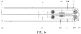
- Embodiments of this application disclose an electronic device, including a first device body 110, a second device body 120, a rotating mechanism 300, and a flexible display screen 400.
- the first device body 110 and the second device body 120 may serve as basic parts of the electronic device, thereby providing an installation foundation for the flexible display screen 400, circuit boards, batteries and other components.
- the first device body 110 and the second device body 120 each may include components such as a frame and a mainboard upper cover connected to the frame.
- the first device body 110 is rotationally connected to the second device body 120 through the rotating mechanism 300.
- the first device body 110 and the second device body 120 may rotate relative to each other, so that the electronic device switches between a folded state and an unfolded state. In other words, during the process of folding or unfolding the electronic device, the first device body 110 and the second device body 120 may rotate relative to each other.
- a display area of the flexible display screen 400 is larger, thereby satisfying user's requirement for a large display screen; or in a case that the electronic device is in the folded state, an overall size of the electronic device is smaller, making it easier for the user to carry and hold the electronic device.
- the flexible display screen 400 includes a first display screen 410, a second display screen 420, and a third display screen 430.
- the first display screen 410 is connected to the second display screen 420 through the third display screen 430, so that the three can be fixedly spliced into a complete display area. It is clear that, the first display screen 410, the second display screen 420, and the third display screen 430 may alternatively be displayed independently.
- the first device body 110 may be connected to the first display screen 410 in bonding or other manners, and the second device body 120 can be connected to the second display screen 420 in bonding or other manners.
- the first display screen 410 and the second display screen 420 may rotate relative to each other, and the third display screen 430 may be deformed to adapt to an angle change between the first display screen 410 and the second display screen 420.
- the flexible display screen 400 may be an external foldable display screen. To be specific, in a case that the electronic device is in the folded state, the first device body 110 and the second device body 120 are both located between the first display screen 410 and the second display screen 420, in this case, the first device body 110 and the second device body 120 are located within space enclosed by the flexible display screen 400.
- the flexible display screen 400 may alternatively be an internal foldable display screen. To be specific, in a case that the electronic device is in the folded state, the first display screen 410 and the second display screen 420 are both located between the first device body 110 and the second device body 120, in this case, the first display screen 410 and the second display screen 420 are located in space between the first device body 110 and the second device body 120.
- the flexible display screen 400 when the flexible display screen 400 is an internal foldable display screen, in a case that the electronic device is in the folded state, the flexible display screen 400 is prone to creases due to extrusion of the first device body 110 and the second device body 120. In addition, dust and other particles in an external environment may easily enter the electronic device or the flexible display screen 400 due to an inability of the flexible display screen 400 to fit completely. In a case that the flexible display screen 400 is an external foldable display screen, the first device body 110 and the second device body 120 basically do not squeeze the flexible display screen 400, and therefore, the flexible display screen 400 is less prone to creases.
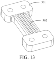
- the rotating mechanism 300 includes a rotating shaft, a transmission apparatus 310, and a moving component 301, the moving component 301 is equipped with a first transmission tooth 302 that meshes with the transmission apparatus 310, the rotating shaft is connected to the moving component 301 through the transmission apparatus 310, and at least one of the first device body 110 and the second device body 120 is connected to the moving component 301.
- the transmission apparatus 310 can be connected to the first device body 110 through the moving component 301; or the transmission apparatus 310 is connected to the second device body 120 through the moving component 301; or at least one transmission apparatus 310 is connected to the first device body 110 through at least one moving component 301, and at the same time, at least one other transmission apparatus 310 is connected to the first device body 110 through at least one other moving component 301.
- the first device body 110 and the second device body 120 may rotate around the rotating shaft, at the same time, the transmission apparatus 310 can transmit force outputted by the rotating shaft to at least one of the first device body 110 and the second device body 120 through the moving component 301, so that at least one of the first device body 110 and the second device body 120 can move under a trigger of the folding operation or the unfolding operation.
- At least one of the first device body 110 and the second device body 120 may be defined as a target device body.
- a distance of the target device body relative to the rotating shaft may dynamically change, and the distance between the target device body and the rotating shaft may be defined as a first distance.
- the first distance changes as an included angle between the first device body 110 and the second device body 120 changes, and the change of the included angle causes a change in a bending angle of the flexible display screen 400, there is a correspondence between the first distance and the bending angle of the flexible display screen 400.
- the first transmission tooth 302 equipped on the moving component 301 may be a strip groove.
- a number of strip grooves is at least two, the strip grooves may be arranged in parallel, and each strip groove may extend in a direction parallel to the rotating shaft.
- the transmission apparatus 310 is equipped with a structure that meshes with the strip groove to transmit the force.
- the moving component 301 may be fixedly connected to the first device body 110 or the second device body 120 through connection structures such as a screw 391.
- Only one transmission apparatus 310 and one moving component 301 may be equipped.
- the rotating shaft is transmission connected only to the first device body 110 or the second device body 120 through the transmission apparatus 310 and the moving component 301.
- at least two transmission apparatuses 310 and at least two moving component 301 are equipped, and the rotating shaft is transmission connected to the first device body 110 through at least one transmission apparatus 310 and at least one moving component 301, while the rotating shaft is transmission connected to the second device body 120 through at least one other transmission apparatus 310 and at least one other moving component 301.
- the number of the moving components 301 is at least two, including a first moving component 320 and a second moving component 330.
- the rotating shaft is connected to the first moving component 320 through at least one transmission apparatus 310, and the rotating shaft is connected to the second moving component 330 through at least one other transmission apparatus 310.
- the first moving component 320 is connected to the first device body 110, and the second moving component 330 is connected to the second device body 120.
- the first moving component 320 may be fixedly connected to the first device body 110 through connection structures such as the screw 391
- the second moving component 330 may also be fixedly connected to the second device body 120 through connection structures such as the screw 391.
- the first moving component 320 and the second moving component 330 may both adopt a bar structure, and may both be parallel to the rotating shaft, thereby facilitating a layout design of the electronic device.
- the rotating shaft drives the first moving component 320 and the second moving component 330 away from the rotating shaft through the transmission apparatus 310; or in a case that the electronic device switches from the unfolded state to the folded state, the rotating shaft drives, through the transmission apparatus 310, the first moving component 320 and the second moving component 330 to approach the rotating shaft.
- the rotating shaft may be transmission connected to the first device body 110 through at least two transmission apparatuses 310 and at least two first moving components 320 at the same time.
- the rotating shaft may be transmission connected to the second device body 120 through at least two transmission apparatuses 310 and at least two second moving components 330 at the same time, thereby improving connection reliability.
- a number of each of the transmission apparatuses 310, the first moving components 320, and the second moving components 330 is at least two, specific structures of all transmission apparatuses 310, all first moving components 320, and all second moving components 330 may be the same or different. This is not limited in embodiments of this application.
- the rotating shaft drives the moving component 301 away from the rotating shaft through the transmission apparatus 310.
- at least one of the first device body 110 and the second device body 120 is away from the rotating shaft, so that a support length of the first device body 110 and the second device body 120 for the flexible display screen 400 becomes larger, to prevent the third display screen 430 of the flexible display screen 400 from being wrinkled and delaminated due to excessive squeezing.
- the rotating shaft drives, through the transmission apparatus 310, the moving component 301 to approach the rotating shaft.
- At least one of the first device body 110 and the second device body 120 is close to the rotating shaft, so that the support length of the first device body 110 and the second device body 120 for the flexible display screen 400 becomes smaller, to prevent the third display screen 430 of the flexible display screen from being broken due to excessive pulling. It can be seen that the first device body 110 and the second device body 120 can move relative to the rotating shaft with the folding or unfolding of the electronic device, so that the flexible display screen 400 is not damaged due to the folding or unfolding of the electronic device, and therefore, the flexible display screen 400 has a longer lifespan.
- a number of the rotating shafts may be at least two, including a first shaft 210 and a second shaft 220.
- the first shaft 210 and the second shaft 220 may be parallel to each other.
- the first shaft 210 may be connected to the first moving component 320 through at least one transmission apparatus 310, thereby being connected to the first device body 110, and the second shaft 220 may be connected to the second moving component 330 through at least one transmission apparatus 310, thereby being connected to the second device body 120.
- the first shaft 210 drives the first device body 110 away from the rotating shaft through the transmission apparatus 310 and the first moving component 320, and the second shaft 220 drives the second device body 120 away from the rotating shaft through the transmission apparatus 310 and the second moving component 330.
- the first shaft 210 drives, through the transmission apparatus 310 and the first moving component 320, the first device body 110 to approach the rotating shaft
- the second shaft 220 drives, through the transmission apparatus 310 and the second moving component 330, the second device body 120 to approach the rotating shaft.
- the rotating mechanism 300 includes a rotating shaft bracket 350.
- the rotating shaft bracket 350 is equipped with a first hole and a second hole. One end of the first shaft 210 passes through the first hole, and one end of the second shaft 220 passes through the second hole. In other words, the first shaft 210 can be connected to the second shaft 220 through the rotating shaft bracket 350.
- the rotating shaft bracket 350 is equipped with an arc-shaped support surface 351, and in a case that the electronic device is in the folded state, the arc-shaped support surface 351 faces the third display screen 430.
- the arc-shaped support surface 351 may contact the third display screen 430, thereby supporting the third display screen 430; alternatively, there may be a small gap between the arc-shaped support surface 351 and the third display screen 430, and when the third display screen 430 is pressed, the arc-shaped support surface 351 contacts the third display screen 430, thereby supporting the third display screen 430.
- the rotating shaft bracket 350 can connect the first shaft 210 and the second shaft 220, and support the third display screen 430 in an appropriate occasion, thereby improving flatness of the third display screen 430, facilitating user's touch operation and protecting the third display screen 430.
- the arc-shaped support surface 351 equipped on the rotating shaft bracket 350 may be a concave surface, the concave surface is concaved in a direction away from the third display screen 430, thereby increasing a support area of the arc-shaped support surface 351 for the third display screen 430.
- the arc-shaped support surface 351 equipped on the rotating shaft bracket 350 may be a convex surface, the convex surface protrudes in a direction toward the third display screen 430, thereby increasing a support area of the arc-shaped support surface 351 for the third display screen 430.
- the rotating mechanism further includes a support plate 340, and a number of support plates 340 is at least two. At least one support plate 340 is connected to the first shaft 210, and at least one other support plate 340 is connected to the second shaft 220.
- a support plate 340 connected to the first shaft 210 includes a first gear portion 341, and a support plate 340 connected to the second shaft 220 includes a second gear portion 342.
- the first gear portion 341 is sleeved on the first shaft 210
- the second gear portion 342 is sleeved on the second shaft
- the first gear portion 341 meshes with the second gear portion 342.
- the support plate 340 connected to the first shaft 210 may further include a portion that is slidably connected to the first device body 110
- the support plate 340 connected to the second shaft 220 may further include a portion that is slidably connected to the second device body 120.
- the first device body 110 can rotate relative to the second device body 120, and the first gear portion 341 and the second gear portion 342 respectively drive the first shaft 210 and the second shaft 220 to rotate synchronously. Since a transmission manner of tooth meshing is more reliable, this embodiment can improve the synchronization of the rotation of the first shaft 210 and the second shaft 220.
- the meshing between the first gear portion 341 and the second gear portion 342 may create a specific damping sense during the folding or unfolding process of the electronic device, preventing collision and other problems caused by a relative rotation speed between the first device body 110 and the second device body 120 being excessively high.
- Damping force between the first gear portion 341 and the second gear portion 342 may be optimized, so that the electronic device can be folded or unfolded relatively easily when a user applies force to the electronic device.
- the first device body 110 and the second device body 120 can remain in a target position.
- the support plate 340 may be of an integrated structure, thereby simplifying an assembly process of the electronic device. It is clear that, the support plate 340 may alternatively adopt a split structure. When an abrasion of the first gear portion 341 or the second gear portion 342 exceeds an acceptable range, only the first gear portion 341 or the second gear portion 342 may be replaced.
- the rotating mechanism 300 further includes the support plate 340
- the support plate 340 is connected to the rotating shaft, and the support plate 340 may serve as a setting basis for the transmission apparatus 310, thereby facilitating installation of the transmission apparatus 310.
- the transmission apparatus 310 may convert rotations of the rotating shaft into movements of the first device body 110 and/or the second device body 120.
- the transmission apparatus 310 may include a lead screw nut mechanism, and so on.
- the transmission apparatus includes a support shaft 311, a first gear 312, a second gear 313, and a synchronous belt 314, a first end of the support shaft 311 is connected to the support plate 340, the first gear 312 is sleeved on the rotating shaft, the second gear 313 is sleeved on the support shaft 311, the first gear 312 is transmission connected to the second gear 313 through the synchronous belt 314, and the synchronous belt 314 meshes with the moving component 301.
- the rotating shaft rotates
- the first gear 312 rotates accordingly, thereby driving the synchronous belt 314 to move.
- a motion accuracy of the synchronous belt 314 is relatively high, thereby improving a transmission accuracy when the rotating shaft drives the moving component 301 to move.
- a transmission ratio may be adjusted by adjusting structural parameters (such as a number of teeth, a diameter, and a length) of the first gear 312, the second gear 313, and the synchronous belt 314, so that a movement distance of the moving component 301 better matches the bending angle of the flexible display screen 400, thereby more effectively preventing the flexible display screen 400 from being excessively squeezed or pulled.
- the second gear 313 may be sleeved on the support shaft 311 through a bearing 392, so that a movement of the support shaft 311 and a movement of the second gear 313 are independent of each other, avoiding mutual interferences.
- An outer surface of the synchronous belt 314 may be equipped with a structure for meshing with the first transmission tooth 302; or an inner surface of the synchronous belt may be equipped with a second transmission tooth, the moving component 301 is equipped with a first surface facing the inner surface, the first surface is equipped with the first transmission tooth 302, and the second transmission tooth meshes with the first transmission tooth 302.
- a portion of the synchronous belt 314 is located between the first surface of the moving component 301 and the first device body 110 (or the second device body 120). Therefore, distribution of the synchronous belt 314 and the moving component 301 is more compact, and space occupied by both is smaller.
- the synchronous belt 314 may only be equipped with the second transmission tooth on the inner surface, the second transmission tooth may mesh with the first gear 312, the second gear 313, and the moving component 301. Therefore, a structure of the synchronous belt 314 is simpler and a structural strength of the synchronous belt 314 is higher.
- the rotating mechanism further includes a connecting rod 360.
- One end of the connecting rod 360 is sleeved on the rotating shaft, and the other end of the connecting rod 360 is sleeved on a second end of the support shaft 311.
- the second end of the support shaft 311 is connected to the rotating shaft through the connecting rod 360.
- the connecting rod 360 may apply supporting force to the second end of the support shaft 311, to prevent deformation of the support shaft 311 due to factors such as a weight of the second gear 313 and a weight of the synchronous belt 314. Therefore, the synchronous belt 314 is not easily interfered with the first device body 110 or the second device body 120 due to the deformation of the support shaft 311.
- the synchronous belt 314 may be located on a side that is of the connecting rod 360 and that is away from the support plate 340.
- the connecting rod 360 may be located between the synchronous belt 314 and the support plate 340.
- the second end of the support shaft 311 is still cantilevered, resulting in a high probability of deformation of the support shaft 311.
- the synchronous belt 314 may be equipped between the support plate 340 and the connecting rod 360.
- the connecting rod 360 can be closer to an end of the support shaft 311, so that the support shaft 311 hardly needs to be cantilevered, and the probability of the deformation of the support shaft 311 is greatly reduced.
- the connecting rod 360 may be far away from the moving component 301, to avoid the moving component 301.
- the moving component 301 may be entirely located between the connecting rod 360 and the support plate 340, but this setting will cause the transmission apparatus 310 to be excessively scattered, thereby occupying excessively large space. Therefore, to reduce the space occupied by the transmission apparatus 310, both the synchronous belt 314 and the connecting rod 360 may be located between two ends of the moving component 301. In this case, a distance between the synchronous belt 314 and the connecting rod 360 is smaller, making the transmission apparatus 310 more compact, thereby achieving the goal of reducing the space occupied by the transmission apparatus 310.
- a surface of the connecting rod 360 facing the moving component 301 is equipped with an avoidance recess 361, the avoidance recess 361 can avoid the moving component 301, making the distance between the moving component 301 and the connecting rod 360 smaller, and even a part of the moving component 301 may be located in the avoidance recess 361, thereby further reducing the space occupied by the transmission apparatus 310 moving component.
- the rotating mechanism 300 further includes the support plate 340
- the support plate 340 is connected to the rotating shaft
- the first device body 110 is equipped with a first guide part 101, and one end that is of the support plate 340 connected to the first device body 110 and that is away from the rotating shaft slidably fits with the first guide part 101
- the second device body 120 is equipped with a first guide part 101, and one end that is of the support plate 340 connected to the second device body 120 and that is away from the rotating shaft slidably fits with the first guide part 101.
- the first guide part 101 may provide guidance for movement of the support plate 340, thereby making relative rotation between the first device body 110 and the second device body 120 smoother.
- the first guide part 101 may form a specific damping sense during the folding or unfolding process of the electronic device, preventing collision and other problems caused by a relative rotation speed of the first device body 110 and the second device body 120 being excessively high.
- the rotating mechanism further includes a damper 370, and the damper 370 is equipped in the rotating shaft.
- the damper 370 may provide a damping function, thereby forming a specific damping sense during the folding or unfolding process of the electronic device, to prevent collision and other problems caused by a relative rotation speed of the first device body 110 and the second device body 120 being excessively high.
- the damper 370 may keep the first device body 110 and the second device body 120 in a target position.
- a number of dampers 370 may be at least two, with the dampers 370 arranged at intervals along an axial direction of the rotating shaft to improve a damping effect.
- the rotating shaft bracket 350 may adopt an integrated structure.
- the rotating shaft needs to be sleeved with the first gear portion 341, the second gear portion 342, and the damper 370 at the same time, and the first gear portion 341 and the second gear portion 342 are sleeved at ends of the rotating shaft, there is a gap between the damper 370 and each of the first gear portion 341 and the second gear portion 342.
- a plurality of rotating shaft brackets 350 may be equipped, and the rotating shaft brackets 350 may be arranged at intervals along the axial direction of the rotating shaft, and the damper 370 may be located between adjacent rotating shaft brackets 350.
- the first device body 110 is equipped with a second guide part 102
- the rotating mechanism further includes a guide rod 380, one end of the guide rod 380 is sleeved on the rotating shaft, and the other end of the guide rod 380 slidably fits with the second guide part 102; and/or the second device body 120 is equipped with a second guide part 102, the rotating mechanism further includes a guide rod 380, one end of the guide rod 380 is sleeved on the rotating shaft, and the other end of the guide rod 380 slidably fits with the second guide part 102.
- the guide rod 380 may be sleeved on the rotating shaft through the bearing 392 to alleviate wear between the guide rod 380 and the rotating shaft.
- the first guide part 101 may provide guidance for relative rotation between the first device body 110 and the second device body 120, thereby making the relative rotation between the first device body 110 and the second device body 120 smoother.
- the first guide part 101 may form a specific damping sense during the folding or unfolding process of the electronic device, preventing collision and other problems caused by a relative rotation speed of the first device body 110 and the second device body 120 being excessively high.
- the damper 370 may cooperate with the guide rod 380, the damper 370 may include an elastic component, and one end that is of the guide rod 380 and that is sleeved on the rotating shaft is connected to the elastic component.
- the guide rod 380 rotates relative to the damper 370, thereby applying force to the elastic component, causing the elastic component to deform and reserve elastic potential energy, and this elastic potential energy may serve as a damping power for the damper 370, enabling the damper 370 to output damping force.
- This solution does not need additional components to provide the damping power for the damper 370, thereby simplifying a structure of the electronic device and reducing costs.
- a number of the foregoing first guide parts 101 may be set to at least two, and the number of the first guide parts 101 may be equal to a number of the support plates 340, and the first guide part 101 one-to-one corresponds to the support plate 340, thereby improving a guiding effect.
- the first device body 110 may be equipped with at least two second guide parts 102, the second guide parts 102 may be arranged at intervals along an extension direction of the rotating shaft, and the second guide parts 102 may one-to-one match with a plurality of guide rods 380, thereby improving a guiding effect.
- the second device body 120 may be equipped with at least two second guide parts 102, the second guide parts 102 may be arranged at intervals along the extension direction of the rotating shaft, and the second guide part 102 may one-to-one match with a plurality of guide rods 380, thereby improving the guiding effect.
- the electronic devices disclosed in embodiments of this application may be smartphones, tablets, e-book readers, wearable devices (such as smartwatches), electronic game consoles, or other electronic devices. Types of the electronic devices are not limited in embodiments of this application.
Landscapes
- Engineering & Computer Science (AREA)
- Theoretical Computer Science (AREA)
- Computer Hardware Design (AREA)
- General Engineering & Computer Science (AREA)
- Physics & Mathematics (AREA)
- General Physics & Mathematics (AREA)
- Human Computer Interaction (AREA)
- Signal Processing (AREA)
- Mechanical Engineering (AREA)
- Mathematical Physics (AREA)
- Devices For Indicating Variable Information By Combining Individual Elements (AREA)
- Telephone Set Structure (AREA)
Applications Claiming Priority (2)
| Application Number | Priority Date | Filing Date | Title |
|---|---|---|---|
| CN202111646679.8A CN114244936B (zh) | 2021-12-29 | 2021-12-29 | 电子设备 |
| PCT/CN2022/142585 WO2023125593A1 (zh) | 2021-12-29 | 2022-12-28 | 电子设备 |
Publications (2)
| Publication Number | Publication Date |
|---|---|
| EP4459964A1 true EP4459964A1 (de) | 2024-11-06 |
| EP4459964A4 EP4459964A4 (de) | 2025-04-23 |
Family
ID=80744513
Family Applications (1)
| Application Number | Title | Priority Date | Filing Date |
|---|---|---|---|
| EP22914845.7A Pending EP4459964A4 (de) | 2021-12-29 | 2022-12-28 | Elektronische vorrichtung |
Country Status (4)
| Country | Link |
|---|---|
| US (1) | US12566478B2 (de) |
| EP (1) | EP4459964A4 (de) |
| CN (1) | CN114244936B (de) |
| WO (1) | WO2023125593A1 (de) |
Families Citing this family (5)
| Publication number | Priority date | Publication date | Assignee | Title |
|---|---|---|---|---|
| CN114244936B (zh) | 2021-12-29 | 2024-07-30 | 维沃移动通信有限公司 | 电子设备 |
| CN115681307A (zh) * | 2022-09-05 | 2023-02-03 | 武汉华星光电半导体显示技术有限公司 | 铰链、显示面板及显示装置 |
| CN115653994A (zh) * | 2022-10-09 | 2023-01-31 | 维沃移动通信有限公司 | 电子设备 |
| CN116074421A (zh) * | 2023-01-12 | 2023-05-05 | 维沃移动通信有限公司 | 电子设备 |
| CN116824986A (zh) * | 2023-06-27 | 2023-09-29 | 上海天马微电子有限公司 | 折叠装置和电子设备 |
Family Cites Families (38)
| Publication number | Priority date | Publication date | Assignee | Title |
|---|---|---|---|---|
| JPH11149328A (ja) * | 1997-11-19 | 1999-06-02 | Nec Yonezawa Ltd | 多画面パーソナルコンピュータ |
| US8854278B2 (en) * | 2003-12-19 | 2014-10-07 | Hewlett-Packard Development Company, L.P. | Display apparatus |
| US7375954B2 (en) * | 2006-04-20 | 2008-05-20 | Jun Ho Yang | Computer screen |
| US20070247798A1 (en) * | 2006-04-20 | 2007-10-25 | International Business Machines Corporation | Display having a variable display size for use in portable electronic devices and methods for controlling same |
| TWM361204U (en) * | 2008-11-18 | 2009-07-11 | Wistron Corp | Electronic device |
| US10440840B2 (en) * | 2015-09-24 | 2019-10-08 | Sharp Kabushiki Kaisha | Flexible device |
| CN105528035A (zh) * | 2015-12-31 | 2016-04-27 | 联想(北京)有限公司 | 一种电子设备 |
| TWI646369B (zh) * | 2017-09-01 | 2019-01-01 | 宏碁股份有限公司 | 顯示裝置與電子裝置 |
| TWI653524B (zh) * | 2017-12-26 | 2019-03-11 | 宏碁股份有限公司 | 具有多螢幕模組之電子裝置 |
| WO2019210728A1 (en) * | 2018-05-04 | 2019-11-07 | Guangdong Oppo Mobile Telecommunications Corp., Ltd. | Mobile terminal |
| WO2020209424A1 (ko) * | 2019-04-11 | 2020-10-15 | 엘지전자 주식회사 | 플렉서블 디스플레이 장치 |
| TWM587285U (zh) * | 2019-04-12 | 2019-12-01 | 宏碁股份有限公司 | 電子裝置 |
| TWI715023B (zh) * | 2019-04-30 | 2021-01-01 | 兆利科技工業股份有限公司 | 折疊式裝置的轉軸模組(六) |
| CN110266836B (zh) * | 2019-05-28 | 2024-08-09 | 珠海格力电器股份有限公司 | 一种屏幕折叠结构及具有其的移动终端 |
| US11416024B2 (en) * | 2019-09-18 | 2022-08-16 | Aaron BRYANT | Supplemental computing display assembly for portable computing devices |
| US10817020B1 (en) * | 2019-09-30 | 2020-10-27 | Robert Charles DeMaio | Laptop with multi-display functionality |
| CN110784567B (zh) * | 2019-10-22 | 2021-11-19 | 华为技术有限公司 | 折叠组件、折叠显示终端 |
| CN112735261A (zh) * | 2019-10-28 | 2021-04-30 | 华为技术有限公司 | 一种柔性显示屏、显示终端 |
| KR102884796B1 (ko) * | 2019-11-15 | 2025-11-12 | 삼성전자주식회사 | 폴더블 전자 장치 |
| CN113012569A (zh) * | 2019-12-19 | 2021-06-22 | 中兴通讯股份有限公司 | 一种折叠屏及折叠显示终端 |
| CN111402731B (zh) * | 2020-03-25 | 2021-05-07 | 武汉华星光电半导体显示技术有限公司 | 显示装置及显示设备 |
| CN111669455A (zh) * | 2020-05-28 | 2020-09-15 | 维沃移动通信有限公司 | 电子设备 |
| CN111681548B (zh) * | 2020-06-15 | 2021-12-28 | 武汉华星光电半导体显示技术有限公司 | 可折叠显示装置 |
| CN113849036A (zh) * | 2020-06-28 | 2021-12-28 | Oppo广东移动通信有限公司 | 电子设备及显示方法 |
| CN112216212B (zh) * | 2020-10-15 | 2022-08-26 | 京东方科技集团股份有限公司 | 中框组件、显示装置 |
| CN215068431U (zh) * | 2021-02-05 | 2021-12-07 | 苏州优智达机器人有限公司 | 一种货柜的传输机构及货柜 |
| CN112901645B (zh) * | 2021-03-01 | 2022-03-08 | 维沃移动通信有限公司 | 铰链机构和电子设备 |
| CN113163034B (zh) * | 2021-04-20 | 2023-04-21 | Oppo广东移动通信有限公司 | 壳组件和电子装置 |
| CN113163040B (zh) * | 2021-05-20 | 2023-03-14 | 维沃移动通信有限公司 | 电子设备 |
| CN113315858B (zh) * | 2021-05-31 | 2024-02-20 | 维沃移动通信有限公司 | 电子设备 |
| CN117813568A (zh) * | 2021-08-10 | 2024-04-02 | 三星电子株式会社 | 包括用于识别折叠状态的霍尔传感器的电子装置 |
| CN113794792B (zh) * | 2021-10-28 | 2024-03-26 | 维沃移动通信有限公司 | 电子设备 |
| CN114244934B (zh) * | 2021-12-29 | 2024-08-06 | 维沃移动通信有限公司 | 电子设备 |
| CN114244936B (zh) * | 2021-12-29 | 2024-07-30 | 维沃移动通信有限公司 | 电子设备 |
| CN114338875B (zh) * | 2021-12-29 | 2024-10-15 | 维沃移动通信有限公司 | 电子设备 |
| CN114244937B (zh) * | 2021-12-29 | 2024-03-22 | 维沃移动通信有限公司 | 电子设备 |
| CN114244933B (zh) * | 2021-12-29 | 2024-07-26 | 维沃移动通信有限公司 | 电子设备 |
| KR20240024404A (ko) * | 2022-08-16 | 2024-02-26 | 삼성디스플레이 주식회사 | 수납 용기 및 이를 포함하는 표시 장치 |
-
2021
- 2021-12-29 CN CN202111646679.8A patent/CN114244936B/zh active Active
-
2022
- 2022-12-28 EP EP22914845.7A patent/EP4459964A4/de active Pending
- 2022-12-28 WO PCT/CN2022/142585 patent/WO2023125593A1/zh not_active Ceased
-
2024
- 2024-06-28 US US18/757,940 patent/US12566478B2/en active Active
Also Published As
| Publication number | Publication date |
|---|---|
| US12566478B2 (en) | 2026-03-03 |
| CN114244936B (zh) | 2024-07-30 |
| CN114244936A (zh) | 2022-03-25 |
| EP4459964A4 (de) | 2025-04-23 |
| WO2023125593A1 (zh) | 2023-07-06 |
| US20240353900A1 (en) | 2024-10-24 |
Similar Documents
| Publication | Publication Date | Title |
|---|---|---|
| EP4459964A1 (de) | Elektronische vorrichtung | |
| EP4443855A1 (de) | Elektronische vorrichtung | |
| EP4199484B1 (de) | Stützstrukturelement und anzeigevorrichtung | |
| EP4459966A1 (de) | Elektronische vorrichtung | |
| EP4161227A1 (de) | Elektronische vorrichtung | |
| JP7466770B2 (ja) | 電子機器 | |
| US12398750B2 (en) | Folding mechanism and folding electronic device | |
| CN113534893B (zh) | 折叠式电子装置 | |
| CN112492780A (zh) | 电子设备 | |
| CN203759605U (zh) | 一种平板电脑 | |
| EP4461979A1 (de) | Drehmechanismus und klappbare elektronische vorrichtung | |
| CN113329109A (zh) | 电子设备 | |
| WO2023109840A1 (zh) | 电子设备 | |
| EP4325817A1 (de) | Elektronische vorrichtung | |
| WO2023125596A1 (zh) | 电子设备 | |
| CN113852701B (zh) | 电子设备及其控制方法 | |
| CN115103044A (zh) | 电子设备 | |
| CN113176810B (zh) | 电子设备 | |
| EP4546958A1 (de) | Elektronische vorrichtung | |
| CN114461023A (zh) | 电子设备 | |
| CN113851040B (zh) | 电子设备 | |
| CN111712070A (zh) | 电子设备 | |
| CN113852703B (zh) | 电子设备 | |
| CN120932545A (zh) | 一种电子设备 |
Legal Events
| Date | Code | Title | Description |
|---|---|---|---|
| STAA | Information on the status of an ep patent application or granted ep patent |
Free format text: STATUS: THE INTERNATIONAL PUBLICATION HAS BEEN MADE |
|
| PUAI | Public reference made under article 153(3) epc to a published international application that has entered the european phase |
Free format text: ORIGINAL CODE: 0009012 |
|
| STAA | Information on the status of an ep patent application or granted ep patent |
Free format text: STATUS: REQUEST FOR EXAMINATION WAS MADE |
|
| 17P | Request for examination filed |
Effective date: 20240626 |
|
| AK | Designated contracting states |
Kind code of ref document: A1 Designated state(s): AL AT BE BG CH CY CZ DE DK EE ES FI FR GB GR HR HU IE IS IT LI LT LU LV MC ME MK MT NL NO PL PT RO RS SE SI SK SM TR |
|
| DAV | Request for validation of the european patent (deleted) | ||
| DAX | Request for extension of the european patent (deleted) | ||
| A4 | Supplementary search report drawn up and despatched |
Effective date: 20250320 |
|
| RIC1 | Information provided on ipc code assigned before grant |
Ipc: G09F 9/30 20060101ALI20250314BHEP Ipc: G06F 1/16 20060101ALI20250314BHEP Ipc: H04M 1/02 20060101AFI20250314BHEP |