EP4459916A1 - Decodierungsverfahren und -vorrichtung und lesbares speichermedium - Google Patents
Decodierungsverfahren und -vorrichtung und lesbares speichermedium Download PDFInfo
- Publication number
- EP4459916A1 EP4459916A1 EP22914678.2A EP22914678A EP4459916A1 EP 4459916 A1 EP4459916 A1 EP 4459916A1 EP 22914678 A EP22914678 A EP 22914678A EP 4459916 A1 EP4459916 A1 EP 4459916A1
- Authority
- EP
- European Patent Office
- Prior art keywords
- decoder
- symbol period
- original
- encoded input
- input symbols
- Prior art date
- Legal status (The legal status is an assumption and is not a legal conclusion. Google has not performed a legal analysis and makes no representation as to the accuracy of the status listed.)
- Pending
Links
Images



Classifications
-
- H—ELECTRICITY
- H04—ELECTRIC COMMUNICATION TECHNIQUE
- H04B—TRANSMISSION
- H04B7/00—Radio transmission systems, i.e. using radiation field
- H04B7/02—Diversity systems; Multi-antenna system, i.e. transmission or reception using multiple antennas
- H04B7/04—Diversity systems; Multi-antenna system, i.e. transmission or reception using multiple antennas using two or more spaced independent antennas
- H04B7/0413—MIMO systems
- H04B7/0456—Selection of precoding matrices or codebooks, e.g. using matrices antenna weighting
- H04B7/046—Selection of precoding matrices or codebooks, e.g. using matrices antenna weighting taking physical layer constraints into account
- H04B7/0465—Selection of precoding matrices or codebooks, e.g. using matrices antenna weighting taking physical layer constraints into account taking power constraints at power amplifier or emission constraints, e.g. constant modulus, into account
-
- H—ELECTRICITY
- H04—ELECTRIC COMMUNICATION TECHNIQUE
- H04B—TRANSMISSION
- H04B7/00—Radio transmission systems, i.e. using radiation field
- H04B7/02—Diversity systems; Multi-antenna system, i.e. transmission or reception using multiple antennas
- H04B7/04—Diversity systems; Multi-antenna system, i.e. transmission or reception using multiple antennas using two or more spaced independent antennas
- H04B7/06—Diversity systems; Multi-antenna system, i.e. transmission or reception using multiple antennas using two or more spaced independent antennas at the transmitting station
- H04B7/0613—Diversity systems; Multi-antenna system, i.e. transmission or reception using multiple antennas using two or more spaced independent antennas at the transmitting station using simultaneous transmission
- H04B7/0667—Diversity systems; Multi-antenna system, i.e. transmission or reception using multiple antennas using two or more spaced independent antennas at the transmitting station using simultaneous transmission of delayed versions of same signal
- H04B7/0669—Diversity systems; Multi-antenna system, i.e. transmission or reception using multiple antennas using two or more spaced independent antennas at the transmitting station using simultaneous transmission of delayed versions of same signal using different channel coding between antennas
-
- H—ELECTRICITY
- H04—ELECTRIC COMMUNICATION TECHNIQUE
- H04L—TRANSMISSION OF DIGITAL INFORMATION, e.g. TELEGRAPHIC COMMUNICATION
- H04L1/00—Arrangements for detecting or preventing errors in the information received
- H04L1/004—Arrangements for detecting or preventing errors in the information received by using forward error control
- H04L1/0045—Arrangements at the receiver end
- H04L1/0047—Decoding adapted to other signal detection operation
-
- H—ELECTRICITY
- H04—ELECTRIC COMMUNICATION TECHNIQUE
- H04L—TRANSMISSION OF DIGITAL INFORMATION, e.g. TELEGRAPHIC COMMUNICATION
- H04L1/00—Arrangements for detecting or preventing errors in the information received
- H04L1/02—Arrangements for detecting or preventing errors in the information received by diversity reception
- H04L1/06—Arrangements for detecting or preventing errors in the information received by diversity reception using space diversity
- H04L1/0612—Space-time modulation
-
- H—ELECTRICITY
- H04—ELECTRIC COMMUNICATION TECHNIQUE
- H04L—TRANSMISSION OF DIGITAL INFORMATION, e.g. TELEGRAPHIC COMMUNICATION
- H04L1/00—Arrangements for detecting or preventing errors in the information received
- H04L1/02—Arrangements for detecting or preventing errors in the information received by diversity reception
- H04L1/06—Arrangements for detecting or preventing errors in the information received by diversity reception using space diversity
- H04L1/0618—Space-time coding
- H04L1/0631—Receiver arrangements
-
- H—ELECTRICITY
- H04—ELECTRIC COMMUNICATION TECHNIQUE
- H04L—TRANSMISSION OF DIGITAL INFORMATION, e.g. TELEGRAPHIC COMMUNICATION
- H04L1/00—Arrangements for detecting or preventing errors in the information received
- H04L1/02—Arrangements for detecting or preventing errors in the information received by diversity reception
- H04L1/06—Arrangements for detecting or preventing errors in the information received by diversity reception using space diversity
- H04L1/0618—Space-time coding
- H04L1/0637—Properties of the code
- H04L1/0668—Orthogonal systems, e.g. using Alamouti codes
-
- H—ELECTRICITY
- H04—ELECTRIC COMMUNICATION TECHNIQUE
- H04L—TRANSMISSION OF DIGITAL INFORMATION, e.g. TELEGRAPHIC COMMUNICATION
- H04L5/00—Arrangements affording multiple use of the transmission path
-
- H—ELECTRICITY
- H04—ELECTRIC COMMUNICATION TECHNIQUE
- H04L—TRANSMISSION OF DIGITAL INFORMATION, e.g. TELEGRAPHIC COMMUNICATION
- H04L5/00—Arrangements affording multiple use of the transmission path
- H04L5/0001—Arrangements for dividing the transmission path
- H04L5/0003—Two-dimensional division
-
- H—ELECTRICITY
- H04—ELECTRIC COMMUNICATION TECHNIQUE
- H04N—PICTORIAL COMMUNICATION, e.g. TELEVISION
- H04N19/00—Methods or arrangements for coding, decoding, compressing or decompressing digital video signals
- H04N19/42—Methods or arrangements for coding, decoding, compressing or decompressing digital video signals characterised by implementation details or hardware specially adapted for video compression or decompression, e.g. dedicated software implementation
-
- H—ELECTRICITY
- H04—ELECTRIC COMMUNICATION TECHNIQUE
- H04N—PICTORIAL COMMUNICATION, e.g. TELEVISION
- H04N19/00—Methods or arrangements for coding, decoding, compressing or decompressing digital video signals
- H04N19/44—Decoders specially adapted therefor, e.g. video decoders which are asymmetric with respect to the encoder
Definitions
- This application pertains to the field of communications technologies, and specifically relates to a decoding method, a device, and a readable storage medium.
- orthogonal space time block code Orthogonal Space Time Block Code
- OSTBC Orthogonal Space Time Block Code
- Alamouti codes can achieve a full diversity gain and a full rate
- the codebooks are all designed for conventional active radio frequency communication, without considering modulation characteristics and implementation complexity of passive terminals like backscatter communication.
- a decoder needs to know channel state information (Channel State Information, CSI) between all transmit antennas and receive antennas.
- CSI Channel State Information
- Embodiments of this application provide a decoding method, a device, and a readable storage medium to resolve a problem that system implementation complexity cannot be reduced while a decoder does not know CSI between all transmit antennas and receive antennas.
- a decoding method includes:
- a decoding apparatus includes:
- a decoder includes a processor and a memory.
- the memory stores a program or instructions capable of running on the processor. When the program or instructions are executed by the processor, the steps of the method according to the first aspect are implemented.
- a decoder includes a processor and a communication interface.
- the processor is configured to: determine, by the decoder, an encoding coefficient vector based on a received signal and an NSTBC codebook; and decode, by the decoder, original encoded input symbols in a current symbol period based on the encoding coefficient vector, a DSTBC encoding mode, and the NSTBC codebook.
- a readable storage medium stores a program or instructions. When the program or instructions are executed by a processor, the steps of the method according to the first aspect are implemented.
- a chip includes a processor and a communication interface.
- the communication interface is coupled to the processor.
- the processor is configured to run a program or instructions to implement the method according to the first aspect.
- a computer program product is provided.
- the computer program product is stored in a storage medium.
- the computer program product is executed by at least one processor to implement the steps of the method according to the first aspect.
- a communication device configured to perform the steps of the method according to the first aspect.
- a signal vector is constructed, and the encoding coefficient vector is calculated; and on the other hand, the original encoded input symbols in the current symbol period are calculated and restored based on the calculated encoding coefficient vector, the DSTBC encoding mode, and the NSTBC codebook. Based on this decoding mode, original symbols can be restored in absence of a pilot, and system overheads can be reduced.
- a quantity or types of load impedances on each antenna can be reduced, and a probability of error detection can be effectively reduced, while a diversity gain is ensured.
- first, second, and the like in this specification and claims of this application are used to distinguish between similar objects instead of describing a specified order or sequence. It should be understood that the terms used in this way are interchangeable in appropriate circumstances, so that the embodiments of this application can be implemented in other orders than the order illustrated or described herein.
- objects distinguished by “first” and “second” usually fall within one class, and a quantity of objects is not limited. For example, there may be one or more first objects.
- the term “and/or” in the specification and claims indicates at least one of connected objects, and the character “/" generally represents an "or” relationship between associated objects.
- technologies described in the embodiments of this application are not limited to a long term evolution (Long Term Evolution, LTE)/LTE-Advanced (LTE-Advanced, LTE-A) system, and can also be used in other wireless communications systems, such as code division multiple access (Code Division Multiple Access, CDMA), time division multiple access (Time Division Multiple Access, TDMA), frequency division multiple access (Frequency Division Multiple Access, FDMA), orthogonal frequency division multiple access (Orthogonal Frequency Division Multiple Access, OFDMA), single-carrier frequency-division multiple access (Single-carrier Frequency-Division Multiple Access, SC-FDMA), and other systems.
- code division multiple access Code Division Multiple Access
- TDMA time division multiple access
- FDMA frequency division multiple access
- OFDMA Orthogonal frequency division multiple access
- SC-FDMA single-carrier Frequency-Division Multiple Access
- system and “network” in the embodiments of this application are usually used interchangeably.
- the described technologies may be used for the foregoing systems and radio technologies, and may also be used for other systems and radio technologies.
- a new radio New Radio, NR
- NR New Radio
- NR terms are used in most of the following descriptions.
- These technologies may also be applied to other applications than an NR system application, for example, a 6th Generation (6 th Generation, 6G) communications system.
- a decoder may be deployed on a receiving device, for example, may be a terminal or a network-side device.
- the terminal may be a terminal-side device such as a mobile phone, a tablet personal computer (Tablet Personal Computer), a laptop computer (Laptop Computer) or a notebook computer, a personal digital assistant (Personal Digital Assistant, PDA), a palmtop computer, a netbook, an ultra-mobile personal computer (ultra-mobile personal computer, UMPC), a mobile Internet device (Mobile Internet Device, MID), an augmented reality (augmented reality, AR) or virtual reality (virtual reality, VR) device, a robot, a wearable device (Wearable Device), vehicle user equipment (Vehicle User Equipment, VUE), pedestrian user equipment (Pedestrian User Equipment, PUE), a smart home (a home device having a wireless communication function, such as a refrigerator, a television, a washing machine, or furniture), a game console, a personal computer (personal computer, PC), a
- the wearable device includes a smartwatch, a smart band, a smart headphone, smart glasses, smart jewelry (a smart bracelet, a smart wrist chain, a smart ring, a smart necklace, a smart anklet, a smart ankle chain, or the like), a smart wristband, smart clothing, or the like. It should be noted that a specific type of the terminal is not limited in the embodiments of this application.
- the network-side device may include an access network device or a core network device.
- the access network device may also be referred to as a radio access network device, a radio access network (Radio Access Network, RAN), a radio access network function, or a radio access network element.
- RAN Radio Access Network
- the access network device may include a base station, a wireless local area network (Wireless Local Area Network, WLAN) access point, a Wireless Fidelity (Wireless Fidelity, Wi-Fi) node, or the like.
- the base station may be referred to as a NodeB, an evolved NodeB (eNB), an access point, a base transceiver station (Base Transceiver Station, BTS), a radio base station, a radio transceiver, a basic service set (Basic Service Set, BSS), an extended service set (Extended Service Set, ESS), a home NodeB, a home evolved NodeB, a transmission and reception point (Transmission and Reception Point, TRP), or another appropriate term in the art.
- the base station is not limited to specific technical terms. It should be noted that in the embodiments of this application, only a base station in an NR system is used as an example for description, but a specific type of the base station is not limited.
- the core network device may include but is not limited to at least one of the following: a core network node, a core network function, a mobility management entity (Mobility Management Entity, MME), an access and mobility management function (Access and Mobility Management Function, AMF), a session management function (Session Management Function, SMF), a user plane function (User Plane Function, UPF), a policy control function (Policy Control Function, PCF), a policy and charging rules function (Policy and Charging Rules Function, PCRF), an edge application server discovery function (Edge Application Server Discovery Function, EASDF), unified data management (Unified Data Management, UDM), a unified data repository (Unified Data Repository, UDR), a home subscriber server (Home Subscriber Server, HSS), a centralized network configuration (Centralized network configuration, CNC), a network repository function (Network Repository Function, NRF), a network exposure function (Network Exposure Function, NEF), a local NEF (Local NEF or L-NEF),
- a future 6G communications network needs to support the massive Internet of Everything, where a quantity of IoT devices will reach hundreds of billions, and a connection density thereof will be 10-100 times higher than that of 5G, reaching a connection density of 10-100/m 2 .
- the massive IoT devices pose new challenges in terms of cost and power consumption.
- Cellular networking, low cost, low power consumption, and even passive zero power consumption are main trends in development of IoT devices in the future.
- Conventional passive terminals are limited by power consumption and hardware capabilities of the terminals, and communication distances of most of the terminals are less than 10 meters, far from a goal of cellular coverage of 100 meters. Therefore, how to effectively increase communication distances of passive terminals has become a difficulty that needs to be resolved after cellular networking of this technology.
- Backscatter communication controls an amplitude or a phase of a signal by changing a load impedance.
- BSC Backscatter Communication
- BSC UE backscatter communication device
- waste of power consumption and resources caused by sending pilots is not desired, that is, a decoder is required to complete signal demodulation without knowing CSI information.
- Backscatter communication means that a backscatter communication device uses a radio frequency signal from another device or in an environment to perform signal modulation to transmit information of the backscatter communication device.
- a modulation circuit for backscatter communication is shown in FIG. 1a .
- the backscatter communication device controls a reflection coefficient ⁇ of the circuit by adjusting an internal impedance of the backscatter communication device, thereby changing an amplitude, a frequency, a phase, or the like of an incident signal to implement signal modulation.
- Z 0 an antenna characteristic impedance
- Z 1 is a load impedance
- j represents a complex number
- ⁇ T represents a phase.
- the backscatter communication device may be a tag (Tag) in a conventional radio frequency identification (Radio Frequency Identification, RFID), or the passive or semi-passive Internet of Things (Passive/Semi-passive Internet of Things, IoT), which is collectively referred to as BSC UE herein for convenience.
- RFID Radio Frequency Identification
- IoT passive/Semi-passive Internet of Things
- Orthogonal space time block code Orthogonal Space Time Block Code, OSTBC
- Space time block codes STBCs are widely applied in cellular communication and wireless local area networks. By introducing signal redundancy in space domain and time domain and properly constructing a block encoding transmission matrix, the STBC achieves a diversity gain and an antenna gain without increasing a bandwidth.
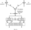
- FIG. 1b is a principle block diagram of the Alamouti code.
- a symbol transmitted on antenna 1 is denoted as s 1
- a symbol transmitted on antenna 2 is denoted as s 2 .
- a symbol transmitted on antenna 1 is ( ⁇ s 2 ⁇ )
- a symbol transmitted on antenna 2 is s 1 ⁇ .
- S space time block code matrix
- n 1 and n 2 represent received noise and signal interference.
- s ⁇ 1 ⁇ 1 2 + ⁇ 2 2 s 1 + h 1 ⁇ n 1 + h 2 n 2 ⁇
- s ⁇ 2 ⁇ 1 2 + ⁇ 2 2 s 2 ⁇ h 1 n 2 ⁇ + h 2 ⁇ n 1 .
- signals s 1 and s 2 can be estimated by using an ML detector.
- Table 1 S -S S* -S* ⁇ s 1 s 2 s 2 ⁇ s 1 ⁇ s 1 ⁇ s 2 ⁇ s 2 ⁇ ⁇ s 1 ⁇ ⁇ s 1 ⁇ s 2 ⁇ s 2 s 1 s 1 ⁇ ⁇ s 2 ⁇ ⁇ s 2 ⁇ s 1 s 1 ⁇ ⁇ s 2 ⁇ s 2 ⁇ s 1 ⁇ ⁇ s 1 ⁇ s 2 s 2 ⁇ s 1 ⁇ ⁇ s 1 ⁇ s 2 ⁇ s 2 ⁇ ⁇ s 1 ⁇ s 1 ⁇ s 2 ⁇ s 2 s 1 ⁇ s 1 ⁇ s 2 ⁇ ⁇ s 2 s 1 ⁇ s 1 ⁇ s 2 ⁇ ⁇ s 2 s 1 ⁇ s 1 ⁇ s 2 ⁇ ⁇ s 2 ⁇ s 1 s 1 s 2 s 2 ⁇ ⁇ s 1 ⁇
- New space time block code (New Space Time Block Code, NSTBC):
- backscatter backscatter
- some researchers put forward a concept of backscatter (Backscatter) diversity and design a corresponding space time block codeword. Based on this type of codeword, hardware implementation complexity is reduced, and a probability of error detection is reduced by optimizing a codebook of conventional Alamouti codes.
- a symbol transmitted on antenna 1 is denoted as s 1
- a symbol transmitted on antenna 2 is denoted as s 2 ⁇
- a symbol transmitted on antenna 1 is denoted as s 2
- a symbol transmitted on antenna 2 is denoted as ( ⁇ s 1 ⁇ ).
- S 2 belongs to the OSTBC codeword, and therefore can achieve a full diversity gain and full rate transmission. The following analyzes differences between this type of codeword and the conventional Alamouti code in backscatter communication.
- a coding table for transmitting different symbols simultaneously on two antennas by using a diversity encoding codeword S 2 is Table 4.
- Table 2 and Table 3 also provide coding tables for transmitting different symbols simultaneously on two antennas by using an Alamouti codeword and an extended Alamouti codeword.
- the extended Alamouti codeword is: s 1 s 2 s 2 ⁇ ⁇ s 1 ⁇ .
- antenna 1 requires only two coefficients
- both antenna 1 and antenna 2 require four coefficients
- DSTBC Differential space time block code
- the decoder uses a coherent detection decoding scheme. Therefore, the decoder requires accurate channel state information (Chanel State Information, CSI) from a transmit antenna to a receive antenna.
- CSI Channel State Information
- the decoder In high-speed movement scenarios or scenarios with fast-changing channel fading conditions, or scenarios in which it is difficult to transmit pilots due to power limitations in backscatter communication, it is difficult for the decoder to perform channel estimation accurately or costs of accurate channel estimation are high. In this case, the decoder cannot obtain accurate CSI information.
- the differential space time block code is a scheme in which neither the encoder nor the decoder needs to know CSI information, encoding and decoding are simple, and diversity gains can be obtained. The following uses two-antenna transmission and single-antenna reception as examples for description.
- Signals s 1 and s 2 transmitted at the two times do not carry information and are used only as reference signals.
- the encoder performs transmission in a differential encoding mode. Assuming that in a (2t - 1) th symbol period, symbols transmitted on a first antenna and a second antenna are s 2t-1 and s 2t respectively, in a 2t th symbol period, symbols transmitted on the first antenna and the second antenna are ⁇ s 2 t ⁇ and s 2 t ⁇ 1 ⁇ respectively. In a (2t+1) th symbol period, a group of 2m bits arrives at the encoder, and a corresponding coefficient vector (A( ), B( )) is generated.
- the transmitted symbols are repeatedly encoded.
- R 1 r 2 t + 1 r 2 t ⁇ 1 ⁇ + r 2 t + 2 ⁇ r 2 t
- N 1 s 2 t + 1 s 2 t + 2 ⁇ ⁇ 1 ⁇ 2 N 2 t ⁇ 1 * + N 2 t + 1 ⁇ * ⁇ 1 ⁇ 2 s 2 t ⁇ 1 * s 2 t * + N 2 t + 1 N 2 t ⁇ 1 * .
- R 1 ⁇ 1 2 + ⁇ 2 A D 2 t ⁇ 1 + N 1 .
- s 2 t + 1 s 2 t + 2 A D 2 t + 1 s 2 t ⁇ 1 s 2 t + B D 2 t + 1 ⁇ s 2 t * , s 2 t ⁇ 1 * .
- R 2 r 2 t + 1 r 2 t * ⁇ r 2 t + 2 * r 2 t ⁇ 1
- N 2 s 2 t + 1 s 2 t + 2 ⁇ ⁇ 1 ⁇ 2 N 2 t * + N 2 t + 1 ⁇ * ⁇ 1 ⁇ 2 ⁇ s 2 t , s 2 t ⁇ 1 + N 2 t + 1 N 2 t * .
- R 2 ⁇ 1 2 + ⁇ 2 2 B D 2 t ⁇ 1 + N 2 .
- R 1 R 2 ⁇ 1 2 + ⁇ 2 2 A D 2 t + 1 , B D 2 t + 1 + N 1 N 2 .
- a receiver selects a coefficient vector ( ⁇ ( ), B ⁇ ( )) with a shortest Euclidean distance for determining a signal vector ( ) as a decoding output:
- an embodiment of this application provides a decoding method.
- the method is performed by a decoder.
- the decoder may be a terminal device or a network-side device.
- the method includes the following steps.
- Step 201 A decoder determines an encoding coefficient vector based on a received signal and an NSTBC codebook.
- Step 202 The decoder decodes original encoded input symbols in a current symbol period based on the encoding coefficient vector, a DSTBC encoding mode, and the NSTBC codebook.
- a signal vector is constructed, and the encoding coefficient vector is calculated; and on the other hand, the original encoded input symbols in the current symbol period are calculated and restored based on the calculated encoding coefficient vector, the DSTBC encoding mode, and the NSTBC codebook. Based on this decoding mode, original symbols can be restored in absence of a pilot, and system overheads can be reduced.
- a quantity or types of load impedances on each antenna can be reduced, and a probability of error detection can be effectively reduced, while a diversity gain is ensured.
- the decoding method provided in this embodiment of this application is a new decoding method obtained by combining the DSTBC encoding mode and the NSTBC codebook and extracting advantages of the two.
- This new decoding method may also be referred to as a differential NSTBC decoding mode.
- the signal vector may also be referred to as a statistical signal vector.
- the original encoded input symbols refer to symbols that have been encoded by an encoder and that have not been subjected to channel gains and/or noise. Different from signals directly received by the decoder, the original encoded input symbols are symbols that need to be obtained by the decoder through decoding.
- a codebook structure of the NSTBC codebook meets: s 2 t + 1 s 2 t + 2 ⁇ s 2 t + 2 ⁇ s 2 t + 1 ⁇ , where s 2t+1 and s 2 t + 2 * are transmitted symbols that are on two transmit antennas and that are obtained by the encoder through encoding in the (2t+1) th symbol period (it should be noted that the transmitted symbols may also be referred to as constellation symbols, constellation points, or the like, and the name is not specifically limited in this embodiment of this application), s 2t+2 and ⁇ s 2 t + 1 * are transmitted symbols that are on two transmit antennas and that are obtained by the encoder through encoding in the (2t+2) th symbol period, the symbol s 2 t + 2 * is a conjugate of the symbol s 2t+2 , the symbol ⁇ s 2 t + 1 * is a negative conjugate of the symbol s 2t+1 , the (2t+1) th symbol
- a decoder determines an encoding coefficient vector based on a received signal and a new space time block code NSTBC codebook includes:
- the decoder determines an encoding coefficient vector of the decoder in the current symbol period based on the signal vector in the foregoing (2) includes:
- the decoder determines, based on a formula
- ( ) is the signal vector
- ( ⁇ ( ), B ⁇ ( )) is the encoding coefficient vector determined by the decoder in the (2t+1) th symbol period.
- the decoder selects the encoding coefficient vector ( ⁇ ( ), B ⁇ ( )) with a shortest Euclidean distance to the signal vector ( , ) as a decision output based on the foregoing formula, which is generally estimated by using a maximum likelihood algorithm.
- the decoder decodes original encoded input symbols in a current symbol period based on the encoding coefficient vector of the decoder in the current symbol period, a DSTBC encoding mode, and the NSTBC codebook includes:
- the method further includes:
- the decoder determines the original bits or the original symbols by directly querying the table.
- the original bits or the original symbols refer to initial data bits or initial symbols to be encoded at the encoder, and the initial reference symbols refer to reference symbols on the transmit antennas in an initial symbol period, that is, in a first symbol period.
- the decoder performs decoding processing in the foregoing manner, and finally the decoder obtains the initial data bits or the initial symbols.
- the method further includes:
- the decoder directly calculates the original bits or the original symbols.
- An advantage of this processing is that the decoder does not need to store the mapping table, but decodes the original encoded input symbols through real-time calculation.
- the method further includes:
- the decoder completes decoding processing in the first two symbol periods.
- the foregoing decoding processing manner in the (2t+1) th symbol period can be used in the third symbol period and subsequent symbol periods.
- that the decoder determines a signal vector based on the received signal and the NSTBC codebook includes:
- the signal vector ( , ) meets: and where ( ) is a linear combination vector of wanted signals, and ( ) is a noise interference vector, that is, the signal vector ( , ) includes two parts: the linear combination vector ( , ) of wanted signals, and the noise interference vector ( , ) .
- ( , ) meets:
- the foregoing describes the process in which the decoder decodes the original encoded input symbols in the current symbol period.
- the entire differential NSTBC decoding transmission may be completed by repeating the foregoing process.
- two transmit antennas and a single receive antenna are used as an example for description.
- (1) Calculate a statistical signal vector ( , ) based on received signals.
- a statistical signal component r 2t + 1 r 2t ⁇ 1 ⁇ + r 2t + 2 ⁇ r 2t ,
- the first statistical signal component can be obtained:
- a statistical signal component r 2 t + 1 r 2 t * ⁇ r 2 t + 2 * r 2 t ⁇ 1
- N 2 s 2 t + 1 s 2 t + 2 * ⁇ ⁇ 1 ⁇ 2 M 2 t * + N 2 t + 1 ⁇ * ⁇ 1 ⁇ 2 s 2 t * , ⁇ s 2 t ⁇ 1 + N 2 t + 1 M 2 t *
- a decoder After obtaining the statistical signal vector ( , ) of the received signals, a decoder selects an encoding coefficient vector ( ⁇ ( ), B ⁇ ( )) with a shortest Euclidean distance to the statistical signal vector ( , ) as a decision output:
- the decoder does not need to store a mapping table, but decodes an original input signal through real-time calculation.
- BPSK is used as an example to describe differential NSTBC decoding.
- a set of constellation points is ⁇ 1 2 1 2 , where 2 in the set of constellation points is to ensure normalization processing of transmit power, and a set of encoding coefficient vectors is .
- two input information bits at an input end of an encoder are c 1 and c 2
- the first bit c 1 is mapped to a symbol s 3
- the second bit c 2 is mapped to a symbol s 4
- the symbols s 3 and s 4 are both BPSK constellation points.
- a D 3 s 3 s 1 ⁇ + s 4 ⁇ s 2
- B D 3 s 3 s 2 ⁇ ⁇ s 4 ⁇ s 1 .
- mapping table between the input bits and (A( ), B( )) may be obtained:
- mapping table is applicable to a coefficient vector ( ⁇ , B ⁇ ) in different symbol periods after initial reference symbols are determined, after a coefficient vector ( ⁇ ( ), B ⁇ ( )) is obtained through calculation, the input symbols or input bits (c 1 , c 2 ) can be demapped and obtained by querying the mapping table.
- An advantage of this implementation is that the original input symbols are restored by directly querying the mapping table without calculation, so that implementation complexity and a decoding delay are both lower.
- the decoding method provided in this embodiment of this application may be performed by a decoding apparatus.
- a decoding apparatus provided in an embodiment of this application is described by assuming that the decoding apparatus performs the decoding method in this embodiment of this application.
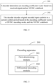
- an embodiment of this application provides a decoding apparatus 300, including:
- a signal vector is constructed, and the encoding coefficient vector is calculated; and on the other hand, the original encoded input symbols in the current symbol period are calculated and restored based on the calculated encoding coefficient vector, the DSTBC encoding mode, and the NSTBC codebook. Based on this decoding mode, original symbols can be restored in absence of a pilot, and system overheads can be reduced.
- a quantity or types of load impedances on each antenna can be reduced, and a probability of error detection can be effectively reduced, while a diversity gain is ensured.
- a codebook structure of the NSTBC codebook meets: s 2 t + 1 s 2 t + 2 ⁇ s 2 t + 2 ⁇ s 2 t + 1 ⁇ , where s 2t+1 and s 2 t + 2 * are original encoded input symbols decoded by the decoder in a (2t+1) th symbol period, s 2t+2 and ⁇ s 2t + 1 * are original encoded input symbols decoded by the decoder in a (2t+2) th symbol period, the symbol s 2t + 2 * is a conjugate of the symbol s 2t+2 , the symbol ⁇ s 2t + 1 * is a negative conjugate of the symbol s 2t+1 , the (2t+1) th symbol period is the current symbol period, and the (2t+2) th symbol period is a symbol period next to the current symbol period.
- the first determining module is specifically configured to:
- the first determining module is specifically configured to:
- the differential decoding module is specifically configured to:
- the apparatus further includes:
- the apparatus further includes:
- the apparatus further includes:
- the first determining module is specifically configured to:
- the signal vector ( ) meets: and where ( ) is a linear combination vector of wanted signals, and ( ) is a noise interference vector.
- ( ) meets: and
- the decoding apparatus in this embodiment of this application may be an electronic device, for example, an electronic device with an operating system, or may be a component in an electronic device, for example, an integrated circuit or a chip.
- the electronic device may be a terminal, or may be other devices than a terminal.
- the terminal may include but is not limited to the foregoing illustrated type of the terminal 11.
- the other devices may be a server, a network attached storage (Network Attached Storage, NAS), and the like. This is not specifically limited in this embodiment of this application.
- the decoding apparatus provided in this embodiment of this application can implement each process implemented by the method embodiment in FIG. 2 , with the same technical effect achieved. To avoid repetition, details are not described herein again.
- an embodiment of this application further provides a communication device 400, including a processor 401 and a memory 402.
- the memory 402 stores a program or instructions capable of running on the processor 401.
- each step of the foregoing embodiment of the decoding apparatus method is implemented, with the same technical effect achieved.
- the communication device 400 is a network-side device, and the program or instructions are executed by the processor 401, each step of the foregoing embodiment of the decoding apparatus method is implemented, with the same technical effect achieved. To avoid repetition, details are not described herein again.
- An embodiment of this application further provides a decoder, including a processor and a communication interface.
- the processor is configured to: determine, by the decoder, an encoding coefficient vector based on a received signal and an NSTBC codebook; and decode, by the decoder, original encoded input symbols in a current symbol period based on the encoding coefficient vector, a DSTBC encoding mode, and the NSTBC codebook.
- FIG. 5 is a schematic diagram of a hardware structure of a terminal for implementing an embodiment of this application.
- the terminal 500 includes but is not limited to at least some components such as a radio frequency unit 501, a network module 502, an audio output unit 503, an input unit 504, a sensor 505, a display unit 506, a user input unit 507, an interface unit 508, a memory 509, and a processor 510.
- the terminal 500 may further include a power supply (for example, a battery) supplying power to all components.
- the power supply may be logically connected to the processor 510 through a power management system. In this way, functions such as charge management, discharge management, and power consumption management are implemented by using the power management system.
- the terminal structure shown in FIG. 5 does not constitute a limitation on the terminal.
- the terminal may include more or fewer components than those shown in the figure, or some components are combined, or component arrangements are different. Details are not described herein again.
- the input unit 504 may include a graphics processing unit (Graphics Processing Unit, GPU) 5041 and a microphone 5042.
- the graphics processing unit 5041 processes image data of a still picture or video obtained by an image capture apparatus (such as a camera) in a video capture mode or an image capture mode.
- the display unit 506 may include a display panel 5061, and the display panel 5061 may be configured in a form of a liquid crystal display, an organic light-emitting diode, or the like.
- the user input unit 507 includes at least one of a touch panel 5071 and other input devices 5072.
- the touch panel 5071 is also referred to as a touchscreen.
- the touch panel 5071 may include two parts: a touch detection apparatus and a touch controller.
- the other input devices 5072 may include but are not limited to a physical keyboard, a function button (such as a volume control button or a power button), a trackball, a mouse, and a joystick. Details are not described herein again.
- the radio frequency unit 501 may transmit the downlink data to the processor 510 for processing.
- the radio frequency unit 501 may send uplink data to the network-side device.
- the radio frequency unit 501 includes but is not limited to an antenna, an amplifier, a transceiver, a coupler, a low noise amplifier, a duplexer, and the like.
- the memory 509 may be configured to store software programs or instructions and various data.
- the memory 509 may primarily include a first storage area for storing programs or instructions and a second storage area for storing data.
- the first storage area may store an operating system, an application program or instructions required by at least one function (such as an audio play function and an image play function), and the like.
- the memory 509 may include a volatile memory or a non-volatile memory, or the memory 509 may include both a volatile memory and a non-volatile memory.
- the non-volatile memory may be a read-only memory (Read-Only Memory, ROM), a programmable read-only memory (Programmable ROM, PROM), an erasable programmable read-only memory (Erasable PROM, EPROM), an electrically erasable programmable read-only memory (Electrically EPROM, EEPROM), or a flash memory.
- ROM Read-Only Memory
- PROM programmable read-only memory
- Erasable PROM Erasable PROM
- EPROM electrically erasable programmable read-only memory
- EEPROM electrically erasable programmable read-only memory
- the volatile memory may be a random access memory (Random Access Memory, RAM), a static random access memory (Static RAM, SRAM), a dynamic random access memory (Dynamic RAM, DRAM), a synchronous dynamic random access memory (Synchronous DRAM, SDRAM), a double data rate synchronous dynamic random access memory (Double Data rate SDRAM, DDR SDRAM), an enhanced synchronous dynamic random access memory (Enhanced SDRAM, ESDRAM), a synchlink dynamic random access memory (Synch Link DRAM, SLDRAM), and a direct rambus random access memory (Direct Rambus RAM, DRRAM).
- RAM Random Access Memory
- SRAM static random access memory
- DRAM dynamic random access memory
- DRAM synchronous dynamic random access memory
- SDRAM double data rate synchronous dynamic random access memory
- Enhanced SDRAM, ESDRAM enhanced synchronous dynamic random access memory
- Synch Link DRAM Synchlink dynamic random access memory
- SLDRAM direct rambus random access memory
- Direct Rambus RAM Direct Rambus RAM,
- the processor 510 may include one or more processing units.
- the processor 510 integrates an application processor and a modem processor.
- the application processor mainly processes operations related to the operating system, a user interface, an application program, and the like.
- the modem processor mainly processes a wireless communication signal.
- the modem processor is a baseband processor. It may be understood that the modem processor may alternatively not be integrated in the processor 510.
- the processor 510 is configured to determine, by a decoder, an encoding coefficient vector based on a received signal and an NSTBC codebook.
- the processor 510 is configured to decode, by the decoder, original encoded input symbols in a current symbol period based on the encoding coefficient vector, a DSTBC encoding mode, and the NSTBC codebook.
- a signal vector is constructed, and the encoding coefficient vector is calculated; and on the other hand, the original encoded input symbols in the current symbol period are calculated and restored based on the calculated encoding coefficient vector, the DSTBC encoding mode, and the NSTBC codebook. Based on this decoding mode, original symbols can be restored in absence of a pilot, and system overheads can be reduced.
- a quantity or types of load impedances on each antenna can be reduced, and a probability of error detection can be effectively reduced, while a diversity gain is ensured.
- a codebook structure of the NSTBC codebook meets: s 2 t + 1 s 2 t + 2 * s 2 t + 2 ⁇ s 2 t + 1 * , where s 2t+1 and s 2 t + 2 ⁇ are original encoded input symbols decoded by the decoder in a (2t+1) th symbol period, s 2t+2 and ⁇ s 2 t + 1 * are original encoded input symbols decoded by the decoder in a (2t+2) th symbol period, the symbol s 2 t + 2 * is a conjugate of the symbol s 2t+2 , the symbol ⁇ s 2 t + 1 * is a negative conjugate of the symbol s 2t+1 , the (2t+1) th symbol period is the current symbol period, and the (2t+2) th symbol period is a symbol period next to the current symbol period.
- the processor 510 is specifically configured to:
- the processor 510 is specifically configured to:
- the processor 510 is specifically configured to:
- the processor 510 is configured to determine, by the decoder, original bits or original symbols based on a preset mapping table between the original bits or the original symbols and ( ⁇ ( ), B ⁇ ( )), where the preset mapping table between the original bits or the original symbols and ( ⁇ ( ), B ⁇ ( )) includes a mapping relationship between the original bits or the original symbols and the encoding coefficient vector ( ⁇ ( ), B ⁇ ( )) after initial reference symbols are determined.
- the processor 510 is configured to determine, by the decoder, original symbols (s 2t+1 , s 2t+2 ) based on the decoded original encoded input symbols s 2 t + 1 s 2 t + 2 * ; and determine, by the decoder, original bits based on (s 2t+1 , s 2t+2 ).
- the processor 510 is configured to determine, by the decoder, that original encoded input symbols in a first symbol period are s 1 s 2 * and that original encoded input symbols in a second symbol period are s 2 , ⁇ s 1 * , where
- the processor 510 is specifically configured to:
- the signal vector ( ) meets: , and where ( ) is a linear combination vector of wanted signals, and ( ) is a noise interference vector.
- ( ) meets:
- the network-side device 600 includes an antenna 61, a radio frequency apparatus 62, a baseband apparatus 63, a processor 64, and a memory 65.
- the antenna 61 is connected to the radio frequency apparatus 62.
- the radio frequency apparatus 62 receives information by using the antenna 61, and sends the received information to the baseband apparatus 63 for processing.
- the baseband apparatus 63 processes to-be-sent information, and sends the information to the radio frequency apparatus 62; and the radio frequency apparatus 62 processes the received information and then sends the information out by using the antenna 61.
- the method in the foregoing method embodiment may be implemented in the baseband apparatus 63.
- the baseband apparatus 63 includes a baseband processor.
- the baseband apparatus 63 may include, for example, at least one baseband unit, where a plurality of chips are disposed on the baseband unit. As shown in FIG. 6 , one of the chips is, for example, the baseband processor, connected to the memory 65 by using a bus interface, to invoke a program in the memory 65 to perform the operation of the network-side device shown in the foregoing method embodiment.
- the network-side device may further include a network interface 66, where the interface is, for example, a common public radio interface (common public radio interface, CPRI).
- a common public radio interface common public radio interface, CPRI
- the network-side device 600 in this embodiment of the present invention further includes a program or instructions stored in the memory 65 and capable of running on the processor 64.
- the processor 64 invokes the program or instructions in the memory 65, the method performed by each module shown in FIG. 3 is performed, with the same technical effect achieved. To avoid repetition, details are not described herein again.
- An embodiment of this application further provides a readable storage medium.
- the readable storage medium stores a program or instructions.
- the program or instructions are executed by a processor, each process of the foregoing embodiment of the decoding method is implemented, with the same technical effect achieved. To avoid repetition, details are not described herein again.
- the processor is a processor in the terminal in the foregoing embodiment.
- the readable storage medium includes a computer-readable storage medium, such as a computer read-only memory ROM, a random access memory RAM, a magnetic disk, or an optical disc.
- an embodiment of this application provides a chip.
- the chip includes a processor and a communication interface.
- the communication interface is coupled to the processor.
- the processor is configured to run a program or instructions to implement each process of the foregoing embodiment of the decoding method, with the same technical effect achieved. To avoid repetition, details are not described herein again.
- the chip provided in this embodiment of this application may also be referred to as a system-level chip, a system chip, a chip system, a system-on-chip, or the like.
- an embodiment of this application provides a computer program product.
- the computer program product is stored in a storage medium.
- the computer program product is executed by at least one processor to implement each process of the foregoing embodiment of the decoding method, with the same technical effect achieved. To avoid repetition, details are not described herein again.
- the computer software product is stored in a storage medium (such as a ROM/RAM, a magnetic disk, or an optical disc), and includes several instructions for instructing a terminal (which may be a mobile phone, a computer, a server, an air conditioner, a network device, or the like) to perform the methods described in the embodiments of this application.
- a storage medium such as a ROM/RAM, a magnetic disk, or an optical disc
- a terminal which may be a mobile phone, a computer, a server, an air conditioner, a network device, or the like
Landscapes
- Engineering & Computer Science (AREA)
- Signal Processing (AREA)
- Computer Networks & Wireless Communication (AREA)
- Multimedia (AREA)
- Radio Transmission System (AREA)
- Compression, Expansion, Code Conversion, And Decoders (AREA)
- Compression Or Coding Systems Of Tv Signals (AREA)
Applications Claiming Priority (2)
| Application Number | Priority Date | Filing Date | Title |
|---|---|---|---|
| CN202111658371.5A CN116418998B (zh) | 2021-12-30 | 2021-12-30 | 解码方法、设备及可读存储介质 |
| PCT/CN2022/141969 WO2023125424A1 (zh) | 2021-12-30 | 2022-12-26 | 解码方法、设备及可读存储介质 |
Publications (2)
| Publication Number | Publication Date |
|---|---|
| EP4459916A1 true EP4459916A1 (de) | 2024-11-06 |
| EP4459916A4 EP4459916A4 (de) | 2025-04-16 |
Family
ID=86997826
Family Applications (1)
| Application Number | Title | Priority Date | Filing Date |
|---|---|---|---|
| EP22914678.2A Pending EP4459916A4 (de) | 2021-12-30 | 2022-12-26 | Decodierungsverfahren und -vorrichtung und lesbares speichermedium |
Country Status (4)
| Country | Link |
|---|---|
| US (1) | US12494826B2 (de) |
| EP (1) | EP4459916A4 (de) |
| CN (1) | CN116418998B (de) |
| WO (1) | WO2023125424A1 (de) |
Family Cites Families (12)
| Publication number | Priority date | Publication date | Assignee | Title |
|---|---|---|---|---|
| US7773699B2 (en) * | 2001-10-17 | 2010-08-10 | Nortel Networks Limited | Method and apparatus for channel quality measurements |
| DE102005040067B4 (de) * | 2005-08-24 | 2007-08-30 | Siemens Ag | Verfahren Sendevorrichtung und Empfangsvorrichtung zum Kodieren von Daten mit einem differenziellen Raum-Zeit-Blockkode |
| US8027407B2 (en) * | 2006-11-06 | 2011-09-27 | Ntt Docomo, Inc. | Method and apparatus for asynchronous space-time coded transmission from multiple base stations over wireless radio networks |
| CN101267234B (zh) * | 2007-03-13 | 2013-03-13 | 上海贝尔阿尔卡特股份有限公司 | 空时分组码编解码的方法及装置 |
| CN103326825B (zh) * | 2013-06-26 | 2016-06-01 | 江南大学 | 一种准正交空时分组码低复杂度译码方法 |
| US9716568B2 (en) * | 2013-09-26 | 2017-07-25 | Hitachi Kokusai Electric Inc. | Wireless communication system and transmitter |
| EP3107235B1 (de) * | 2015-06-16 | 2019-08-14 | Mitsubishi Electric R&D Centre Europe B.V. | Verfahren zur berechnung von wahrscheinlichkeiten in einem verfahren zur rekonstruktion von decodierten informationsworten |
| EP3605907A4 (de) * | 2017-05-10 | 2020-04-22 | Mitsubishi Electric Corporation | Übertragungsvorrichtung, basisstationseinrichtung und drahtloskommunikationssystem |
| CN108234082B (zh) * | 2017-11-29 | 2020-08-04 | 重庆邮电大学 | 一种基于空间调制的满分集空时编码方法 |
| KR102090620B1 (ko) * | 2018-11-27 | 2020-03-18 | 성균관대학교 산학협력단 | 무선 전력 이종통신망에서 후방산란 기반 협력통신 시스템 및 그 방법 |
| CN116506084B (zh) * | 2022-01-18 | 2025-11-14 | 维沃移动通信有限公司 | 编码方法、设备及可读存储介质 |
| CN116527089A (zh) * | 2022-01-20 | 2023-08-01 | 维沃移动通信有限公司 | 编码方法、设备及可读存储介质 |
-
2021
- 2021-12-30 CN CN202111658371.5A patent/CN116418998B/zh active Active
-
2022
- 2022-12-26 EP EP22914678.2A patent/EP4459916A4/de active Pending
- 2022-12-26 WO PCT/CN2022/141969 patent/WO2023125424A1/zh not_active Ceased
-
2024
- 2024-06-14 US US18/744,230 patent/US12494826B2/en active Active
Also Published As
| Publication number | Publication date |
|---|---|
| US20240340047A1 (en) | 2024-10-10 |
| EP4459916A4 (de) | 2025-04-16 |
| CN116418998B (zh) | 2025-09-23 |
| US12494826B2 (en) | 2025-12-09 |
| WO2023125424A1 (zh) | 2023-07-06 |
| CN116418998A (zh) | 2023-07-11 |
Similar Documents
| Publication | Publication Date | Title |
|---|---|---|
| US20240388382A1 (en) | Encoding method, device, and readable storage medium | |
| US20170085358A1 (en) | System and Method for Multiple-Input and Multiple-Output (MIMO) Full-Duplex Precoding Algorithms | |
| EP4576633A1 (de) | Datenübertragungsverfahren und kommunikationsvorrichtung | |
| CN117336121A (zh) | 信道估计方法、装置、通信设备、系统及存储介质 | |
| US20240340104A1 (en) | Encoding method and apparatus, and readable storage medium | |
| US20240372650A1 (en) | Coding method and apparatus and readable storage medium | |
| US12562783B2 (en) | Diversity transmission method, terminal, and network-side device | |
| EP4459916A1 (de) | Decodierungsverfahren und -vorrichtung und lesbares speichermedium | |
| US12476730B2 (en) | Method and apparatus for performing signal compensation based on frequency resource allocation | |
| EP4507223A1 (de) | Kommunikationsverfahren, -vorrichtung und -system | |
| US11483039B2 (en) | Method and apparatus for detecting signal with quantum computing in MIMO system | |
| WO2023138459A1 (zh) | 解码方法、设备及可读存储介质 | |
| US12119931B2 (en) | Zigzag decoding of upstream-processed signals from independent receiver subarrays | |
| US20250365186A1 (en) | Information processing method and apparatus, terminal, and network side device | |
| US20260101343A1 (en) | Method and apparatus of uplink transmission | |
| US12597982B2 (en) | Determining error vector magnitude for a single layer transmission using a multiple-input multiple-output receiver | |
| US20260128783A1 (en) | Control methods for receiver antenna selection and interference cancelation and apparatus thereof | |
| WO2025007845A1 (zh) | 编码方法、解码方法、装置及通信设备 | |
| CN120856526A (zh) | 无线通信系统中的节点及其执行的方法 | |
| CN108418654A (zh) | 一种信号检测方法及装置 |
Legal Events
| Date | Code | Title | Description |
|---|---|---|---|
| STAA | Information on the status of an ep patent application or granted ep patent |
Free format text: STATUS: THE INTERNATIONAL PUBLICATION HAS BEEN MADE |
|
| PUAI | Public reference made under article 153(3) epc to a published international application that has entered the european phase |
Free format text: ORIGINAL CODE: 0009012 |
|
| STAA | Information on the status of an ep patent application or granted ep patent |
Free format text: STATUS: REQUEST FOR EXAMINATION WAS MADE |
|
| 17P | Request for examination filed |
Effective date: 20240610 |
|
| AK | Designated contracting states |
Kind code of ref document: A1 Designated state(s): AL AT BE BG CH CY CZ DE DK EE ES FI FR GB GR HR HU IE IS IT LI LT LU LV MC ME MK MT NL NO PL PT RO RS SE SI SK SM TR |
|
| REG | Reference to a national code |
Ref country code: DE Ref legal event code: R079 Free format text: PREVIOUS MAIN CLASS: H04L0005000000 Ipc: H04L0001000000 |
|
| DAV | Request for validation of the european patent (deleted) | ||
| DAX | Request for extension of the european patent (deleted) | ||
| A4 | Supplementary search report drawn up and despatched |
Effective date: 20250317 |
|
| RIC1 | Information provided on ipc code assigned before grant |
Ipc: H04L 5/00 20060101ALI20250312BHEP Ipc: H04B 7/06 20060101ALI20250312BHEP Ipc: H04B 7/04 20170101ALI20250312BHEP Ipc: H04L 1/00 20060101AFI20250312BHEP |