EP4459820A1 - System und verfahren für eine elektrolyseanlage, die mit einer erneuerbaren energiequelle und einem stromnetz verbunden ist - Google Patents
System und verfahren für eine elektrolyseanlage, die mit einer erneuerbaren energiequelle und einem stromnetz verbunden ist Download PDFInfo
- Publication number
- EP4459820A1 EP4459820A1 EP23171279.5A EP23171279A EP4459820A1 EP 4459820 A1 EP4459820 A1 EP 4459820A1 EP 23171279 A EP23171279 A EP 23171279A EP 4459820 A1 EP4459820 A1 EP 4459820A1
- Authority
- EP
- European Patent Office
- Prior art keywords
- power
- power supply
- renewable energy
- electrolyzers
- energy electrical
- Prior art date
- Legal status (The legal status is an assumption and is not a legal conclusion. Google has not performed a legal analysis and makes no representation as to the accuracy of the status listed.)
- Withdrawn
Links
Images


Classifications
-
- H—ELECTRICITY
- H02—GENERATION; CONVERSION OR DISTRIBUTION OF ELECTRIC POWER
- H02J—ELECTRIC POWER NETWORKS; CIRCUIT ARRANGEMENTS OR SYSTEMS FOR SUPPLYING OR DISTRIBUTING ELECTRIC POWER; SYSTEMS FOR STORING ELECTRIC ENERGY
- H02J1/00—Circuit arrangements for DC mains or DC distribution networks
- H02J1/10—Parallel operation of DC sources
-
- C—CHEMISTRY; METALLURGY
- C25—ELECTROLYTIC OR ELECTROPHORETIC PROCESSES; APPARATUS THEREFOR
- C25B—ELECTROLYTIC OR ELECTROPHORETIC PROCESSES FOR THE PRODUCTION OF COMPOUNDS OR NON-METALS; APPARATUS THEREFOR
- C25B1/00—Electrolytic production of inorganic compounds or non-metals
- C25B1/01—Products
- C25B1/02—Hydrogen or oxygen
- C25B1/04—Hydrogen or oxygen by electrolysis of water
-
- C—CHEMISTRY; METALLURGY
- C25—ELECTROLYTIC OR ELECTROPHORETIC PROCESSES; APPARATUS THEREFOR
- C25B—ELECTROLYTIC OR ELECTROPHORETIC PROCESSES FOR THE PRODUCTION OF COMPOUNDS OR NON-METALS; APPARATUS THEREFOR
- C25B15/00—Operating or servicing cells
-
- H—ELECTRICITY
- H02—GENERATION; CONVERSION OR DISTRIBUTION OF ELECTRIC POWER
- H02J—ELECTRIC POWER NETWORKS; CIRCUIT ARRANGEMENTS OR SYSTEMS FOR SUPPLYING OR DISTRIBUTING ELECTRIC POWER; SYSTEMS FOR STORING ELECTRIC ENERGY
- H02J9/00—Circuit arrangements for emergency or stand-by power supply, e.g. for emergency lighting
- H02J9/04—Circuit arrangements for emergency or stand-by power supply, e.g. for emergency lighting in which the distribution system is disconnected from the normal source and connected to a standby source
- H02J9/06—Circuit arrangements for emergency or stand-by power supply, e.g. for emergency lighting in which the distribution system is disconnected from the normal source and connected to a standby source with automatic change-over, e.g. UPS systems
- H02J9/061—Circuit arrangements for emergency or stand-by power supply, e.g. for emergency lighting in which the distribution system is disconnected from the normal source and connected to a standby source with automatic change-over, e.g. UPS systems for DC powered loads
-
- C—CHEMISTRY; METALLURGY
- C25—ELECTROLYTIC OR ELECTROPHORETIC PROCESSES; APPARATUS THEREFOR
- C25B—ELECTROLYTIC OR ELECTROPHORETIC PROCESSES FOR THE PRODUCTION OF COMPOUNDS OR NON-METALS; APPARATUS THEREFOR
- C25B15/00—Operating or servicing cells
- C25B15/02—Process control or regulation
-
- H—ELECTRICITY
- H02—GENERATION; CONVERSION OR DISTRIBUTION OF ELECTRIC POWER
- H02J—ELECTRIC POWER NETWORKS; CIRCUIT ARRANGEMENTS OR SYSTEMS FOR SUPPLYING OR DISTRIBUTING ELECTRIC POWER; SYSTEMS FOR STORING ELECTRIC ENERGY
- H02J2101/00—Supply or distribution of decentralised, dispersed or local electric power generation
- H02J2101/20—Dispersed power generation using renewable energy sources
-
- Y—GENERAL TAGGING OF NEW TECHNOLOGICAL DEVELOPMENTS; GENERAL TAGGING OF CROSS-SECTIONAL TECHNOLOGIES SPANNING OVER SEVERAL SECTIONS OF THE IPC; TECHNICAL SUBJECTS COVERED BY FORMER USPC CROSS-REFERENCE ART COLLECTIONS [XRACs] AND DIGESTS
- Y02—TECHNOLOGIES OR APPLICATIONS FOR MITIGATION OR ADAPTATION AGAINST CLIMATE CHANGE
- Y02E—REDUCTION OF GREENHOUSE GAS [GHG] EMISSIONS, RELATED TO ENERGY GENERATION, TRANSMISSION OR DISTRIBUTION
- Y02E60/00—Enabling technologies; Technologies with a potential or indirect contribution to GHG emissions mitigation
- Y02E60/30—Hydrogen technology
- Y02E60/36—Hydrogen production from non-carbon containing sources, e.g. by water electrolysis
-
- Y—GENERAL TAGGING OF NEW TECHNOLOGICAL DEVELOPMENTS; GENERAL TAGGING OF CROSS-SECTIONAL TECHNOLOGIES SPANNING OVER SEVERAL SECTIONS OF THE IPC; TECHNICAL SUBJECTS COVERED BY FORMER USPC CROSS-REFERENCE ART COLLECTIONS [XRACs] AND DIGESTS
- Y02—TECHNOLOGIES OR APPLICATIONS FOR MITIGATION OR ADAPTATION AGAINST CLIMATE CHANGE
- Y02P—CLIMATE CHANGE MITIGATION TECHNOLOGIES IN THE PRODUCTION OR PROCESSING OF GOODS
- Y02P20/00—Technologies relating to chemical industry
- Y02P20/10—Process efficiency
- Y02P20/133—Renewable energy sources, e.g. sunlight
Definitions
- Disclosed embodiments relate generally to the field of renewable energy, and, more particularly, to system and method for an electrolysis plant interconnected to a renewable energy power source and a power grid.
- Hydrogen is a clean fuel that, for example, when consumed in a fuel cell, can be used to cleanly and efficiently produce electricity. At least such qualities make hydrogen an attractive fuel option for various applications, such as electric power generation, transportation, etc.
- the production of hydrogen can be realized through various production techniques, each involving a primary source of energy.
- green hydrogen is hydrogen produced by splitting water molecules by electrolysis using renewable energy sources, such as wind turbines, photovoltaic systems, etc., rather than using, for example, natural gas, which can result in substantial amounts of CO2 emissions. Because of its positive impact to our planet's ecosystem, it is expected that the demand of green hydrogen will increase and in turn green hydrogen will command relatively higher prices in energy markets compared to, for example, hydrogen produced from non-renewable sources.
- a system in one aspect, includes a renewable energy electrical power source and an electrolysis plant including a plurality of electrolyzers electrically coupled to the renewable energy electrical power source to energize respective ones of the plurality of electrolyzers in respective operating conditions.
- the system further includes a control system of the electrolysis plant connected in parallel circuit to the renewable energy electrical power source and to a power grid. Upon detection of an occurrence of power outage or otherwise insufficient power supply by the renewable energy electrical power source, the control system is energized by the power grid.
- the control system is configured to bring the respective ones of the plurality of electrolyzers to respective standby conditions.
- the plurality of electrolyzers is electrically coupled to the power grid to energize the respective ones of the plurality of electrolyzers in the respective standby conditions.
- a method allows electrically coupling an electrolysis plant including a plurality of electrolyzers to a renewable energy electrical power source to energize respective ones of the plurality of electrolyzers in respective operating conditions.
- a control system of the electrolysis plant is connected in parallel circuit to the renewable energy electrical power source and to a power grid.
- the method allows detecting occurrence of a power outage or otherwise insufficient power supply by the renewable energy electrical power source.
- Upon detecting the occurrence of the power outage or the otherwise insufficient power supply by the renewable energy electrical power source energizing with the power grid the control system and controlling, by way of the control system, the respective ones of the plurality of electrolyzers to be brought to respective standby conditions.
- the plurality of electrolyzers is electrically coupled to the power grid to energize the respective ones of the plurality of electrolyzers in the respective standby conditions.
- the present inventors have recognized the importance of providing cost-effective and reliable solutions, such as may be used without limitation for applications involving hydrogen production, where renewable power sources may be arranged to form a renewable power plant and electrolyzers may be arranged to form an electrolysis plant.
- the electrolysis plant is normally powered for hydrogen production by the renewable power plant.
- connectivity to a power grid and/or to a back-up power supply are available to ensure the electrolysis plant can be brough to a safe condition, such as when there is a power outage or otherwise there is insufficient power supply by the renewable power plant.
- auxiliary power is supplied by the power grid.
- the auxiliary power is supplied by the power grid, the backup power supply or both.
- the present inventors disclose embodiments of system and method designed to provide reliable and cost-effective solutions, such as may involve providing auxiliary power from an alternative power source in a way to at least ensure safe transitioning of systems in the electrolysis plant from respective operating conditions to respective standby conditions, or to respective idle conditions, for example.
- the input power to any given electrolyzer in an operating condition (or state) can range from a minimum partial operation (typically about 10% of the electrolyzer's rated power) to full load operation. In this state, the electrolyzer produces hydrogen with a near-constant efficiency value.
- the electrolyzers transition to respective standby conditions there is no hydrogen production, but some moderate level of electricity consumption is involved to maintain, for example, a specific temperature and pressure within the electrolyzers.
- the electrolyzers are turned off (e.g., shutdown condition). That is, the electrolyzers would be depressurized and cold.
- phrases "associated with” and “associated therewith,” as well as derivatives thereof, may mean to include, be included within, interconnect with, contain, be contained within, connect to or with, couple to or with, be communicable with, cooperate with, interleave, juxtapose, be proximate to, be bound to or with, have, have a property of, or the like.
- any features, methods, steps, components, etc. described with regard to one embodiment are equally applicable to other embodiments absent a specific statement to the contrary.
- first, second, third and so forth may be used herein to refer to various elements, information, functions, or acts, these elements, information, functions, or acts should not be limited by these terms. Rather these numeral adjectives are used to distinguish different elements, information, functions or acts from each other. For example, a first element, information, function, or act could be termed a second element, information, function, or act, and, similarly, a second element, information, function, or act could be termed a first element, information, function, or act, without departing from the scope of the present disclosure.
- adjacent to may mean that an element is relatively near to but not in contact with a further element or that the element is in contact with the further portion, unless the context clearly indicates otherwise.
- phrase “based on” is intended to mean “based, at least in part, on” unless explicitly stated otherwise. Terms “about” or “substantially” or like terms are intended to cover variations in a value that are within normal industry manufacturing tolerances for that dimension. If no industry standard is available, a variation of twenty percent would fall within the meaning of these terms unless otherwise stated.
- computer/processor executable instructions may correspond to and/or may be generated from source code, byte code, runtime code, machine code, assembly, Java, JavaScript, Python, Rust, Swift, Go, C, C#, C++ or any other form of code that can be programmed/configured to cause at least one processor to carry out the acts and features described herein. Still further, results of the described/claimed processes or functions may be stored in a computer-readable medium, displayed on a display device, and/or the like.
- processors described herein may correspond to one or more (or a combination) of a microprocessor, CPU, or any other integrated circuit (IC) or other type of circuit that is capable of processing data in a data processing system.
- processors that is described or claimed as being configured to carry out a particular described/claimed process or function may correspond to a CPU that executes computer/processor executable instructions stored in a memory in the form of software to carry out such a described/claimed process or function.
- processors may correspond to an IC that is hardwired with processing circuitry (e.g., an FPGA or ASIC IC) to carry out such a described/claimed process or function.
- processing circuitry e.g., an FPGA or ASIC IC
- reference to a processor may include multiple physical processors or cores that are configured to carry out the functions described herein.
- a data processing system and/or a processor may correspond to a controller that is operably configured to control at least one operation including a programable logic controller (PLC).
- PLC programable logic controller
- processor or processor module that is described or claimed as being configured to carry out a particular described/claimed process or function may correspond to the combination of the processor with the executable instructions (e.g., software/firmware applications) loaded/installed into the described memory (volatile and/or non-volatile), which are currently being executed and/or are available to be executed by the processor to cause the processor to carry out the described/claimed process or function.
- executable instructions e.g., software/firmware applications
- a processor that is powered off or is executing other software, but has the described software loaded/stored in a storage device in operative connection therewith (such as in a flash memory, SSD, or hard drive) in a manner that is available to be executed by the processor (when started by a user, hardware and/or other software), may also correspond to the described/claimed processor that is operably configured to carry out the particular processes and functions described/claimed herein.
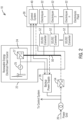
- FIG. 1 is a block diagram representation showing one non-limiting example of a disclosed system 10 connected to a power grid 20, which can be, but need not be, the power grid of a region or of a nation.
- power grid 20 can be a weak power grid compared to the overall power requirements to run the electrolysis plant.
- a weak power grid in this context is a grid that lacks sufficient power, short-circuit power or otherwise is considered insufficient in any other regard to appropriately energize the electrolyzers 32 into their respective operating conditions but has sufficient power to, for example, appropriately energize the electrolyzers 32 into respective standby conditions.
- System 10 includes a renewable energy electrical power source 22 that in one embodiment may be a wind turbine system 24.
- renewable energy electrical power source 22 may be a solar photovoltaic system 28, as shown in FIG. 3 . It is contemplated that in certain applications, renewable energy electrical power source 22 could be a hybrid renewable energy electrical power source, such as a combination of a wind turbine system, a solar photovoltaic system or any other non-fossil-fuel based power system.
- System 10 further includes an electrolysis plant 30 that includes a plurality of electrolyzers 32 electrically coupled to renewable energy electrical power source 22 to energize respective ones of the plurality of electrolyzers 32 to respective operating conditions or states.
- a control system 40 of electrolysis plant 30 is connected in parallel circuit to renewable energy electrical power source 22 and to power grid 20. In the event a power outage or otherwise insufficient power supply is detected in the renewable energy electrical power source 22, control system 40 is energized by the power grid. Control system 40 is configured to bring the respective ones of the plurality of electrolyzers 32 to respective standby conditions. In one example embodiment, the plurality of electrolyzers 32 is electrically coupled to the power grid 20 to energize the respective ones of the plurality of electrolyzers 32 in the respective standby conditions.
- the dashed lines in FIG.s 1 through 3 schematically represent non-limiting examples of certain electrical connections that may be optionally implemented depending on the specific needs of a given implementation.
- FIG. 2 is a block diagram representation showing another non-limiting example of a disclosed system 10.
- a backup power supply 26 such as a battery backup power supply, fuel cell system or both, is electrically coupled to control system 40.
- Backup power supply 26 is configured to energize control system 40 in the event of concurrent power outages or otherwise insufficient concurrent power supply is detected in the renewable energy electrical power source 22 and the power grid 20.
- backup power supply 26 is pre-selected with an energy rating and/or power rating to provide a predefined amount of power to control system 40 over a period of time sufficiently long to bring the respective ones of the plurality of electrolyzers to respective idle conditions.
- the duration of time is in a range from approximately 7 minutes to approximately 15 minutes.
- a joint probability of occurrence of concurrent power outages or otherwise insufficient concurrent power supply in the renewable energy electrical power source 22 and the power grid 20 has a lower value relative to a first probability value associated with an individual occurrence of a power outage or otherwise insufficient power supply by the renewable energy electrical power source 22 or relative to a second probability value associated with an individual occurrence of a power outage or otherwise insufficient power supply by the power grid 20.
- the lower value of the joint probability of the occurrence of concurrent power outages or the otherwise insufficient concurrent power supply in the renewable energy electrical power source and the power grid advantageously permits pre-selecting the backup power supply with a lower energy rating and/or power rating compared to the energy rating and/or power rating that otherwise would be involved based on the higher first probability associated with the individual occurrence of a power outage or otherwise insufficient power supply by the renewable energy electrical power or based on the higher second probability associated with the individual occurrence of a power outage or otherwise insufficient power supply in the power grid.
- UPS Uninterruptible Power Supply
- system 10 includes a DC power bus 50 (also shown in FIGs. 2 and 3 ) electrically powered by the renewable energy electrical power source 22.
- DC power bus 50 is connected to supply DC power to respective DC to DC power converters 52 configured to energize the respective ones of the plurality of electrolyzers in the respective operating conditions.
- DC power bus 50 is just one example implementation to distribute power to the electrolyzers.
- AC power such as from an AC power generator 25 in wind turbine system 24, can be distributed to the electrolyzers by way of an AC bus with appropriate power rectifiers connected to the AC bus. Accordingly, the technical advantages of disclosed embodiments are in no way limited by the modality of the power bus used to distribute power to the electrolyzers of electrolysis plant 30.
- system 10 includes an AC to DC power converter 54 connected to receive AC power from the power grid 20.
- DC power bus 50 is connected to receive DC output power from AC to DC power converter 54 to energize the respective ones of the plurality of electrolyzers in the standby condition in the event of the power outage in the renewable energy electrical power source.
- control system 40 is connected to receive AC power from power grid 20 in the event of the power outage in the renewable energy electrical power source 22.
- wind turbine system 24 includes AC power generator 25, and in one example embodiment control system 40 is connected to receive AC power from AC power generator 25.
- Wind turbine system further includes an AC to DC power converter 27 connected to receive AC power from AC power generator 25, and DC power bus 50 is connected to receive DC output power from the AC to DC power converter 27 of wind turbine system 24.
- a power supply system of electrolysis plant 30 can alternatively include the AC to DC power converter 27 connected to receive AC power from AC power generator 25.
- control system 40 is connected to receive DC power from DC bus 50.
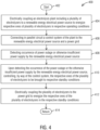
- FIG. 4 is a flow chart 400 depicting example steps (e.g., involving structural and/or operational relationships) in connection with one example embodiment of a disclosed method in the context of a system, such as disclosed above in the context of FIGs. 1 through 3 .
- step 404 allows electrically coupling an electrolysis plant comprising a plurality of electrolyzers to a renewable energy electrical power source to energize respective ones of the plurality of electrolyzers in respective operating conditions.
- step 406 allows connecting in parallel circuit a control system of the electrolysis plant to the renewable energy electrical power source and to a power grid.
- Step 408 allows detecting occurrence of a power outage or otherwise insufficient power supply by the renewable energy electrical power source.
- Step 410 allows energizing with the power grid the control system and controlling, by way of the control system, the respective ones of the plurality of electrolyzers to be brought to respective standby conditions upon detecting occurrence of the power outage or the otherwise insufficient power supply by the renewable energy electrical power source.
- step 412 Prior to a return step 414, allows electrically coupling the plurality of electrolyzers to the power grid to energize the respective ones of the plurality of electrolyzers in the respective standby conditions.
- FIG. 5 is a flow chart 500 depicting further example steps (e.g., involving further structural and/or operational relationships) in connection with one example embodiment of a disclosed method in the context of system, such as disclosed above in the context of FIG. 2 .
- step 504 allows electrically coupling a backup power supply to the control system.
- backup power supply may be a battery backup power supply, fuel cell system or both.
- Step 506 allows detecting occurrence of concurrent power outages or otherwise insufficient concurrent power supply by the renewable energy electrical power source and the power grid.
- step 508 Prior to a return step 510, upon detecting the occurrence of the concurrent power outages or otherwise insufficient concurrent power supply by the renewable energy electrical power source and the power grid, step 508 allows energizing, by way of the backup power supply, the control system.
- the method allows pre-selecting an energy rating and/or power rating of the backup power supply to provide a predefined amount of power to the control system over a period of time sufficiently long to bring the respective ones of the plurality of electrolyzers to respective idle conditions.
- the backup power supply is a battery backup power supply
- the period of time is in a range from approximately 7 minutes to approximately 15 minutes.
- disclosed embodiments are effective to provide cost-effective and reliable technical solutions in applications where a renewable energy power source and an electrolysis plant are connected to each other and where connectivity to a power grid is available but the power grid may not be connected or may be connected but lacks sufficient power to operate the electrolysis plant without additional local power generation.
- disclosed embodiments are designed to ensure that a control system of the electrolysis plant is reliably powered to bring electrolizers in the electrolysis plant to an appropriate state or condition, such as a standby condition or an idle condition notwithstanding the occurrence of any such conditions where power from the renewable power plant is not sufficient to run (e.g., operate) the electrolysis plant.
- disclosed embodiments permit connecting the control system in parallel circuit to the renewable energy power source and the power grid, and, optionally to a backup power supply, for example, in situations where the power quality provided by the renewable power source and the power grid is not sufficient to run the electrolyzers and provide sufficient power for the control system.
- disclosed embodiments permit reducing the required energy capacity of the backup power supply, and, in certain applications, it is contemplated that the backup power supply can be eliminated. Consequently, disclosed embodiments are conducive to an implementation that permits cost and space savings, compared to designs involving, for example, a high-capacity Uninterruptible Power Supply (UPS) system, as is generally the case in certain known implementations.
- UPS Uninterruptible Power Supply
Landscapes
- Chemical & Material Sciences (AREA)
- Engineering & Computer Science (AREA)
- Power Engineering (AREA)
- Organic Chemistry (AREA)
- Materials Engineering (AREA)
- Metallurgy (AREA)
- Electrochemistry (AREA)
- Business, Economics & Management (AREA)
- Emergency Management (AREA)
- Chemical Kinetics & Catalysis (AREA)
- Inorganic Chemistry (AREA)
- Electrolytic Production Of Non-Metals, Compounds, Apparatuses Therefor (AREA)
- Supply And Distribution Of Alternating Current (AREA)
Priority Applications (4)
| Application Number | Priority Date | Filing Date | Title |
|---|---|---|---|
| EP23171279.5A EP4459820A1 (de) | 2023-05-03 | 2023-05-03 | System und verfahren für eine elektrolyseanlage, die mit einer erneuerbaren energiequelle und einem stromnetz verbunden ist |
| CN202480029395.XA CN121039917A (zh) | 2023-05-03 | 2024-04-09 | 用于与可再生能源电源和电网互连的电解厂的系统和方法 |
| PCT/EP2024/059575 WO2024227563A1 (en) | 2023-05-03 | 2024-04-09 | System and method for electrolysis plant interconnected to renewable energy power source and power grid |
| EP24716822.2A EP4690407A1 (de) | 2023-05-03 | 2024-04-09 | System und verfahren für eine elektrolyseanlage, die mit einer erneuerbaren energiequelle und einem stromnetz verbunden ist |
Applications Claiming Priority (1)
| Application Number | Priority Date | Filing Date | Title |
|---|---|---|---|
| EP23171279.5A EP4459820A1 (de) | 2023-05-03 | 2023-05-03 | System und verfahren für eine elektrolyseanlage, die mit einer erneuerbaren energiequelle und einem stromnetz verbunden ist |
Publications (1)
| Publication Number | Publication Date |
|---|---|
| EP4459820A1 true EP4459820A1 (de) | 2024-11-06 |
Family
ID=86328752
Family Applications (2)
| Application Number | Title | Priority Date | Filing Date |
|---|---|---|---|
| EP23171279.5A Withdrawn EP4459820A1 (de) | 2023-05-03 | 2023-05-03 | System und verfahren für eine elektrolyseanlage, die mit einer erneuerbaren energiequelle und einem stromnetz verbunden ist |
| EP24716822.2A Pending EP4690407A1 (de) | 2023-05-03 | 2024-04-09 | System und verfahren für eine elektrolyseanlage, die mit einer erneuerbaren energiequelle und einem stromnetz verbunden ist |
Family Applications After (1)
| Application Number | Title | Priority Date | Filing Date |
|---|---|---|---|
| EP24716822.2A Pending EP4690407A1 (de) | 2023-05-03 | 2024-04-09 | System und verfahren für eine elektrolyseanlage, die mit einer erneuerbaren energiequelle und einem stromnetz verbunden ist |
Country Status (3)
| Country | Link |
|---|---|
| EP (2) | EP4459820A1 (de) |
| CN (1) | CN121039917A (de) |
| WO (1) | WO2024227563A1 (de) |
Families Citing this family (1)
| Publication number | Priority date | Publication date | Assignee | Title |
|---|---|---|---|---|
| US20250062636A1 (en) * | 2023-08-15 | 2025-02-20 | Air Products And Chemicals, Inc. | Method and System for Emergency Backup Power |
Citations (4)
| Publication number | Priority date | Publication date | Assignee | Title |
|---|---|---|---|---|
| US20120175952A1 (en) * | 2008-10-30 | 2012-07-12 | Next Hydrogen Corporation | Power dispatch system for electrolytic production of hydrogen from wind power |
| CN114481179A (zh) * | 2021-12-25 | 2022-05-13 | 智寰(北京)氢能科技有限公司 | 中压直流汇集型可再生能源发电制氢系统及其工作方法 |
| CN114990601A (zh) * | 2022-06-13 | 2022-09-02 | 潍柴动力股份有限公司 | 一种电能存储方法及装置 |
| WO2023036387A1 (en) * | 2021-09-07 | 2023-03-16 | Vestas Wind Systems A/S | Hydrogen electrolyser system based on a wind turbine generator |
-
2023
- 2023-05-03 EP EP23171279.5A patent/EP4459820A1/de not_active Withdrawn
-
2024
- 2024-04-09 CN CN202480029395.XA patent/CN121039917A/zh active Pending
- 2024-04-09 WO PCT/EP2024/059575 patent/WO2024227563A1/en not_active Ceased
- 2024-04-09 EP EP24716822.2A patent/EP4690407A1/de active Pending
Patent Citations (4)
| Publication number | Priority date | Publication date | Assignee | Title |
|---|---|---|---|---|
| US20120175952A1 (en) * | 2008-10-30 | 2012-07-12 | Next Hydrogen Corporation | Power dispatch system for electrolytic production of hydrogen from wind power |
| WO2023036387A1 (en) * | 2021-09-07 | 2023-03-16 | Vestas Wind Systems A/S | Hydrogen electrolyser system based on a wind turbine generator |
| CN114481179A (zh) * | 2021-12-25 | 2022-05-13 | 智寰(北京)氢能科技有限公司 | 中压直流汇集型可再生能源发电制氢系统及其工作方法 |
| CN114990601A (zh) * | 2022-06-13 | 2022-09-02 | 潍柴动力股份有限公司 | 一种电能存储方法及装置 |
Also Published As
| Publication number | Publication date |
|---|---|
| CN121039917A (zh) | 2025-11-28 |
| EP4690407A1 (de) | 2026-02-11 |
| WO2024227563A1 (en) | 2024-11-07 |
Similar Documents
| Publication | Publication Date | Title |
|---|---|---|
| TWI907366B (zh) | 產氫之模組系統及其操作方法 | |
| JP6790071B2 (ja) | 発電システム、パワーコンディショナ、電力制御装置、電力制御方法及び電力制御プログラム | |
| US11073807B2 (en) | Method and apparatus for activation and de-activation of power conditioners in distributed resource island systems using low voltage AC | |
| JP6019614B2 (ja) | 蓄電制御装置、蓄電制御装置の制御方法、プログラム、および蓄電システム | |
| US7821159B2 (en) | Metering pump power source | |
| CN105978008B (zh) | 一种具有风场黑启动功能的液流电池储能系统及其工作方法 | |
| EP2830186B1 (de) | Batterieheizersysteme und Verfahren | |
| US20190214824A1 (en) | Power generation system and related method of operating the power generation system | |
| CN101262145A (zh) | 连接到电网的不间断电源 | |
| CN114844079B (zh) | 基于风光氢储多能互补的综合能源系统及控制方法 | |
| KR100776353B1 (ko) | 수소에너지를 이용한 독립형 에너지 시스템 | |
| EP4459820A1 (de) | System und verfahren für eine elektrolyseanlage, die mit einer erneuerbaren energiequelle und einem stromnetz verbunden ist | |
| WO2017164977A1 (en) | Power generation system having variable speed engine and method for cranking the variable speed engine | |
| CN105703391A (zh) | 发电系统和操作发电系统的相关方法 | |
| CN103683466B (zh) | 一种基于现有光伏控制器的应急直供离网光伏供电系统 | |
| CN110932333A (zh) | 一种配电系统 | |
| JP6391473B2 (ja) | 蓄電池システム | |
| JP5864247B2 (ja) | 発電装置 | |
| CN112803579A (zh) | 新能源电站与火力发电厂厂用电及保安电源互补的系统及方法 | |
| JP6209337B2 (ja) | 給電システム、給電プログラムおよび給電方法 | |
| Reddy et al. | Integration and Implementation of Renewable Energy based Charging Station | |
| JPS6270918A (ja) | 燃料電池発電システムの運転方法 | |
| JP6507294B2 (ja) | 電力制御装置、電力制御方法、および電力制御システム | |
| CN103219787A (zh) | 一种可扩展的燃料电池应急发电系统 | |
| Hong et al. | The integrated operation method of emergency generator system for commercial building applied DC distribution system |
Legal Events
| Date | Code | Title | Description |
|---|---|---|---|
| PUAI | Public reference made under article 153(3) epc to a published international application that has entered the european phase |
Free format text: ORIGINAL CODE: 0009012 |
|
| STAA | Information on the status of an ep patent application or granted ep patent |
Free format text: STATUS: THE APPLICATION HAS BEEN PUBLISHED |
|
| AK | Designated contracting states |
Kind code of ref document: A1 Designated state(s): AL AT BE BG CH CY CZ DE DK EE ES FI FR GB GR HR HU IE IS IT LI LT LU LV MC ME MK MT NL NO PL PT RO RS SE SI SK SM TR |
|
| STAA | Information on the status of an ep patent application or granted ep patent |
Free format text: STATUS: THE APPLICATION IS DEEMED TO BE WITHDRAWN |
|
| 18D | Application deemed to be withdrawn |
Effective date: 20250507 |