EP4459658A2 - Tragbarer fehlerstromschutzschalter und/oder fehlerlichtbogenschutzschalter und verfahren zum betrieb davon - Google Patents
Tragbarer fehlerstromschutzschalter und/oder fehlerlichtbogenschutzschalter und verfahren zum betrieb davon Download PDFInfo
- Publication number
- EP4459658A2 EP4459658A2 EP24200852.2A EP24200852A EP4459658A2 EP 4459658 A2 EP4459658 A2 EP 4459658A2 EP 24200852 A EP24200852 A EP 24200852A EP 4459658 A2 EP4459658 A2 EP 4459658A2
- Authority
- EP
- European Patent Office
- Prior art keywords
- interrupting device
- power cable
- housing
- fault detection
- ground fault
- Prior art date
- Legal status (The legal status is an assumption and is not a legal conclusion. Google has not performed a legal analysis and makes no representation as to the accuracy of the status listed.)
- Pending
Links
Images






Classifications
-
- H—ELECTRICITY
- H01—ELECTRIC ELEMENTS
- H01H—ELECTRIC SWITCHES; RELAYS; SELECTORS; EMERGENCY PROTECTIVE DEVICES
- H01H83/00—Protective switches, e.g. circuit-breaking switches, or protective relays operated by abnormal electrical conditions otherwise than solely by excess current
- H01H83/02—Protective switches, e.g. circuit-breaking switches, or protective relays operated by abnormal electrical conditions otherwise than solely by excess current operated by earth fault currents
- H01H83/04—Protective switches, e.g. circuit-breaking switches, or protective relays operated by abnormal electrical conditions otherwise than solely by excess current operated by earth fault currents with testing means for indicating the ability of the switch or relay to function properly
-
- H—ELECTRICITY
- H01—ELECTRIC ELEMENTS
- H01H—ELECTRIC SWITCHES; RELAYS; SELECTORS; EMERGENCY PROTECTIVE DEVICES
- H01H83/00—Protective switches, e.g. circuit-breaking switches, or protective relays operated by abnormal electrical conditions otherwise than solely by excess current
- H01H83/20—Protective switches, e.g. circuit-breaking switches, or protective relays operated by abnormal electrical conditions otherwise than solely by excess current operated by excess current as well as by some other abnormal electrical condition
-
- H—ELECTRICITY
- H01—ELECTRIC ELEMENTS
- H01R—ELECTRICALLY-CONDUCTIVE CONNECTIONS; STRUCTURAL ASSOCIATIONS OF A PLURALITY OF MUTUALLY-INSULATED ELECTRICAL CONNECTING ELEMENTS; COUPLING DEVICES; CURRENT COLLECTORS
- H01R13/00—Details of coupling devices of the kinds covered by groups H01R12/70 or H01R24/00 - H01R33/00
- H01R13/66—Structural association with built-in electrical component
- H01R13/70—Structural association with built-in electrical component with built-in switch
- H01R13/713—Structural association with built-in electrical component with built-in switch the switch being a safety switch
- H01R13/7135—Structural association with built-in electrical component with built-in switch the switch being a safety switch with ground fault protector
-
- H—ELECTRICITY
- H02—GENERATION; CONVERSION OR DISTRIBUTION OF ELECTRIC POWER
- H02H—EMERGENCY PROTECTIVE CIRCUIT ARRANGEMENTS
- H02H1/00—Details of emergency protective circuit arrangements
- H02H1/0007—Details of emergency protective circuit arrangements concerning the detecting means
- H02H1/0015—Using arc detectors
-
- H—ELECTRICITY
- H01—ELECTRIC ELEMENTS
- H01H—ELECTRIC SWITCHES; RELAYS; SELECTORS; EMERGENCY PROTECTIVE DEVICES
- H01H83/00—Protective switches, e.g. circuit-breaking switches, or protective relays operated by abnormal electrical conditions otherwise than solely by excess current
- H01H83/20—Protective switches, e.g. circuit-breaking switches, or protective relays operated by abnormal electrical conditions otherwise than solely by excess current operated by excess current as well as by some other abnormal electrical condition
- H01H2083/201—Protective switches, e.g. circuit-breaking switches, or protective relays operated by abnormal electrical conditions otherwise than solely by excess current operated by excess current as well as by some other abnormal electrical condition the other abnormal electrical condition being an arc fault
-
- H—ELECTRICITY
- H02—GENERATION; CONVERSION OR DISTRIBUTION OF ELECTRIC POWER
- H02G—INSTALLATION OF ELECTRIC CABLES OR LINES, OR OF COMBINED OPTICAL AND ELECTRIC CABLES OR LINES
- H02G3/00—Installations of electric cables or lines or protective tubing therefor in or on buildings, equivalent structures or vehicles
- H02G3/02—Details
- H02G3/06—Joints for connecting lengths of protective tubing or channels, to each other or to casings, e.g. to distribution boxes; Ensuring electrical continuity in the joint
- H02G3/0616—Joints for connecting tubing to casing
- H02G3/0625—Joints for connecting tubing to casing with means for preventing disengagement of conductors
- H02G3/065—Joints for connecting tubing to casing with means for preventing disengagement of conductors with means biting into the conductor-insulation, e.g. teeth-like elements or gripping fingers
Definitions
- Embodiments relate to auto-monitoring / power denial (AM/PD) devices, and more specifically, portable AM/PD devices.
- AM/PD auto-monitoring / power denial
- the module includes a printed circuit board (PCB) and a bus bar located on the PCB.
- the bus bar includes one or more bus bar contacts.
- the module further includes one or more contact arms having one or more moveable contacts configured to be in a first position and a second position, wherein when in the first position the one or more moveable contacts are in physical contact with the one or more bus bar contacts and when in the second position the one or more moveable contacts are physically separated from the one or more bus bar contacts.
- the module further includes a coil assembly located on the PCB, the coil assembly is coupled to an actuating device, wherein the actuating device is coupled to the one or more contact arms. Wherein the coil assembly, via the actuating device, moves the one or more moveable contacts from the first position to the second position.
- a portable circuit interrupting device including a housing having a bottom portion.
- the portable circuit interrupting device further includes one or more plugs.
- the bottom portion of the housing includes a threaded portion configured to receive a cap and an aperture configured to receive a power cable.
- the threaded portion includes a compression tab configured to compress the power cable as the threaded portion receives the cap.
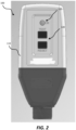
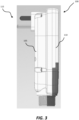
- Figs. 1-3 illustrate an auto-monitoring / power denial (AM/PD) device 100 according to some embodiments.
- the device 100 is a portable AM/PD device.
- the AM/PD devices disclosed herein may incorporate ground fault circuit interrupting (GFCI) features and/or arc fault circuit interrupting (AFCI) features.
- GFCI ground fault circuit interrupting
- AFCI arc fault circuit interrupting
- the AM/PD devices (and features) disclosed herein may be incorporated into generator units and/or in-wall units.
- the AM/PD device 100 may include a rear or base housing 105 and a front housing 110.
- the rear housing 105 includes one or more electrical plugs 115 configured to be received by an electrical outlet.
- the rear housing 105 may include apertures configured to receive one or more user-actuated inputs 120 (for example, buttons such as a TEST button and/or a RESET button) and one or more indicators 125.
- one or more user-actuated inputs 120 for example, buttons such as a TEST button and/or a RESET button
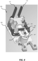
- Fig. 4 illustrates a module 200 of the AM/PD device 100 with the rear housing 105 and the front housing 110 removed for illustrative purposes, according to some embodiments.
- the module 200 includes a primary printed circuit board (PCB), or primary board, 205.
- the primary board 205 provides control and physical support for most of the working components included in the AM/PD device 100.
- a top surface of the primary board 205 provides support for an interrupting device 210, which is operable to trigger a self-test detailed below.
- the interrupting device 210 may be configured to interrupt an electrical connection between the line (for example, via the one or more electrical plugs 115) to the load (for example, via power cable 815 of Fig. 8 ).
- the interrupting device 210 may include contact arms 212 (including a first contact arm 212a and a second contact arm 212b) for providing the electrical connection between the line (for example, via the one or more electrical plugs 115) and the load (for example, via power cable 815 of Fig. 8 ).
- the contact arms 212a and 212b are biased away from respective contacts.
- the module 200 and/or the interrupting device 210 may further include a coil assembly 215 having one or more coils.
- the coil assembly 215 is physically supported by the primary PCB 205.
- the module 200 may further include one or more sense transformers 217 configured to sense one or more electrical characteristics (for example, a current) through contact arms 212 (and thus an electrical characteristic from the line to the load).
- one or more sense transformers 217 configured to sense one or more electrical characteristics (for example, a current) through contact arms 212 (and thus an electrical characteristic from the line to the load).
- Fig. 5 illustrates the module 200 of the AM/PD device 100 with the front housings 110 removed for illustrative purposes, according to some embodiments.
- the primary board 205 may further provide support for the user-actuated inputs 120, as well as power inputs 220 including a line neutral input 220a, a ground input 220b, and a line hot input 220c.
- the power inputs 220 are configured to electrical connect to the corresponding line, neutral, and ground of a power cable.
- the GFCI/AFCI device may have more power inputs 220.
- the primary PCB 205 may further include a plurality of surface mounted components, including one or more circuit components and/or a control circuit 600 (illustrated as a block diagram in Fig. 6 ).
- the control circuit 600 is configured to provide sensing and/or operational control over the AM/PD device 100.
- the control circuit 600 may include a controller 605.
- the controller 605 is electrically and/or communicatively connected to a variety of modules or components of the AM/PD device 100.
- the controller 605 is connected to the interrupting device 210 and the coil assembly 215.
- the controller 605 includes a plurality of electrical and electronic components that provide power, operational control, and protection to the components and modules within the controller 605 and/or the AM/PD device 100.
- the controller 605 includes, among other things, an electronic processor 610 (for example, a microprocessor or another suitable programmable device) and memory 615.
- the memory 615 includes, for example, a program storage area and a data storage area.
- the program storage area and the data storage area can include combinations of different types of memory, such as read-only memory (ROM), random access memory (RAM).
- ROM read-only memory
- RAM random access memory
- Various non-transitory computer readable media for example, magnetic, optical, physical, or electronic memory may be used.
- the electronic processor 610 is communicatively coupled to the memory 615 and executes software instructions that are stored in the memory 615, or stored on another non-transitory computer readable medium such as another memory or a disc.
- the software may include one or more applications, program data, filters, rules, one or more program modules, and other executable instructions.
- the controller 605 further includes an arc fault detection circuit 620.
- the arc fault detection circuit 620 may be a separate component, removed from the controller 605. In such an embodiment, the arc fault detection circuit 620 may still be electrical and/or communicative communication with the controller 605.
- the arc fault detection circuit 620 is configured to analyze electrical signals output by the sense transformer(s) 217. Moreover, the arc fault detection circuit 620 is configured to determine whether an arc fault has occurred based on the analysis of electrical signals received from the sense transformer(s) 217. In some embodiments, the arc fault detection circuit 620 is configured to transmit a signal indicative of the occurrence of an arc fault. In such embodiments, the controller 605 may be configured to trip the AM/PD device 100 in response to receiving the arc fault detection signal. For example, the controller 605 may control the interrupting device 210 (for example, to interrupt the flow of line power from the line terminal to the load terminal, such as by interrupting the flow of power from the power cable to the electrical plugs) in response to receiving the arc fault detection signal
- the arc fault detection circuit 620 is further configured to perform an AFCI self-test. In such embodiments, the arc fault detection circuit 620 is configured to report the results of the AFCI self-test to the controller 605. In some embodiments, the arc fault detection circuit 620 is configured to perform the AFCI self-test periodically, intermittently, and/or on an on-demand basis. In some embodiments, the AFCI self-test may be performed in response to receiving an instruction from the controller 605.
- the controller 605 further includes a ground fault detection circuit 625. Although illustrated as being part (or a function block) of the controller 605, in other embodiments, the ground fault detection circuit 625 may be a separate component, removed from the controller 605. In such an embodiment, the ground fault detection circuit 625 may still be electrical and/or communicative communication with the controller 605.
- the ground fault detection circuit 625 is configured to analyze electrical signals output by the sense transformer(s) 217. Moreover, the ground fault detection circuit 625 is configured to determine whether a ground fault has occurred based on the analysis of electrical signals received from the sense transformer(s) 217. In some embodiments, the ground fault detection circuit 625is configured to transmit a signal indicative of the occurrence of a ground fault. In such embodiments, the controller 605 may be configured to trip the AM/PD device 100 in response to receiving the ground fault detection signal. For example, the controller 605 may control the interrupting device 210 (for example, to interrupt the flow of line power from the line terminal to the load terminal, such as by interrupting the flow of power from the power cable to the electrical plugs) in response to receiving the ground fault detection signal.
- the interrupting device 210 for example, to interrupt the flow of line power from the line terminal to the load terminal, such as by interrupting the flow of power from the power cable to the electrical plugs
- the ground fault detection circuit 625 is further configured to perform a GFCI self-test. In such embodiments, the ground fault detection circuit 625 is configured to report the results of the GFCI self-test to the controller 605. In some embodiments, the ground fault detection circuit 625 is configured to perform the GFCI self-test periodically, intermittently, and/or on an on-demand basis. In some embodiments, the GFCI self-test may be performed in response to receiving an instruction from the controller 605.
- the arc fault detection circuit 620 and the ground fault detection circuit 625 may be combined into a single circuit and/or component.
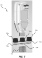
- Fig. 7 illustrates the AM/PD device 100 according to some embodiments.
- the AM/PD device 100 may include one or more grommets (or stoppers) 705 (for example, grommets 705a-705c having a variety of diameters, for example, but not limited to 12 gauge, 14 gauge, and 16 gauge).
- the grommets 705, along with a washer (or ring) 710 (for example, washer 710a-710c) and cap 715 are configured to secure power cables (for example, power cable 815 of Fig. 8 ) having varying diameters to the AM/PD device 100.
- grommet 705a, along with washer 710a are configured for a first power cable having a first diameter
- grommet 705b, along with washer 710b are configured for a second power cable having a second diameter
- grommet 705c, along with washer 710c are configured for a third power cable having a third diameter.
- more or less grommets and washers may be available for use with the AM/PD device 100.
- the grommets 705, the washer 710, and the cap 715 form a waterproof, or water resistant, seal between the power cable and AM/PD device 100.
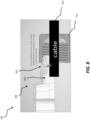
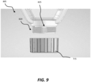
- Figs. 8 and 9 illustrate a bottom portion 805 of the AM/PD device 100 according to some embodiments.
- the bottom portion 805 includes an aperture 810 configured to receive the power cable 815.
- the bottom portion 805 further includes a threaded portion 820 and a compression tab 825.
- the compression tab 825 applies a force onto the power cable 815.
- the compression tab 825 includes an angle, such that as the cap 715 is screwed on, displacement of the compression tab 825 increases in order to accommodate various sizes of the power cable 815.
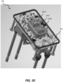
- Fig. 10 illustrates a top side view of the module 200 with housings removed for illustrative purposes, according to some embodiments.
- the one or more user-actuated inputs 120 include electronic switches 1005 (for example, a first electronic switch 1005a and a second electronic switch 1005b).
- the electronic switches 1005 are located on the primary board 205. By placing the electronic switches 1005 directly on the primary board 205, the manufacturing process may be simplified, and less calibration may be necessary.
- a user-interface (UI) gasket 1010 may be placed over the electronic switch 1005. The UI gasket 1010 may provide water proofing.
- UI user-interface
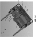
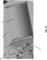
- Figs. 11A and 11B illustrate bottom side views of the module 200 with the housings removed for illustrative purposes, according to some embodiments.
- the module 200 is configurable with the embodiment disclosed in Fig. 15A .
- the module 200 may further include one or more bus bars 1100 (for example, bus bar 1100a and bus bar 1100b).
- the bus bars 1100 are mounted to the primary board 205 via a post 1105.
- the post 1105 may include a tab 1110 received by an aperture 1115 of the bus bars 1100.
- the bus bars 1100 are further directly coupled to the primary board 205 via riveting.
- the bus bars 1100 may each include a bus bar contact 1120 (for example, bus bar contact 1120a and bus bar contact 1120b).
- the first and second contact arms 212 may each include a movable contact 1125.
- the movable contacts 1125 are coupled to brush arms of the first and second contact arms 212.
- the moveable contacts 1125 are configured to be in physical contact with the bus bar contacts 1120 when in the RESET mode.
- the contact arms 212 further each include a slot for coupling the moveable contacts 1125 to the contact arms 212.
- the slots allow for heat dissipation and/or fine tuning of the placement of the moveable contacts 1125 (for example, in order to ensure proper connection with the contacts 1120 when in the RESET mode and a proper gap with contacts 1120 when the connection is open).
- the coil assembly (solenoid) 215 may be coupled to an actuating device 1130, which is coupled to the contact arms 212 (for example, via brush arms of the contact arms 212).
- the coil assembly 215 is coupled to the actuating device 1130 via a plunger 1135.
- the plunger 1135 is attached to the actuating device 1130 via a ball joint 1140.
- the ball joint 1140 may allow for compensation of any preload on either coil assembly 215 side or the actuating device 130 side.
- the plunger 1135 is extended from the coil assembly 215 in a first position.
- the moveable contacts 1125 are in physical contact with the bus bar contacts 1120, thus allowing current to flow from line (for example, lines/plugs 115) to the load (for example, load lines 1145).
- the plunger 1135 moves to a second position (as shown in Figs. 11A & 11B ) wherein the moveable contacts 1125 are separated (via actuation device 1130) from the bus bar contacts 1120.
- the bus bars 1100 may act as a heat sink configured to dissipate heat from the brush arms.
- the module 200 may further include a plate 1140 located under between the primary board 205 and the contacts 1125 and brush arms of the contact arms 212.
- the plate 1148 is comprised of metal and is configured to protect the primary board 205 from heat generated by the contacts 1125, brush arms of the contact arms 212, and/or bus bars 1100.
- the module 200 further includes a coil assembly frame 1150 configured to contain, or surround, the coil assembly 215.
- the coil assembly frame 1150 may include a coil assembly cap 1155 positioned within slots 1160 of the coil assembly frame 1150.
- the slots 1160 extend the entire length of the coil assembly frame 1150.
- the slots 1160 are at an angle other than ninety degrees (for example, less than ninety degrees). In such an embodiment, pressure is applied to the coil assembly cap 1155 in order to captivate the cap both physically and electrically to the coil assembly frame 1150.
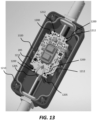
- the primary board 205 may include a plurality of slots 1200 configured to mate with one or more posts 1205, 1305 of respective housings 1210, 1310 (for example, rear housings).
- the slots 1200 and posts 1205, 1305 provide the ability for the primary board 205 (and therefore carrier assembly 200) to be placed within a variety of types of housings 1210, 1310.
- the slots 1200 of the primary board 205 is used to couple line terminals 1315a-1315c to the primary board 205.
- the primary board 205 may further include a plurality of holes 1212.
- the holes 1212 are configured to also mate with various posts 1205, 1305 of respective housings 1210, 1310 (for example, rear housings). Additionally, the holes 1212 may be used to connect wires for power lines (for example, as shown in the embodiment of Fig. 11B ).
- the housing 1210, 1310 further include a gasket (or O-ring) 1320.
- the gasket 1320 is compressed between the housing 1210, 1310 and a respective front housing.
- the gasket 1320 is further compressed via one or more fasteners (for example, screws) configured to couple a front housing to housing 1210, 1310.
- the gasket 130 may also be included in other embodiments disclosed herein, for example, but no limited to, the embodiment of Fig. 15A .
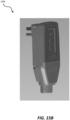
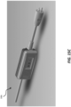
- Figs. 15A-15C illustrate various embodiments of the device 100 (including devices 100a-100c). Any of the above embodiments and/or features (for example, but not limited to, module 200) may be implemented into any device 100a-100c.
- device 100a is an in-wall unit configured to be permanently installed
- device 100b is a portable unit configured to be plugged into an electrical receptacle to receive line power
- device 100c is an inline unit configured to be located in line with an power cord (for example, an extension cord).
- an power cord for example, an extension cord
- Embodiments provide, among other things, a portable GFCI/AFCI device. Various features and advantages of the application are set forth in the following claims.
- a module of a circuit interrupting device comprising:
- the module wherein the coil assembly is coupled to the actuating device via a plunger and a ball joint.
- the module wherein one or more bus bar contacts and the one or more moveable contacts are located toward a center of the PCB.
- the module further comprising a plate located between the PCB and the one or more bus bar contacts and the one or more moveable contacts.
- the module further comprising a coil assembly frame surrounding the coil assembly.
- the coil assembly frame includes a coil assembly cap located within one or more slots of the coil assembly frame.
- the module wherein the module is configured to be placed in one of a plurality of auto-monitoring / power denial (AM/PD) devices.
- AM/PD auto-monitoring / power denial
- the module wherein the plurality of AM/PD devices include at least one selected from a group consisting of an in-wall unit, a portable unit, and an inline unit.
Landscapes
- Details Of Connecting Devices For Male And Female Coupling (AREA)
- Push-Button Switches (AREA)
- Mechanisms For Operating Contacts (AREA)
- Locating Faults (AREA)
- Testing Of Short-Circuits, Discontinuities, Leakage, Or Incorrect Line Connections (AREA)
Applications Claiming Priority (3)
| Application Number | Priority Date | Filing Date | Title |
|---|---|---|---|
| US202163241721P | 2021-09-08 | 2021-09-08 | |
| EP22868002.1A EP4399730A4 (de) | 2021-09-08 | 2022-09-07 | Tragbarer fehlerstromschutzschalter und/oder fehlerlichtbogenschutzschalter und verfahren zum betrieb davon |
| PCT/US2022/042767 WO2023038979A1 (en) | 2021-09-08 | 2022-09-07 | Portable ground fault circuit interrupter and/or arc fault circuity interrupter and method of operating the same |
Related Parent Applications (2)
| Application Number | Title | Priority Date | Filing Date |
|---|---|---|---|
| EP22868002.1A Division EP4399730A4 (de) | 2021-09-08 | 2022-09-07 | Tragbarer fehlerstromschutzschalter und/oder fehlerlichtbogenschutzschalter und verfahren zum betrieb davon |
| EP22868002.1A Division-Into EP4399730A4 (de) | 2021-09-08 | 2022-09-07 | Tragbarer fehlerstromschutzschalter und/oder fehlerlichtbogenschutzschalter und verfahren zum betrieb davon |
Publications (2)
| Publication Number | Publication Date |
|---|---|
| EP4459658A2 true EP4459658A2 (de) | 2024-11-06 |
| EP4459658A3 EP4459658A3 (de) | 2025-02-19 |
Family
ID=85385948
Family Applications (2)
| Application Number | Title | Priority Date | Filing Date |
|---|---|---|---|
| EP24200852.2A Pending EP4459658A3 (de) | 2021-09-08 | 2022-09-07 | Tragbarer fehlerstromschutzschalter und/oder fehlerlichtbogenschutzschalter und verfahren zum betrieb davon |
| EP22868002.1A Pending EP4399730A4 (de) | 2021-09-08 | 2022-09-07 | Tragbarer fehlerstromschutzschalter und/oder fehlerlichtbogenschutzschalter und verfahren zum betrieb davon |
Family Applications After (1)
| Application Number | Title | Priority Date | Filing Date |
|---|---|---|---|
| EP22868002.1A Pending EP4399730A4 (de) | 2021-09-08 | 2022-09-07 | Tragbarer fehlerstromschutzschalter und/oder fehlerlichtbogenschutzschalter und verfahren zum betrieb davon |
Country Status (6)
| Country | Link |
|---|---|
| US (2) | US12542251B2 (de) |
| EP (2) | EP4459658A3 (de) |
| CN (1) | CN118176559A (de) |
| CA (1) | CA3232594A1 (de) |
| MX (1) | MX2024002889A (de) |
| WO (1) | WO2023038979A1 (de) |
Families Citing this family (16)
| Publication number | Priority date | Publication date | Assignee | Title |
|---|---|---|---|---|
| US12093004B1 (en) | 2017-04-01 | 2024-09-17 | Smart Power Partners LLC | In-wall power adapter and method of implementing an in-wall power adapter |
| US12027968B2 (en) | 2017-04-01 | 2024-07-02 | John J. King | Power adapters and methods of implementing a power adapter |
| US10530597B1 (en) | 2017-04-01 | 2020-01-07 | Smart Power Partners LLC | System for controlling a plurality of power switches configured to apply power to devices |
| US10996645B1 (en) | 2017-04-01 | 2021-05-04 | Smart Power Partners LLC | Modular power adapters and methods of implementing modular power adapters |
| US12066848B1 (en) | 2019-06-30 | 2024-08-20 | Smart Power Partners LLC | In-wall power adaper adapted to receive a control attachment and method of implementing a power adapter |
| US12164350B1 (en) | 2019-06-30 | 2024-12-10 | Smart Power Partners LLC | Power adapter configured to provide power to a load |
| US11264769B1 (en) | 2019-06-30 | 2022-03-01 | Smart Power Partners LLC | Power adapter having contact elements in a recess and method of controlling a power adapter |
| US11201444B1 (en) | 2019-06-30 | 2021-12-14 | Smart Power Partners LLC | Power adapter having contact elements in a recess and method of controlling a power adapter |
| US10938168B2 (en) | 2019-06-30 | 2021-03-02 | Smart Power Partners LLC | In-wall power adapter and method of controlling the application of power to a load |
| US11043768B1 (en) | 2019-06-30 | 2021-06-22 | Smart Power Partners LLC | Power adapter configured to provide power to a load and method of implementing a power adapter |
| US11990712B1 (en) | 2019-06-30 | 2024-05-21 | Smart Power Partners LLC | Control attachment for a power adapter and method of implementing a control attachment |
| US12045071B1 (en) | 2019-06-30 | 2024-07-23 | Smart Power Partners LLC | In-wall power adapter having an outlet |
| US10917956B1 (en) | 2019-06-30 | 2021-02-09 | Smart Power Partners LLC | Control attachment configured to provide power to a load and method of configuring a control attachment |
| US11231730B1 (en) | 2019-06-30 | 2022-01-25 | Smart Power Power LLC | Control attachment for a power adapter configured to control power applied to a load |
| US10965068B1 (en) | 2019-06-30 | 2021-03-30 | Smart Power Partners LLC | In-wall power adapter having an outlet and method of controlling an in-wall power adapter |
| US12300948B2 (en) | 2021-11-03 | 2025-05-13 | Smart Power Partners LLC | Control module having a control circuit and adapted to be attached to a power adapter |
Family Cites Families (15)
| Publication number | Priority date | Publication date | Assignee | Title |
|---|---|---|---|---|
| DE2618347A1 (de) | 1976-04-27 | 1977-11-17 | Albert Blum | Kabeleinfuehrung bei elektrotechnischen geraeten, insbesondere elektromotorisch angetriebenen tauchpumpen |
| DE3519014A1 (de) | 1985-05-25 | 1986-11-27 | Anton Hummel Gmbh Metallwarenfabrik, 7808 Waldkirch | Kabelverschraubung |
| GB2238921A (en) * | 1989-12-07 | 1991-06-12 | Wellong Trading Ltd | Ground fault circuit interrupter |
| US5661623A (en) * | 1993-09-02 | 1997-08-26 | Hubbell Corporation | Ground fault circuit interrupter plug |
| US6122155A (en) | 1997-04-22 | 2000-09-19 | Tower Manufacturing Corporation | Mini appliance leakage current interrupter |
| US8514529B1 (en) * | 2000-11-21 | 2013-08-20 | Pass & Seymour, Inc. | Electrical wiring device |
| CN201425995Y (zh) | 2009-05-27 | 2010-03-17 | 中山市开普电器有限公司 | 具有漏电保护功能的电源插头 |
| US9774181B2 (en) * | 2012-03-16 | 2017-09-26 | Hubbell Incorporated | Enhanced auto-monitoring circuit and method for an electrical device |
| US8568152B1 (en) * | 2012-04-19 | 2013-10-29 | Pass & Seymour, Inc. | Shutter assembly for electrical devices |
| US9077177B2 (en) | 2013-09-24 | 2015-07-07 | Shanghai Yunyuan Electric Appliance Co. Ltd | Portable ground fault circuit breaker |
| US9466971B2 (en) * | 2014-01-24 | 2016-10-11 | Tower Mfg Corp | Mini appliance leakage current interrupter circuit and housing embodiments |
| US10916935B2 (en) * | 2017-11-28 | 2021-02-09 | Tower Manufacturing Corp | Leakage current detection and interruption (LCDI) device with ignition containment features |
| US11309667B2 (en) | 2017-12-07 | 2022-04-19 | Hubbell Incorporated | Shallow electrical protection device (GFCI, AFCI, and AFCI/GFCI) system and method |
| US11444447B2 (en) * | 2019-11-26 | 2022-09-13 | Carling Technologies, Inc. | Ground fault circuit breaker with remote testing capability |
| US11728595B2 (en) * | 2020-01-22 | 2023-08-15 | Hubbell Incorporated | Ground fault circuit interrupters and connectors for use with same |
-
2022
- 2022-09-07 MX MX2024002889A patent/MX2024002889A/es unknown
- 2022-09-07 EP EP24200852.2A patent/EP4459658A3/de active Pending
- 2022-09-07 WO PCT/US2022/042767 patent/WO2023038979A1/en not_active Ceased
- 2022-09-07 EP EP22868002.1A patent/EP4399730A4/de active Pending
- 2022-09-07 CA CA3232594A patent/CA3232594A1/en active Pending
- 2022-09-07 CN CN202280072892.9A patent/CN118176559A/zh active Pending
- 2022-09-07 US US17/939,675 patent/US12542251B2/en active Active
-
2025
- 2025-02-27 US US19/065,128 patent/US20250201504A1/en active Pending
Also Published As
| Publication number | Publication date |
|---|---|
| EP4459658A3 (de) | 2025-02-19 |
| CN118176559A (zh) | 2024-06-11 |
| US12542251B2 (en) | 2026-02-03 |
| CA3232594A1 (en) | 2023-03-16 |
| MX2024002889A (es) | 2024-03-22 |
| US20250201504A1 (en) | 2025-06-19 |
| EP4399730A4 (de) | 2025-02-19 |
| EP4399730A1 (de) | 2024-07-17 |
| US20230075542A1 (en) | 2023-03-09 |
| WO2023038979A8 (en) | 2024-06-06 |
| WO2023038979A1 (en) | 2023-03-16 |
Similar Documents
| Publication | Publication Date | Title |
|---|---|---|
| EP4459658A2 (de) | Tragbarer fehlerstromschutzschalter und/oder fehlerlichtbogenschutzschalter und verfahren zum betrieb davon | |
| US5481235A (en) | Conducting spring for a circuit interrupter test circuit | |
| CN1224992C (zh) | 接地故障反向错误接线电路中断器 | |
| US8605402B2 (en) | Heat sensor responsive to electrical overloads | |
| US5572396A (en) | Electric service safety disconnect apparatus with overvoltage and overcurrent protection | |
| CA2292088C (en) | Method and apparatus for testing an arcing fault circuit interrupter | |
| JPH08512427A (ja) | 接地故障モジュール導体およびそのためのベース | |
| CA2833146C (en) | Electrical load control with fault protection | |
| MXPA03012016A (es) | Receptaculo interruptor de circuito con falla a tierra que tiene un medio de bloqueo. | |
| US9640969B2 (en) | Arc fault circuit interrupter | |
| MXPA03012017A (es) | Un interruptor de circuito con falla a tierra sin contactos puente que tiene un medio para bloquear automaticamente una abertura de cara a un receptaculo protegido cuando esta desconectado. | |
| US8159803B2 (en) | Heat actuated interrupter receptacle | |
| CA2515059A1 (en) | Circuit interrupting device and system utilizing electromechanical reset | |
| US20050275981A1 (en) | GFCI wiring device with integral relay module | |
| US20100308943A1 (en) | Residual-current circuit breaker | |
| US20070279162A1 (en) | Ground-fault circuit interrupter with reverse wiring protection | |
| WO2004070751A2 (en) | Circuit interrupting device and system utilizing bridge contact mechanism and reset lockout | |
| US6678131B2 (en) | Arc-safe electrical receptacles | |
| US7612973B2 (en) | GFCI receptacle with single button for test-reset function | |
| US7554781B1 (en) | Protective device with an auxiliary switch | |
| US4164771A (en) | Wireless emergency power interrupting system for multibranch circuits | |
| CN217061960U (zh) | 漏电断路器 | |
| CN217641167U (zh) | 一种电子式漏电断路器 | |
| US20250015612A1 (en) | Leakage current protection device with charging power output | |
| KR100423887B1 (ko) | 리셉터클 |
Legal Events
| Date | Code | Title | Description |
|---|---|---|---|
| PUAI | Public reference made under article 153(3) epc to a published international application that has entered the european phase |
Free format text: ORIGINAL CODE: 0009012 |
|
| STAA | Information on the status of an ep patent application or granted ep patent |
Free format text: STATUS: THE APPLICATION HAS BEEN PUBLISHED |
|
| AC | Divisional application: reference to earlier application |
Ref document number: 4399730 Country of ref document: EP Kind code of ref document: P |
|
| AK | Designated contracting states |
Kind code of ref document: A2 Designated state(s): AL AT BE BG CH CY CZ DE DK EE ES FI FR GB GR HR HU IE IS IT LI LT LU LV MC MK MT NL NO PL PT RO RS SE SI SK SM TR |
|
| REG | Reference to a national code |
Ref country code: DE Ref legal event code: R079 Free format text: PREVIOUS MAIN CLASS: H01H0085060000 Ipc: H01R0013713000 |
|
| PUAL | Search report despatched |
Free format text: ORIGINAL CODE: 0009013 |
|
| AK | Designated contracting states |
Kind code of ref document: A3 Designated state(s): AL AT BE BG CH CY CZ DE DK EE ES FI FR GB GR HR HU IE IS IT LI LT LU LV MC MK MT NL NO PL PT RO RS SE SI SK SM TR |
|
| RIC1 | Information provided on ipc code assigned before grant |
Ipc: H02G 3/06 20060101ALN20250110BHEP Ipc: H01H 83/20 20060101ALI20250110BHEP Ipc: H01R 13/713 20060101AFI20250110BHEP |
|
| STAA | Information on the status of an ep patent application or granted ep patent |
Free format text: STATUS: REQUEST FOR EXAMINATION WAS MADE |
|
| 17P | Request for examination filed |
Effective date: 20250813 |
|
| GRAP | Despatch of communication of intention to grant a patent |
Free format text: ORIGINAL CODE: EPIDOSNIGR1 |
|
| STAA | Information on the status of an ep patent application or granted ep patent |
Free format text: STATUS: GRANT OF PATENT IS INTENDED |
|
| RIC1 | Information provided on ipc code assigned before grant |
Ipc: H01R 13/713 20060101AFI20260213BHEP Ipc: H01H 83/20 20060101ALI20260213BHEP Ipc: H02G 3/06 20060101ALN20260213BHEP |
|
| INTG | Intention to grant announced |
Effective date: 20260302 |