EP4459593A1 - Method for determining loss of control of a surrounding vehicle - Google Patents
Method for determining loss of control of a surrounding vehicle Download PDFInfo
- Publication number
- EP4459593A1 EP4459593A1 EP23171928.7A EP23171928A EP4459593A1 EP 4459593 A1 EP4459593 A1 EP 4459593A1 EP 23171928 A EP23171928 A EP 23171928A EP 4459593 A1 EP4459593 A1 EP 4459593A1
- Authority
- EP
- European Patent Office
- Prior art keywords
- surrounding
- steering correction
- vehicle
- surrounding vehicle
- road
- Prior art date
- Legal status (The legal status is an assumption and is not a legal conclusion. Google has not performed a legal analysis and makes no representation as to the accuracy of the status listed.)
- Withdrawn
Links
Images




Classifications
-
- G—PHYSICS
- G08—SIGNALLING
- G08G—TRAFFIC CONTROL SYSTEMS
- G08G1/00—Traffic control systems for road vehicles
- G08G1/16—Anti-collision systems
- G08G1/166—Anti-collision systems for active traffic, e.g. moving vehicles, pedestrians, bikes
-
- G—PHYSICS
- G08—SIGNALLING
- G08G—TRAFFIC CONTROL SYSTEMS
- G08G1/00—Traffic control systems for road vehicles
- G08G1/09—Arrangements for giving variable traffic instructions
- G08G1/0962—Arrangements for giving variable traffic instructions having an indicator mounted inside the vehicle, e.g. giving voice messages
- G08G1/0967—Systems involving transmission of highway information, e.g. weather, speed limits
- G08G1/096733—Systems involving transmission of highway information, e.g. weather, speed limits where a selection of the information might take place
- G08G1/096758—Systems involving transmission of highway information, e.g. weather, speed limits where a selection of the information might take place where no selection takes place on the transmitted or the received information
-
- G—PHYSICS
- G08—SIGNALLING
- G08G—TRAFFIC CONTROL SYSTEMS
- G08G1/00—Traffic control systems for road vehicles
- G08G1/09—Arrangements for giving variable traffic instructions
- G08G1/0962—Arrangements for giving variable traffic instructions having an indicator mounted inside the vehicle, e.g. giving voice messages
- G08G1/0967—Systems involving transmission of highway information, e.g. weather, speed limits
- G08G1/096766—Systems involving transmission of highway information, e.g. weather, speed limits where the system is characterised by the origin of the information transmission
- G08G1/096775—Systems involving transmission of highway information, e.g. weather, speed limits where the system is characterised by the origin of the information transmission where the origin of the information is a central station
-
- G—PHYSICS
- G08—SIGNALLING
- G08G—TRAFFIC CONTROL SYSTEMS
- G08G1/00—Traffic control systems for road vehicles
- G08G1/09—Arrangements for giving variable traffic instructions
- G08G1/0962—Arrangements for giving variable traffic instructions having an indicator mounted inside the vehicle, e.g. giving voice messages
- G08G1/0967—Systems involving transmission of highway information, e.g. weather, speed limits
- G08G1/096766—Systems involving transmission of highway information, e.g. weather, speed limits where the system is characterised by the origin of the information transmission
- G08G1/096791—Systems involving transmission of highway information, e.g. weather, speed limits where the system is characterised by the origin of the information transmission where the origin of the information is another vehicle
-
- G—PHYSICS
- G08—SIGNALLING
- G08G—TRAFFIC CONTROL SYSTEMS
- G08G1/00—Traffic control systems for road vehicles
- G08G1/16—Anti-collision systems
- G08G1/167—Driving aids for lane monitoring, lane changing, e.g. blind spot detection
-
- G—PHYSICS
- G08—SIGNALLING
- G08G—TRAFFIC CONTROL SYSTEMS
- G08G1/00—Traffic control systems for road vehicles
- G08G1/01—Detecting movement of traffic to be counted or controlled
- G08G1/0104—Measuring and analyzing of parameters relative to traffic conditions
- G08G1/0108—Measuring and analyzing of parameters relative to traffic conditions based on the source of data
- G08G1/0112—Measuring and analyzing of parameters relative to traffic conditions based on the source of data from the vehicle, e.g. floating car data [FCD]
Definitions
- the present disclosure relates to a method for determining loss of control of a surrounding vehicle, a computer program product and a vehicle.
- a loss of control of vehicles driving on the road may lead to accidents involving other road users.
- Drivers losing control of their vehicle may invade other lanes.
- Other road users may not be aware that a driver has lost control of his vehicle until it is too late and an accident is inevitable.
- Even if other road users, such as drivers of other vehicles, take note of an unusual driving behavior of one or more surrounding vehicles, they may incorrectly assume that the driver of the vehicle is still in control, e.g., is only about to switch lanes or perform another drive action not posing any danger to other road users.
- a method for determining loss of control of a surrounding vehicle comprising:
- the method according to the first aspect of this disclosure thereby provides for a reliable determination of loss of control of a surrounding vehicle, which can aid road users in their driving behavior in order to prevent being involved in an accident. Also, as will be explained further below, the method may include informing other road users of the danger involved with a vehicle for which a loss of control was determined.
- the vehicle for which loss of control is determined is herein referred to as a surrounding vehicle because it is being located in the surrounding, for which the object information is received.
- the object information may include information such as the presence of an object in the surrounding and/or an absolute or relative position of the object in the surrounding.
- specific information about the object, in particular the surrounding vehicle may be included such as size and/or type of surrounding vehicle, e.g., motorbike, car or truck. Such specific information may be taken into consideration for determination of loss of control.
- the at least one steering correction parameter threshold may be predefined based at least on the specific information. For example, when the surrounding vehicle is large, such as a truck, the predefined threshold may be lower such that loss of control may be determined more reliably.
- such specific information about the object may be considered for determining possible drive actions, when loss of control of a surrounding vehicle is determined and as will be explained further below.
- a determination of loss of control of a surrounding vehicle may be understood herein as a prediction or identification.
- This means that the method may either identify the loss of control, meaning that the method came to the result that it is certain or almost certain that control of a surrounding vehicle by the driver or any possible autonomous system of that vehicle is lost. But it may also predict a loss of control meaning that it can give an indication that a loss of control in a surrounding vehicle may be happening but this must not be certain or almost certain.
- the method may also indicate a likelihood of loss of control, e.g., 50%, 60%, etc.
- a road user may be informed of the possible loss of control of the surrounding vehicle or not.
- a threshold value for the likelihood may be set to increase sensitivity for a possible alert raising to other road users.
- the method may be partially or entirely carried out by an ego vehicle, in particular one or more computers or computing units of the ego vehicle.
- other devices such as smartphones of pedestrians, vehicle infrastructure devices, etc. may also be considered for carrying out the method partially or entirely.
- the ego vehicle may detect objects in its surrounding by any detection means of the vehicle, such as sensors and/or cameras, for example.
- the object information thereby generated includes the information about detected objects in the surrounding.
- the surrounding of the vehicle may be defined by the environment of the ego vehicle that is being detectable through the detection means. Accordingly, the surrounding may change during driving of the ego vehicle.
- the objects detected may be one or more surrounding vehicles and the road that is being travelled by the surrounding vehicle and possibly by the ego vehicle.
- the road may be detected by means of detecting road lane marks, traffic barriers, etc., which are also referred to herein as road objects.
- the steering correction behavior of the surrounding vehicle may comprise one or more steering corrections, which the surrounding vehicle may take in the course of its driving.
- a steering correction may be understood as a drive action taken by the surrounding vehicle to bring the surrounding vehicle back onto the travelled road, in particular road lane.
- the steering correction behavior describes all the steering corrections taken by the surrounding vehicle in the course of a certain time period, which may be predefined such that it may be assigned to one driving situation of the surrounding vehicle, for which it can be assessed whether a loss of control occurred. Such a predefined time period may be provided by means of a determination timer as will be explained later in more detail.
- the steering corrections may be defined by at least one steering correction parameter such that they can be processed by the method. Examples of steering correction parameters will be explained further below.
- the one or more steering correction parameter defining the steering corrections of the surrounding vehicle are being compared to one or more respective predefined steering correction parameter thresholds.
- These thresholds may be based on experience or simulation, for example. Further, they may be configured such that, when the thresholds are met, the method may identify loss of control or at least based on the one or more thresholds give a prediction of a loss of control, e.g., when there are multiple steering correction parameters but not all thresholds are exceeded.
- the method of the first aspect may in particular be a computer implemented method. This means that at least one, multiple or all of the steps of the method may be carried out by one or more computers or computing units, which may be included in the ego vehicle. Different steps may be carried out by the same or by different computers.
- a computer is herein understood as a data processing system or apparatus, which can carry out the steps as defined by the method.
- the one or more computers may be configured as or provided inside of one more control units of the ego vehicle. These control units may also be configured to carry out other control operations than described by the method according to the first aspect of this disclosure.
- the detected objects in the surrounding may include at least one road object of the road.
- the method may further include calculating at least one distance of the surrounding vehicle or a bounding box fitted on the surrounding vehicle from the at least one road object, the calculated distance being used for determining the steering correction behavior.
- the method may determine the steering correction behavior relative to the road objects and thereby with high reliability.
- the at least one distance may be calculated at the beginning of the steering correction.
- the measured distance(s) indicate the steering correction that needs to be performed in order to bring the surrounding vehicle back onto its travelled road lane.
- the road objects used for this may be repetitive road objects. Repetitive road objects along the road may be placed along the entire or part of the road such that the steering correction behavior may be determined with respect to the same type of road object along the road while the surrounding vehicle is travelling that road.
- the at least one road object may be at least one road lane mark, in particular repetitive road lane marks, of a road lane of the road being travelled by the surrounding vehicle.
- Such one or more road lane marks may be interrupted and repeated along the road lane or a continuous road lane mark. Having road lane marks as road objects makes the method particularly reliable because these may be reliably detected and are widely provided on roads.
- the object information may be based on surrounding images of the objects in the surrounding captured by a camera and said surrounding images processed by an image processor to detect the relative position of the surrounding vehicle on the road.
- the ego vehicle may comprise such camera and/or image processor. Accordingly, the ego vehicle may capture the surrounding images and process them so as to detect the relative position of the surrounding vehicle on the road.
- the detected relative position may be relative or, in other words, with respect to the road objects. Images are reliable sources to detect the relative position of the objects in the surrounding of the ego vehicle. Processing them as a source for detection makes the method particularly reliable.
- the determining of the steering correction behavior may comprise determining a first steering correction and setting a determination timer for determination of further steering corrections within a time frame set by the determination timer.
- the steering correction behavior being determined based on multiple steering corrections and only within a set time frame has the advantage that the likelihood for false identification and poor predictions is decreased. For example, it may be required that the method determines at least two, three or more steering corrections within a narrow, specified time frame. This time frame may be specified such that it is a typical or maximum time frame, in which a loss of control may occur based on experience from recorded data or simulation.
- the determination timer When the determination timer runs out without having determined the required number of steering corrections and/or steering corrections of a magnitude, which based on the comparison indicate loss of control, within the set time frame, the determination timer may be reset. The determination timer may then be set once again if another steering correction is determined such that the previous steering corrections from the previous determination timer do not count towards the determination of the newly determined steering correction behavior because previously it was not determined that there may be a loss of control of that particular surrounding vehicle.
- the determination timer may be set if at least one steering correction parameter of the first steering correction is meeting at least one steering correction parameter threshold configured for setting the determination timer. This means that if a steering correction parameter threshold of a certain steering correction parameter of a steering correction is not met, the determination timer may not be set.
- the method is triggered with the setting of a determination timer if based on the steering corrections it can be excluded or most-likely be excluded that a loss of control may occur, i.e., when the steering corrections are based on controlled driving operations, such as switching lanes, for example. Accordingly, a computer carrying out the method is not loaded heavily and thereby usage of computing resources may be optimized.
- At least one steering correction parameter may be a steering correction magnitude parameter indicating the magnitude of the steering correction behavior.
- the steering correction magnitude may define the severity of the taken steering correction in terms of how much the surrounding vehicle is moving for that steering correction. This may indicate whether the steering correction is only minor in terms of magnitude, e.g., the driver of the surrounding vehicle has only briefly not performed a steering action to follow a curve of the road and corrected it, or if the steering correction is huge, e.g., the driver has for a longer period of time not paid attention to the traffic or road and performed a significant steering action to bring the surrounding vehicle back on the road lane to be travelled.
- the at least one steering correction magnitude parameter may be determined based on a magnitude of change of the at least one distance during travel of the surrounding vehicle. Using the distance between the surrounding vehicle or its bounding box and a road object allows for an easy and reliable determination of the steering correction magnitude.
- the at least one steering correction parameter may be a number of steering corrections parameter indicating a number of steering corrections per time.
- the number of steering corrections per time may be easily detected and is very reliable towards determining whether the surrounding vehicle has lost control. For example, when the number of steering corrections per time is big, this implies that the driver of the surrounding vehicle has difficulties controlling the vehicle indicating that he has lost control or may be losing control of the vehicle.
- the at least one steering correction parameter may be a steering correction duration parameter indicating the duration of at least one single steering correction.
- the duration of the single steering corrections is a further easily detectable and reliable determinant for the determination of loss of control of the surrounding vehicle. For example, very short or long steering corrections may indicate that the driver of the surrounding vehicle has difficulties in controlling the vehicle.
- the method may further comprise determining at least one drive action based on the predicted or identified loss of control to prevent collision with the surrounding vehicle.
- Such drive action may be communicated to the driver of the ego vehicle, e.g., displayed as text, symbol etc., or announced acoustically, such that the driver may take corresponding action.
- the determined drive action may be to slow down, brake, accelerate and/or switch lanes depending on the determined position of the surrounding vehicle with determined loss of control.
- the ego vehicle may be provided with autonomous driving capabilities.
- the autonomous driving capabilities may be partial, such as holding its travelled road lane and distance towards a vehicle ahead of it, or full, meaning fully autonomous driving capabilities, in which a passenger is not required to take any action to drive the ego vehicle. In such a case, the ego vehicle may autonomously perform the determined at least one drive action to prevent collision.
- the objects detected in the surroundings may further include at least one road object in the form of a road barrier, the detected road barrier being used for determining the drive action.
- the ego vehicle may thus consider the safest drive action given the position and possibly the likelihood of the loss of control of a surrounding vehicle as well as the position of road barriers on the road.
- the method may further comprise receiving weather information for the surrounding and predefining the at least one predefined steering correction parameter threshold according to the received weather information.
- weather information may be determined based on sensors on an ego vehicle, such as a temperature sensor, and include the temperature in the environment.
- the weather information may alternatively or additionally include weather forecasts, which may be received wirelessly, e.g., via the internet.
- the accuracy of the method in detecting loss of control of a surrounding vehicle may be further increased. For example, when snowy and/or icy road conditions are assumed based on the received weather information, the threshold may be lower because it is more likely that the driver of a surrounding vehicle loses control of the vehicle.
- the method may further comprise providing broadcasting instructions about the predicted or identified loss of control of the surrounding vehicle for other road users in the area.
- Other road users may be vehicles or passengers, for example.
- the broadcasting may be performed via wireless electronic communication, in particular via a cellular network. Such communication may be performed as Car2X or Car2Car communication, for example.
- the broadcasting may include also using the horn of the ego vehicle as communication means such that alert is raised to other road users acoustically.
- the method may further include receiving a measured speed of the surrounding vehicle, identifying whether the surrounding vehicle has stopped or not based on the measured speed, and providing broadcasting information about whether the surrounding vehicle has stopped or not for other road users in the area. Accordingly, the method may be performed further after a loss of control has been determined or not such that other road users may be informed of a potential accident or an occurred accident.
- a method for determining loss of control of a surrounding vehicle comprising the steps of the method according to the first aspect of this disclosure and at least one further step performed by an ego vehicle.
- a step may be, for example, the capturing of surrounding images of the objects in the surrounding by means of at least one camera of the ego vehicle.
- the processing of said surrounding images by an image processor of the ego vehicle may be a further step in the method of the second aspect of this disclosure.
- performing a determined drive action may be a step in the method of the second aspect.
- Another step of the method of the second aspect may be the broadcasting to other road users based on the provided broadcasting instructions, which may include information about the predicted or detected loss of control of the surrounding vehicle for other road users in the area. Also, measuring the speed of the surrounding vehicle and correspondingly broadcasting whether the vehicle has stopped or not to other road users based on the provided broadcasting information may be performed by the ego vehicle.
- the method of the second aspect of this disclosure may be carried out partially or entirely by the ego vehicle.
- a computer or control unit in the ego vehicle may carry out the method of the first aspect, while the other steps of the method of the second aspect are carried out by a corresponding camera for taking surrounding images in the surrounding, an autonomous driving control system for performing a drive action, a wireless communication system for broadcasting and/or a measuring unit for measuring the speed of the surrounding vehicle.
- a computer program product comprising instructions which, when the program is executed by a computer, cause the computer to carry out the method according to the first aspect of this disclosure.
- the computer program product may be a computer program as such, meaning a computer program consisting of or comprising a program code to be executed by the computer.
- the computer program product may be a product such as a data storage, on which the computer program is temporarily or permanently stored.
- a data processing apparatus comprising means for carrying out the method according to the first aspect of this disclosure.
- the data processing apparatus may execute or comprise the computer program product according to the third aspect of this disclosure.
- a vehicle comprising detection means for detecting objects in its surrounding and processing means for processing the data relating to the detected objects, the vehicle being configured to carry out the method according to the first aspect and/or the second aspect of this disclosure.
- the vehicle being configured to carry out the method according to the first and/or second aspect of this disclosure in particular means that the respective components of the vehicle are configured to carry out the respective steps of the method according to the first and/or second aspect of this disclosure.
- the vehicle may comprise the data processing apparatus according to the fourth aspect of this disclosure or a computer or computing unit, which may be part of or formed by a control unit of the vehicle.
- the method may include further components such as mentioned above, e.g., a camera as detection means, an image processor as or included in the processing means, an autonomous driving control system, a wireless communication system, a measuring unit, etc.
- Figure 1 illustrates a method 100 for determining loss of control LOC of a surrounding vehicle 20, such as the one shown in Fig. 7 .
- Loss of control LOC may occur when the driver or an autonomous driving system of the surrounding vehicle 20 is not able to fully control the surrounding vehicle 20 anymore, in particular without a risk that an accident may happen, e.g., due to the driver being under influence or the surrounding vehicle 20 swerving because of slippery roads, for example.
- the method 100 of this example is computer-implemented. This means that the method 100 may be carried out entirely or at least partially by one or more computers, which may in particular be included in an ego vehicle 10 (see Fig. 9 , for example), which may thereby carry out the method 100. However, the method 100 may include further steps performed by other means of the ego vehicle 10 as will be explained below.
- a first step 102 of the method 100 object information OI of a surrounding S of the ego vehicle 10 is being received (see Fig. 9 , for example).
- the surrounding S is represented here by a detection area of the ego vehicle 10, in which the ego vehicle 10 may detect objects.
- the object information OI comprises information about detected objects in the surrounding S, which includes the surrounding vehicle 20 and the road 30 being travelled by the surrounding vehicle 20 and the ego vehicle 10.
- the road 30 may be detected through one or more road objects 34 of the road 30, in particular at least one road lane mark of a road lane 32 of the road 30 being travelled by the surrounding vehicle 20 as being shown in Fig. 9 , for example.
- the information of the detected objects may comprise location information, in particular the absolute position or relative position of the surrounding vehicle 20 and the road 30 with respect to the ego vehicle 10 and/or to each other and/or to other objects in the surrounding S.
- the ego vehicle 10 may comprise corresponding detection means 12, such as one or more cameras, and processing means 14, such as an image processor, for processing the detection data recorded by the detection means 12, as may be taken from Fig. 3 schematically illustrating an ego vehicle 10 with its components.
- the detection of the objects in the surrounding S by means of the detection means 12 and/or the processing means 14 may be a step in the method 100.
- a second step 104 of the method 100 at least one distance D is being calculated between the surrounding vehicle 20 or a bounding box BB fitted on the surrounding vehicle 20 from the at least one road object 34.
- This distance D represents a deviation of the surrounding vehicle 20 from the road lane 32 and thereby a required steering correction SC to bring the surrounding vehicle 20 back onto its travelled road lane 32.
- the left and right distances D of the bounding box BB fitted on the surrounding vehicle 20 from a road lane mark of the travelled lane 32 is being calculated.
- the calculated distances D are now being used to determine a steering correction behavior SCB of the surrounding vehicle 20 in a third step 106 of the method 100.
- the steering correction behavior SCB may comprise one or more steering corrections SC, SC1, SC2, SC3 performed by the surrounding vehicle 20 and as exemplary illustrated in Figs. 7 and 8 , where Fig. 8 shows the start points of the performed steering corrections SC, SC 1, SC2, SC3, for which the above explained distances D from the road objects 34 may be determined to determine the steering correction magnitude parameters SCMP of each steering correction SC, SC1, SC2, SC3.
- a surrounding vehicle 20 with loss of control LOC is illustrated with its drive path along road 30, invading the opposite road lane 32 as indicated by the arrows illustrating the given direction of travel for each road lane 32.
- the surrounding vehicle 20 during travelling takes four steering actions SC1, SC2, SC3, SC4 in order to control the surrounding vehicle 20.
- These four steering actions SC1, SC2, SC3, SC4 are illustrated in Fig. 8 from the front and similar to Figs. 4 to 6 .
- distances D of the surrounding vehicle 20 may be calculated from the respective road objects 34 of the travelled road lane 32, in this case in the form of road lane markings.
- the respective steering actions SC1, SC2, SC3, SC4 are included in the steering correction behavior SCB by means of steering correction parameters SCP, which are defining the respective steering actions SC1, SC2, SC3, SC4.
- Such steering correction parameters SCP may be a steering correction magnitude parameter SCMP, a number of steering corrections parameter NSCP and a steering correction duration parameter SCDP, for example.
- Figs. 5 and 6 illustrate the determination of the steering correction behavior SCB in the third step 106 of the method 100 by determining a steering correction magnitude parameter SCMP as steering correction parameter SCP for the different steering corrections shown in Figs. 5 and 6 having different distances D.
- a higher steering correction magnitude parameter SCMP for Fig. 6 will be determined than for Fig. 5 , for example.
- the steering correction parameters SCP are being compared to at least one predefined steering correction parameter threshold SCPT.
- the predefined steering correction parameter threshold SCPT may require at least one or a number of steering corrections SC1, SC2, SC3, SC4 of a certain magnitude to determine a loss of control LOC.
- a loss of control LOC of the surrounding vehicle 20 is determined by means of prediction or identification. For example, loss of control LOC of the surrounding vehicle 20 may be predicted with a certain likelihood.
- a drive action DA may be determined for the ego vehicle 10 based on the predicted or identified loss of control LOC such that when the drive action DA is performed by the ego vehicle 10, a collision with the surrounding vehicle 20 may be avoided.
- the ego vehicle 10 may have an autonomous driving system 16 as depicted in Fig. 3 to perform the drive action DA.
- a further, non-depicted step of the method 100 may be to provide broadcasting instructions about the predicted or identified loss of control LOC of the surrounding vehicle 20 for other road users 40 (see Figs. 11, 12 ) in the area.
- Such broadcasting instructions may be carried out by a broadcasting system 18 of the ego vehicle 10 as depicted in Fig. 3 , such that it broadcasts the location of the surrounding vehicle 20 having the loss of control LOC and/or information about the loss of control LOC to the other road users 40 in the area.
- Each or single steps of the method 100 of Fig. 1 may be carried out for each determined steering correction SC1, SC2, SC3, SC4 of the surrounding vehicle 20. Determining steering corrections SC1, SC2, SC3, SC4 and carrying out the method 100 for every surrounding vehicle 20 in the surrounding S may put a high load onto a corresponding computer or computing unit of the ego vehicle 10. To limit the load imposed on a corresponding computer or computing unit of the ego vehicle 10 carrying out the method 100, the steps shown in Fig. 2 may be carried out within method 100.
- a first steering correction SC1 of a surrounding vehicle 20 is determined.
- the comparison of the steering correction parameter SCP for that first steering correction SC 1 with the at least one predefined steering correction parameter threshold SCPT is performed.
- a determination timer DT is set if the predefined steering correction parameter threshold SCPT is met by the steering correction parameter SCP of the first steering correction SC1.
- the third step 106 and the fourth step 108 are continued for further steering corrections SC2, SC3, SC4 for a time frame set by the determination timer DT.
- the method 100 is only carried out for a large part or in its entirety for surrounding vehicles 20, which by virtue of their first and further steering corrections SC1, SC2, etc. are considered to be significant enough that a loss of control LOC may occur and justifies carrying out method 100.
- Fig. 9 illustrates a driving scenario with a surrounding vehicle 20 losing control behind an ego vehicle 10 determining the loss of control LOC of the surrounding vehicle 20 in its surrounding S.
- the determined drive action DA may be to accelerate the ego vehicle 10 to gain distance from the surrounding vehicle 20.
- Fig. 10 illustrates a driving scenario with a surrounding vehicle 20 losing control in front of an ego vehicle 10 determining the loss of control LOC of the surrounding vehicle 20 in its surrounding S.
- the determined drive action DA may be to slow down the ego vehicle 10 to gain distance from the surrounding vehicle 20.
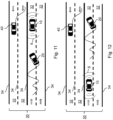
- Figs. 11 and 12 illustrate the same driving scenarios as Figs. 9 and 10 but with another road user 40 in form of another vehicle travelling on one of the oppositely directed road lanes 32 of the road 30.
- the ego vehicle 10 may broadcast the determined loss of control LOC to the other road user 40 such that he may take an action to avoid collision with the surrounding vehicle 20.
- the other road user 40 is switching the road lane 32 to gain distance from the surrounding vehicle 20.
- Figs. 13 and 14 illustrate different driving scenarios in which the ego vehicle 10 is measuring the speed V of the surrounding vehicle 20 to identify whether the surrounding vehicle 20 has stopped or not.
- the surrounding vehicle 20 has stopped and the ego vehicle 10 may include this information in its broadcasting.
- the ego vehicle 10 may broadcast this information to other road users 40 and/or call an ambulance based on the assumption that the surrounding vehicle 20 crashed.
- the surrounding vehicle 20 is continuing controlled driving.
- Figs. 15 and 16 show different driving scenarios, in which a surrounding vehicle 20 has lost control.
- Using different steering correction parameters SCP to define the individual steering corrections SC may be advantageous in these cases to better determine the steering correction behavior SCB.
- the steering corrections SC are smoother, taking a longer time to be performed.
- the steering corrections SC are aggressive because they are performed quickly.
- These steering corrections SC while having similar magnitudes, have a different duration and thus may be defined best when including the mentioned steering correction duration parameter SCDP.
Landscapes
- Physics & Mathematics (AREA)
- General Physics & Mathematics (AREA)
- Life Sciences & Earth Sciences (AREA)
- Atmospheric Sciences (AREA)
- Traffic Control Systems (AREA)
Abstract
Description
- The present disclosure relates to a method for determining loss of control of a surrounding vehicle, a computer program product and a vehicle.
- A loss of control of vehicles driving on the road may lead to accidents involving other road users. Drivers losing control of their vehicle may invade other lanes. Other road users may not be aware that a driver has lost control of his vehicle until it is too late and an accident is inevitable. Even if other road users, such as drivers of other vehicles, take note of an unusual driving behavior of one or more surrounding vehicles, they may incorrectly assume that the driver of the vehicle is still in control, e.g., is only about to switch lanes or perform another drive action not posing any danger to other road users.
- The above problem is at least partially solved or alleviated by the subject matter of the independent claims of the present disclosure, wherein further examples are incorporated in the dependent claims.
- According to a first aspect of this disclosure, there is provided a method for determining loss of control of a surrounding vehicle, the method comprising:
- receiving object information of a surrounding, the object information comprising information about detected objects in the surrounding, the objects including the surrounding vehicle and a road being travelled by the surrounding vehicle,
- determining a steering correction behavior of the surrounding vehicle, the steering correction behavior comprising at least one steering correction of the surrounding vehicle and comprising at least one steering correction parameter defining the at least one steering correction,
- comparing the at least one steering correction parameter to at least one predefined steering correction parameter threshold, and
- predicting or identifying loss of control of the surrounding vehicle based on the comparison.
- The method according to the first aspect of this disclosure thereby provides for a reliable determination of loss of control of a surrounding vehicle, which can aid road users in their driving behavior in order to prevent being involved in an accident. Also, as will be explained further below, the method may include informing other road users of the danger involved with a vehicle for which a loss of control was determined.
- The vehicle for which loss of control is determined is herein referred to as a surrounding vehicle because it is being located in the surrounding, for which the object information is received. The object information may include information such as the presence of an object in the surrounding and/or an absolute or relative position of the object in the surrounding. Further, specific information about the object, in particular the surrounding vehicle, may be included such as size and/or type of surrounding vehicle, e.g., motorbike, car or truck. Such specific information may be taken into consideration for determination of loss of control. For example, the at least one steering correction parameter threshold may be predefined based at least on the specific information. For example, when the surrounding vehicle is large, such as a truck, the predefined threshold may be lower such that loss of control may be determined more reliably. Also, such specific information about the object may be considered for determining possible drive actions, when loss of control of a surrounding vehicle is determined and as will be explained further below.
- A determination of loss of control of a surrounding vehicle may be understood herein as a prediction or identification. This means that the method may either identify the loss of control, meaning that the method came to the result that it is certain or almost certain that control of a surrounding vehicle by the driver or any possible autonomous system of that vehicle is lost. But it may also predict a loss of control meaning that it can give an indication that a loss of control in a surrounding vehicle may be happening but this must not be certain or almost certain. For example, based on the determined steering correction behavior and the comparison, the method may also indicate a likelihood of loss of control, e.g., 50%, 60%, etc. Depending on the likelihood, a road user may be informed of the possible loss of control of the surrounding vehicle or not. For example, a threshold value for the likelihood may be set to increase sensitivity for a possible alert raising to other road users.
- The method may be partially or entirely carried out by an ego vehicle, in particular one or more computers or computing units of the ego vehicle. However, other devices, such as smartphones of pedestrians, vehicle infrastructure devices, etc. may also be considered for carrying out the method partially or entirely.
- In the case of the ego vehicle, the ego vehicle may detect objects in its surrounding by any detection means of the vehicle, such as sensors and/or cameras, for example. The object information thereby generated includes the information about detected objects in the surrounding. The surrounding of the vehicle may be defined by the environment of the ego vehicle that is being detectable through the detection means. Accordingly, the surrounding may change during driving of the ego vehicle. The objects detected may be one or more surrounding vehicles and the road that is being travelled by the surrounding vehicle and possibly by the ego vehicle. The road may be detected by means of detecting road lane marks, traffic barriers, etc., which are also referred to herein as road objects.
- The steering correction behavior of the surrounding vehicle may comprise one or more steering corrections, which the surrounding vehicle may take in the course of its driving. A steering correction may be understood as a drive action taken by the surrounding vehicle to bring the surrounding vehicle back onto the travelled road, in particular road lane. In other words, the steering correction behavior describes all the steering corrections taken by the surrounding vehicle in the course of a certain time period, which may be predefined such that it may be assigned to one driving situation of the surrounding vehicle, for which it can be assessed whether a loss of control occurred. Such a predefined time period may be provided by means of a determination timer as will be explained later in more detail. The steering corrections may be defined by at least one steering correction parameter such that they can be processed by the method. Examples of steering correction parameters will be explained further below.
- In order to determine, e.g., predict or identify, loss of control of a surrounding vehicle, the one or more steering correction parameter defining the steering corrections of the surrounding vehicle are being compared to one or more respective predefined steering correction parameter thresholds. These thresholds may be based on experience or simulation, for example. Further, they may be configured such that, when the thresholds are met, the method may identify loss of control or at least based on the one or more thresholds give a prediction of a loss of control, e.g., when there are multiple steering correction parameters but not all thresholds are exceeded.
- The method of the first aspect may in particular be a computer implemented method. This means that at least one, multiple or all of the steps of the method may be carried out by one or more computers or computing units, which may be included in the ego vehicle. Different steps may be carried out by the same or by different computers. A computer is herein understood as a data processing system or apparatus, which can carry out the steps as defined by the method. The one or more computers may be configured as or provided inside of one more control units of the ego vehicle. These control units may also be configured to carry out other control operations than described by the method according to the first aspect of this disclosure.
- The detected objects in the surrounding may include at least one road object of the road. The method may further include calculating at least one distance of the surrounding vehicle or a bounding box fitted on the surrounding vehicle from the at least one road object, the calculated distance being used for determining the steering correction behavior. By calculating distances of the surrounding vehicle from road objects such as, for example, traffic barriers, the method may determine the steering correction behavior relative to the road objects and thereby with high reliability. The at least one distance may be calculated at the beginning of the steering correction. In this way, the measured distance(s) indicate the steering correction that needs to be performed in order to bring the surrounding vehicle back onto its travelled road lane. The road objects used for this may be repetitive road objects. Repetitive road objects along the road may be placed along the entire or part of the road such that the steering correction behavior may be determined with respect to the same type of road object along the road while the surrounding vehicle is travelling that road.
- The at least one road object may be at least one road lane mark, in particular repetitive road lane marks, of a road lane of the road being travelled by the surrounding vehicle. Such one or more road lane marks may be interrupted and repeated along the road lane or a continuous road lane mark. Having road lane marks as road objects makes the method particularly reliable because these may be reliably detected and are widely provided on roads.
- The object information may be based on surrounding images of the objects in the surrounding captured by a camera and said surrounding images processed by an image processor to detect the relative position of the surrounding vehicle on the road. In particular, the ego vehicle may comprise such camera and/or image processor. Accordingly, the ego vehicle may capture the surrounding images and process them so as to detect the relative position of the surrounding vehicle on the road. The detected relative position may be relative or, in other words, with respect to the road objects. Images are reliable sources to detect the relative position of the objects in the surrounding of the ego vehicle. Processing them as a source for detection makes the method particularly reliable.
- The determining of the steering correction behavior may comprise determining a first steering correction and setting a determination timer for determination of further steering corrections within a time frame set by the determination timer. The steering correction behavior being determined based on multiple steering corrections and only within a set time frame has the advantage that the likelihood for false identification and poor predictions is decreased. For example, it may be required that the method determines at least two, three or more steering corrections within a narrow, specified time frame. This time frame may be specified such that it is a typical or maximum time frame, in which a loss of control may occur based on experience from recorded data or simulation. When the determination timer runs out without having determined the required number of steering corrections and/or steering corrections of a magnitude, which based on the comparison indicate loss of control, within the set time frame, the determination timer may be reset. The determination timer may then be set once again if another steering correction is determined such that the previous steering corrections from the previous determination timer do not count towards the determination of the newly determined steering correction behavior because previously it was not determined that there may be a loss of control of that particular surrounding vehicle.
- The determination timer may be set if at least one steering correction parameter of the first steering correction is meeting at least one steering correction parameter threshold configured for setting the determination timer. This means that if a steering correction parameter threshold of a certain steering correction parameter of a steering correction is not met, the determination timer may not be set. By requiring that the steering correction parameter meets a certain threshold, it may be avoided that the method is triggered with the setting of a determination timer if based on the steering corrections it can be excluded or most-likely be excluded that a loss of control may occur, i.e., when the steering corrections are based on controlled driving operations, such as switching lanes, for example. Accordingly, a computer carrying out the method is not loaded heavily and thereby usage of computing resources may be optimized.
- At least one steering correction parameter may be a steering correction magnitude parameter indicating the magnitude of the steering correction behavior. The steering correction magnitude may define the severity of the taken steering correction in terms of how much the surrounding vehicle is moving for that steering correction. This may indicate whether the steering correction is only minor in terms of magnitude, e.g., the driver of the surrounding vehicle has only briefly not performed a steering action to follow a curve of the road and corrected it, or if the steering correction is huge, e.g., the driver has for a longer period of time not paid attention to the traffic or road and performed a significant steering action to bring the surrounding vehicle back on the road lane to be travelled.
- The at least one steering correction magnitude parameter may be determined based on a magnitude of change of the at least one distance during travel of the surrounding vehicle. Using the distance between the surrounding vehicle or its bounding box and a road object allows for an easy and reliable determination of the steering correction magnitude.
- The at least one steering correction parameter may be a number of steering corrections parameter indicating a number of steering corrections per time. The number of steering corrections per time may be easily detected and is very reliable towards determining whether the surrounding vehicle has lost control. For example, when the number of steering corrections per time is big, this implies that the driver of the surrounding vehicle has difficulties controlling the vehicle indicating that he has lost control or may be losing control of the vehicle.
- The at least one steering correction parameter may be a steering correction duration parameter indicating the duration of at least one single steering correction. The duration of the single steering corrections is a further easily detectable and reliable determinant for the determination of loss of control of the surrounding vehicle. For example, very short or long steering corrections may indicate that the driver of the surrounding vehicle has difficulties in controlling the vehicle.
- The method may further comprise determining at least one drive action based on the predicted or identified loss of control to prevent collision with the surrounding vehicle. Such drive action may be communicated to the driver of the ego vehicle, e.g., displayed as text, symbol etc., or announced acoustically, such that the driver may take corresponding action. For example, the determined drive action may be to slow down, brake, accelerate and/or switch lanes depending on the determined position of the surrounding vehicle with determined loss of control. The ego vehicle may be provided with autonomous driving capabilities. The autonomous driving capabilities may be partial, such as holding its travelled road lane and distance towards a vehicle ahead of it, or full, meaning fully autonomous driving capabilities, in which a passenger is not required to take any action to drive the ego vehicle. In such a case, the ego vehicle may autonomously perform the determined at least one drive action to prevent collision.
- The objects detected in the surroundings may further include at least one road object in the form of a road barrier, the detected road barrier being used for determining the drive action. The ego vehicle may thus consider the safest drive action given the position and possibly the likelihood of the loss of control of a surrounding vehicle as well as the position of road barriers on the road.
- The method may further comprise receiving weather information for the surrounding and predefining the at least one predefined steering correction parameter threshold according to the received weather information. Such weather information may be determined based on sensors on an ego vehicle, such as a temperature sensor, and include the temperature in the environment. The weather information may alternatively or additionally include weather forecasts, which may be received wirelessly, e.g., via the internet. Thereby, the accuracy of the method in detecting loss of control of a surrounding vehicle may be further increased. For example, when snowy and/or icy road conditions are assumed based on the received weather information, the threshold may be lower because it is more likely that the driver of a surrounding vehicle loses control of the vehicle.
- The method may further comprise providing broadcasting instructions about the predicted or identified loss of control of the surrounding vehicle for other road users in the area. Other road users may be vehicles or passengers, for example. The broadcasting may be performed via wireless electronic communication, in particular via a cellular network. Such communication may be performed as Car2X or Car2Car communication, for example. Alternatively, or additionally, the broadcasting may include also using the horn of the ego vehicle as communication means such that alert is raised to other road users acoustically.
- The method may further include receiving a measured speed of the surrounding vehicle, identifying whether the surrounding vehicle has stopped or not based on the measured speed, and providing broadcasting information about whether the surrounding vehicle has stopped or not for other road users in the area. Accordingly, the method may be performed further after a loss of control has been determined or not such that other road users may be informed of a potential accident or an occurred accident.
- According to a second aspect of this disclosure, there is provided a method for determining loss of control of a surrounding vehicle, the method according to the second aspect comprising the steps of the method according to the first aspect of this disclosure and at least one further step performed by an ego vehicle. Such a step may be, for example, the capturing of surrounding images of the objects in the surrounding by means of at least one camera of the ego vehicle. Also, the processing of said surrounding images by an image processor of the ego vehicle may be a further step in the method of the second aspect of this disclosure. Moreover, performing a determined drive action may be a step in the method of the second aspect. Another step of the method of the second aspect may be the broadcasting to other road users based on the provided broadcasting instructions, which may include information about the predicted or detected loss of control of the surrounding vehicle for other road users in the area. Also, measuring the speed of the surrounding vehicle and correspondingly broadcasting whether the vehicle has stopped or not to other road users based on the provided broadcasting information may be performed by the ego vehicle.
- In contrast to the method of the first aspect of this disclosure, which may be computer implemented, the method of the second aspect of this disclosure may be carried out partially or entirely by the ego vehicle. For example, a computer or control unit in the ego vehicle may carry out the method of the first aspect, while the other steps of the method of the second aspect are carried out by a corresponding camera for taking surrounding images in the surrounding, an autonomous driving control system for performing a drive action, a wireless communication system for broadcasting and/or a measuring unit for measuring the speed of the surrounding vehicle.
- According to a third aspect of this disclosure, there is provided a computer program product comprising instructions which, when the program is executed by a computer, cause the computer to carry out the method according to the first aspect of this disclosure.
- The computer program product may be a computer program as such, meaning a computer program consisting of or comprising a program code to be executed by the computer. Alternatively, the computer program product may be a product such as a data storage, on which the computer program is temporarily or permanently stored.
- According to a fourth aspect of this disclosure, there is provided a data processing apparatus comprising means for carrying out the method according to the first aspect of this disclosure. In particular, the data processing apparatus may execute or comprise the computer program product according to the third aspect of this disclosure.
- According to a fifth aspect of this disclosure, there is provided a vehicle comprising detection means for detecting objects in its surrounding and processing means for processing the data relating to the detected objects, the vehicle being configured to carry out the method according to the first aspect and/or the second aspect of this disclosure.
- The vehicle being configured to carry out the method according to the first and/or second aspect of this disclosure in particular means that the respective components of the vehicle are configured to carry out the respective steps of the method according to the first and/or second aspect of this disclosure. For example, for carrying out the method according to the first aspect of this disclosure, the vehicle may comprise the data processing apparatus according to the fourth aspect of this disclosure or a computer or computing unit, which may be part of or formed by a control unit of the vehicle. For example, for carrying out the method according to the second aspect of this disclosure, the method may include further components such as mentioned above, e.g., a camera as detection means, an image processor as or included in the processing means, an autonomous driving control system, a wireless communication system, a measuring unit, etc.
- It is noted that the above aspects, examples and features may be combined with each other irrespective of the aspect involved.
- The above and other aspects of the present disclosure will become apparent from and elucidated with reference to the examples described hereinafter.
- Examples of the disclosure will be described in the following with reference to the following drawings illustrating representations of:
- Fig. 1
- a method for determining loss of control of a surrounding vehicle,
- Fig. 2
- further steps of the method of
Fig. 1 , - Fig. 3
- an ego vehicle,
- Fig. 4
- steps of the method of
Fig. 1 , - Fig. 5
- further steps of the method of
Fig. 1 , - Fig. 6
- further steps of the method of
Fig. 1 , - Fig. 7
- a driving scenario, in which a surrounding vehicle has lost control, and for which the method of
Fig. 1 may be carried out, - Fig. 8
- steering corrections in the driving scenario of
Fig. 7 , and - Fig. 9-16
- further driving scenarios, for which the method of
Fig. 1 is being carried out. - The figures are merely schematic representations and serve only to illustrate examples of the disclosure. Identical or equivalent elements are in principle provided with the same reference signs.
- The designation of methods and steps as first, second, etc. as provided herein is merely intended to make the methods and their steps referenceable and distinguishable from one another. By no means does the designation of methods and steps constitute a limitation of the scope of this disclosure. For example, when this disclosure describes a third step of a method, a first or second step of the method do not need to be present yet alone be performed before the third step unless they are explicitly referred to as being required per se or before the third step. Moreover, the presentation of methods or steps in a certain order is merely intended to facilitate one example of this disclosure and by no means constitutes a limitation of the scope of this disclosure. Generally, unless no explicitly required order is being mentioned, the methods and steps may be carried out in any feasible order.
-
Figure 1 illustrates amethod 100 for determining loss of control LOC of a surroundingvehicle 20, such as the one shown inFig. 7 . Loss of control LOC may occur when the driver or an autonomous driving system of the surroundingvehicle 20 is not able to fully control the surroundingvehicle 20 anymore, in particular without a risk that an accident may happen, e.g., due to the driver being under influence or the surroundingvehicle 20 swerving because of slippery roads, for example. - The
method 100 of this example is computer-implemented. This means that themethod 100 may be carried out entirely or at least partially by one or more computers, which may in particular be included in an ego vehicle 10 (seeFig. 9 , for example), which may thereby carry out themethod 100. However, themethod 100 may include further steps performed by other means of theego vehicle 10 as will be explained below. - In a
first step 102 of themethod 100, object information OI of a surrounding S of theego vehicle 10 is being received (seeFig. 9 , for example). The surrounding S is represented here by a detection area of theego vehicle 10, in which theego vehicle 10 may detect objects. The object information OI comprises information about detected objects in the surrounding S, which includes the surroundingvehicle 20 and theroad 30 being travelled by the surroundingvehicle 20 and theego vehicle 10. Theroad 30 may be detected through one ormore road objects 34 of theroad 30, in particular at least one road lane mark of aroad lane 32 of theroad 30 being travelled by the surroundingvehicle 20 as being shown inFig. 9 , for example. The information of the detected objects may comprise location information, in particular the absolute position or relative position of the surroundingvehicle 20 and theroad 30 with respect to theego vehicle 10 and/or to each other and/or to other objects in the surrounding S. - For detection of the objects in the surrounding S, the
ego vehicle 10 may comprise corresponding detection means 12, such as one or more cameras, and processing means 14, such as an image processor, for processing the detection data recorded by the detection means 12, as may be taken fromFig. 3 schematically illustrating anego vehicle 10 with its components. The detection of the objects in the surrounding S by means of the detection means 12 and/or the processing means 14 may be a step in themethod 100. - In a
second step 104 of themethod 100, at least one distance D is being calculated between the surroundingvehicle 20 or a bounding box BB fitted on the surroundingvehicle 20 from the at least oneroad object 34. This distance D represents a deviation of the surroundingvehicle 20 from theroad lane 32 and thereby a required steering correction SC to bring the surroundingvehicle 20 back onto its travelledroad lane 32. This is exemplary illustrated inFigs. 4 to 6 , further illustrating further steps of themethod 100 as explained below. In the examples ofFigs. 4 to 6 , the left and right distances D of the bounding box BB fitted on the surroundingvehicle 20 from a road lane mark of the travelledlane 32 is being calculated. - The calculated distances D are now being used to determine a steering correction behavior SCB of the surrounding
vehicle 20 in athird step 106 of themethod 100. The steering correction behavior SCB may comprise one or more steering corrections SC, SC1, SC2, SC3 performed by the surroundingvehicle 20 and as exemplary illustrated inFigs. 7 and 8 , whereFig. 8 shows the start points of the performed steering corrections SC, SC 1, SC2, SC3, for which the above explained distances D from the road objects 34 may be determined to determine the steering correction magnitude parameters SCMP of each steering correction SC, SC1, SC2, SC3. - In
Fig. 7 , a surroundingvehicle 20 with loss of control LOC is illustrated with its drive path alongroad 30, invading theopposite road lane 32 as indicated by the arrows illustrating the given direction of travel for eachroad lane 32. It can be seen that the surroundingvehicle 20 during travelling takes four steering actions SC1, SC2, SC3, SC4 in order to control the surroundingvehicle 20. These four steering actions SC1, SC2, SC3, SC4 are illustrated inFig. 8 from the front and similar toFigs. 4 to 6 . As shown inFigs. 4 to 6 , for each start of one of the steering actions SC1, SC2, SC3, SC4, distances D of the surroundingvehicle 20 may be calculated from therespective road objects 34 of the travelledroad lane 32, in this case in the form of road lane markings. - The respective steering actions SC1, SC2, SC3, SC4 are included in the steering correction behavior SCB by means of steering correction parameters SCP, which are defining the respective steering actions SC1, SC2, SC3, SC4. Such steering correction parameters SCP may be a steering correction magnitude parameter SCMP, a number of steering corrections parameter NSCP and a steering correction duration parameter SCDP, for example.
-
Figs. 5 and 6 illustrate the determination of the steering correction behavior SCB in thethird step 106 of themethod 100 by determining a steering correction magnitude parameter SCMP as steering correction parameter SCP for the different steering corrections shown inFigs. 5 and 6 having different distances D. In this case, since one of the distances D inFig. 6 is larger than the distances D inFig. 5 , a higher steering correction magnitude parameter SCMP forFig. 6 will be determined than forFig. 5 , for example. - When the steering correction behavior SCB was determined in terms of its steering correction parameters SCP, in a
fourth step 108 of themethod 100, the steering correction parameters SCP are being compared to at least one predefined steering correction parameter threshold SCPT. For example, the predefined steering correction parameter threshold SCPT may require at least one or a number of steering corrections SC1, SC2, SC3, SC4 of a certain magnitude to determine a loss of control LOC. - In a
fifth step 110 of themethod 100, based on the comparison, a loss of control LOC of the surroundingvehicle 20 is determined by means of prediction or identification. For example, loss of control LOC of the surroundingvehicle 20 may be predicted with a certain likelihood. - In a
sixth step 112 of themethod 100, a drive action DA may be determined for theego vehicle 10 based on the predicted or identified loss of control LOC such that when the drive action DA is performed by theego vehicle 10, a collision with the surroundingvehicle 20 may be avoided. For example, theego vehicle 10 may have anautonomous driving system 16 as depicted inFig. 3 to perform the drive action DA. - A further, non-depicted step of the
method 100 may be to provide broadcasting instructions about the predicted or identified loss of control LOC of the surroundingvehicle 20 for other road users 40 (seeFigs. 11, 12 ) in the area. Such broadcasting instructions may be carried out by abroadcasting system 18 of theego vehicle 10 as depicted inFig. 3 , such that it broadcasts the location of the surroundingvehicle 20 having the loss of control LOC and/or information about the loss of control LOC to theother road users 40 in the area. - Each or single steps of the
method 100 ofFig. 1 may be carried out for each determined steering correction SC1, SC2, SC3, SC4 of the surroundingvehicle 20. Determining steering corrections SC1, SC2, SC3, SC4 and carrying out themethod 100 for every surroundingvehicle 20 in the surrounding S may put a high load onto a corresponding computer or computing unit of theego vehicle 10. To limit the load imposed on a corresponding computer or computing unit of theego vehicle 10 carrying out themethod 100, the steps shown inFig. 2 may be carried out withinmethod 100. - First, in the
third step 106, a first steering correction SC1 of a surroundingvehicle 20 is determined. Then, in thefourth step 108, the comparison of the steering correction parameter SCP for that first steering correction SC 1 with the at least one predefined steering correction parameter threshold SCPT is performed. Then, in anadditional step 107 of themethod 100, a determination timer DT is set if the predefined steering correction parameter threshold SCPT is met by the steering correction parameter SCP of the first steering correction SC1. In this case, thethird step 106 and thefourth step 108 are continued for further steering corrections SC2, SC3, SC4 for a time frame set by the determination timer DT. Accordingly, themethod 100 is only carried out for a large part or in its entirety for surroundingvehicles 20, which by virtue of their first and further steering corrections SC1, SC2, etc. are considered to be significant enough that a loss of control LOC may occur and justifies carrying outmethod 100. -
Fig. 9 illustrates a driving scenario with a surroundingvehicle 20 losing control behind anego vehicle 10 determining the loss of control LOC of the surroundingvehicle 20 in its surrounding S. For this particular case, the determined drive action DA may be to accelerate theego vehicle 10 to gain distance from the surroundingvehicle 20. -
Fig. 10 illustrates a driving scenario with a surroundingvehicle 20 losing control in front of anego vehicle 10 determining the loss of control LOC of the surroundingvehicle 20 in its surrounding S. For this particular case, the determined drive action DA may be to slow down theego vehicle 10 to gain distance from the surroundingvehicle 20. -
Figs. 11 and 12 illustrate the same driving scenarios asFigs. 9 and 10 but with anotherroad user 40 in form of another vehicle travelling on one of the oppositely directedroad lanes 32 of theroad 30. In both cases, theego vehicle 10 may broadcast the determined loss of control LOC to theother road user 40 such that he may take an action to avoid collision with the surroundingvehicle 20. In both examples, theother road user 40 is switching theroad lane 32 to gain distance from the surroundingvehicle 20. -
Figs. 13 and 14 illustrate different driving scenarios in which theego vehicle 10 is measuring the speed V of the surroundingvehicle 20 to identify whether the surroundingvehicle 20 has stopped or not. In the example ofFig. 13 , the surroundingvehicle 20 has stopped and theego vehicle 10 may include this information in its broadcasting. For example, theego vehicle 10 may broadcast this information toother road users 40 and/or call an ambulance based on the assumption that the surroundingvehicle 20 crashed. In the example ofFig. 14 , the surroundingvehicle 20 is continuing controlled driving. -
Figs. 15 and 16 show different driving scenarios, in which a surroundingvehicle 20 has lost control. Using different steering correction parameters SCP to define the individual steering corrections SC may be advantageous in these cases to better determine the steering correction behavior SCB. In the case ofFig. 15 , the steering corrections SC are smoother, taking a longer time to be performed. In the case ofFig. 16 , the steering corrections SC are aggressive because they are performed quickly. These steering corrections SC, while having similar magnitudes, have a different duration and thus may be defined best when including the mentioned steering correction duration parameter SCDP. - Other variations to the disclosed examples can be understood and effected by those skilled in the art in practicing the claimed disclosure, from the study of the drawings, the disclosure, and the appended claims. In the claims the word "comprising" or "having" does not exclude other elements or steps and the indefinite article "a" or "an" does not exclude a plurality. The mere fact that certain measures are recited in mutually different dependent claims does not indicate that a combination of these measures cannot be used to advantage. Any reference signs in the claims should not be construed as limiting the scope of the claims.
-
- 10
- ego vehicle
- 12
- detection means
- 14
- processing means
- 16
- autonomous driving system
- 18
- broadcasting system
- 20
- surrounding vehicle
- 30
- road
- 32
- road lane
- 34
- road object
- 40
- road user
- 100
- method
- 102-112
- steps
- D
- distance
- DA
- drive action
- DT
- determination timer
- LOC
- loss of control
- S
- surrounding
- SC
- steering correction
- SCB
- steering correction behavior
- SCP
- steering correction parameter
- SCMP
- steering correction magnitude parameter
- NSCP
- number of steering corrections parameter
- SCDP
- steering correction duration parameter
- SCPT
- steering correction parameter threshold
- V
- speed
- OI
- object information
Claims (15)
- A method (100) for determining loss of control (LOC) of a surrounding vehicle (20), the method (100) comprising:- receiving object information (OI) of a surrounding (S), the object information (OI) comprising information about detected objects in the surrounding (S), the objects including the surrounding vehicle (20) and a road (30) being travelled by the surrounding vehicle (20),- determining a steering correction behavior (SCB) of the surrounding vehicle (20), the steering correction behavior (SCB) comprising at least one steering correction (SC, SC1, SC2, SC3, SC4) of the surrounding vehicle (20) and comprising at least one steering correction parameter (SCP) defining the at least one steering correction (SC, SC1, SC2, SC3, SC4),- comparing the at least one steering correction parameter (SCP) to at least one predefined steering correction parameter threshold (SCPT), and- predicting or identifying loss of control (LOC) of the surrounding vehicle (20) based on the comparison.
- The method (100) according to claim 1, the detected objects in the surrounding (S) including at least one road object (34) of the road (30) and the method (100) including calculating at least one distance (D) of the surrounding vehicle (20) or a bounding box (BB) fitted on the surrounding vehicle (20) from the at least one road object (34), the calculated distance (D) being used for determining the steering correction behavior (SCB).
- The method (100) according to claim 2, the at least one road object (34) being at least one road lane mark of a road lane (32) of the road (30) being travelled by the surrounding vehicle (20).
- The method (100) according to any of the previous claims, the object information (OI) being based on surrounding images of the objects in the surrounding (S) captured by a camera and said surrounding images processed by an image processor to detect the relative position of the surrounding vehicle (20) on the road (30).
- The method (100) according to any of the previous claims, the determining of the steering correction behavior (SCB) comprising determining a first steering correction (SC1) and setting a determination timer (DT) for determination of further steering corrections (SC2, SC3) within a time frame set by the determination timer (DT).
- The method (100) according to claim 5, the determination timer (DT) being set if at least one steering correction parameter (SCP) of the first steering correction (SC1) is meeting at least one steering correction parameter threshold (SCPT) configured for setting the determination timer (DT).
- The method (100) according to any of the previous claims, at least one steering correction parameter (SCP) being a steering correction magnitude parameter (SCMP) indicating the magnitude of the steering correction behavior (SCB).
- The method (100) according to claim 2 or 3 and according to claim 7, the at least one steering correction magnitude parameter (SCMP) being determined based on a magnitude of change of the at least one distance (D) during travel of the surrounding vehicle (20).
- The method (100) according to any of the previous claims, at least one steering correction parameter (SCP) being a number of steering corrections parameter (NSCP) indicating a number of steering corrections (SC, SC1, SC2, SC3) per time and/or a steering correction duration parameter (SCDP) indicating the duration of at least one single steering correction (SC, SC1, SC2, SC3).
- The method (100) according to any of the previous claims, the method (100) further comprising determining at least one drive action (DA) based on the predicted or identified loss of control (LOC) to prevent collision with the surrounding vehicle (20).
- The method (100) according to any of the previous claims, the method (100) further comprising receiving weather information for the surrounding (S) and predefining the at least one predefined steering correction parameter threshold (SCPT) according to the received weather information.
- The method (100) according to any of the previous claims, the method (100) further comprising providing broadcasting instructions about the predicted or identified loss of control (LOS) of the surrounding vehicle (20) for other road users (30) in the area.
- The method (100) according to claim 12, the method (100) further including receiving a measured speed (V) of the surrounding vehicle (20), identifying whether the surrounding vehicle (20) has stopped or not based on the measured speed (V), and providing broadcasting information about whether the surrounding vehicle (20) has stopped or not for other road users (40) in the area.
- A computer program product comprising instructions which, when the program is executed by a computer, cause the computer to carry out the method (100) according to any of the previous claims.
- A vehicle (10) comprising detection means (12) for detecting objects in its surrounding (S) and processing means (14) for processing the data relating to the detected objects, the vehicle (10) being configured to carry out the method (100) according to any of claims 1 to 13.
Priority Applications (1)
| Application Number | Priority Date | Filing Date | Title |
|---|---|---|---|
| EP23171928.7A EP4459593A1 (en) | 2023-05-05 | 2023-05-05 | Method for determining loss of control of a surrounding vehicle |
Applications Claiming Priority (1)
| Application Number | Priority Date | Filing Date | Title |
|---|---|---|---|
| EP23171928.7A EP4459593A1 (en) | 2023-05-05 | 2023-05-05 | Method for determining loss of control of a surrounding vehicle |
Publications (1)
| Publication Number | Publication Date |
|---|---|
| EP4459593A1 true EP4459593A1 (en) | 2024-11-06 |
Family
ID=86330188
Family Applications (1)
| Application Number | Title | Priority Date | Filing Date |
|---|---|---|---|
| EP23171928.7A Withdrawn EP4459593A1 (en) | 2023-05-05 | 2023-05-05 | Method for determining loss of control of a surrounding vehicle |
Country Status (1)
| Country | Link |
|---|---|
| EP (1) | EP4459593A1 (en) |
Citations (4)
| Publication number | Priority date | Publication date | Assignee | Title |
|---|---|---|---|---|
| US20160035220A1 (en) * | 2013-03-12 | 2016-02-04 | Inria Institut National De Recherche En Informatique Et En Automatique | Method and System to Assess Abnormal Driving Behaviour of Vehicles Travelling on Road |
| US20180257647A1 (en) * | 2015-09-10 | 2018-09-13 | Continental Automotive Gmbh | Automated detection of hazardous drifting vehicles by vehicle sensors |
| US20200008028A1 (en) * | 2017-03-24 | 2020-01-02 | SZ DJI Technology Co., Ltd. | Vehicle behavior monitoring systems and methods |
| CN115063980A (en) * | 2022-05-07 | 2022-09-16 | 深圳汇辰软件有限公司 | Self-adaptive vehicle abnormal driving detection method and device and terminal equipment |
-
2023
- 2023-05-05 EP EP23171928.7A patent/EP4459593A1/en not_active Withdrawn
Patent Citations (4)
| Publication number | Priority date | Publication date | Assignee | Title |
|---|---|---|---|---|
| US20160035220A1 (en) * | 2013-03-12 | 2016-02-04 | Inria Institut National De Recherche En Informatique Et En Automatique | Method and System to Assess Abnormal Driving Behaviour of Vehicles Travelling on Road |
| US20180257647A1 (en) * | 2015-09-10 | 2018-09-13 | Continental Automotive Gmbh | Automated detection of hazardous drifting vehicles by vehicle sensors |
| US20200008028A1 (en) * | 2017-03-24 | 2020-01-02 | SZ DJI Technology Co., Ltd. | Vehicle behavior monitoring systems and methods |
| CN115063980A (en) * | 2022-05-07 | 2022-09-16 | 深圳汇辰软件有限公司 | Self-adaptive vehicle abnormal driving detection method and device and terminal equipment |
Similar Documents
| Publication | Publication Date | Title |
|---|---|---|
| US11436919B2 (en) | Method and apparatus for determining driving strategy of a vehicle | |
| US9889847B2 (en) | Method and system for driver assistance for a vehicle | |
| EP3886076B1 (en) | Warning system for a host automotive vehicle | |
| US9889858B2 (en) | Confidence estimation for predictive driver assistance systems based on plausibility rules | |
| CN113853640B (en) | electronic control device | |
| CN106233159B (en) | Fewer false warnings using location data | |
| US20220314968A1 (en) | Electronic control device | |
| US8949018B2 (en) | Driving assistance device and driving assistance method | |
| JP7537787B2 (en) | Collision prevention method, device, server and computer program | |
| KR20180060860A (en) | Collision avoidance apparatus and method preventing collision between objects | |
| CN108883725A (en) | A kind of driving vehicle warning system and method | |
| US20220319318A1 (en) | Driving assist device, driving assist system, and driving assist method | |
| JP5898001B2 (en) | Vehicle periphery monitoring device | |
| JPWO2014192137A1 (en) | Moving track prediction apparatus and moving track prediction method | |
| CN115107641B (en) | Light projection device, method and storage medium | |
| EP3141926A1 (en) | Automated detection of hazardous drifting vehicles by vehicle sensors | |
| CN109703456B (en) | Warning method and device for preventing automobile collision and automobile controller | |
| CN113043955A (en) | Road condition information display device and method and vehicle | |
| CN114132311A (en) | Method and module for screening dangerous targets for automatic emergency braking of vehicle | |
| US20240166204A1 (en) | Vehicle Collision Threat Assessment | |
| CN116198494A (en) | Vehicle cut-in judgment and vehicle brake control method and device and electronic equipment | |
| KR20170067562A (en) | Apparatus and method for preventing wrong alarm of bsd system | |
| JP2007219836A (en) | Vehicle travel support device | |
| EP4510104A1 (en) | Methods relating to objects on a downhill road section of a road | |
| CN112440986B (en) | Driving control method, pedestrian AEB system, intelligent driving automobile, controller and computer readable storage medium |
Legal Events
| Date | Code | Title | Description |
|---|---|---|---|
| PUAI | Public reference made under article 153(3) epc to a published international application that has entered the european phase |
Free format text: ORIGINAL CODE: 0009012 |
|
| STAA | Information on the status of an ep patent application or granted ep patent |
Free format text: STATUS: REQUEST FOR EXAMINATION WAS MADE |
|
| 17P | Request for examination filed |
Effective date: 20240116 |
|
| AK | Designated contracting states |
Kind code of ref document: A1 Designated state(s): AL AT BE BG CH CY CZ DE DK EE ES FI FR GB GR HR HU IE IS IT LI LT LU LV MC ME MK MT NL NO PL PT RO RS SE SI SK SM TR |
|
| GRAP | Despatch of communication of intention to grant a patent |
Free format text: ORIGINAL CODE: EPIDOSNIGR1 |
|
| STAA | Information on the status of an ep patent application or granted ep patent |
Free format text: STATUS: GRANT OF PATENT IS INTENDED |
|
| RIC1 | Information provided on ipc code assigned before grant |
Ipc: G08G 1/01 20060101ALN20250217BHEP Ipc: G08G 1/0967 20060101ALI20250217BHEP Ipc: G08G 1/16 20060101AFI20250217BHEP |
|
| INTG | Intention to grant announced |
Effective date: 20250317 |
|
| GRAS | Grant fee paid |
Free format text: ORIGINAL CODE: EPIDOSNIGR3 |
|
| STAA | Information on the status of an ep patent application or granted ep patent |
Free format text: STATUS: THE APPLICATION IS DEEMED TO BE WITHDRAWN |
|
| 18D | Application deemed to be withdrawn |
Effective date: 20250718 |