EP4459563A2 - Ki-basierte überwachung von rennstrecken - Google Patents
Ki-basierte überwachung von rennstrecken Download PDFInfo
- Publication number
- EP4459563A2 EP4459563A2 EP24199783.2A EP24199783A EP4459563A2 EP 4459563 A2 EP4459563 A2 EP 4459563A2 EP 24199783 A EP24199783 A EP 24199783A EP 4459563 A2 EP4459563 A2 EP 4459563A2
- Authority
- EP
- European Patent Office
- Prior art keywords
- vehicle
- race track
- vehicles
- images
- race
- Prior art date
- Legal status (The legal status is an assumption and is not a legal conclusion. Google has not performed a legal analysis and makes no representation as to the accuracy of the status listed.)
- Granted
Links
Images




Classifications
-
- G—PHYSICS
- G06—COMPUTING OR CALCULATING; COUNTING
- G06V—IMAGE OR VIDEO RECOGNITION OR UNDERSTANDING
- G06V20/00—Scenes; Scene-specific elements
- G06V20/50—Context or environment of the image
- G06V20/52—Surveillance or monitoring of activities, e.g. for recognising suspicious objects
- G06V20/54—Surveillance or monitoring of activities, e.g. for recognising suspicious objects of traffic, e.g. cars on the road, trains or boats
-
- G—PHYSICS
- G06—COMPUTING OR CALCULATING; COUNTING
- G06T—IMAGE DATA PROCESSING OR GENERATION, IN GENERAL
- G06T7/00—Image analysis
- G06T7/0002—Inspection of images, e.g. flaw detection
-
- G—PHYSICS
- G06—COMPUTING OR CALCULATING; COUNTING
- G06T—IMAGE DATA PROCESSING OR GENERATION, IN GENERAL
- G06T7/00—Image analysis
- G06T7/70—Determining position or orientation of objects or cameras
-
- G—PHYSICS
- G06—COMPUTING OR CALCULATING; COUNTING
- G06V—IMAGE OR VIDEO RECOGNITION OR UNDERSTANDING
- G06V10/00—Arrangements for image or video recognition or understanding
- G06V10/20—Image preprocessing
- G06V10/25—Determination of region of interest [ROI] or a volume of interest [VOI]
-
- G—PHYSICS
- G06—COMPUTING OR CALCULATING; COUNTING
- G06V—IMAGE OR VIDEO RECOGNITION OR UNDERSTANDING
- G06V10/00—Arrangements for image or video recognition or understanding
- G06V10/20—Image preprocessing
- G06V10/255—Detecting or recognising potential candidate objects based on visual cues, e.g. shapes
-
- G—PHYSICS
- G06—COMPUTING OR CALCULATING; COUNTING
- G06V—IMAGE OR VIDEO RECOGNITION OR UNDERSTANDING
- G06V10/00—Arrangements for image or video recognition or understanding
- G06V10/20—Image preprocessing
- G06V10/26—Segmentation of patterns in the image field; Cutting or merging of image elements to establish the pattern region, e.g. clustering-based techniques; Detection of occlusion
-
- G—PHYSICS
- G06—COMPUTING OR CALCULATING; COUNTING
- G06V—IMAGE OR VIDEO RECOGNITION OR UNDERSTANDING
- G06V10/00—Arrangements for image or video recognition or understanding
- G06V10/40—Extraction of image or video features
- G06V10/62—Extraction of image or video features relating to a temporal dimension, e.g. time-based feature extraction; Pattern tracking
-
- G—PHYSICS
- G06—COMPUTING OR CALCULATING; COUNTING
- G06V—IMAGE OR VIDEO RECOGNITION OR UNDERSTANDING
- G06V10/00—Arrangements for image or video recognition or understanding
- G06V10/70—Arrangements for image or video recognition or understanding using pattern recognition or machine learning
- G06V10/764—Arrangements for image or video recognition or understanding using pattern recognition or machine learning using classification, e.g. of video objects
-
- G—PHYSICS
- G06—COMPUTING OR CALCULATING; COUNTING
- G06V—IMAGE OR VIDEO RECOGNITION OR UNDERSTANDING
- G06V10/00—Arrangements for image or video recognition or understanding
- G06V10/70—Arrangements for image or video recognition or understanding using pattern recognition or machine learning
- G06V10/77—Processing image or video features in feature spaces; using data integration or data reduction, e.g. principal component analysis [PCA] or independent component analysis [ICA] or self-organising maps [SOM]; Blind source separation
- G06V10/774—Generating sets of training patterns; Bootstrap methods, e.g. bagging or boosting
-
- G—PHYSICS
- G06—COMPUTING OR CALCULATING; COUNTING
- G06V—IMAGE OR VIDEO RECOGNITION OR UNDERSTANDING
- G06V10/00—Arrangements for image or video recognition or understanding
- G06V10/70—Arrangements for image or video recognition or understanding using pattern recognition or machine learning
- G06V10/82—Arrangements for image or video recognition or understanding using pattern recognition or machine learning using neural networks
-
- G—PHYSICS
- G06—COMPUTING OR CALCULATING; COUNTING
- G06V—IMAGE OR VIDEO RECOGNITION OR UNDERSTANDING
- G06V20/00—Scenes; Scene-specific elements
- G06V20/60—Type of objects
- G06V20/62—Text, e.g. of license plates, overlay texts or captions on TV images
- G06V20/625—License plates
-
- G—PHYSICS
- G06—COMPUTING OR CALCULATING; COUNTING
- G06T—IMAGE DATA PROCESSING OR GENERATION, IN GENERAL
- G06T2207/00—Indexing scheme for image analysis or image enhancement
- G06T2207/10—Image acquisition modality
- G06T2207/10016—Video; Image sequence
-
- G—PHYSICS
- G06—COMPUTING OR CALCULATING; COUNTING
- G06T—IMAGE DATA PROCESSING OR GENERATION, IN GENERAL
- G06T2207/00—Indexing scheme for image analysis or image enhancement
- G06T2207/30—Subject of image; Context of image processing
- G06T2207/30236—Traffic on road, railway or crossing
-
- G—PHYSICS
- G06—COMPUTING OR CALCULATING; COUNTING
- G06T—IMAGE DATA PROCESSING OR GENERATION, IN GENERAL
- G06T2207/00—Indexing scheme for image analysis or image enhancement
- G06T2207/30—Subject of image; Context of image processing
- G06T2207/30241—Trajectory
-
- G—PHYSICS
- G06—COMPUTING OR CALCULATING; COUNTING
- G06V—IMAGE OR VIDEO RECOGNITION OR UNDERSTANDING
- G06V2201/00—Indexing scheme relating to image or video recognition or understanding
- G06V2201/08—Detecting or categorising vehicles
Definitions
- the present disclosure relates to a novel, AI based monitoring system and method for race tracks, such as race tracks used for professional and amateur car racing.
- Race tracks in particular car race tracks such as the North Loop of the Nurburgring often feature many turns, including blind corners, drops and significant elevation changes, making them challenging and thus potentially dangerous to drive at high speeds.
- race marshals relied on radio communication and communication with others marshals on the track to relay such information back to one or more race controllers and make decisions regarding track safety.
- WO 2017/212232 A1 discloses a track monitoring apparatus and system. Specifically, it relates to a system and method for detecting whether one or more participant vehicles taking part in a race are on or have left a predetermined route or track.
- the system includes a series of indicating means which are provided in or on the track and detection means which are mounted on the vehicle. If the indicating means are detected by the detection means, this is taken as an indication that the vehicle has left the track and an alert or alarm can be generated and a penalty may be allocated against the identified vehicle.
- US 6,020,851 A discloses another race monitoring system.
- the disclosed auto race monitoring system provides a race track with a ground positioning system which includes at least three transmitters, transmitting signals to be received by at least a pair of receivers in each of the race cars. Those receivers instantaneously determine their position and, accordingly, exact position and attitude of the race car upon the race track.
- This information along with data respecting race car parameters such as vehicle speed, engine temperature and oil pressure, are sent by means of a transmitter to a receiver interconnected with a main frame computer, such that a viewer can select any particular race car which he desires to monitor at any particular time in the race.
- monitoring systems can be beneficial in race monitoring and control, they require specialized equipment to be installed within the vehicle and therefore not suitable for all types of races and racing vehicles. Moreover, due to the used specialized sensing technology, they are relatively expensive and difficult to implement, especially on large race tracks. Accordingly, there is a need to provide an improved monitoring system and method for race tracks, which are suitable for many types of races and race participants and, preferably, simple and cost-effective to implement.
- a method for monitoring of a race track comprises the following steps:
- AI artificial intelligence
- the areas of the race track comprise at least one of the following: a driving surface, a lane, a track boundary, a crash barrier, a run-out area, an out-of-bounds area, a pit area, a viewing area, a tarmac area, a gravel area, a dirt area, a grassy area, and a forested area.
- the method further comprises: detecting of an anomaly along the race track based on a comparison of at least two images of the at least one sequence of images; and classification of the detected anomaly based on automatic pattern recognition.
- the detected anomaly is classified as acceptable, if it is classified as one or more rain drops, leaves, reflections, shadows, and/or light beams; and/or the detected anomaly is classified as inacceptable, if it is classified as vehicle part, oil, and/or gravel.
- the method further comprises: mapping of the detected anomaly to at least one of the different areas associated with the race track; and activating at least one warning device based on a second set of rules, wherein the second set of rules comprises at least one second rule triggering a warning if the detected anomaly is mapped to a second predefined area of the race track.
- the method further comprises: re-identifying the at least one vehicle as a specific vehicle of a predetermined set of vehicles using embedding.
- the method further comprises: computing at least one reference embedding vector for the embedding based on at least one image taken when the at least one vehicle enters the race track or a monitored part of the race track.
- the method further comprises: extracting at least one characteristic feature, in particular a number plate or other registration number of the at least one vehicle, from the at least one image taken when the at least one vehicle enters the race track, wherein the at least one characteristic feature is used in the step of re-identifying the at least one vehicle.
- at least one characteristic feature in particular a number plate or other registration number of the at least one vehicle
- the method further comprises: mapping the re-identified vehicle to a corresponding digital twin in a digital representation of the race track.
- the predefined set of vehicles corresponds to a subset of all vehicles having corresponding digital twins in the digital representation of the race track, and wherein the subset is selected based on a third set of rules providing a likelihood of re-identifying a given vehicle in a sequence of images corresponding to the at least one section of the race track based on the data of the corresponding digital twin.
- the method further comprises: selecting a plurality of sequences of images from a plurality of cameras capturing different sections of the race track based on the re-identification of at least one specific vehicle in each one of the plurality of sequences; and cutting the plurality of sequences to generate footage of the at least one specific vehicle driving along the race track.
- the method further comprises: determining a first real-world position of at least one vehicle re-identified as described above based on a mapping relationship; and/or determining a second real-world position of at least one anomaly detected as described above based on the mapping relationship, wherein the mapping relationship maps a plurality of pixel areas in the images of the at least one sequence of images to a corresponding plurality of real-world positions of the corresponding section of the race track captured by the camera.
- the method further comprises: adding first position and timestamp information to the corresponding digital twin each time a first real-world position of a re-identified vehicle is determined, so as to store a track history of the respective vehicle in the digital representation of the race track.
- the method further comprises: adding second position and timestamp information to a corresponding digital representation of at least one inacceptable anomaly detected along the race track; and correlating the first and second position and timestamp information, so as to identify a vehicle likely to have caused the at least one inacceptable anomaly.
- a monitoring system for a race track comprises one or more cameras, each camera having a field of view covering at least one section of the race track, an image capturing system configured to obtain at least one sequence of images from at least one of the cameras, one or more warning devices configured to be activated when a first warning is triggered, and an image processing system comprising at least one processor.
- the processor is configured to segment images of the sequence of images into different areas associated with the race track, detect at least one vehicle in the sequence of images using automatic pattern recognition, in particular object recognition, map the at least one detected vehicle to at least one of the different areas associated with the race track, and, based on a first set of rules, trigger the first warning if the at least one detected vehicle is mapped to a first predefined area of the race track.
- the disclosed monitoring system and method enable:
- the disclosed system implements the above features based on a combination of one or more of the following electronic processing techniques:
- one or more cameras provide video footage of all or part of a race track 100.
- an artificial intelligence (AI) system recognizes different areas of the captured footage, such as a driving surface 102, a grassy area 104, a gravel area 106 or a crash barrier 108 and divides images from the footage into corresponding segments.
- the individual segments are detected automatically using a segmentation network, e.g. based on the so-called U-Net architecture or another type of convolutional neural network (CNN) trained beforehand using images of the race track taken by track-side camera.
- a segmentation network e.g. based on the so-called U-Net architecture or another type of convolutional neural network (CNN) trained beforehand using images of the race track taken by track-side camera.
- CNN convolutional neural network
- feedback information from the camera control may be used to trigger a renewed segmentation of an image stream taken by a given camera whenever the camera moves, pans, zooms or the like.
- the output from the respective camera may not be used by the monitoring system, while the segmentation takes place.
- an initial segmentation maybe performed for each camera in a known default position.
- the output of the segmentation stage is a pixel mask. For each pixel, the likelihood to belong to one of multiple possible classes of segments is computed.
- the pixel mask indicates, for each pixel, the most likely segment of the race track 100, such as the driving surface 102, the grassy area 104, the gravel area 106 and the crash barrier 108.
- the segmentation may also be performed manually, i.e. statically, before the monitoring system is started.
- Vehicles 110 on the race track are also recognized based on artificial intelligence.
- known object detection algorithm based on publicly available training data may be used to detect vehicles 110.
- a deep learning network (DLN) or other type of convolutional neural network (CNN) may be used to detect vehicles, people, animals, and other objects on the racing track 100.
- the YOLO real-time object detection system is used for object detection. The detection precision can be improved by using additional training data captured on the relevant race track showing previous racing events and manually tagging vehicles 110 in the training data.
- the disclosed system analyses in which segments the detected vehicles 110 are.
- This data is passed to a rule based system, which can trigger events and alarms based on predefined rules. For example, LED panels and warnings issued along the track 100 can be generated if a blocked vehicle, a foreign object on the race track, dirt or oil on the race track are detected.
- the system can distinguish between acceptable and inacceptable anomalies.
- Acceptable anomalies include deviations in the captured video footage, which are caused, for example, by reflections, rain, shadows and/or illumination beams.
- Inacceptable anomalies relate to lost parts of vehicles 110, oil and other operational fluids or gravel or soil spread, for example, from an adjoining area onto the race track.
- a convolutional neural network may be used to detect entry and exit of a known type of object, such as a vehicle 110, in a given section of the race track.
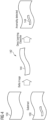
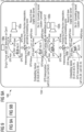
- Figure 2 shows, in the form of a flow chart, steps of a method 120 for monitoring of the race track 100.
- a step 121 at least one sequence of images is obtained from a camera capturing at least one section of the race track 100.
- a step 122 an images of the sequence of images is segmented into different areas 102, 104, 106, and 108 associated with the race track 100. Segmentation may be performed based on a manually segmentation mask provided before the race starts, or an automatically or semi-automatically generated segmentation mask computed during initialisation, upon camera movements or in real-time.
- a step 123 at least one vehicle 110 is detected in the sequence of images using automatic object recognition. The order of steps 122 and 123 may also be reverted, i.e. potentially moving objects may be detected first and used in aiding image segmentation process.
- a step 124 the at least one detected vehicle 110 is mapped to at least one of the different areas 102, 104, 106 or 108 associated with the race track 100.
- a decision step 125 it is determined whether at least one rule from a set of rules is triggered.
- the set of rules comprises at least one first rule triggering a first warning if the at least one detected vehicle 110 is mapped to a first predefined area of the race track 100, e.g. a crash barrier 108. If not, the method continues in step 121 with obtaining and processing the next image. However, if in step 125 at least one rule from the set of rules is triggered, at least one warning device is activated in a step 126 based on the set of rules.
- this may comprises a plurality of predefined, individual rules for triggering a warning.
- Each rule may comprise one or more conditions, determining when the rule is triggered, and one or more actions that are performed when the rule is triggered.
- the set of rules may comprise the following rules: Condition Action Object person detected on segment driving surface. Light red signal on trackside panel. Object vehicle detected on segment gravel area. Light yellow signal on trackside panel. Object oil spill detected on segment driving surface. Light red signal on trackside panel. Object vehicle detected on segment crash barrier. Display live camera signal on control monitor of race marshal.
- the detection of anomalies may be triggered whenever a vehicle 110 enters a monitored section 130 of the track 100. Thereafter, a differential analysis of the race track 100 before and after the vehicle 110 has passed the relevant section 130 of the track 100 can be performed. Again this detection may be based on artificial intelligence and suitable training data. For example, the system may be trained with the above acceptable anomalies as well as inacceptable anomalies based on previous race events and manual tagging of acceptable and inacceptable deviations in the historic footage.
- anomalies may be artificially created, for example by placing a foreign object on the race track 100 and marking it as an inacceptable anomaly. To improve the detection rate, images of both acceptable and inacceptable anomalies should be taken in different weather conditions.
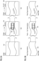
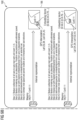
- a sequence of images 132, 134 and 136 shows the same section 130 of the race track 100 before, during and after passage of a vehicle 110 as detection by the object detection system. Processing may be triggered by the successful detection of a car or other vehicle 110 within the image 134 provided by a camera, and captured by a frame grabber. Once a vehicle 110 has been detected, the images 132 and 136 may be selected from the captured video material. For example, the last image in a time sequence of images taken before a bounding box 138 surrounding the detected vehicle 110 enters the section 130 may be selected as first image 132. Equally, the first image in the time sequence of images taken after the bounding box 138 surrounding the detected vehicle 110 leaves the section 130 may be selected as third image 136.
- Figure 3B shows the same sequence of images 132, 134 and 134 after segmentation.
- the used segmentation algorithm extracts only a single segment 140 corresponding to the driving surface 102 of the race track.
- the detected vehicle 110 is positioned within the segment 140, i.e. on the race track 100. Thus, no alarm is raised at this stage.
- a comparison between segments of interest may be performed.
- a delta image 142 between the segment 140 in the first image 132 and the same segment 140 in the third images 136 may be computed.
- the delta image 142 is classified using a deep learning classifier to decide whether the delta image corresponds to or comprises at least one known anomaly 144.
- a corresponding warning may be activated for all of the race track 100 or at least the section 130 comprising the anomaly 144.
- the warning may be triggered automatically by the monitoring system, i.e. without human intervention, or displayed to a race marshal or similar official for verification, with the option to either raise or suppress the warning.
- the positions of the vehicles 110 on the race track 100 may be determined and, optionally, tracked along the course.
- real-world positions for example GPS coordinates of reference points visible in the monitored section 130 of the tracks 100, may be recorded.
- detected objects such as vehicles 110 and anomalies 144 along the monitored section 130 of the track 100 can be related to the previously recorded position of reference points. That is to say, a reference point maps an image position defining a single pixel or a group of pixels, collectively referred to as pixel area, of a digital image of the race track 100 to a corresponding real-world position on the race track 100.
- reference points 150 are provided within another section 130 of the race track 100.
- the reference points 150 form a fixed grid of three times five reference points 150. This may be useful, for example, in case a position, direction and angle of a camera capturing the section 130 is fixed. In this case, during set-up or training, a GPS or similar position device with a visible marker may be placed at each reference point 150 in turn to determine its exact real-world position.
- the reference points 150 may coincide with prominent, high contrast features with in the section 130, i.e. edges or corners of segment boundaries, special objects like flagpoles or the like.
- Such reference points can be easily identified in a video image of the section 130, even if the camera moves, pans, or zooms in and out. Again, the real-world position of such prominent features is measured and stored during set-up or training, and used for triangulation during normal operation of the system.
- reference points 150 in their vicinity are used to estimate their current position.
- reference points 150i, 150j and 150o closest to a centre of a first bounding box 138a of the first vehicle 110a are used to estimate the present position of the first vehicle 110a by triangulation.
- reference points 150b, 150f and 150g closest to a centre of a second bounding box 138b of the second vehicle 110b are used to estimate the present position of the second vehicle 110b.
- the position of detected vehicles 110 and anomalies 144 can be displayed on a visual representation of the race track 100, e.g. at the race control, where race officials work and decide on track warnings and potential interruptions of a race.
- the described AI based monitoring system also enables some more advanced features, which are described below. In particular, it enables the re-identification of individual objects, e.g. a certain vehicle 110, on the race track.
- object detection or “object recognition” will be used to describe the mere detection of a certain type of object within a captured image, such as the presence of an arbitrary race car on a monitored section 130 of the race track 100.
- object re-identification will be used to describe the identification of a unique entity, such as a preregistered race car of an individual race participant currently on the track.
- the position of each vehicle 110 may be updated continuously, so as to create a so-called digital twin of the monitored vehicle 110 as shown, for example, in Figure 8 described later. In the described monitoring system, this is based on the re-identification of individual vehicles 110, rather than the mere detection of any vehicle 110 on the race track 100.
- Vehicles 110 may be distinguished based on extractable features, such as form, colour or other visible marks, such as logos or symbols printed on the vehicle 110.
- Suitable training data for the automatic identification may be captured at well-defined points of the race track 100. For example, images of an individual vehicle from different positions, e.g.
- the training images may also be taken by one or more cameras monitoring a first section 130 of the race track 100. Based on this information, whenever a vehicle 110 is detected along the race track 100, the detected object can be compared to the previously captured image data, for example by inferencing and computation of an embedding vector. Additional information may be used to improve the detection ratio, for example OCR of registration plates, in case registered vehicles 110 are racing on the race track 100.
- object re-identification is implemented using a neural network 160 that has been trained offline, i.e. before the use of the monitoring system in an actual race, using an encoder/decoder model to identify specific instances from a given class of objects, e.g. individual racing cars taking part in a currently running race.
- a given class of objects e.g. individual racing cars taking part in a currently running race.
- Different training sets may be used to train different instances of corresponding neural networks to different classes of objects, for example, Formula 1 cars, normal road cars, motorcycles or the like.
- training of the neural network 160 may be repeated.
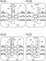
- the training of the neural network 160 used for object identification is conceptually shown in Figures 6A and 6C .
- images of different vehicles 110 are provided to an encoder or input side 162 of the neural network 160.
- a high number of training images is used, which are selected or confirmed manually and are taken on the actual race track 100.
- a set of about 17.000 vehicles extracted from archive footage of races on the Nürburgring was used to train the neural network 160 after a review of the material by a human.
- information received on the input side is simplified by nodes 164 of the neural network 160 to form or encode an embedding vector 166.
- the information of the embedding vector 166 is decoded to recreate an image on a decoder or output side 168 of the neural network 160.
- Weights and other settings of the neural network 160 are varied until the images on the output side 168 resemble the images provided to the input side 162 to a high degree, e.g. until a difference between becomes very small or minimal.
- the neural network has learned the characteristic features of vehicles 110 or a particular subclass of vehicles 110, such as racing cars. Comparison of the input side 162 and output side 168 can be performed automatically using an appropriate similarity metric.
- training of the neural network 160 may be performed unsupervised.
- the embedding vector 166 has only a single node 164, corresponding to a single dimension of information, e.g. the shape of an object.
- Figure 6C show another neural network 160 during training, with two nodes 164 forming the embedding vector 166, corresponding for example to a shape and a colour of the object of interest.
- a multi-dimensional embedding vector 166 in a multi-dimensional feature space 170 having for example 168 independent dimensions is used in the described system.
- the most significant properties for re-identification of specific vehicles 110 corresponding to each one of the nodes 164 representing a dimension of the embedding vector 166 are determined automatically by the training algorithm. Thus, they may not correspond to high-level properties such as colour or shape, and may not be easily comprehensible by humans.
- the neural network 160 can be used to extract or infer the characteristic properties of previously unknown vehicles 110 online, e.g. in real-time during a race.
- This process is shown in Figures 6B and 6D showing the classification of input images to determine a shape, or a shape and a colour of a vehicle 110. This inference is used for object re-identification during track monitoring.
- a vehicle 110 Before a vehicle 110 enters the race track 100, one or more images of the vehicle 110 are taken and processed by the previously trained neural network 160 to generate one or more corresponding embedding vectors 166.
- a first vehicle 110a may correspond to a first embedding vector 172
- a second vehicle 110b may correspond to a second embedding vector 174 in a multi-dimensional feature space 170.
- multiple images from different perspectives of the same vehicle 110 e.g. from the front, back and side, are used to create an array of possible embedding vectors, as described later.
- parts of an image corresponding to a detected vehicle 110 can be feed to the neural network to determine a new embedding vector 176.
- the new embedding vector 176 may then be compared with the previously registered vectors 172 and 174.
- the vehicle may then be identified as the vehicle corresponding to the closest previously known embedding vector, e.g. the first vehicle 110a corresponding to the first vector 172.
- an angle between the new embedding vector and all pre-registered embedding vectors 172 and 174 is computed and the vector with the smallest angle, e.g. the first embedding vector 172, is selected as best matching vector.
- the new vector may be stored in the system in an array of vectors 178 corresponding to a given vehicle 110. This may be used to improve future object identification, e.g. by adding embedding vectors 176 corresponding to an image of the same vehicle 110 taken from a different angle or under different environmental conditions, such as lighting or weather conditions. In the described system, up to 500 different embedding vectors can be stored for each registered vehicles. In general, this will make vehicle detection more likely and reliable.
- the identification may fail and/or the new embedding vector 176 is not included in the array of vectors 130. This may be used to exclude uncertain matches and/or to avoid degradation of the array of vectors 178.
- the above vehicle detection and identification can be further improved if the entire track 100 is covered by video cameras. In this case, continuous tracking of each moving object will enable its detection even if some or all of its characteristics features are temporarily blocked. In case not all parts of the race track 100 are covered by respective cameras and/or if movable cameras are used and do not cover a vehicle 110 of interest at any given moment, based on a digital model of the race track 100, certain logical assumptions about the likelihood of a vehicle 110 appearing in a certain area of the race track 100 may be used to improve the detection precision.
- FIG 8 shows a specific setup and operation of a monitoring system 180.
- the system 180 comprises a camera 182 capturing a corresponding section 130 of the race track 100.
- the system 180 further comprises an inferencing server 184 and a digital twin server 186.
- the inferencing server 184 capture digital images or video frames provided by the camera 182 and stores them for later use. At least a subset of the captures images are fed into an AI based object detection 188 unit to identify predetermined types of objects, such as vehicles 110. As shown in Figure 8 , each identified object is surrounded by a corresponding bounding box 138.
- the detection unit 188 also performs segmentation of the received camera images.
- the image of the track section 130 may be subdivide into areas corresponding to a driving surface 102, a grassy area 104 and a gravel area 106, respectively.
- the inferencing server 184 further comprises an inferencing unit 190.
- the inferencing unit 190 is setup to determine the position of the detected vehicles based on GPS position interpolation using known reference points 150 within the section 130.
- the inferencing unit 190 is further setup to generate an embedding vector for each detected vehicle 110 using the neural network 160.
- the determined embedding vector, together with a real-world position of the detected vehicle 110 on the race track 100 and/or an identifier of the camera, which captured the image, is passed to the digital twin server 186 for identification.
- the digital twin server may use multiple plausibility checks to identify each of the vehicles 110a and 110b.
- the set of embedding vectors used for matching can be restricted to those vehicles 110 known to be on the track 100.
- it may only select a subset of vehicles 110 likely to be in view of that camera. This can be achieved, for example, by only considering vehicles that have already passed another camera located on an earlier section of the race track 100.
- the subset of vehicles used in the identification process may be limited to vehicles that were last identified successfully in one of two or three sections of the track covered by other cameras. Including more than one up-track camera addresses the fact that some vehicles 110 may be covered in certain camera settings, or may not be identified successfully due to difficult light conditions or camera angles.
- the selection may be refined based on the real-world positions provided by the inferencing server 184. For example, based on an estimated speed of a vehicle 110 in the digital model, only those vehicles which could have plausibly reached a certain real-world position within a captured image at the time the image was taken may be considered for matching.
- Reduction of the number of vehicles 110 used during identification to a predetermined subset reduces the required processing power, and may thereby enable real-time identification with a relatively high resolution of input images during racing at high speeds.
- the higher resolution and reduction of plausible matches also improves detection precision. For example, in cases where two very similar vehicles, e.g. of the same model and colour, are taking part in the same race, but are located on different sections 140 of the race track 100, object identification is greatly improved compared with general real-time identification engines.
- the digital twin server selects the embedding vector that comes closets, in the multi-dimensional feature space 170, to the new embedding vector 176 provided by the inferring server 184 (see Figure 7 ) to identify the first vehicle 110a as a racing car with a given identifier, i.e. CarID 11, and the second vehicle 110b as another racing car with a given identifier, i.e. CarID 34.
- Figure 9 shows another configuration of the detection system 180, comprising two cameras 182a and 182b, corresponding to two different track sections 130a and 130b. For each location, essentially the same steps as those detailed above with respect to Figure 8 are performed. Details are not repeated here.
- an array of vectors 178 used to represent the identified car is updated as described before with reference to Figure 7 .
- the new embedding vector 176 is added to the array 178, if it differs significantly from all vectors in the array.
- another embedding vector may be deleted from the array, e.g. a vector quite similar to another vector of the array, or a vector lying entirely within the vector space defined by other vectors of the array 178.
- the information passed from the inference server 184 is then used to update a digital twin of the respective vehicles.
- its last known location, speed, position in the race order, etc. may be updated based on the renewed identification of the vehicle at its new, present location.
- all positions, estimated speeds, and other relevant information are stored persistently together with a time-stamp corresponding to the moment in time when a corresponding digital image was taken. In this way, the estimated position and speed of the vehicles can be shown live in the digital model.
- a race can be reconstructed with the digital model, e.g. for race analysis, identification of drivers responsible for accidents or the anomalies 144 along the race track 100.
- video sequences can be selected and cut automatically and be provided to the interested party.
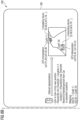
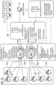
- Figure 10 shows a potential architecture to implement the above functionality. However, as detailed above, each of the described functions can be implemented and used individually, if desired.
- the monitoring system 180 of Figure 10 comprises two camera clusters 202a and 202b of four cameras 182a to 182d each.
- the cameras of each camera cluster 202 are connected to a corresponding rack workstation 204a and 204b, comprising one or more frame grabbing cards 206.
- the rack workstation 204 are responsible for grabbing essentially all video output of the respective camera cluster 202.
- the video footage is stored for three days for analysis and post-processing as detailed below.
- the rack workstation 204 perform further, different tasks during race monitoring and at other times, when no race currently takes place.
- the rack workstation 204 perform anomaly detection based on image segmentation, delta image computation and anomaly classification as detailed above. Moreover, the also perform vehicle tracking based on vehicle detection, vehicle embedding, image segmentation and location estimation as detailed above.
- the perform computationally expensive tasks such as batch processing for video generation, cutting of video footages for individual vehicles or drivers, and pixelisation of other vehicles or their registration numbers, e.g. for data protection.
- a digital twin processing unit 208 maps the inference and other information provided by the rack workstation 204 to a corresponding digital twin of the race track 100 and/or each individual vehicle 110. In particular, it keeps track of a speed estimation and current position of each vehicle 110. It further records the position, time and corresponding images of any detected incident, in particular crash of any vehicle 110. The digital twin processing unit 208 further monitors a state of the race track 100 and the positions of the vehicles 110 on the track.
- digital twin processing unit 208 also executes a rule engine.
- the rule engine generates alerts corresponding to detected incidents, such as vehicles crashes, and may control flags, display and other notifications along the track. Further vehicle information may be provided from the digital twin to the rule engine. This enables to formulate rules based on dynamic properties of the monitored system. For example, a rule may be triggered if a calculated speed of a vehicle lies below or above a certain threshold.
- the monitored track state and car positions are provided from the digital twin processing unit 208 to a track and car monitoring unit 210, e.g. for the benefit of race marshals or as information for the audience.
- a system monitoring unit 212 is provided to control and review the operation of the monitoring system 180 itself. It may show operational state of the software and hardware components of the monitoring system.
- a video postproduction unit 214 is provided, which is configured to gather all or selective footage from all the cameras 182, built target footage, e.g. of a specific vehicle 110 or vehicle group, e.g. the vehicles leading the race or involved in a particular incident, control video postproduction. It may also provide a customer API or web interface, allowing registered users to request and retrieve video material relevant to their own vehicle 110.
- the described monitoring system is more flexible, as both the training data as well as the rules set for detection, classifying and triggering can be continuously updated. Moreover, it does not require the installation of specific hardware, such as RFID based transponders as used in professional races, on or in the vehicles taking part in a race. Accordingly, the described monitoring system is particularly useful for amateur races with private vehicles, rather than professional races.
Landscapes
- Engineering & Computer Science (AREA)
- Theoretical Computer Science (AREA)
- Physics & Mathematics (AREA)
- General Physics & Mathematics (AREA)
- Multimedia (AREA)
- Computer Vision & Pattern Recognition (AREA)
- Evolutionary Computation (AREA)
- Artificial Intelligence (AREA)
- Health & Medical Sciences (AREA)
- Computing Systems (AREA)
- Databases & Information Systems (AREA)
- General Health & Medical Sciences (AREA)
- Medical Informatics (AREA)
- Software Systems (AREA)
- Quality & Reliability (AREA)
- Image Analysis (AREA)
- Traffic Control Systems (AREA)
- Closed-Circuit Television Systems (AREA)
- Train Traffic Observation, Control, And Security (AREA)
Applications Claiming Priority (2)
| Application Number | Priority Date | Filing Date | Title |
|---|---|---|---|
| EP21183397 | 2021-07-02 | ||
| EP21206396.0A EP4113459B1 (de) | 2021-07-02 | 2021-11-04 | Ki-basierte überwachung von rennbahnen |
Related Parent Applications (2)
| Application Number | Title | Priority Date | Filing Date |
|---|---|---|---|
| EP21206396.0A Division EP4113459B1 (de) | 2021-07-02 | 2021-11-04 | Ki-basierte überwachung von rennbahnen |
| EP21206396.0A Division-Into EP4113459B1 (de) | 2021-07-02 | 2021-11-04 | Ki-basierte überwachung von rennbahnen |
Publications (3)
| Publication Number | Publication Date |
|---|---|
| EP4459563A2 true EP4459563A2 (de) | 2024-11-06 |
| EP4459563A3 EP4459563A3 (de) | 2025-01-22 |
| EP4459563B1 EP4459563B1 (de) | 2026-07-08 |
Family
ID=82493873
Family Applications (1)
| Application Number | Title | Priority Date | Filing Date |
|---|---|---|---|
| EP24199783.2A Active EP4459563B1 (de) | 2021-07-02 | 2021-11-04 | Ki-basierte überwachung von rennstrecken |
Country Status (4)
| Country | Link |
|---|---|
| US (1) | US20250131729A1 (de) |
| EP (1) | EP4459563B1 (de) |
| JP (2) | JP7528356B2 (de) |
| WO (1) | WO2023274955A1 (de) |
Cited By (1)
| Publication number | Priority date | Publication date | Assignee | Title |
|---|---|---|---|---|
| US20230204373A1 (en) * | 2021-12-29 | 2023-06-29 | Hyundai Motor Company | Circuit driving guide device and method thereof |
Families Citing this family (8)
| Publication number | Priority date | Publication date | Assignee | Title |
|---|---|---|---|---|
| US12547796B2 (en) * | 2022-02-28 | 2026-02-10 | Inlecom Group BV | Critical infrastructure blueprint selection for optimized response to state changing conditions |
| US20240247948A1 (en) * | 2023-01-19 | 2024-07-25 | Leading Lights, Llc | Cloud-based system for controlling position indicators |
| KR20240156468A (ko) * | 2023-04-20 | 2024-10-30 | 현대자동차주식회사 | 서킷 모드를 수행하는 차량의 시스템 제한 제어 방법 |
| JP7473730B1 (ja) | 2023-09-22 | 2024-04-23 | Kddi株式会社 | 情報処理装置、情報処理方法及びプログラム |
| US20250390527A1 (en) * | 2024-06-20 | 2025-12-25 | Mediatek Inc. | Communication problem identification device and method |
| CN119697489B (zh) * | 2025-02-25 | 2025-04-18 | 深圳大学 | 一种速度轮滑运动轨迹跟踪与视频采集方法及装置 |
| CN120416521A (zh) * | 2025-04-18 | 2025-08-01 | 山东广电信通网络运营有限公司 | 一种公路自行车赛转播系统 |
| CN120954241A (zh) * | 2025-10-20 | 2025-11-14 | 河北交投智能科技股份有限公司 | 基于视频巡检与爆闪警示联动的智能交通预警系统及方法 |
Citations (2)
| Publication number | Priority date | Publication date | Assignee | Title |
|---|---|---|---|---|
| US6020851A (en) | 1997-10-06 | 2000-02-01 | Busack; Andrew J. | Auto race monitoring system |
| WO2017212232A1 (en) | 2016-06-06 | 2017-12-14 | Christopher Taylor | Track monitoring apparatus and system |
Family Cites Families (11)
| Publication number | Priority date | Publication date | Assignee | Title |
|---|---|---|---|---|
| US6760061B1 (en) * | 1997-04-14 | 2004-07-06 | Nestor Traffic Systems, Inc. | Traffic sensor |
| DE102013101639A1 (de) * | 2013-02-19 | 2014-09-04 | Continental Teves Ag & Co. Ohg | Verfahren und Vorrichtung zur Bestimmung eines Fahrbahnzustands |
| US9384423B2 (en) * | 2013-05-28 | 2016-07-05 | Xerox Corporation | System and method for OCR output verification |
| US11301685B2 (en) * | 2015-04-02 | 2022-04-12 | Sportsmedia Technology Corporation | Automatic determination and monitoring of vehicles on a racetrack with corresponding imagery data for broadcast |
| WO2018134964A1 (ja) * | 2017-01-20 | 2018-07-26 | 楽天株式会社 | 画像検索システム、画像検索方法およびプログラム |
| JP2020109354A (ja) * | 2017-03-31 | 2020-07-16 | 本田技研工業株式会社 | 動態管理システム、動態管理方法及びプログラム |
| JP7125843B2 (ja) * | 2018-01-12 | 2022-08-25 | 株式会社日立国際電気 | 障害検知システム |
| WO2019143722A1 (en) * | 2018-01-18 | 2019-07-25 | GumGum, Inc. | Augmenting detected regions in image or video data |
| CN110197097B (zh) * | 2018-02-24 | 2024-04-19 | 北京图森智途科技有限公司 | 一种港区监控方法及系统、中控系统 |
| CN110538455B (zh) * | 2019-09-05 | 2021-03-19 | 腾讯科技(深圳)有限公司 | 虚拟对象的移动控制方法、装置、终端及存储介质 |
| CN111723768B (zh) * | 2020-06-30 | 2023-08-11 | 北京百度网讯科技有限公司 | 车辆重识别的方法、装置、设备和存储介质 |
-
2021
- 2021-11-04 EP EP24199783.2A patent/EP4459563B1/de active Active
-
2022
- 2022-06-27 US US18/015,609 patent/US20250131729A1/en active Pending
- 2022-06-27 WO PCT/EP2022/067557 patent/WO2023274955A1/en not_active Ceased
- 2022-06-27 JP JP2023503059A patent/JP7528356B2/ja active Active
-
2024
- 2024-07-24 JP JP2024118361A patent/JP7834809B2/ja active Active
Patent Citations (2)
| Publication number | Priority date | Publication date | Assignee | Title |
|---|---|---|---|---|
| US6020851A (en) | 1997-10-06 | 2000-02-01 | Busack; Andrew J. | Auto race monitoring system |
| WO2017212232A1 (en) | 2016-06-06 | 2017-12-14 | Christopher Taylor | Track monitoring apparatus and system |
Cited By (2)
| Publication number | Priority date | Publication date | Assignee | Title |
|---|---|---|---|---|
| US20230204373A1 (en) * | 2021-12-29 | 2023-06-29 | Hyundai Motor Company | Circuit driving guide device and method thereof |
| US12345541B2 (en) * | 2021-12-29 | 2025-07-01 | Hyundai Motor Company | Circuit driving guide device and method thereof |
Also Published As
| Publication number | Publication date |
|---|---|
| JP7834809B2 (ja) | 2026-03-24 |
| US20250131729A1 (en) | 2025-04-24 |
| EP4459563B1 (de) | 2026-07-08 |
| JP2024156219A (ja) | 2024-11-01 |
| JP2023536692A (ja) | 2023-08-29 |
| WO2023274955A1 (en) | 2023-01-05 |
| JP7528356B2 (ja) | 2024-08-05 |
| EP4459563A3 (de) | 2025-01-22 |
Similar Documents
| Publication | Publication Date | Title |
|---|---|---|
| US20250131729A1 (en) | Ai based monitoring of race tracks | |
| CN108062349B (zh) | 基于视频结构化数据及深度学习的视频监控方法和系统 | |
| KR102282800B1 (ko) | 라이다와 영상카메라를 이용한 멀티 표적 추적 방법 | |
| CN113676702B (zh) | 基于视频流的目标追踪监测方法、系统、装置及存储介质 | |
| CN112435276B (zh) | 一种车辆跟踪方法、装置、智能终端及存储介质 | |
| US8301577B2 (en) | Intelligent monitoring system for establishing reliable background information in a complex image environment | |
| KR101735365B1 (ko) | 학습 기반의 영상 내 관심 물체 검지 및 환경 변화에 강인한 물체 추적 방법 | |
| KR102360568B1 (ko) | 터널 내 돌발상황 감지 시스템 및 방법 | |
| Chang et al. | Video analytics in smart transportation for the AIC’18 challenge | |
| Bloisi et al. | Argos—A video surveillance system for boat traffic monitoring in Venice | |
| KR101472674B1 (ko) | 군중 궤적 추출을 이용한 비정상 행동 검출에 기초한 영상 감시 방법 및 영상 감시 장치 | |
| CN112084892B (zh) | 一种道路异常事件检测管理装置及其方法 | |
| EP4113459B1 (de) | Ki-basierte überwachung von rennbahnen | |
| CN113484858A (zh) | 一种入侵检测方法和系统 | |
| US11176379B2 (en) | Method of acquiring detection zone in image and method of determining zone usage | |
| CN112329691A (zh) | 一种监控视频的分析方法及装置、电子设备、存储介质 | |
| CN116403179B (zh) | 基于雷视多源数据深度融合的车辆全息感知及风险行为识别系统 | |
| CN113011371A (zh) | 目标检测方法、装置、设备及存储介质 | |
| CN117746649A (zh) | 一种基于YOLOv8算法的隧道车流量检测系统及方法 | |
| CN108830204B (zh) | 面对目标的监控视频中异常检测方法 | |
| KR20210133827A (ko) | 딥러닝 모델을 학습시키기 위한 장치 및 그 방법 | |
| CN112257683A (zh) | 一种面向车辆运行轨迹监测的跨镜追踪方法 | |
| US20090042628A1 (en) | Horse position information analyzing and displaying method | |
| CN116152496B (zh) | 一种基于帧差法和语义分割结合的道路抛洒物识别方法 | |
| CN117496446B (zh) | 一种基于目标检测和级联匹配的人流量统计方法 |
Legal Events
| Date | Code | Title | Description |
|---|---|---|---|
| PUAI | Public reference made under article 153(3) epc to a published international application that has entered the european phase |
Free format text: ORIGINAL CODE: 0009012 |
|
| STAA | Information on the status of an ep patent application or granted ep patent |
Free format text: STATUS: THE APPLICATION HAS BEEN PUBLISHED |
|
| AC | Divisional application: reference to earlier application |
Ref document number: 4113459 Country of ref document: EP Kind code of ref document: P |
|
| AK | Designated contracting states |
Kind code of ref document: A2 Designated state(s): AL AT BE BG CH CY CZ DE DK EE ES FI FR GB GR HR HU IE IS IT LI LT LU LV MC MK MT NL NO PL PT RO RS SE SI SK SM TR |
|
| REG | Reference to a national code |
Ref country code: DE Free format text: PREVIOUS MAIN CLASS: G06V0010200000 Ipc: G06V0020540000 Ref country code: DE Ref legal event code: R079 Ref document number: 602021057107 Country of ref document: DE Free format text: PREVIOUS MAIN CLASS: G06V0010200000 Ipc: G06V0020540000 |
|
| PUAL | Search report despatched |
Free format text: ORIGINAL CODE: 0009013 |
|
| AK | Designated contracting states |
Kind code of ref document: A3 Designated state(s): AL AT BE BG CH CY CZ DE DK EE ES FI FR GB GR HR HU IE IS IT LI LT LU LV MC MK MT NL NO PL PT RO RS SE SI SK SM TR |
|
| RIC1 | Information provided on ipc code assigned before grant |
Ipc: G06V 10/82 20220101ALI20241218BHEP Ipc: G06V 10/20 20220101ALI20241218BHEP Ipc: G06V 10/26 20220101ALI20241218BHEP Ipc: G06V 10/62 20220101ALI20241218BHEP Ipc: G06V 20/50 20220101ALI20241218BHEP Ipc: G06V 20/54 20220101AFI20241218BHEP |
|
| RAP3 | Party data changed (applicant data changed or rights of an application transferred) |
Owner name: FSAS TECHNOLOGIES GMBH |
|
| STAA | Information on the status of an ep patent application or granted ep patent |
Free format text: STATUS: REQUEST FOR EXAMINATION WAS MADE |
|
| 17P | Request for examination filed |
Effective date: 20250722 |
|
| RAP1 | Party data changed (applicant data changed or rights of an application transferred) |
Owner name: FUJITSU GERMANY GMBH |
|
| GRAP | Despatch of communication of intention to grant a patent |
Free format text: ORIGINAL CODE: EPIDOSNIGR1 |
|
| STAA | Information on the status of an ep patent application or granted ep patent |
Free format text: STATUS: GRANT OF PATENT IS INTENDED |
|
| RIC1 | Information provided on ipc code assigned before grant |
Ipc: G06V 20/54 20220101AFI20260227BHEP Ipc: G06V 10/764 20220101ALI20260227BHEP Ipc: G06V 10/20 20220101ALI20260227BHEP Ipc: G06V 10/26 20220101ALI20260227BHEP Ipc: G06V 10/62 20220101ALI20260227BHEP Ipc: G06V 10/82 20220101ALI20260227BHEP |
|
| INTG | Intention to grant announced |
Effective date: 20260313 |
|
| GRAS | Grant fee paid |
Free format text: ORIGINAL CODE: EPIDOSNIGR3 |
|
| GRAA | (expected) grant |
Free format text: ORIGINAL CODE: 0009210 |
|
| STAA | Information on the status of an ep patent application or granted ep patent |
Free format text: STATUS: THE PATENT HAS BEEN GRANTED |
|
| AC | Divisional application: reference to earlier application |
Ref document number: 4113459 Country of ref document: EP Kind code of ref document: P |
|
| AK | Designated contracting states |
Kind code of ref document: B1 Designated state(s): AL AT BE BG CH CY CZ DE DK EE ES FI FR GB GR HR HU IE IS IT LI LT LU LV MC MK MT NL NO PL PT RO RS SE SI SK SM TR |
|
| REG | Reference to a national code |
Ref country code: CH Ref legal event code: F10 Free format text: ST27 STATUS EVENT CODE: U-0-0-F10-F00 (AS PROVIDED BY THE NATIONAL OFFICE) Effective date: 20260708 Ref country code: GB Ref legal event code: FG4D |
|
| REG | Reference to a national code |
Ref country code: IE Ref legal event code: FG4D |
|
| REG | Reference to a national code |
Ref country code: DE Ref legal event code: R096 Ref document number: 602021057107 Country of ref document: DE |