EP4459352A2 - Optisches system, kameramodul und elektronische vorrichtung - Google Patents
Optisches system, kameramodul und elektronische vorrichtung Download PDFInfo
- Publication number
- EP4459352A2 EP4459352A2 EP24201333.2A EP24201333A EP4459352A2 EP 4459352 A2 EP4459352 A2 EP 4459352A2 EP 24201333 A EP24201333 A EP 24201333A EP 4459352 A2 EP4459352 A2 EP 4459352A2
- Authority
- EP
- European Patent Office
- Prior art keywords
- lens
- optical system
- optical axis
- object side
- image side
- Prior art date
- Legal status (The legal status is an assumption and is not a legal conclusion. Google has not performed a legal analysis and makes no representation as to the accuracy of the status listed.)
- Pending
Links
Images


Classifications
-
- G—PHYSICS
- G02—OPTICS
- G02B—OPTICAL ELEMENTS, SYSTEMS OR APPARATUS
- G02B13/00—Optical objectives specially designed for the purposes specified below
- G02B13/001—Miniaturised objectives for electronic devices, e.g. portable telephones, webcams, PDAs, small digital cameras
- G02B13/0015—Miniaturised objectives for electronic devices, e.g. portable telephones, webcams, PDAs, small digital cameras characterised by the lens design
- G02B13/002—Miniaturised objectives for electronic devices, e.g. portable telephones, webcams, PDAs, small digital cameras characterised by the lens design having at least one aspherical surface
- G02B13/0045—Miniaturised objectives for electronic devices, e.g. portable telephones, webcams, PDAs, small digital cameras characterised by the lens design having at least one aspherical surface having five or more lenses
-
- G—PHYSICS
- G02—OPTICS
- G02B—OPTICAL ELEMENTS, SYSTEMS OR APPARATUS
- G02B13/00—Optical objectives specially designed for the purposes specified below
- G02B13/001—Miniaturised objectives for electronic devices, e.g. portable telephones, webcams, PDAs, small digital cameras
- G02B13/0055—Miniaturised objectives for electronic devices, e.g. portable telephones, webcams, PDAs, small digital cameras employing a special optical element
-
- G—PHYSICS
- G02—OPTICS
- G02B—OPTICAL ELEMENTS, SYSTEMS OR APPARATUS
- G02B9/00—Optical objectives characterised both by the number of the components and their arrangements according to their sign, i.e. + or -
- G02B9/62—Optical objectives characterised both by the number of the components and their arrangements according to their sign, i.e. + or - having six components only
Definitions
- the subject matter relates to field of optical imaging, and more particularly, to an optical system, a camera module, and an electronic device.
- An object of the present application is to provide an optical system, a camera module, and an electronic device, the optical system satisfies the requirements of large aperture, miniaturization, and good imaging effect.
- the present application provides an optical system.
- the optical system consists of six lenses having refractive power. From an object side to an image side along an optical axis, the six lenses sequentially include a first lens, a second lens, a third lens, a fourth lens, a fifth lens, and a sixth lens.
- the first lens has positive refractive power, and an object side surface and an image side surface of the first lens are convex near the optical axis.
- the second lens has negative refractive power, and an image side surface of the second lens is concave near the optical axis.
- the third lens has refractive power, an object side surface of the third lens is convex near the optical axis, and an image side surface of the third lens is concave near the optical axis.
- the fourth lens has negative refractive power, an object side surface of the fourth lens is concave near the optical axis, and an image side surface of the fourth lens is convex near the optical axis.
- the fifth lens has positive refractive power, and an object side surface of the fifth lens is convex near the optical lens.
- the sixth lens has negative refractive power, an object side surface of the sixth lens is convex near the optical axis, and an image side surface of the sixth lens is concave near the optical axis.
- the optical system satisfies the relational expression: 1.9 ⁇ FNO ⁇ 2.3, 85deg ⁇ FOV ⁇ 100deg, 1.1 ⁇ TTL/ImgH ⁇ 1.4, wherein, FNO is an aperture number of the optical system, FOV is a maximum field of view of the optical system, and ImgH is half of an image height corresponding to a maximum field of view of the optical system.
- the first lens has positive refractive power, and the object side surface and image side surface of the first lens are both convex near the optical axis, which is favorable for shortening a total optical length of the optical system, compressing light direction of respective field of view, and reducing spherical aberration, thereby satisfying requirements of high image quality and small size of the optical system. It is also beneficial for improving the positive refractive power of the first lens so as to further provide a reasonable incident angle of light to guide the edge light.
- the second lens has negative refractive power, and the image side surface of the second lens is concave near the near optical axis, which is conducive to entry and deflection of the edge light and can reduce a desired deflection angle of the rear lens, thereby allowing the deflection angle of light on each lens to be more uniform, and effectively correcting the aberration of the edge field of view.
- the third lens has refractive power, the object side surface of the third lens is convex near the optical axis, and the image side surface of the third lens is concave near the optical axis, which is favorable for delaying the light entering the system via the front lens and delaying the angle.
- the fourth lens has negative refractive power, the object side surface of the fourth lens is concave near the optical axis, and the image side surface of the fourth lens is convex near the optical axis, which is favorable for correcting the spherical aberration, coma, and distortion generated by the first lens, second lens, and third lens.
- the fifth lens has positive refractive power, and the object side surface of the fifth lens is convex near the optical axis, which is favorable for reasonably constraining curvature radius of the fifth lens, thereby reducing tolerance sensitivity of the optical system, and reducing the risk of generation of stray light.
- the sixth lens has negative refractive power, the object side surface of the sixth lens is convex near the optical axis, and the image side surface of the sixth lens is concave near the optical axis, which is favorable for shortening the total length of the optical system, correcting aberrations, increasing an emitting angle of light to allow the optical system to have the characteristics of a large image surface, and improving the resolution of the optical system, thereby allowing the optical system to have better imaging quality.
- the optical system may have the characteristics of a large aperture, and the optical system may have sufficient amount of incident light.
- the optical system may capture images with higher definition, and the optical system is suitable for photographing high quality images of low brightness space scenes such as night scenes and starry skies.
- the optical system may have a large field of view.
- the optical system may have the characteristics of high pixels and high definition.
- the optical system may have ultra-thin characteristics, meet a requirement of miniaturization of the optical system, and have more advantages when shooting scenes at medium focus distances.
- the present application further provides a camera module.
- the lens module includes a photosensitive chip and the optical system mentioned in any one of embodiments of the first aspect, and the photosensitive chip is located on an image side of the optical system.
- a photosensitive surface of the photosensitive chip is located on an imaging surface of the optical system.
- the light of an object that passes through the lens and is incident on the photosensitive surface can be converted into an electrical signal of an image.
- the photosensitive chip may be a complementary metal oxide semiconductor (CMOS) or a charge-coupled device (CCD).
- CMOS complementary metal oxide semiconductor
- CCD charge-coupled device
- the camera module can be an imaging module integrated in an electronic device or an independent lens.
- the present application further provides an electronic device.
- the electronic device includes a housing and the camera module mentioned in the second aspect, and the camera module is located in the housing.
- the electronic device includes but is not limited to an automobile, a monitor, a smart phone, a computer, and a smart watch.
- the present application provides an optical system.
- the optical system consists of six lenses having refractive power. From an object side to an image side along an optical axis, the six lenses sequentially include a first lens, a second lens, a third lens, a fourth lens, a fifth lens, and a sixth lens.
- the first lens has positive refractive power, and an object side surface and an image side surface of the first lens are convex near the optical axis.
- the second lens has negative refractive power, and an image side surface of the second lens is concave near the optical axis.
- the third lens has refractive power, an object side surface of the third lens is convex near the optical axis, and an image side surface of the third lens is concave near the optical axis.
- the fourth lens has negative refractive power, an object side surface of the fourth lens is concave near the optical axis, and an image side surface of the fourth lens is convex near the optical axis.
- the fifth lens has positive refractive power, and an object side surface of the fifth lens is convex near the optical lens.
- the sixth lens has negative refractive power, an object side surface of the sixth lens is convex near the optical axis, and an image side surface of the sixth lens is concave near the optical axis.
- optical system satisfies the relational expression: 1.9 ⁇ FNO ⁇ 2.3. Further, the optical system satisfies the relational expression: 2 ⁇ FNO ⁇ 2.2. Wherein, FNO is an aperture number of the optical system.
- optical system satisfies the relational expression: 85deg ⁇ FOV ⁇ 100deg. Further, the optical system satisfies the relational expression: 877deg ⁇ FOV ⁇ 95deg.
- FOV is a maximum field of view of the optical system.
- the optical system satisfies the relational expression: 1.1 ⁇ TTL/ImgH ⁇ 1.4. Further, the optical system satisfies the relational expression: 1.22 ⁇ TTL/ImgH ⁇ 1.35.
- ImgH is half of an image height corresponding to a maximum field of view of the optical system.
- the first lens has positive refractive power, and the object side surface and image side surface of the first lens are both convex near the optical axis, which is favorable for shortening a total optical length of the optical system, compressing light direction of respective field of view, and reducing spherical aberration, thereby satisfying requirements of high image quality and small size of the optical system. It is also beneficial for improving the positive refractive power of the first lens so as to further provide a reasonable incident angle of light to guide the edge light.
- the second lens has negative refractive power, and the image side surface of the second lens is concave near the near optical axis, which is conducive to entry and deflection of the edge light and may reduce a desired deflection angle of the rear lens, thereby allowing the deflection angle of light on each lens to be more uniform, and effectively correcting the aberration of the edge field of view.
- the third lens has refractive power, the object side surface of the third lens is convex near the optical axis, and the image side surface of the third lens is concave near the optical axis, which is favorable for delaying the light entering the system via the front lens and delaying the angle.
- the fourth lens has negative refractive power, the object side surface of the fourth lens is concave near the optical axis, and the image side surface of the fourth lens is convex near the optical axis, which is favorable for correcting the spherical aberration, coma, and distortion generated by the first lens, second lens, and third lens.
- the fifth lens has positive refractive power, and the object side surface of the fifth lens is convex near the optical axis, which is favorable for reasonably constraining curvature radius of the fifth lens, thereby reducing tolerance sensitivity of the optical system, and reducing the risk of generation of stray light.
- the sixth lens has negative refractive power, the object side surface of the sixth lens is convex near the optical axis, and the image side surface of the sixth lens is concave near the optical axis, which is favorable for shortening the total length of the optical system, correcting aberrations, increasing a light emitting to allow the optical system to have the characteristics of a large image surface, and improving the resolution of the optical system, thereby allowing the optical system to have better imaging quality.
- the optical system may have the characteristics of a large aperture, and the optical system may have sufficient amount of incident light.
- the optical system can capture images with higher definition, and the optical system is suitable for photographing high quality images of low brightness space scenes such as night scenes and starry skies.
- the optical system may have a large field of view.
- the optical system may have the characteristics of high pixels and high definition.
- the optical system may have ultra-thin characteristics, meet the requirement of miniaturization of the optical system, and have more advantages when shooting scenes at medium focus distances.
- the optical system satisfies the relational expression: 0.5 ⁇ R11/f ⁇ 1.1. Further, the optical system satisfies the relational expression: 0.6 ⁇ R11/f ⁇ 1.
- R11 is a radius of curvature of an object side surface of the first lens at the optical axis
- f is an effective focal length of the optical system.
- the optical system satisfies the relational expression: -1.1 ⁇ R12/f ⁇ -0.5. Further, the optical system satisfies the relational expression: -1 ⁇ R12/f ⁇ -0.6.
- R12 is a radius of curvature of an image side surface of the first lens at the optical axis
- f is the effective focal length of the optical system.
- a ratio of the curvature radius of the image side surface of the first lens at the optical axis and the effective focal length of the optical system may be reasonably limited, so that a surface shape of the object side surface of first lens and a surface shape of the image side surface of the first lens are matched to quickly converge the light, thereby reducing an aperture of a head of the optical system and realizing miniaturization of the head of the optical system.
- the optical system satisfies the relational expression: 5 ⁇
- R21 is the radius of curvature of the object side surface of the second lens at the optical axis
- f is the effective focal length of the optical system.
- the optical system satisfies the relational expression: 0.6 ⁇ R22/f ⁇ 1.3. Further, the optical system satisfies the relational expression: 0.77 ⁇ R22/f ⁇ 1.2.
- R22 is the radius of curvature of the image side surface of the second lens at the optical axis
- f is the effective focal length of the optical system.
- the optical system satisfies the relational expression: 0.5 ⁇ R31/f ⁇ 1.2. Further, the optical system satisfies the relational expression: 0.6 ⁇ R31/f ⁇ 1.1.
- R31 is a radius of curvature of an object side surface of the third lens at the optical axis
- f is the effective focal length of the optical system.
- the optical system satisfies the relational expression: 0.6 ⁇ R32/f ⁇ 1.2. Further, the optical system satisfies the relational expression: 0.7 ⁇ R32/f ⁇ 1.1.
- R32 is a radius of curvature of the image side surface of the third lens at the optical axis
- f is the effective focal length of the optical system.
- the optical system satisfies the relational expression: -1 ⁇ R41/f ⁇ -0.3. Further, the optical system satisfies the relational expression: -0.9 ⁇ R41/f ⁇ -0.35.
- R41 is a radius of curvature of the object side surface of the fourth lens at the optical axis
- f is the effective focal length of the optical system.
- the optical system satisfies the relational expression: -2.1 ⁇ R42/f ⁇ -0.4. Further, the optical system satisfies the relational expression: -1.9 ⁇ R42/f ⁇ -0.5.
- R42 is a radius of curvature of the image side surface of the fourth lens at the optical axis
- f is the effective focal length of the optical system.
- the optical system satisfies the relational expression: 0.2 ⁇ R51/f ⁇ 0.8. Further, the optical system satisfies the relational expression: 0.3 ⁇ R51/f ⁇ 0.7.
- R51 is a radius of curvature of the object side surface of the fifth lens at the optical axis
- f is the effective focal length of the optical system.
- the optical system satisfies the relationship: 2.5 ⁇
- R52 is the radius of curvature of the image side surface of the fifth lens at the optical axis
- f is the effective focal length of the optical system.
- the optical system satisfies the relational expression: 0.2 ⁇ R61/f ⁇ 0.7. Further, the optical system satisfies the relational expression: 0.3 ⁇ R61/f ⁇ 0.6.
- R61 is a radius of curvature of the object side surface of the sixth lens at the optical axis
- f is the effective focal length of the optical system.
- the optical system satisfies the relational expression: 0.1 ⁇ R62/f ⁇ 0.35. Further, the optical system satisfies the relational expression: 0.15 ⁇ R62/f ⁇ 0.35.
- R62 is a radius of curvature of the image side surface of the sixth lens at the optical axis
- f is the effective focal length of the optical system.
- the optical system satisfies the relational expression: 1 ⁇
- R32 is a radius of curvature of the image side surface of the third lens at the optical axis
- R41 is the radius of curvature of the object side surface of the fourth lens at the optical axis.
- the ratio of the radius of curvature of the image side surface of the third lens at the optical axis to the radius of curvature of the object side surface of the fourth lens at the optical axis may be reasonably limited, which may control the spacing change of a gap between the third lens and the fourth lens, reduce the sensitivity of the third lens and the fourth lens during the production process, and balance the spherical chromatic aberration of the optical system.
- the imaging quality of the optical system may be improved.
- the optical system satisfies the relational expression: 0.3 ⁇
- R61 is a radius of curvature of the object side surface of the sixth lens at the optical axis
- R62 is a radius of curvature of the image side surface of the sixth lens at the optical axis
- f6 is the effective focal length of the sixth lens.
- the ratio of the sum of the radii of curvature of the object side surface and the image side surface of the sixth lens at the optical axis to the effective focal length of the sixth lens may be reasonably limited, so that the astigmatism of the sixth lens is controlled within a reasonable range, effectively balancing the astigmatism generated by the first lens to the fifth lens, and improving the imaging quality of the optical system.
- the optical system satisfies the relational expression: 0.6 ⁇ f1/f ⁇ 0.9. Further, the optical system satisfies the relational expression: 0.65 ⁇ f1/f ⁇ 0.85.
- f1 is the effective focal length of the first lens
- f is the effective focal length of the optical system.
- the optical system satisfies the relational expression: -1.6 ⁇ f2/f ⁇ -1. Further, the optical system satisfies the relational expression: -1.5 ⁇ f2/f ⁇ -1.1.
- f2 is the effective focal length of the second lens
- f is the effective focal length of the optical system.
- the optical system satisfies the relational expression: 7 ⁇
- f3 is the effective focal length of the third lens
- f is the effective focal length of the optical system.
- the optical system satisfies the relational expression: -7 ⁇ f4/f ⁇ -1. Further, the optical system satisfies the relational expression: -7 ⁇ f4/f ⁇ -1.1.
- f4 is the effective focal length of the fourth lens
- f is the effective focal length of the optical system.
- the optical system satisfies the relational expression: 0.5 ⁇ f5/f ⁇ 1.2. Further, the optical system satisfies the relational expression: 0.6 ⁇ f5/f ⁇ 1.1.
- f5 is the effective focal length of the fifth lens
- f is the effective focal length of the optical system.
- the optical system satisfies the relational expression: -1.6 ⁇ f6/f ⁇ -1. Further, the optical system satisfies the relational expression: -1.5 ⁇ f6/f ⁇ -1.1.
- f6 is the effective focal length of the sixth lens
- f is the effective focal length of the optical system.
- the optical system satisfies the relational expression: 2 ⁇ FNO*tan(HFOV) ⁇ 2.4. Further, the optical system satisfies the relational expression: 2.1 ⁇ FNO*tan(HFOV) ⁇ 2.3.
- FNO is the aperture number of the optical system
- HFOV is half of the maximum field of view of the optical system.
- the optical system satisfies the relational expression: 3.8 ⁇ f/SD11 ⁇ 4.5. Further, the optical system satisfies the relational expression: 4 ⁇ f/SD11 ⁇ 4.3.
- f is the effective focal length of the optical system
- SD11 is the maximum effective aperture of the object side surface of the first lens.
- the amount of light entering the optical system may be improved, and a miniaturized design of the head of may be realized, so that the optical system may be more suitable for applications in under-screen cameras and low light scenes.
- the aperture of the first lens is too large, which is not conducive to miniaturization of the head.
- the amount of incident light is too small, and the image quality is poor under low light conditions.
- the optical system satisfies the relational expression: 1.1 ⁇ CT1/SD11 ⁇ 1.4. Further, the optical system satisfies the relational expression: 1.1 ⁇ CT1/SD11 ⁇ 1.3.
- CT1 is a thickness of the first lens at the optical axis
- SD11 is the maximum effective aperture of the object side surface of the first lens.
- the optical system satisfies the relational expression: 0.6 ⁇ ET1/CT1 ⁇ 0.9. Further, the optical system satisfies the relational expression: 0.65 ⁇ ETl/CTl ⁇ 0.8.
- ET1 is a distance from a position where the object side surface of the first lens has the maximum effective aperture to a position where the image side surface of the first lens has the maximum effective aperture along the optical axis
- CT1 is a thickness of the first lens at the optical axis.
- the first lens is a convex lens with a thick center and thin sides, and has positive refractive power, which may allow the first lens to shrink the incident light, thereby reducing the total optical length.
- the first lens may have a large edge thickness, which may allow the optical system to achieve a deeper head structure while meeting the requirements of a small head structure, so that the optical system may be suitable for shooting scenes with holes, such as full screen screens and under-screen cameras.
- the edge thickness of the first lens may small, and the depth of the head structure of the optical system may small, which cannot meet specific requirements of head depth.
- the refractive power of the first lens may be relatively small, making which cannot provide good deflection conditions for incident light and is not conducive to the contraction of light.
- the optical system satisfies the relational expression: 1 ⁇ CT5/ET5 ⁇ 1.8. Further, the optical system satisfies the relational expression: 1.1 ⁇ CT5/ET5 ⁇ 1.65.
- CT5 is a thickness of the fifth lens at the optical axis
- ET5 is a distance from a position where the object side surface of the fifth lens has the maximum effective aperture to a position where the image side surface of the fifth lens has the maximum effective aperture along the optical axis.
- the edge thickness and center thickness of the fifth lens may be reasonably limited, the shape of the fifth lens may be controlled, and the spherical aberration, chromatic aberration, and field curvature of the optical system may be comprehensively balanced, and the imaging quality of the optical system may be improved.
- the optical system satisfies the relational expression: 0.8 ⁇ ET6/CT6 ⁇ 1.3. Further, the optical system satisfies the relational expression: 0.85 ⁇ ET6/CT6 ⁇ 1.2.
- ET6 is a distance from a position where the object side surface of the sixth lens has the maximum effective aperture to a position where the image side surface of the sixth lens has the maximum effective aperture along the optical axis
- CT6 is a thickness of the sixth lens at the optical axis.
- the proportion of edge thickness of the sixth lens may be small, and the supporting part is difficult to meet the thickness standard.
- the thickness of the sixth lens may be too large, which may cause the external support part to occupy too much space.
- the optical system satisfies the relational expression: 1 ⁇ CT5/CT6 ⁇ 1.8.
- the optical system satisfies the relational expression: 1 ⁇ CT5/CT6 ⁇ 1.7.
- CT5 is a thickness of the fifth lens at the optical axis
- CT6 is a thickness of the sixth lens at the optical axis.
- the optical system satisfies the relational expression: 3 ⁇ TD/CT1 ⁇ 4. Further, the optical system satisfies the relational expression: 3.3 ⁇ TD/CT1 ⁇ 3.9.
- TD is a distance from the object side surface of the first lens to the image side surface of the sixth lens along the optical axis
- CT1 is a thickness of the first lens at the optical axis.
- the optical system satisfies the relational expression: 0.5 ⁇ AT56/AT23 ⁇ 1.8.
- the optical system satisfies the relational expression: 0.6 ⁇ AT56/AT23 ⁇ 1.7.
- AT56 is a distance from the image side surface of the fifth lens to the object side surface of the sixth lens along the optical axis
- AT23 is a distance from the image side surface of the second lens to the object side surface of the third lens along the optical axis.
- the optical system satisfies the relational expression: 1 ⁇ AT34/AT23 ⁇ 1.6. Further, the optical system satisfies the relational expression: 1 ⁇ AT34/AT23 ⁇ 1.5.
- AT23 is a distance from the image side surface of the second lens to the object side surface of the third lens along the optical axis
- AT34 is a distance from the image side surface of the third lens to the object side surface of the fourth lens along the optical axis.
- the optical system satisfies the relational expression: 4 ⁇ T56max/T56min ⁇ 11.
- T56max is the maximum distance parallel to the optical axis between the fifth lens and the sixth lens
- T56min is the minimum distance parallel to the optical axis between the fifth lens and the sixth lens.
- a ratio of the maximum distance parallel to the optical axis between the fifth and sixth lenses to the minimum distance parallel to the optical axis between the fifth and sixth lenses may be reasonably limited, so that sizes and refractive powers of the fifth and sixth lenses may be reasonably limited, and the degree of curvature of the fifth and sixth lenses may be maintained within a reasonable range, thereby effectively reducing the astigmatism generated by the fifth and sixth lenses, reducing the overall sensitivity of the optical system, and facilitating the production and manufacturing of the fifth and sixth lenses.
- the optical system satisfies the relational expression: 0.2 ⁇ (SAG11+SAG21)/TTL ⁇ 0.3.
- SAG11 is a distance from an intersection point of the object side surface of the first lens and the optical axis to a position where the image side surface of the first lens has the maximum effective aperture of along the optical axis
- SAG21 is a distance from an intersection point of the object side surface of the second lens and the optical axis to a position where the image side surface of the second lens has the maximum effective aperture of along the optical axis
- TTL is a distance from the object side surface of the first lens to the imaging surface of the optical system along the optical axis.
- the thicknesses of the first and second lenses may be reasonably controlled, that is, a structural proportion of the thicker first and second lenses in the optical system may be controlled, thereby effectively reducing the total optical length of the optical system and achieving miniaturization.
- the optical system satisfies the relational expression: 4 ⁇ L42/(W4+V4) ⁇ 5.
- L42 is half of the maximum effective aperture of the image side surface of the fourth lens
- W4 is half of the maximum thickness of the fourth lens
- V4 is half of the minimum thickness of the fourth lens.
- the optical system satisfies the relational expression: 4 ⁇ L62/(W6+V6) ⁇ 6.
- L62 is half of the maximum effective aperture of the image side surface of the sixth lens
- W6 is half of the maximum thickness of the sixth lens
- V6 is half of the minimum thickness of the sixth lens.
- the optical system further includes an optical filter.
- the optical filter may be an infrared cut-off filter or an infrared bandpass filter.
- the infrared cut-off filter is used to filter out infrared light.
- the infrared bandpass filter only allows infrared light to pass through.
- the optical filter is an infrared cut-off filter, which is fixedly arranged relative to each lens in the optical system and is configured to prevent infrared light from reaching the imaging surface of the optical system and interfering with normal imaging.
- the optical filter can be assembled with each lens as a part of the optical system. In other embodiments, the optical filter can also be an independent component of the optical system.
- the optical filter can be installed between the optical system and the photosensitive chip during the assembly of the optical system and the photosensitive chip.
- the optical filter may be made of optical glass with coating.
- the optical filter may also be made of colored glass.
- the optical filter may also be made of other materials, which are selected according to actual needs.
- the filtering effect of infrared light can also be achieved by setting a filter coating on at least one of the first to sixth lenses.
- an optical system of the embodiment sequentially includes a first lens L1, a second lens L2, a third lens L3, a fourth lens L4, a fifth lens L5, and a sixth lens L6 from an object side to an image side along the optical axis.
- the first lens L1 has positive refractive power, an object side surface S1 of the first lens L1 is convex near an optical axis, and an image side surface S2 of the first lens L1 is convex near the optical axis.
- the second lens L2 has negative refractive power, an object side surface S3 of the second lens L2 is concave near the optical axis, and an image side surface S4 of the second lens L2 is concave near the optical axis.
- the third lens L3 has negative refractive power, an object side surface S5 of the third lens L3 is convex near the optical axis, and an image side surface S6 of the third lens L3 is concave near the optical axis.
- the fourth lens L4 has negative refractive power, and an object side surface S7 of the fourth lens L4 is concave near the optical axis, and an image side surface S8 of the fourth lens L4 is convex near the optical axis.
- the fifth lens L5 has positive refractive power, an object side surface S9 of the fifth lens L5 is convex near the optical axis, and an image side surface S10 of the fifth lens L5 is convex near the optical axis.
- the sixth lens L6 has negative refractive power, an object side surface S11 of the sixth lens L6 is convex near the optical axis, and an image side surface S12 of the sixth lens L5 is concave near the optical axis.
- the optical system also includes an aperture stop STO, an optical filter IR, and an imaging surface IMG.
- the aperture stop STO is arranged on the object side surface of the first lens L1 and is configured to control the amount of incident light.
- the optical filter IR is arranged between the sixth lens L6 and the imaging surface IMG and includes an object side surface S13 and an image side surface S14.
- the optical filter IR is an infrared cut-off filter, which is used to filter out infrared light, so that the light entering the imaging surface IMG is visible light, and a wavelength of the visible light is in a range of 380 nm to 780 nm.
- the infrared cut-off filter may be made of glass or plastic, which can be coated thereon.
- the first lens L1 to the sixth lens L6 may be made of glass or plastic.
- An effective pixel area of the photosensitive chip is located on the imaging surface, and the photosensitive chip is set at the imaging surface IMG.
- the photosensitive chip captures different wavelength information of an object for subsequent processing.
- Table 1a shows parameters of the optical system 10 of the embodiment.
- the Y radius in Table 1a is the radius of curvature of the object side surface or image side surface with the corresponding surface number at the optical axis.
- the surface numerals S1 and S2 are the object side surface S1 and image side surface S2 of the first lens L1, respectively. That is, for a same lens, the surface with a smaller surface numeral is the object side surface of the lens, and the surface with a larger surface is the image side surface of the lens.
- the first value is the thickness of the lens at the optical axis
- the second value is the distance from the image side surface of the lens to the next surface at the optical axis along a direction toward the image side.
- the focal length, material refractive index and Abbe number are obtained using visible light with a reference wavelength of 555 nm, and the units of the Y radius, thickness, and focal length are millimeters (mm).
- f is the focal length of the optical system 10
- FNO is the aperture number of the optical system 10
- FOV is the maximum field of view of the optical system 10.
- TTL is the distance from the object side surface of the first lens to the imaging surface along the optical axis, that is the total optical length.
- object side surfaces and the image side surfaces of the first lens L1 to the sixth lens L6 are all aspherical surfaces.
- x is a distance from a corresponding point of the aspherical surface to a plane tangent to the vertex
- h is a distance from any point on the aspherical surface to the optical axis 101
- c is a curvature of a vertex of the aspherical surface
- k is cone constant
- Ai is a coefficient corresponding to the ith higher-order term in the above aspherical formula.
- Table 1b shows the coef ⁇ icients of high-order terms A4, A6, A8, A10, A12, A14, A16, A18, A20, A22, A24, A26, A28, A30 of the aspheric mirrors S1, S2, S3, S4, S5, S6, S7, S8, S9, S10, S11, S12 that can be used in the first embodiment.
- a longitudinal spherical aberration diagram of the optical system of the first embodiment at wavelengths of 572.5618 nm is shown.
- the horizontal coordinate along X-axis represents deviation of the focus point, which is the distance (in mm) from the imaging surface to the intersection of the light ray and the optical axis.
- the vertical coordinate along Y-axis represents the normalized field of view.
- the longitudinal spherical aberration curve represents deviations of converged focus points of light of different wavelengths after passing through each lens of the optical system10. From (a) of FIG. 1B , deviation degrees of converged focal points of light of different wavelengths tend to be the same, and the diffuse spot or chromatic halo in the imaged pictures is effectively prevented, which indicates that the imaging quality of the optical system 10 in this embodiment is good.
- an astigmatism diagram of the optical system 10 of the first embodiment at a wavelength of 572.5618 nm is shown.
- the horizontal coordinate along X-axis represents deviation of the focus point
- the vertical coordinate along Y-axis represents the image height in mm.
- S curve of the astigmatism diagram represents the sagittal field curvature at 572.5618 nm
- T curve represents the meridian field curvature at 572.5618 nm.
- a distortion diagram of the optical system 10 of the first embodiment at the wavelength of 572.5618 nm is shown.
- the horizontal coordinate along X-axis represents the distortion value, with the symbol of %.
- the vertical coordinate along Y-axis represents the image height in mm.
- the distortion curve represents the value of the distortion corresponding to different angles of field of view. From (c) of FIG. 1B , the image distortion caused by the main beam is small, and the imaging quality of the system is good at the wavelength of 572.5618 nm.
- the optical system 10 of this embodiment has small aberrations and good imaging quality.
- the optical system 10 of the embodiment sequentially includes the first lens L1, the second lens L2, the third lens L3, the fourth lens L4, the fifth lens L5, and the sixth lens L6 from an object side to an image side along the optical axis.
- the first lens L1 has positive refractive power, an object side surface S1 of the first lens L1 is convex near an optical axis, and an image side surface S2 of the first lens L1 is convex near the optical axis.
- the second lens L2 has negative refractive power, an object side surface S3 of the second lens L2 is convex near the optical axis, and an image side surface S4 of the second lens L2 is concave near the optical axis.
- the third lens L3 has negative refractive power, an object side surface S5 of the third lens L3 is convex near the optical axis, and an image side surface S6 of the third lens L3 is concave near the optical axis.
- the fourth lens L4 has negative refractive power, and an object side surface S7 of the fourth lens L4 is concave near the optical axis, and an image side surface S8 of the fourth lens L4 is convex near the optical axis.
- the fifth lens L5 has positive refractive power, an object side surface S9 of the fifth lens L5 is convex near the optical axis, and an image side surface S10 of the fifth lens L5 is concave near the optical axis.
- the sixth lens L6 has negative refractive power, an object side surface S11 of the sixth lens L6 is convex near the optical axis, and an image side surface S12 of the sixth lens L5 is concave near the optical axis.
- optical system of the second embodiment are identical with the optical system of the second embodiment, reference can be made to the optical system of second embodiment.
- Table 2a shows parameters of the optical system 10 of the embodiment.
- the focal length, material refractive index and Abbe number are obtained using visible light with a reference wavelength of 555 nm, the units of the Y radius, thickness, and focal length are millimeters (mm), and other parameters represent the same meaning as that in the first embodiment.
- f is the focal length of the optical system 10
- FNO is the aperture number of the optical system 10
- FOV is the maximum field of view of the optical system 10.
- TTL is the distance from the object side surface of the first lens to the imaging surface along the optical axis, that is the total optical length.
- Table 2b shows the coef ⁇ icients of high-order terms that can be used for each aspherical mirror surface in the second embodiment, wherein each aspherical surface shape can be defined by the formula provided in the first embodiment.
- Table 2b Surface numeral S1 S2 S3 S4 S5 S6 k -6.5913E+00 -4.7789E+00 9.9000E+01 -2.8313E+00 -1.6478E+01 -1.1597E+01 A4 -6.8163E-02 1.6455E-01 1.7488E-01 3.1022E-02 -1.9784E-02 1.8726E-01 A6 2.5602E+00 -3.1091E+00 -1.1808E+00 -6.0333E-01 -6.0713E+00 -5.5081E+00 A8 -4.0819E+01 3.9846E+01 1.2072E+01 1.2739E+01 8.6530E+01 4.6995E+01 A10 3.8632E
- FIG. 2B illustrate longitudinal spherical aberration curves, astigmatism curves, and distortion curves of the optical system 10 of the second embodiment at different focal lengths, respectively.
- the longitudinal spherical aberration curve represents deviations of converged focus points of light of different wavelengths after passing through each lens of the optical system10.
- the astigmatism curve represents the meridian field curvature and the sagittal field curvature.
- the distortion curve represents the value of the distortion corresponding to different angles of field of view. From the aberration diagram of FIG. 2B , the longitudinal spherical aberration, astigmatism, and distortion of the optical system 10 are well controlled, such that the optical system 10 of this embodiment has good imaging quality.
- the optical system 10 of the embodiment sequentially includes the first lens L1, the second lens L2, the third lens L3, the fourth lens L4, the fifth lens L5, and the sixth lens L6 from an object side to an image side along the optical axis.
- the first lens L1 has positive refractive power, an object side surface S1 of the first lens L1 is convex near an optical axis, and an image side surface S2 of the first lens L1 is convex near the optical axis.
- the second lens L2 has negative refractive power, an object side surface S3 of the second lens L2 is convex near the optical axis, and an image side surface S4 of the second lens L2 is concave near the optical axis.
- the third lens L3 has negative refractive power, an object side surface S5 of the third lens L3 is convex near the optical axis, and an image side surface S6 of the third lens L3 is concave near the optical axis.
- the fourth lens L4 has negative refractive power, and an object side surface S7 of the fourth lens L4 is concave near the optical axis, and an image side surface S8 of the fourth lens L4 is convex near the optical axis.
- the fifth lens L5 has positive refractive power, an object side surface S9 of the fifth lens L5 is convex near the optical axis, and an image side surface S10 of the fifth lens L5 is concave near the optical axis.
- the sixth lens L6 has negative refractive power, an object side surface S11 of the sixth lens L6 is convex near the optical axis, and an image side surface S12 of the sixth lens L5 is concave near the optical axis.
- optical system of the third embodiment are identical with the optical system of the second embodiment, reference can be made to the optical system of first embodiment.
- Table 3a shows parameters of the optical system 10 of the embodiment.
- the focal length, material refractive index and Abbe number are obtained using visible light with a reference wavelength of 555 nm, the units of the Y radius, thickness, and focal length are millimeters (mm), and other parameters represent the same meaning as that in the first embodiment.
- f is the focal length of the optical system 10
- FNO is the aperture number of the optical system 10
- FOV is the maximum field of view of the optical system 10.
- TTL is the distance from the object side surface of the first lens to the imaging surface along the optical axis, that is the total optical length.
- Table 3b shows the coef ⁇ icients of high-order terms that can be used for each aspherical mirror surface in the third embodiment, wherein each aspherical surface shape can be defined by the formula provided in the first embodiment.
- Table 3b Surface numeral S1 S2 S3 S4 S5 S6 k -5.8399E+00 -4.5362E+00 -9.9000E+01 -1.8412E+00 -2.3450E+01 -1.2218E+01 A4 -3.6821E-02 5.2649E-02 1.0152E-01 -3.4692E-03 -1.7751E-01 2.5185E-02 A6 1.6030E+00 -2.8628E-01 8.4730E-01 3.5302E-01 -2.3230E+00 -3.6386E+00 A8 -2.5427E+01 -2.3197E+00 -1.6888E+01 1.1782E+00 3.4505E+01 4.1306E+01 A10 2.4237E+
- FIG. 3B illustrate longitudinal spherical aberration curves, astigmatism curves, and distortion curves of the optical system 10 of the third embodiment at different focal lengths, respectively.
- the longitudinal spherical aberration curve represents deviations of converged focus points of light of different wavelengths after passing through each lens of the optical system10.
- the astigmatism curve represents the meridian field curvature and the sagittal field curvature.
- the distortion curve represents the value of the distortion corresponding to different angles of field of view. From the aberration diagram of FIG. 3B , the longitudinal spherical aberration, astigmatism, and distortion of the optical system 10 are well controlled, such that the optical system 10 of this embodiment has good imaging quality.
- the optical system 10 of the embodiment sequentially includes the first lens L1, the second lens L2, the third lens L3, the fourth lens L4, the fifth lens L5, and the sixth lens L6 from an object side to an image side along the optical axis.
- the first lens L1 has positive refractive power, an object side surface S1 of the first lens L1 is convex near an optical axis, and an image side surface S2 of the first lens L1 is convex near the optical axis.
- the second lens L2 has negative refractive power, an object side surface S3 of the second lens L2 is convex near the optical axis, and an image side surface S4 of the second lens L2 is concave near the optical axis.
- the third lens L3 has positive refractive power, an object side surface S5 of the third lens L3 is convex near the optical axis, and an image side surface S6 of the third lens L3 is concave near the optical axis.
- the fourth lens L4 has negative refractive power, and an object side surface S7 of the fourth lens L4 is concave near the optical axis, and an image side surface S8 of the fourth lens L4 is convex near the optical axis.
- the fifth lens L5 has positive refractive power, an object side surface S9 of the fifth lens L5 is convex near the optical axis, and an image side surface S10 of the fifth lens L5 is convex near the optical axis.
- the sixth lens L6 has negative refractive power, an object side surface S11 of the sixth lens L6 is convex near the optical axis, and an image side surface S12 of the sixth lens L5 is concave near the optical axis.
- Table 4a shows parameters of the optical system 10 of the embodiment.
- the focal length, material refractive index and Abbe number are obtained using visible light with a reference wavelength of 555 nm, the units of the Y radius, thickness, and focal length are millimeters (mm), and other parameters represent the same meaning as that in the first embodiment.
- f is the focal length of the optical system 10
- FNO is the aperture number of the optical system 10
- FOV is the maximum field of view of the optical system 10.
- TTL is the distance from the object side surface of the first lens to the imaging surface along the optical axis, that is the total optical length.
- Table 4b shows the coef ⁇ icients of high-order terms that can be used for each aspherical mirror surface in the fourth embodiment, wherein each aspherical surface shape can be defined by the formula provided in the first embodiment.
- Table 4b Surface numeral S1 S2 S3 S4 S5 S6 k -1.1569E+01 -3.4334E+00 -9.9000E+01 -7.0356E+00 -1.9526E+01 -9.9000E+01 A4 -2.0265E-02 -2.7258E-02 -3.6390E-02 -6.3400E-02 -1.1985E-01 6.4646E-01 A6 6.2807E-01 2.7781E-02 7.5533E-01 5.1695E-01 6.5854E-01 -2.4865E+00 A8 -7.8319E+00 2.2279E+00 -4.8678E+00 -1.4130E+00 -1.3089E+01 -1.2084E+01 A
- FIG. 4B illustrate longitudinal spherical aberration curves, astigmatism curves, and distortion curves of the optical system 10 of the fourth embodiment at different focal lengths, respectively.
- the longitudinal spherical aberration curve represents deviations of converged focus points of light of different wavelengths after passing through each lens of the optical system10.
- the astigmatism curve represents the meridian field curvature and the sagittal field curvature.
- the distortion curve represents the value of the distortion corresponding to different angles of field of view. From the aberration diagram of FIG. 4B , the longitudinal spherical aberration, astigmatism, and distortion of the optical system 10 are well controlled, such that the optical system 10 of this embodiment has good imaging quality.
- the optical system 10 of the embodiment sequentially includes the first lens L1, the second lens L2, the third lens L3, the fourth lens L4, the fifth lens L5, and the sixth lens L6 from an object side to an image side along the optical axis.
- the first lens L1 has positive refractive power, an object side surface S1 of the first lens L1 is convex near an optical axis, and an image side surface S2 of the first lens L1 is convex near the optical axis.
- the second lens L2 has negative refractive power, an object side surface S3 of the second lens L2 is concave near the optical axis, and an image side surface S4 of the second lens L2 is concave near the optical axis.
- the third lens L3 has positive refractive power, an object side surface S5 of the third lens L3 is convex near the optical axis, and an image side surface S6 of the third lens L3 is concave near the optical axis.
- the fourth lens L4 has negative refractive power, and an object side surface S7 of the fourth lens L4 is concave near the optical axis, and an image side surface S8 of the fourth lens L4 is convex near the optical axis.
- the fifth lens L5 has positive refractive power, an object side surface S9 of the fifth lens L5 is convex near the optical axis, and an image side surface S10 of the fifth lens L5 is concave near the optical axis.
- the sixth lens L6 has negative refractive power, an object side surface S11 of the sixth lens L6 is convex near the optical axis, and an image side surface S12 of the sixth lens L5 is concave near the optical axis.
- Table 5a shows parameters of the optical system 10 of the embodiment.
- the focal length, material refractive index and Abbe number are obtained using visible light with a reference wavelength of 555 nm, the units of the Y radius, thickness, and focal length are millimeters (mm), and other parameters represent the same meaning as that in the first embodiment.
- f is the focal length of the optical system 10
- FNO is the aperture number of the optical system 10
- FOV is the maximum field of view of the optical system 10.
- TTL is the distance from the object side surface of the first lens to the imaging surface along the optical axis, that is the total optical length.
- Table 5b shows the coef ⁇ icients of high-order terms that can be used for each aspherical mirror surface in the fifth embodiment, wherein each aspherical surface shape can be defined by the formula provided in the first embodiment.
- Table 5b Surface numeral S1 S2 S3 S4 S5 S6 k -1.4384E+01 -3.2861E+00 -1.4486E+01 -8.7970E+00 -1.1759E+01 0.0000E+00
- FIG. 2B illustrate longitudinal spherical aberration curves, astigmatism curves, and distortion curves of the optical system 10 of the fifth embodiment at different focal lengths, respectively.
- the longitudinal spherical aberration curve represents deviations of converged focus points of light of different wavelengths after passing through each lens of the optical system10.
- the astigmatism curve represents the meridian field curvature and the sagittal field curvature.
- the distortion curve represents the value of the distortion corresponding to different angles of field of view. From the aberration diagram of FIG. 5B , the longitudinal spherical aberration, astigmatism, and distortion of the optical system 10 are well controlled, such that the optical system 10 of this embodiment has good imaging quality.
- the optical system 10 of the embodiment sequentially includes the first lens L1, the second lens L2, the third lens L3, the fourth lens L4, the fifth lens L5, and the sixth lens L6 from an object side to an image side along the optical axis.
- the first lens L1 has positive refractive power, an object side surface S1 of the first lens L1 is convex near an optical axis, and an image side surface S2 of the first lens L1 is convex near the optical axis.
- the second lens L2 has negative refractive power, an object side surface S3 of the second lens L2 is convex near the optical axis, and an image side surface S4 of the second lens L2 is concave near the optical axis.
- the third lens L3 has positive refractive power, an object side surface S5 of the third lens L3 is convex near the optical axis, and an image side surface S6 of the third lens L3 is concave near the optical axis.
- the fourth lens L4 has negative refractive power, and an object side surface S7 of the fourth lens L4 is concave near the optical axis, and an image side surface S8 of the fourth lens L4 is convex near the optical axis.
- the fifth lens L5 has positive refractive power, an object side surface S9 of the fifth lens L5 is convex near the optical axis, and an image side surface S10 of the fifth lens L5 is concave near the optical axis.
- the sixth lens L6 has negative refractive power, an object side surface S11 of the sixth lens L6 is convex near the optical axis, and an image side surface S12 of the sixth lens L5 is concave near the optical axis.
- Table 6a shows parameters of the optical system 10 of the embodiment.
- the focal length, material refractive index and Abbe number are obtained using visible light with a reference wavelength of 555 nm, the units of the Y radius, thickness, and focal length are millimeters (mm), and other parameters represent the same meaning as that in the first embodiment.
- f is the focal length of the optical system 10
- FNO is the aperture number of the optical system 10
- FOV is the maximum field of view of the optical system 10.
- TTL is the distance from the object side surface of the first lens to the imaging surface along the optical axis, that is the total optical length.
- Table 6b shows the coef ⁇ icients of high-order terms that can be used for each aspherical mirror surface in the sixth embodiment, wherein each aspherical surface shape can be defined by the formula provided in the first embodiment.
- Table 6b Surface numeral S1 S2 S3 S4 S5 S6 k -1.0583E+01 -3.9756E+00 9.7275E+01 -3.7150E+00 -6.8505E+01 0.0000E+00 A4 -3.6953E-02 1.2453E-01 1.7393E-01 4.0184E-02 2.4575E-01 3.2839E-01 A6 1.1619E+00 -1.4019E+00 -8.3725E-01 4.6395E-02 -2.9236E+00 -4.9527E+00 A8 -1.6182E+01 1.1111E+01 1.1111E+00 -2.8521E+00 1.8972E+01 3.6756E+01 A10 1.3040E+02 -7.
- FIG. 6B illustrate longitudinal spherical aberration curves, astigmatism curves, and distortion curves of the optical system 10 of the sixth embodiment at different focal lengths, respectively.
- the longitudinal spherical aberration curve represents deviations of converged focus points of light of different wavelengths after passing through each lens of the optical system10.
- the astigmatism curve represents the meridian field curvature and the sagittal field curvature.
- the distortion curve represents the value of the distortion corresponding to different angles of field of view. From the aberration diagram of FIG. 6B , the longitudinal spherical aberration, astigmatism, and distortion of the optical system 10 are well controlled, such that the optical system 10 of this embodiment has good imaging quality.
- Table 7 shows values of FNO , FOV , TTL/ImgH , R11/f, R12/f ,
- the optical systems of firs to sixth embodiments satisfy the following relational expressions: 1.9 ⁇ FNO ⁇ 2.3, 85deg ⁇ FOV ⁇ 100deg , 1.1 ⁇ TTL/ImgH ⁇ 1.4, 0.5 ⁇ R11/f ⁇ 1.1, -1.1 ⁇ R12/f ⁇ -0.5, 5 ⁇
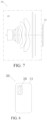
- an embodiment of the present application further provides a camera module 20.
- the camera module 20 includes a photosensitive chip 21 and the optical system 10 of any one of the above embodiments.
- a photosensitive surface of the photosensitive chip 21 is located on the imaging surface of the optical system 10.
- the light of an object that passes through the lens and is incident on the photosensitive surface can be converted into an electrical signal of an image.
- the photosensitive chip can be a CMOS sensor (Complementary Metal Oxide Semiconductor) or a CCD sensor (Charge Coupled Device).
- the camera module 20 can be an imaging module integrated into an electronic device 30 or an independent lens.
- an embodiment of the present application further provides the electronic device 30.
- the electronic device 30 includes a housing 31 and the lens module 20 of the above embodiment.
- the lens module 20 is disposed in the housing 31.
- the electronic device 30 may be, but is not limited to, an automobile, a monitor, a smart phone, a computer, a smart watch, or the like.
Landscapes
- Physics & Mathematics (AREA)
- General Physics & Mathematics (AREA)
- Optics & Photonics (AREA)
- Lenses (AREA)
Applications Claiming Priority (1)
| Application Number | Priority Date | Filing Date | Title |
|---|---|---|---|
| CN202311211261.3A CN117215039A (zh) | 2023-09-19 | 2023-09-19 | 光学系统、摄像模组和电子设备 |
Publications (2)
| Publication Number | Publication Date |
|---|---|
| EP4459352A2 true EP4459352A2 (de) | 2024-11-06 |
| EP4459352A3 EP4459352A3 (de) | 2025-03-19 |
Family
ID=89038573
Family Applications (1)
| Application Number | Title | Priority Date | Filing Date |
|---|---|---|---|
| EP24201333.2A Pending EP4459352A3 (de) | 2023-09-19 | 2024-09-19 | Optisches system, kameramodul und elektronische vorrichtung |
Country Status (3)
| Country | Link |
|---|---|
| US (1) | US20250093623A1 (de) |
| EP (1) | EP4459352A3 (de) |
| CN (1) | CN117215039A (de) |
Families Citing this family (2)
| Publication number | Priority date | Publication date | Assignee | Title |
|---|---|---|---|---|
| CN117806007A (zh) * | 2023-12-28 | 2024-04-02 | 江西欧菲光学有限公司 | 光学镜头、摄像模组及电子设备 |
| CN119828315B (zh) * | 2025-03-19 | 2025-07-08 | 江西欧菲光学有限公司 | 光学系统、摄像模组和电子设备 |
Family Cites Families (1)
| Publication number | Priority date | Publication date | Assignee | Title |
|---|---|---|---|---|
| CN113391430B (zh) * | 2021-05-26 | 2024-01-09 | 江西欧菲光学有限公司 | 光学系统、镜头模组和电子设备 |
-
2023
- 2023-09-19 CN CN202311211261.3A patent/CN117215039A/zh active Pending
-
2024
- 2024-09-19 EP EP24201333.2A patent/EP4459352A3/de active Pending
- 2024-09-19 US US18/889,595 patent/US20250093623A1/en active Pending
Also Published As
| Publication number | Publication date |
|---|---|
| EP4459352A3 (de) | 2025-03-19 |
| US20250093623A1 (en) | 2025-03-20 |
| CN117215039A (zh) | 2023-12-12 |
Similar Documents
| Publication | Publication Date | Title |
|---|---|---|
| US11630283B2 (en) | Optical imaging lens | |
| EP3896510A1 (de) | Optisches system, bildaufnahmevorrichtung und elektronische vorrichtung | |
| EP4459352A2 (de) | Optisches system, kameramodul und elektronische vorrichtung | |
| CN111443461A (zh) | 光学系统、镜头模组和电子设备 | |
| US7072123B2 (en) | Imaging lens including three lens components | |
| CN112327458B (zh) | 光学系统、摄像模组及电子设备 | |
| CN111239988B (zh) | 光学系统、镜头模组和电子设备 | |
| CN110426829A (zh) | 摄像用光学镜头组、取像装置及电子装置 | |
| US12105263B2 (en) | Optical system, lens module, and electronic device | |
| US12003836B2 (en) | Optical system, lens module, and electronic device | |
| CN112130286B (zh) | 光学成像镜头 | |
| CN114114636B (zh) | 光学镜片组 | |
| EP4528349A1 (de) | Optisches system, linsenmodul und elektronische vorrichtung | |
| CN111965789A (zh) | 光学镜头、摄像装置及终端 | |
| CN111239971A (zh) | 光学系统、摄像模组及电子装置 | |
| CN212111955U (zh) | 光学系统、镜头模组和电子设备 | |
| WO2021196030A1 (zh) | 光学系统、镜头模组和电子设备 | |
| EP4633178A1 (de) | Kameramodul und elektronische vorrichtung | |
| CN111142240B (zh) | 光学系统、镜头模组和电子设备 | |
| EP4443211A2 (de) | Optisches system, linsenmodul, und elektronisches gerät | |
| CN213122416U (zh) | 光学系统、镜头模组和电子设备 | |
| CN213149353U (zh) | 光学系统、镜头模组和电子设备 | |
| CN113009676A (zh) | 光学系统、摄像模组及电子设备 | |
| CN219978613U (zh) | 光学系统、摄像模组和电子设备 | |
| EP3933475A1 (de) | Optisches system, linsenmodul und elektronische vorrichtung |
Legal Events
| Date | Code | Title | Description |
|---|---|---|---|
| PUAI | Public reference made under article 153(3) epc to a published international application that has entered the european phase |
Free format text: ORIGINAL CODE: 0009012 |
|
| STAA | Information on the status of an ep patent application or granted ep patent |
Free format text: STATUS: THE APPLICATION HAS BEEN PUBLISHED |
|
| AK | Designated contracting states |
Kind code of ref document: A2 Designated state(s): AL AT BE BG CH CY CZ DE DK EE ES FI FR GB GR HR HU IE IS IT LI LT LU LV MC ME MK MT NL NO PL PT RO RS SE SI SK SM TR |
|
| PUAL | Search report despatched |
Free format text: ORIGINAL CODE: 0009013 |
|
| AK | Designated contracting states |
Kind code of ref document: A3 Designated state(s): AL AT BE BG CH CY CZ DE DK EE ES FI FR GB GR HR HU IE IS IT LI LT LU LV MC ME MK MT NL NO PL PT RO RS SE SI SK SM TR |
|
| RIC1 | Information provided on ipc code assigned before grant |
Ipc: G02B 13/00 20060101ALI20250210BHEP Ipc: G02B 9/62 20060101AFI20250210BHEP |
|
| STAA | Information on the status of an ep patent application or granted ep patent |
Free format text: STATUS: REQUEST FOR EXAMINATION WAS MADE |
|
| 17P | Request for examination filed |
Effective date: 20250908 |
|
| RAP3 | Party data changed (applicant data changed or rights of an application transferred) |
Owner name: JIANGXI OFILM OPTICAL CO., LTD. |