EP4459346A2 - Faseroptisches kabel mit metallpanzerung - Google Patents
Faseroptisches kabel mit metallpanzerung Download PDFInfo
- Publication number
- EP4459346A2 EP4459346A2 EP24174070.3A EP24174070A EP4459346A2 EP 4459346 A2 EP4459346 A2 EP 4459346A2 EP 24174070 A EP24174070 A EP 24174070A EP 4459346 A2 EP4459346 A2 EP 4459346A2
- Authority
- EP
- European Patent Office
- Prior art keywords
- optical fiber
- fiber cable
- layer
- overlap region
- optical fibers
- Prior art date
- Legal status (The legal status is an assumption and is not a legal conclusion. Google has not performed a legal analysis and makes no representation as to the accuracy of the status listed.)
- Pending
Links
Images

Classifications
-
- G—PHYSICS
- G02—OPTICS
- G02B—OPTICAL ELEMENTS, SYSTEMS OR APPARATUS
- G02B6/00—Light guides; Structural details of arrangements comprising light guides and other optical elements, e.g. couplings
- G02B6/44—Mechanical structures for providing tensile strength and external protection for fibres, e.g. optical transmission cables
- G02B6/4401—Optical cables
- G02B6/4429—Means specially adapted for strengthening or protecting the cables
- G02B6/443—Protective covering
-
- G—PHYSICS
- G02—OPTICS
- G02B—OPTICAL ELEMENTS, SYSTEMS OR APPARATUS
- G02B6/00—Light guides; Structural details of arrangements comprising light guides and other optical elements, e.g. couplings
- G02B6/44—Mechanical structures for providing tensile strength and external protection for fibres, e.g. optical transmission cables
- G02B6/4401—Optical cables
- G02B6/4429—Means specially adapted for strengthening or protecting the cables
- G02B6/443—Protective covering
- G02B6/4431—Protective covering with provision in the protective covering, e.g. weak line, for gaining access to one or more fibres, e.g. for branching or tapping
-
- G—PHYSICS
- G02—OPTICS
- G02B—OPTICAL ELEMENTS, SYSTEMS OR APPARATUS
- G02B6/00—Light guides; Structural details of arrangements comprising light guides and other optical elements, e.g. couplings
- G02B6/44—Mechanical structures for providing tensile strength and external protection for fibres, e.g. optical transmission cables
- G02B6/4401—Optical cables
- G02B6/4429—Means specially adapted for strengthening or protecting the cables
- G02B6/443—Protective covering
- G02B6/4432—Protective covering with fibre reinforcements
-
- G—PHYSICS
- G02—OPTICS
- G02B—OPTICAL ELEMENTS, SYSTEMS OR APPARATUS
- G02B6/00—Light guides; Structural details of arrangements comprising light guides and other optical elements, e.g. couplings
- G02B6/44—Mechanical structures for providing tensile strength and external protection for fibres, e.g. optical transmission cables
- G02B6/4401—Optical cables
- G02B6/4429—Means specially adapted for strengthening or protecting the cables
- G02B6/44384—Means specially adapted for strengthening or protecting the cables the means comprising water blocking or hydrophobic materials
-
- G—PHYSICS
- G02—OPTICS
- G02B—OPTICAL ELEMENTS, SYSTEMS OR APPARATUS
- G02B6/00—Light guides; Structural details of arrangements comprising light guides and other optical elements, e.g. couplings
- G02B6/44—Mechanical structures for providing tensile strength and external protection for fibres, e.g. optical transmission cables
- G02B6/4479—Manufacturing methods of optical cables
- G02B6/4486—Protective covering
- G02B6/4488—Protective covering using metallic tubes
Definitions
- Embodiments of the present disclosure relate to the field of telecommunication fiber, and more particularly, relates to an optical fiber cable with metal armoring that can be beneficial to reprocessing again of cost.
- This application claims the benefit of Indian Application No. "202311032006” titled “OPTICAL FIBER CABLE WITH METAL ARMORING” filed by the applicant on May 23, 2024 , which is incorporated herein by reference in its entirety.
- Optical fibers are widely used to transmit information or data in the form of light from one place to another.
- the optical fibers are disposed within the optical fiber cable.
- Fiber optic cables include one or more optical fibers or other optical waveguides that conduct optical signals, for example carrying voice, data, video, or other information.
- optical fibers are placed in a tubular assembly.
- a tube may be disposed inside an outer jacket or may form the outer jacket. In either case, the tube typically provides at least some level of protection for the fibers contained therein.
- Optical fibers are ordinarily susceptible to damage from water and physical stress. Without an adequate barrier, moisture may migrate into a fiber optic cable and weaken or destroy the cable's optical fibers. Without sufficient physical protection, stress or shock associated with handling the fiber optic cable may transfer to the optical fibers, causing breakage or stress-induced signal attenuation.
- Another conventional technology for protecting optical fibers entails placing a water absorbent chemical, such as water-swellable material, within the cable.
- the chemical absorbs water that may inadvertently enter the cable, and swells to prevent the water from traveling down long lengths of cable and degrading the delicate optical fibers.
- particles of the water absorbent chemical are mixed with the gel discussed above, and the mixture is inserted into the cable. This approach typically suffers from the same drawbacks as using a pure form of a gel; gels and related materials are messy and difficult to process.
- a water-swellable chemical is applied to the surface of a tape or a yarn that is inserted in the cable lengthwise. If water enters the cable, the water-swellable chemical interacts with the water and swells to impede and stop water flow lengthwise along the cable.
- a water blocking tape gets a reverse fold during manufacturing and optical fibers come out of it. If armour tape is right above, the bunches of optical fibers can trap in between two ends of armour tape and can lead to damage in optical fibers.
- US6256438B1 discloses fibers enclosed by a metal armour having a water swellable coating on its inner surface. The reference also discloses about use of a separate water swellable layer.
- US7590322B2 discloses about a water blocking tape over the ribbon stack and an overlapping position.
- the reference further discloses about a metal armour layer that is positioned above a central tube.
- EP1170614A1 discloses an electro chrome coated steel (ECCS) tape with an overlap portion of at least 2mm.
- the ECCS is made up of a water blocking material that is applied over its inner surface.
- the optical fiber cables of the prior art references remain weaker and thereby the optical fibers are prone to damage.
- optical communication industry requires a solution that ensures no damage to optical fibers due to minor fluctuations in manufacturing process while overcoming the drawbacks of existing designs.
- the invention addresses challenges in metal armoured optical fiber cables where a water-blocking tape may reverse fold, causing optical fibers to protrude. This situation leads to potential damage, as optical fibers can get trapped between overlapping armour tape ends.
- the present disclosure proposes an optical fiber cable with metal armoring that provides enhanced protection providing a versatile and comprehensive solution to address the challenges in the optical communication industry.
- Embodiments of the present disclosure relates to optical fiber cable characterized in that a plurality of optical fibers, a first layer wrapped around the plurality of optical fibers , a second layer that is wrapped around the first layer.
- the first layer comprises first and second end portions such that the first end portion overlaps the second end portion to define a first overlap region.
- the first overlap region has a first predefined width (W1) along an axial length of the optical fiber cable.
- the second layer comprises third and fourth end portions such that the third end portion overlaps the fourth end portion to define a second overlap region.
- the second overlap region has a second predefined width (W2) along the axial length of the optical fiber cable.
- the first overlap region and the second overlap region are positioned differently at one or more cross-section along the axial length of the optical fiber cable.
- first layer is made of at least one of, a water blocking tape (WBT) and a mica tape.
- WBT water blocking tape
- the second layer is made of a metallic tape.
- the first and second overlap regions comprising first and second centres such that an angle between
- the first and second overlap regions comprises first and second center such that an angle between
- the first and second overlap regions comprises first and second centers such that an angle between
- the optical fiber cable further comprises one or more ripcords that are positioned between the first and second layers.
- one or more ripcords are positioned between the first overlap region and the second overlap region.
- the plurality of optical fibers is in the form of one of, bunches of ribbons and loose fibers.
- Each ribbon of the bunches of ribbons is an intermittently bonded ribbon (IBR).
- IBR intermittently bonded ribbon
- a set of optical fibers of the plurality of optical fibers are disposed parallel to each other such that the set of optical fibers of the plurality of optical fibers are intermittently bonded by a plurality of bonded portions separated by a plurality of unbonded portions.
- the first predefined width (W1) is in a range between 5 millimeters (mm) and 10 mm.
- the second predefined width (W2) is in a range between 2 millimeters (mm) and 6 mm.
- the first predefined width (W1) is in a range between 5 millimeters (mm) and 10 mm.
- the second predefined width (W2) is in a range between 2 millimeters (mm) and 6 mm.
- optical fiber cable is illustrated in the accompanying drawings, which like reference letters indicate corresponding parts in the various figures. It should be noted that the accompanying figure is intended to present illustrations of exemplary embodiments of the present disclosure. This figure is not intended to limit the scope of the present disclosure. It should also be noted that the accompanying figure is not necessarily drawn to scale.
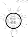
- Fig. 1 is a pictorial snapshot illustrating a cross-sectional view of an optical fiber cable in accordance with one embodiment of the present disclosure.
- the optical fiber cable 100 may be installed through various aerial overhead poles or laid inside various ducts that may be used in different applications.
- the optical fiber cable 100 may have a plurality of optical fibers 1 02a-102n (hereinafter collectively referred to and designated as "the optical fibers 102"), a first layer 104, a second layer 106, one or more ripcords 108a-108n (hereinafter collectively referred to and designated as "the ripcords 108"), and a sheath 110.
- the first layer 104 may have first and second end portions 112, 114 and the second layer 106 may have third and fourth end portions 116, 118.
- the optical fibers 102 may be disposed within the optical fiber cable 100. Particularly, the optical fibers 102 may extend up to a length of the optical fiber cable 100. Moreover, each optical fiber of the optical fibers 102 may be a cylindrical dielectric waveguide that may facilitate transmission of light along the length of the optical fiber cable 100. Further, each optical fiber of the optical fibers 102 may have a core (not shown) and a clad layer (not shown) such that the clad layer may surround the core. Specifically, the light may travel through the core of each optical fiber of the optical fibers 102 and the clad layer may be adapted to prevent leakage of the light out of each optical fiber of the optical fibers 102.
- the core and the clad layer may be made up of a dielectric material.
- each optical fiber of the optical fibers 102 may be, but not limited to, a single mode fiber, a multi-mode fiber, a single core fiber, and a multi-core fiber. Aspects of the present disclosure are intended to include and/or otherwise cover any type of the optical fiber of the optical fibers 102, without deviating from the scope of the present disclosure.
- the optical fibers 102 may be in the form of, but not limited to, bunches of ribbons 120a-120n (hereinafter collectively referred to and designated as "the ribbons 120") and loose fibers.
- Each ribbon of the bunches of ribbons 120 may be formed by grouping a set of optical fibers of the optical fibers 102.
- grouping the set of optical fibers of the optical fibers 102 may involve adjoining or binding the set of optical fibers of the optical fibers 102.
- the optical fibers 102 may be in form of, but not limited to, stacks of ribbons, bundles of ribbons, and intermittently bonded ribbon (IBR) bundles.
- IBR intermittently bonded ribbon
- each ribbon of the ribbons 120 may be an intermittently bonded ribbon (IBR).
- IBR of the IBRs may have a set of optical fibers of the optical fibers 102 such that the set of optical fibers are disposed parallel to each other.
- the set of optical fibers of the optical fibers 102 may be intermittently bonded by a plurality of bonded portions separated by a plurality of unbonded portions.
- each IBR of the IBRs may be placed without any binding element.
- each IBR of the IBRs may be placed with a binding element.
- each IBR of the IBRs may be bound by way of one or more binders to form bundles of IBRs.
- Aspects of the present disclosure are intended to include and/or otherwise cover any form of the optical fiber of the optical fibers 102, without deviating from the scope of the present disclosure.
- the first layer 104 may be wrapped around the optical fibers 102.
- the first end portion 112 may overlap with the second end portion 114 to define a first overlap region 122 while wrapping around the optical fibers 102.
- the first overlap region 122 may have a first predefined width (W1) along an axial length of the optical fiber cable 100.
- the first layer 104 may be, but not limited to, a water blocking tape (WBT) and a mica tape.
- WBT water blocking tape
- the first layer 104 may be a fire-retardant water blocking tape, a heat barrier tape, a polyester tape, and the like. Aspects of the present disclosure are intended to include and/or otherwise cover any type of the first layer 104, without deviating from the scope of the present disclosure.
- the second layer 106 may be wrapped around the first layer 104.
- the third end portion 116 may overlap with the fourth end portion 118 to define a second overlap region 124 while wrapping around the first layer 104.
- the second overlap region 124 may have a second predefined width (W2) along the axial length of the optical fiber cable 100.
- first overlap region 122 and the second overlap region 124 may be positioned differently at one or more cross-section along the axial length of the optical fiber cable 100.
- first overlap region 122 and the second overlap region 124 may not co-exist or overlap at any cross section along the axial length of the optical fiber cable 100.
- first overlap region 122 and the second overlap region 124 may be spaced apart within an angular range at one or more cross-section along the axial length of the optical fiber cable 100.
- the second layer 106 may be a metallic tape.
- the second layer 106 may be, but not limited to, a metal armor and an electrolytic chrome-coated steel (ECCS) tape.
- ECCS electrolytic chrome-coated steel
- the first and second overlap regions 122 and 124 have first and second centers 126 and 128 such that an angle between (i) a plane joining the first center 126 with a center 130 of the optical fiber cable 100 and (ii) a plane joining the second center 128 with the center 130 of the optical fiber cable 100 may be restricted by an angle of 180 Degrees (180°) with a tolerance value of 45 Degrees (45°).
- the angle between the first and second centers 126 and 128 may be restricted to 180 0 ⁇ 45° to prevent the optical fibers 102 to come out from the optical fiber cable 100. Further, during manufacturing or handling of the optical fibers 102, the optical fibers 102 may come out of the first layer 104, however, by virtue of the angle of 180 0 ⁇ 45° between the first and second centers 126 and 128, so that the optical fibers 102 may not get trapped inside the overlap region 124 of the second layer 106 and prevent physical damage of the optical fibers 102.
- the angle between the first and second centers 126 and 128 may be restricted to 90° ⁇ 45° to prevent the optical fibers 102 to come out from the optical fiber cable 100. Further, during manufacturing or handling of the optical fibers 102, the optical fibers 102 may come out of the first layer 104, however, by virtue of the angle of 90° ⁇ 45° between the first and second centers 126 and 128, the optical fibers 102 may not get trapped inside the overlap region 124 of the second layer 106 and to prevent physical damage of the optical fibers 102.
- the plane joining the first center 126 with the center 130 of the optical fiber cable 100 and (ii) the plane joining the second center 128 with the center 130 of the optical fiber cable 100 may be restricted by an angle of 270 Degrees (270°) with a tolerance value of 45 Degrees (45°).
- the angle between the first and second centers 126 and 128 may be restricted to 270° ⁇ 45° may prevent the optical fibers 102 from coming out from the optical fiber cable 100. Further, during manufacturing or handling of the optical fibers 102, the optical fibers 102 may come out of the first layer 104, however, by virtue of the angle of 270° ⁇ 45° between the first and second centers 126 and 128, the optical fibers 102 may not get trapped inside the overlap region 124 of the second layer 106 and to prevent physical damage of the optical fibers 102.
- the ripcords 108 may be positioned between the first and second layers 104 and 106.
- the ripcords 108 may be adapted to facilitate tearing of the sheath 110 and the second layer 106.
- the ripcords 108 may be adapted to facilitate tearing of the sheath 110 and the second layer 106 to access the optical fibers 102.
- the one or more ripcords 108a-108n may be positioned between the first overlap region 122 and the second overlap region 124 at any cross-section along the axial length of the optical fiber cable 100.
- the first predefined width (W1) may be in a range between 5 millimeters (mm) and 10 mm. Specifically, the first predefined width (W1) may be preferably kept in the range between 5 millimeters (mm) and 10 mm, as the first predefined width (W1) being lesser than 5 mm may produce the first overlap region 122 of a smaller width, which may cause the optical fibers 102 to come out from the first overlap region 122. Further, the first predefined width (W1) being greater than 10 mm, may require additional material to be placed in the optical fiber cable 100, to leave low space for the optical fibers 102.
- the second predefined width (W2) may be in a range between 2 mm and 6 mm.
- the second predefined width (W2) may be preferably kept in the range between 2 mm and 6 mm, as the second predefined width (W2) being lesser than 2 mm, may produce the second overlap region 124 of a smaller width, which may add difficulty in manufacturing the optical fiber cable 100.
- the second predefined width (W2) being greater than 6 mm, may require additional material to be placed in the optical fiber cable 100, which may leave low space for the optical fibers 102.
- material of the sheath 110 may be, but not limited to, polyethylene, low-smoke zero-halogen (LSZH), polyvinyl chloride (PVC), thermoplastic polyurethane (TPU), and the like.
- LZH low-smoke zero-halogen
- PVC polyvinyl chloride
- TPU thermoplastic polyurethane
- the first layer 104 and the second layer 106 are at least partially in contact with each other along the axial length of the optical fiber cable 100.
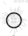
- Fig. 2 is a pictorial snapshot illustrating a cross-sectional view of another optical fiber cable in accordance with another embodiment of the present disclosure.
- the optical fiber cable 200 may be substantially similar to the optical fiber cable 100, in terms of structural and functional aspects and the like elements of the optical fiber cable 100.
- the optical fiber cable 200 is provided with a plurality of strength members 202a-202n (hereinafter collectively referred to and designated as "the strength members 202") embedded in the sheath 110.
- the strength members 202 may provide the required tensile strength and stiffness to the optical fiber cable 200.
- each strength member of the strength members 202 may be made up of, but not limited to, a reinforced aramid yarn, a reinforced glass yarn, and steel. Aspects of the present disclosure are intended to include and/or otherwise cover any type of material for each strength member of the strength members 202, without deviating from the scope of the present disclosure.
- the plane joining the first center 126 with the center 130 of the optical fiber cable 100 and (ii) the plane joining the second center 128 with the center 130 of the optical fiber cable 100 may be restricted by an angle of 90 Degrees (90°) with a tolerance value of 45 Degrees (45°).
- the angle between the first and second centers 126 and 128 may be restricted to 90 0 ⁇ 45° prevent the optical fibers 102 to come out from the optical fiber cable 100.
- the optical fibers 102 may come out of the first layer 104, however, by virtue of the angle of 90 0 ⁇ 45° between the first and second centers 126 and 128, the optical fibers 102 may not get trapped inside the second overlap region 124 of the second layer 106. This may prevent physical damage of the optical fibers 102.
- the first predefined width (W1) may be in a range between 5 millimeters (mm) and 10 mm.
- the first predefined width (W1) may be preferably kept in the range between 5 mm and 10 mm, as the first predefined width (W1) being lesser than 5 mm, may produce the first overlap region 122 of smaller width causing the optical fibers 102 to come out from the first overlap region 122.
- the first predefined width (W1) being greater than 10 mm may require additional material to be placed in the optical fiber cable 100 to leave low space for the optical fibers 102.
- the second predefined width (W2) may be in a range between 2 mm and 6 mm.
- the second predefined width (W2) may be preferably kept in the range between 2 mm and 6 mm, as the second predefined width (W2) being lesser than 2 mm, produces the second overlap region 124 of a smaller width, which may add difficulty in manufacturing the optical fiber cable 100.
- the second predefined width (W2) being greater than 6 mm requires additional material to be placed in the optical fiber cable 100 that leaves low space for the optical fibers 102.
- Fig. 3 is a pictorial snapshot illustrating perspective view of the optical fiber cable in accordance with an embodiment of the present disclosure.
- the first overlap region 122 of the first layer 104 and the second overlap region 124 of the second layer 106 are shown.
- the first overlap region 122 is disposed diametrically opposite to the second overlap region 124.
- the angle between (i) the plane joining the first center 126 with the center 130 of the optical fiber cable 100 and (ii) the plane joining the second center 128 with the center 130 of the optical fiber cable 100 may be restricted to 180 0 ⁇ 45° that may prevent the optical fibers 102 to come out from the optical fiber cable 100.
- the optical fibers 102 may come out of the first layer 104, however, by virtue of the angle of 180 0 ⁇ 45° between the first and second centers 126 and 128, the optical fibers 102 may not get trapped inside the overlap region 124 of the second layer 106 and this prevents physical damage of the optical fibers 102.
- the optical fiber cable (100) comprises a plurality of optical fibers (102a-102n), a first layer (104), a second layer (106
- the first layer (104) is wrapped around the plurality of optical fibers (102a-102n), where the first layer (104) includes first and second end portions (112, 114) such that the first end portion (112) overlaps the second end portion (114) to define a first overlap region (122), where the first overlap region (122) has a first predefined width (W1) along an axial length of the optical fiber cable (100).
- the second layer (106) is wrapped around the first layer (104), and comprises third and fourth end portions (116, 118) such that the third end portion (116) overlaps the fourth end portion (118) to define a second overlap region (124), where the second overlap region (124) has a second predefined width (W2) along the axial length of the optical fiber cable (100).
- first overlap region (122) and the second overlap region (124) are positioned at an angle greater than zero degree with respect to the center of the optical fiber cable (100) when viewed in one or more cross-section the optical fiber cable (100).
- the first layer (104) is made of at least one of, a water blocking tape (WBT) and a mica tape.
- the second layer (106) is made up of a metallic tape.
- the disclosed optical fiber cable introduces a layer configuration, with a first layer comprising a water-blocking tape or mica tape, and a second layer comprising a metallic tape.
- first and second overlap regions are strategically positioned differently along the axial length, overcoming weaknesses seen in conventional cables.
- the optical fiber cable design with the layer placement offers advantages such as reduced cable diameter, reduced scrap, enhanced tolerance to manufacturing process. This configuration ensures optimal performance and reliability.
- first and second layers comprising water-blocking or mica tape and metallic tape, respectively.
- the distinct positioning of overlap regions along the axial length ensures that potential weaknesses are minimized, preventing optical fiber damage.
- the synergistic effect results from the combination of water-blocking or mica tape in the first layer and metallic tape in the second layer, strategically placed to avoid weaknesses.
- the distinct positioning of overlap regions ensures that potential damage points are minimized, enhancing the overall robustness and reliability of the optical fiber cable.
- the optical fiber cable with the metal armor layer configuration demonstrates improved prevention of optical fiber damage in armoured cables. This makes the cable suitable for faster manufacturing while ensuring reliable communication in critical environments.
- the optical fiber cables 100 and 200 have a reduced diameter.
- the optical fibers 102 are protected from any kind of physical damage. Further, by virtue of relative positioning of the first overlap region 122 with respect to the second overlap region 124, the optical fibers 102 may not get trapped in the second layer 106, if by any chance the optical fibers 102 comes out from the first layer 104.
Landscapes
- Physics & Mathematics (AREA)
- General Physics & Mathematics (AREA)
- Optics & Photonics (AREA)
- Light Guides In General And Applications Therefor (AREA)
Applications Claiming Priority (1)
| Application Number | Priority Date | Filing Date | Title |
|---|---|---|---|
| IN202311032006 | 2023-05-05 |
Publications (2)
| Publication Number | Publication Date |
|---|---|
| EP4459346A2 true EP4459346A2 (de) | 2024-11-06 |
| EP4459346A3 EP4459346A3 (de) | 2025-02-26 |
Family
ID=91022768
Family Applications (1)
| Application Number | Title | Priority Date | Filing Date |
|---|---|---|---|
| EP24174070.3A Pending EP4459346A3 (de) | 2023-05-05 | 2024-05-03 | Faseroptisches kabel mit metallpanzerung |
Country Status (1)
| Country | Link |
|---|---|
| EP (1) | EP4459346A3 (de) |
Citations (3)
| Publication number | Priority date | Publication date | Assignee | Title |
|---|---|---|---|---|
| US6256438B1 (en) | 1999-10-29 | 2001-07-03 | Siecor Operations, Llc | Fiber optic drop cable |
| EP1170614A1 (de) | 2000-06-07 | 2002-01-09 | Lucent Technologies Inc. | Trocken abgeblocktes und verstärktes Kabel mit reduziertem Wassereindringvermögen |
| US7590322B2 (en) | 2007-03-09 | 2009-09-15 | Superior Essex Communications Lp | Fiber optic cable with enhanced saltwater performance |
Family Cites Families (3)
| Publication number | Priority date | Publication date | Assignee | Title |
|---|---|---|---|---|
| US4844575A (en) * | 1987-04-10 | 1989-07-04 | American Telephone And Telegraph Company, At&T Bell Laboratories | Optical fiber cable |
| US9482835B2 (en) * | 2014-06-27 | 2016-11-01 | Corning Optical Communications LLC | Extreme environment optical fiber cable with crack-resistant layer |
| CA3245683A1 (en) * | 2022-03-14 | 2025-06-13 | Fujikura Ltd. | FIBER OPTIC CABLE AND FIBER OPTIC CABLE PRODUCTION METHOD |
-
2024
- 2024-05-03 EP EP24174070.3A patent/EP4459346A3/de active Pending
Patent Citations (3)
| Publication number | Priority date | Publication date | Assignee | Title |
|---|---|---|---|---|
| US6256438B1 (en) | 1999-10-29 | 2001-07-03 | Siecor Operations, Llc | Fiber optic drop cable |
| EP1170614A1 (de) | 2000-06-07 | 2002-01-09 | Lucent Technologies Inc. | Trocken abgeblocktes und verstärktes Kabel mit reduziertem Wassereindringvermögen |
| US7590322B2 (en) | 2007-03-09 | 2009-09-15 | Superior Essex Communications Lp | Fiber optic cable with enhanced saltwater performance |
Also Published As
| Publication number | Publication date |
|---|---|
| EP4459346A3 (de) | 2025-02-26 |
Similar Documents
| Publication | Publication Date | Title |
|---|---|---|
| EP1910879B1 (de) | Glasfaserkabel und anordnungen für faser zu teilnehmeranwendungen | |
| AU2007101252B4 (en) | Dry fiber optic cables and assemblies | |
| EP2725399B1 (de) | Glasfaserkabel | |
| KR102469509B1 (ko) | 외장형 가요성 광섬유 조립체 | |
| WO2003016974A1 (en) | Fiber optic cable with profiled group of optical fibers | |
| US6922511B2 (en) | Fiber optic assemblies and cables having subunits with a security feature | |
| US20240103240A1 (en) | Thin film bundled cable | |
| EP4459346A2 (de) | Faseroptisches kabel mit metallpanzerung | |
| WO2015195095A1 (en) | Central-tube optical-fiber cable | |
| US20250341693A1 (en) | Optical fiber cable with metal armoring | |
| EP4194915A1 (de) | Ungebondetes bewehrtes glasfaserkabel | |
| US20240053561A1 (en) | Micro sheath buffer tube with rollable ribbons | |
| EP4650844A1 (de) | Bewehrtes glasfaserkabel mit einfachem zugang | |
| EP4579304A1 (de) | Faseroptisches kabel mit einer fest gepufferten multifasereinheit | |
| EP4485031A1 (de) | Faseroptisches kabel mit einem oder mehreren schrumpfschutzelementen | |
| US20250355206A1 (en) | Armored Optical Fiber Cable | |
| EP4465103A1 (de) | Faseroptisches kabel mit metallpanzerung | |
| EP4726446A1 (de) | Gehärteter verbinder zum verbinden mindestens einer optischen faser mit einem optischen faseranschluss | |
| US20260104556A1 (en) | Hardened connector having locking feature for engaging with an optical fiber terminal | |
| US20230221514A1 (en) | Optical fiber cable with different binder pitch | |
| EP4421549A2 (de) | Faseroptisches freileitungskabel | |
| EP4468049A1 (de) | Faseroptisches kabel mit mehreren schlitzen | |
| SATO et al. | Design of Ultra-High-Density Optical Fiber Cable With Rollable 4-Fiber Ribbons |
Legal Events
| Date | Code | Title | Description |
|---|---|---|---|
| PUAI | Public reference made under article 153(3) epc to a published international application that has entered the european phase |
Free format text: ORIGINAL CODE: 0009012 |
|
| STAA | Information on the status of an ep patent application or granted ep patent |
Free format text: STATUS: THE APPLICATION HAS BEEN PUBLISHED |
|
| AK | Designated contracting states |
Kind code of ref document: A2 Designated state(s): AL AT BE BG CH CY CZ DE DK EE ES FI FR GB GR HR HU IE IS IT LI LT LU LV MC ME MK MT NL NO PL PT RO RS SE SI SK SM TR |
|
| PUAL | Search report despatched |
Free format text: ORIGINAL CODE: 0009013 |
|
| AK | Designated contracting states |
Kind code of ref document: A3 Designated state(s): AL AT BE BG CH CY CZ DE DK EE ES FI FR GB GR HR HU IE IS IT LI LT LU LV MC ME MK MT NL NO PL PT RO RS SE SI SK SM TR |
|
| RIC1 | Information provided on ipc code assigned before grant |
Ipc: G02B 6/44 20060101AFI20250121BHEP |
|
| STAA | Information on the status of an ep patent application or granted ep patent |
Free format text: STATUS: REQUEST FOR EXAMINATION WAS MADE |
|
| 17P | Request for examination filed |
Effective date: 20250826 |