EP4459270A1 - Radiation inspection system - Google Patents
Radiation inspection system Download PDFInfo
- Publication number
- EP4459270A1 EP4459270A1 EP22914864.8A EP22914864A EP4459270A1 EP 4459270 A1 EP4459270 A1 EP 4459270A1 EP 22914864 A EP22914864 A EP 22914864A EP 4459270 A1 EP4459270 A1 EP 4459270A1
- Authority
- EP
- European Patent Office
- Prior art keywords
- motor
- radiation
- conveying device
- inspection
- main body
- Prior art date
- Legal status (The legal status is an assumption and is not a legal conclusion. Google has not performed a legal analysis and makes no representation as to the accuracy of the status listed.)
- Pending
Links
Images

Classifications
-
- G—PHYSICS
- G01—MEASURING; TESTING
- G01N—INVESTIGATING OR ANALYSING MATERIALS BY DETERMINING THEIR CHEMICAL OR PHYSICAL PROPERTIES
- G01N23/00—Investigating or analysing materials by the use of wave or particle radiation, e.g. X-rays or neutrons, not covered by groups G01N3/00 – G01N17/00, G01N21/00 or G01N22/00
- G01N23/02—Investigating or analysing materials by the use of wave or particle radiation, e.g. X-rays or neutrons, not covered by groups G01N3/00 – G01N17/00, G01N21/00 or G01N22/00 by transmitting the radiation through the material
- G01N23/04—Investigating or analysing materials by the use of wave or particle radiation, e.g. X-rays or neutrons, not covered by groups G01N3/00 – G01N17/00, G01N21/00 or G01N22/00 by transmitting the radiation through the material and forming images of the material
- G01N23/046—Investigating or analysing materials by the use of wave or particle radiation, e.g. X-rays or neutrons, not covered by groups G01N3/00 – G01N17/00, G01N21/00 or G01N22/00 by transmitting the radiation through the material and forming images of the material using tomography, e.g. computed tomography [CT]
-
- G—PHYSICS
- G01—MEASURING; TESTING
- G01N—INVESTIGATING OR ANALYSING MATERIALS BY DETERMINING THEIR CHEMICAL OR PHYSICAL PROPERTIES
- G01N23/00—Investigating or analysing materials by the use of wave or particle radiation, e.g. X-rays or neutrons, not covered by groups G01N3/00 – G01N17/00, G01N21/00 or G01N22/00
- G01N23/02—Investigating or analysing materials by the use of wave or particle radiation, e.g. X-rays or neutrons, not covered by groups G01N3/00 – G01N17/00, G01N21/00 or G01N22/00 by transmitting the radiation through the material
- G01N23/04—Investigating or analysing materials by the use of wave or particle radiation, e.g. X-rays or neutrons, not covered by groups G01N3/00 – G01N17/00, G01N21/00 or G01N22/00 by transmitting the radiation through the material and forming images of the material
-
- G—PHYSICS
- G01—MEASURING; TESTING
- G01N—INVESTIGATING OR ANALYSING MATERIALS BY DETERMINING THEIR CHEMICAL OR PHYSICAL PROPERTIES
- G01N23/00—Investigating or analysing materials by the use of wave or particle radiation, e.g. X-rays or neutrons, not covered by groups G01N3/00 – G01N17/00, G01N21/00 or G01N22/00
- G01N23/02—Investigating or analysing materials by the use of wave or particle radiation, e.g. X-rays or neutrons, not covered by groups G01N3/00 – G01N17/00, G01N21/00 or G01N22/00 by transmitting the radiation through the material
- G01N23/06—Investigating or analysing materials by the use of wave or particle radiation, e.g. X-rays or neutrons, not covered by groups G01N3/00 – G01N17/00, G01N21/00 or G01N22/00 by transmitting the radiation through the material and measuring the absorption
-
- G—PHYSICS
- G01—MEASURING; TESTING
- G01V—GEOPHYSICS; GRAVITATIONAL MEASUREMENTS; DETECTING MASSES OR OBJECTS; TAGS
- G01V5/00—Prospecting or detecting by the use of ionising radiation, e.g. of natural or induced radioactivity
- G01V5/20—Detecting prohibited goods, e.g. weapons, explosives, hazardous substances, contraband or smuggled objects
- G01V5/22—Active interrogation, i.e. by irradiating objects or goods using external radiation sources, e.g. using gamma rays or cosmic rays
- G01V5/226—Active interrogation, i.e. by irradiating objects or goods using external radiation sources, e.g. using gamma rays or cosmic rays using tomography
-
- G—PHYSICS
- G01—MEASURING; TESTING
- G01N—INVESTIGATING OR ANALYSING MATERIALS BY DETERMINING THEIR CHEMICAL OR PHYSICAL PROPERTIES
- G01N2223/00—Investigating materials by wave or particle radiation
- G01N2223/40—Imaging
- G01N2223/419—Imaging computed tomograph
-
- G—PHYSICS
- G01—MEASURING; TESTING
- G01N—INVESTIGATING OR ANALYSING MATERIALS BY DETERMINING THEIR CHEMICAL OR PHYSICAL PROPERTIES
- G01N2223/00—Investigating materials by wave or particle radiation
- G01N2223/60—Specific applications or type of materials
- G01N2223/643—Specific applications or type of materials object on conveyor
-
- Y—GENERAL TAGGING OF NEW TECHNOLOGICAL DEVELOPMENTS; GENERAL TAGGING OF CROSS-SECTIONAL TECHNOLOGIES SPANNING OVER SEVERAL SECTIONS OF THE IPC; TECHNICAL SUBJECTS COVERED BY FORMER USPC CROSS-REFERENCE ART COLLECTIONS [XRACs] AND DIGESTS
- Y02—TECHNOLOGIES OR APPLICATIONS FOR MITIGATION OR ADAPTATION AGAINST CLIMATE CHANGE
- Y02E—REDUCTION OF GREENHOUSE GAS [GHG] EMISSIONS, RELATED TO ENERGY GENERATION, TRANSMISSION OR DISTRIBUTION
- Y02E30/00—Energy generation of nuclear origin
- Y02E30/30—Nuclear fission reactors
Definitions
- the present disclosure relates to the field of radiation inspection technology, in particular to a radiation inspection system.
- Imaging technologies for radiation inspection systems for inspection of objects to be inspected include DR (Digital Radiography) inspection technology and CT (Computed Tomography) inspection technology.
- the objects to be inspected include, for example, vehicles, containers, luggage, etc.
- the DR inspection technology uses two-dimensional digital imaging technology in which a radiation source and a detector module are fixed. It has the advantages that the inspection speed is fast, the pass rate of objects to be inspected is high, and metal and other dangerous goods are easy to determine; and it has the disadvantages that the amount of information on an object to be inspected obtained by the detector module is small, and explosives are difficult to determine accurately, and it is more suitable for forming planar images.
- the CT inspection technology mainly utilizes a CT reconstruction algorithm to reconstruct a tomographic image of an object to be inspected. It has the advantages that the amount of tomographic data information is large, and explosives can be determined accurately by reconstruction of tomographic images; and it has the disadvantages that the inspection speed is slow, and the pass rate of objects to be inspected is low.
- a scanning speed when an object to be inspected is inspected by using the DR inspection technology is higher than a scanning speed when the object to be inspected is inspected by using the CT inspection technology.
- a conveying device that conveys the object to be inspected needs to have the ability to convey the object to be inspected smoothly in a wide range of speeds.
- a self-travelling conveying device is often used to tow a vehicle to be inspected, and the conveying device needs to have the ability to tow the vehicle to be inspected smoothly in a wide range of speeds.
- scanning inspection of the vehicle to be inspected the vehicle to be inspected passes through a scanning area of an inspection channel under the traction of the conveying device, thereby scanning and imaging goods, such as containers, on the vehicle to be inspected so as to perform radiation inspection on the goods on the vehicle to be inspected.
- a conveying device of a radiation inspection system using the DR inspection technology is generally driven by a variable frequency motor.
- the variable frequency motor needs to work at a very low frequency, such as working at a frequency lower than 8Hz, and in this case, the variable frequency motor produces waveform distortion, and the motor generates heat, resulting in softened mechanical characteristics and a reduced torque, and it is difficult to meet the requirement of low-speed heavy-load smooth operation.
- each servo motor drives different driving wheels to implement adjustment of a conveying speed of a conveying device in such a manner that different servo motors are used to drive different driving wheels during inspection by the DR inspection technology and during inspection by the CT inspection technology.
- a servo driver performs automatic identification of servo motor parameters.
- the servo driver If the same servo driver drives two servo motors, the servo driver will identify incorrect servo motor parameters, and the servo motor cannot be well controlled, and alarming even occurs in the process of operation. Therefore, generally it needs to configure one servo motor correspondingly for one servo driver, leading to a high cost and great difficulty of control.
- An object of the present disclosure is to provide a radiation inspection system intended to simplify the control of its conveying device and save costs.
- the present disclosure provides a radiation inspection system, including:
- the radiation inspection system further includes a mode detecting device, wherein the mode detecting device is in signal connection with the radiation imaging device and the controller, and the mode detecting device is configured to monitor working parameters of the radiation imaging device and transmit the working parameters as a working mode signal to the controller.
- the radiation imaging device includes:
- the radiation imaging device includes one radiation source and one detector module corresponding to the radiation source, and the radiation source and the detector module switch between the DR inspection mode and the CT inspection mode.
- the conveying device includes a self-travelling conveying device, wherein the self-travelling conveying device includes a driving wheel connected to the conveying device main body, and the primary-secondary motor is in drive connection with the driving wheel.
- the radiation inspection system further includes a track, and the driving wheel is located on the track; and the conveying device further includes a limiting wheel, which cooperates with a lateral side of the track.
- the primary-secondary motor further includes a first connecting part and a second connecting part, wherein the first connecting part and the second connecting part each include two transmission parts having an axially connected state and an axially separated state, respectively;
- the speed reducer has an input shaft and an output shaft;
- the main motor is connected to the output shaft via the first connecting part;
- the sub-motor is connected to the input shaft via the second connecting part; and
- the primary-secondary motor is in drive connection with the conveying device main body by means of the main motor.
- the DR inspection technology and the CT inspection technology are used in combination, and the primary-secondary motor is in drive connection with the conveying device main body, and the primary-secondary motor combines the main motor and the sub-motor into a whole through the speed reducer, so that the primary-secondary motor has a large speed difference between a speed when the main motor is used for driving and a speed when the sub-motor is used for driving in the process of conveyance and positioning of the conveying device.
- the main motor and the sub-motor of the primary-secondary motor can be respectively matched with the DR inspection mode and the CT inspection mode of the radiation inspection system, and good matching between a scanning speed and a conveying speed can be achieved directly by a matching relationship between the main motor and the sub-motor of the primary-secondary motor and the DR inspection mode and the CT inspection mode, so the control of the conveying device can be simplified and the cost can be saved.
- orientation or position relations denoted by terms such as “front”, “rear”, “upper”, “lower”, “left”, “right”, “transverse”, “longitudinal”, “vertical”, “horizontal”, “top” and “bottom” are generally orientation or position relations illustrated based on the drawings, and are merely for the convenience of describing the present disclosure and simplifying description, and unless stated to the contrary, such terms do not indicate or imply the denoted devices or elements must have specific orientations or be constructed and operated in specific orientations, and thus cannot be construed as limiting the protection scope of the present disclosure; and orientation terms “inner” and “outer” refer to the inside and outside with respect to the contour of each component itself.
- the radiation inspection system mainly includes a radiation imaging device 1, a conveying device 2 and a controller 3.
- the radiation imaging device 1 includes at least one radiation source and at least one detector module, has a CT inspection mode and a DR inspection mode, and is configured to perform radiation inspection on an object to be inspected O passing through an inspection channel P.
- the conveying device 2 includes a conveying device main body 21, and a primary-secondary motor 22 in drive connection with the conveying device main body 21 to drive the conveying device main body 21 to move along the inspection channel P.
- the primary-secondary motor 22 includes a main motor 221, a sub-motor 223, and a speed reducer 225.
- the conveying device 2 may be, for example, a self-travelling conveying device, a plate chain conveying device, a belt conveying device, or the like.
- the controller 3 is in signal connection with the radiation imaging device 1 and the primary-secondary motor 22, and the controller 3 is configured such that when the radiation imaging device 1 is in the CT inspection mode, the conveying device main body 21 is in drive connection with the sub-motor 223 through the speed reducer 225 to convey the object to be inspected O under the drive of the sub-motor 223, and in the DR inspection mode, the conveying device main body 21 is in drive connection with the main motor 221 to convey the object to be inspected O under the drive of the main motor 221, wherein a conveying speed when the conveying device main body 21 is in drive connection with the main motor 221 is higher than a conveying speed when the conveying device main body is in drive connection with the sub-motor 223.
- the controller 3 may be embodied as a general-purpose processor, a programmable logic controller (PLC), a digital signal processor (DSP), an application specific integrated circuit (ASIC), a field-programmable gate array (FPGA) or other programmable logic device, a discrete gate or transistor logic device, a discrete hardware component, or any appropriate combination thereof, for performing functions described in the present disclosure.
- PLC programmable logic controller
- DSP digital signal processor
- ASIC application specific integrated circuit
- FPGA field-programmable gate array
- the DR inspection technology and the CT inspection technology are used in combination, and the primary-secondary motor 22 is in drive connection with the conveying device main body 21, and the primary-secondary motor 22 combines the main motor 221 and the sub-motor 223 into a whole through the speed reducer 225, so that the primary-secondary motor 22 has a large speed difference between a speed when the main motor 221 is used for driving and a speed when the sub-motor 223 is used for driving in the process of conveyance and positioning of the conveying device 2.
- the main motor 221 and the sub-motor 223 of the primary-secondary motor 22 can be respectively matched with the DR inspection mode and the CT inspection mode of the radiation inspection system, and good matching between a scanning speed and a conveying speed can be achieved directly by a matching relationship between the main motor 221 and the sub-motor 223 of the primary-secondary motor 22 and the DR inspection mode and the CT inspection mode, so the control of the conveying device can be simplified and the cost can be saved.
- an object to be inspected 0 is specifically a vehicle to be inspected.
- the radiation inspection system includes a radiation imaging device 1, a conveying device 2, a controller 3, a track 4, and a mode detecting device 5.
- the radiation imaging device 1 has the CT inspection mode and the DR inspection mode, and is configured to perform radiation inspection on an object to be inspected O passing through an inspection channel P.
- the vehicle to be inspected passes through a scanning area in the inspection channel P under the traction of the conveying device 2, thereby scanning and imaging goods, such as containers, on the vehicle to be inspected so as to perform radiation inspection on the goods on the vehicle to be inspected.
- a scanning speed when the radiation inspection system in the DR inspection mode as compared with the CT inspection mode is much higher than a scanning speed when the radiation inspection system is in the CT inspection mode.
- the conveying device 2 has an ability to tow the vehicle to be inspected smoothly in a wide range of speeds. In the present embodiments, the ratio of the highest conveying speed to the lowest conveying speed of the conveying device 2 is about 50.
- the radiation imaging device 1 includes a CT imaging part 11 and a DR imaging part 12.
- the CT imaging part 11 includes a first radiation source 111 and a first detector module 112 disposed corresponding to the first radiation source 111.
- the DR imaging part 12 includes a second radiation source 121 and a second detector module 122 disposed corresponding to the second radiation source 121. That is, at least one radiation source includes a first radiation source 111 and a second radiation source 121, and at least one detector module includes a first detector module 112 and a second detector module 122.
- the CT imaging part may, for example, be configured as a CT imaging part with a single energy output or multiple energy outputs.
- the radiation imaging device 1 may include one radiation source and one detector module corresponding to the radiation source.
- the radiation source and the detector module switch between the DR inspection mode and the CT inspection mode. That is, the radiation imaging device 1 only includes one imaging part, which can switch between the DR inspection mode and the CT inspection mode.
- the radiation imaging device 1 In the CT inspection mode, the radiation source and the detector module of the imaging part rotate, and the conveying device 2 conveys the object to be inspected O at a slow speed.
- the radiation source and the detector module of the imaging part are motionless, and the conveying device 2 conveys the object to be inspected O at a fast speed.
- the radiation imaging device 1 may also include three or more imaging parts.
- the CT imaging part and the DR imaging part are provided respectively, it is not excluded that two independent DR imaging parts may be provided to inspect the object to be inspected O from different view angles.
- the use of the DR inspection mode and the CT inspection mode may be switched according to radiation inspection needs. For example, for each vehicle to be inspected, scanning inspection can be first performed in the DR inspection mode to obtain a scanning image, then whether there is suspected prohibited goods is determined based on the scanning image, and if there is suspected prohibited goods, it also needs to determine the location of the suspected prohibited goods in the vehicle to be inspected. For a vehicle to be inspected that does not have suspected prohibited goods, it can be released directly after scanning inspection is completed. For a scanned vehicle with suspected prohibited goods, the location in the vehicle to be inspected where the suspected prohibited goods are located is subjected to scanning inspection in the CT inspection mode to make more accurate judgment. This is conducive to ensuring both inspection efficiency and accuracy degree for the DR inspection mode and the CT inspection mode.
- the conveying device 2 includes a conveying device main body 21, a primary-secondary motor 22, a driving wheel 23, a limiting wheel 24, a frequency converter 25, and a switching device 26.
- the primary-secondary motor 22 is in drive connection with the conveying device main body 21 to drive the conveying device main body 21 to move along the inspection channel P.
- the primary-secondary motor 22 includes a main motor 221, a first connecting part 222, a sub-motor 223, a second connecting part 224, and a speed reducer 225.
- the first connecting part 222 and the second connecting part 224 each include two transmission parts having an axially connected state and an axially separated state, respectively.
- the first connecting device 222 may, for example, be a clutch.
- the two transmission parts are two components of the clutch that clutch each other.
- the second connecting part 224 may, for example, be a coupling.
- the two transmission parts are two shaft connecting parts of the coupling.
- the speed reducer 225 has an input shaft 2251 and an output shaft 2252.
- the main motor 221 is connected to the output shaft 2252 via the first connecting part 222.
- the sub-motor 223 is connected to the input shaft 2251 via the second connecting part 224.
- the primary-secondary motor 22 is in drive connection with the conveying device main body 21 by means of the main motor 221.
- first connecting part 222 may be in a form other than a clutch, such as a coupling
- second connecting part 224 may be in a form other than a coupling, such as a clutch
- the primary-secondary motor 22 is a composite motor combining the higher-power main motor 221 with the lower-power sub-motor 223 by the speed reducer 225 to obtain an ultra-wide speed ratio.
- the sub-motor 223 is not power on and is in a braking state
- the two transmission parts of the first connecting part 222 are in the axially separated state
- the two transmission parts of the second connecting part 224 are also in the axially separated state
- the speed reducer 225 does not work, and at that time, a main shaft of the main motor 221 outputs a high speed.
- the primary-secondary motor in a working state shown in Fig. 2 corresponds to the DR scanning mode.
- the sub-motor 223 when the sub-motor 223 is powered on and works, the main motor 221 is not powered on, the two transmission parts of the first connecting part 222 are in the axially connected state, the two transmission parts of the second connecting part 224 are also in the axially connected state, the sub-motor 223 causes, through the speed reducer 225, the main motor 221 to rotate, the primary-secondary motor 22 relies on the sub-motor 223 for driving, and after the power of the sub-motor 223 is transmitted to a rotating shaft of the main motor 221 through the speed reducer 225, the rotating shaft of the main motor 221 outputs a low and smooth rotating speed.
- the primary-secondary motor in the working state shown in Fig. 3 corresponds to the CT scanning mode.
- the sub-motor 223 is in the braking state
- the main motor 221 is in the braking state
- the two transmission parts of the first connecting part 222 are in the axially connected state
- the two transmission parts of the second connecting part 224 are in the axially separated state
- both the main motor 221 and the sub-motor 223 are inactive.
- the controller 3 is in signal connection with the radiation imaging device 1 and the primary-secondary motor 22, and the controller 3 is configured such that when the radiation imaging device 1 is in the CT inspection mode, the conveying device main body 21 is in drive connection with the sub-motor 223 through the speed reducer 225, and no power is output from the main motor 221 to the conveying device main body 21; and in the DR inspection mode, the conveying device main body 21 is in drive connection with the main motor 221, and no power is output from the sub-motor 223 to the conveying device main body 21.
- the primary-secondary motor 22 can obtain an ultra-wide speed ratio, and achieve precise positioning, and a constant speed during low-speed operation, and is not liable to be affected by the load.
- the main motor 221 and the sub-motor 223 of the primary-secondary motor 22 can be respectively matched with the DR inspection mode and the CT inspection mode of the radiation inspection system that adopts the DR inspection technology and the CT inspection technology in combination, so that good matching between a scanning speed and a conveying speed can be achieved directly by a matching relationship between the main motor 221 and the sub-motor 223 of the primary-secondary motor 22 and the DR inspection mode and the CT inspection mode, so the control of the conveying device can be simplified and the cost can be saved.
- the use of the primary-secondary motor 22 in the radiation inspection system as a power source for driving the conveying device 2 achieves high positioning precision, and allows a high load weight, and frequent startup per unit of time. Moreover, the primary-secondary motor 22 has good performance such as anti-vibration and high temperature resistance. Since the main motor 221 uses a clutch for braking, the primary-secondary motor 22 and transmission components can be protected from damage if the conveying path is uneven during a traveling process, such as when it needs to cross a gap of the track 4, during conveyance of the object to be inspected O by the conveying device 2, and thus the structure of the conveying device 2 is robust and durable, simple and easy to implement, and its environmental adaptability is strong.
- the controller 3 is configured to receive a working mode signal of the radiation imaging device 1 and generate a control command according to the working mode signal.
- the working mode signal indicates the radiation imaging device 1 is in the CT inspection mode or the DR inspection mode.
- the frequency converter 25 is configured to be in signal connection with the controller, to receive the control command and adjust an output parameter according to the control command.
- the switching device 26 is electrically connected to the frequency converter 25 and is configured to selectively electrically connect the frequency converter 25 to one of the main motor 221 and the sub-motor 223.
- the switching device 26 includes, for example, an electrical switch or a relay, or the like.
- the frequency converter 25 may identify the main motor 221 and the sub-motor 223 of the primary-secondary motor 22, respectively, establish an optimized control model, and store a plurality of parameter sets.
- Each parameter set includes a plurality of parameters.
- the plurality of parameters include, for example, a power, a current, voltage, a rotation speed, and a maximum frequency of the motor.
- the frequency converter 25 can call a parameter set matching the main motor 221 or the sub-motor 223 that is currently electrically connected thereto, according to the control command.
- the frequency converter 25 is switched by the switching device 26 to be electrically connected to the main motor 221, and the parameter set is switched to a parameter set matching the main motor 221; and when the sub-motor 223 needs to be used, the frequency converter 25 is switched to be electrically connected to the sub-motor 223, and the parameter set is switched to a parameter set matching the sub-motor 223.
- Providing the frequency converter 25 and the switching device 26 is conducive to ensuring that a drive system always meets project needs with a suitable power output.
- the use of one frequency converter and one set of switching device for controlling operation of the primary-secondary motor 22 is conducive to reducing a cabinet volume and saving costs.
- the mode detecting device 5 is in signal connection with the radiation imaging device 1 and the controller 3, and the mode detecting device 5 is configured to monitor working parameters of the radiation imaging device 1 and transmit the working parameters as a working mode signal to the controller 3.
- the mode detecting device 5 includes, for example, a voltage detecting device, a current detecting device, a photoelectric sensor, or the like for monitoring whether the radiation source of the imaging part of the radiation imaging device 1 is activated.
- the mode detecting device 5 is not indispensable.
- the controller 3 may identify the inspection mode of the radiation imaging device by directly receiving a control command that controls the activation of the imaging part.
- the conveying device 2 is a self-travelling conveying device.
- the self-travelling conveying device includes a driving wheel 23 connected to the conveying device main body 21, and the primary-secondary motor 22 is in drive connection with the driving wheel 23.
- the conveying device main body 21 includes a portal frame structure.
- the portal frame structure includes a cross beam and two vertical beams connected to two ends of the cross beam.
- a plurality of driving wheels 23 are respectively provided at the bottoms of the two vertical beams to carry the portal frame structure and cause the portal frame structure to travel.
- the primary-secondary motor 22 is in drive connection with the driving wheel 23 to cause the portal frame structure to travel.
- the vehicle to be inspected is located within the space enclosed by the portal frame structure and the ground and is connected to the portal frame structure, and travels synchronously with the portal frame structure in the inspection channel P.
- the number of the primary-secondary motor 22 may be configured according to an output power of the primary-secondary motor 22 and a driving force required for the conveying device 2.
- three primary-secondary motors 22 are configured corresponding to each vertical beam, and each primary-secondary motor 22 is correspondingly in drive connection with one driving wheel 23.
- the radiation inspection system further includes a track 4, and the driving wheel 23 is located on the track 4.
- the conveying device 2 further includes a limiting wheel 24.
- the limiting wheel 24 cooperates with a lateral side of the track 4.
- a housing of the primary-secondary motor 22 is fixedly connected to the conveying device main body 21, and a connecting shaft 232 of the driving wheel 23 is rotatably connected to the conveying device main body 21 and connected to the rotating shaft of the master motor 221 of the primary-secondary motor 22.
- a wheel body 231 of the driving wheel 23 is provided on the connecting shaft 232 and is located on an upper surface of the track 4.
- Limiting wheels 24 are respectively provided on two sides below a lower edge of the driving wheel 23, and a spacing is formed between the limiting wheels 24 on the two sides, and at least a portion of the track 4 is located in the spacing. In this way, the limiting wheels 24 can prevent the driving wheel 23 from disengaging from the track 4.
- the primary-secondary motor 22 drives the driving wheel 23, thereby driving the conveying device 2 to travel along the inspection channel P.
- the primary-secondary motor 22 and the driving wheel 23 may be designed as a modular traveling unit to achieve drive connection with the conveying device main body 21 that transports the vehicle to be inspected.
- the conveying device 2 is configured with a suitable number of traveling units so that its carrying capacity can meet the needs of vehicles to be inspected of different weights.
- the conveying device has a simple and reliable structure, is flexible and convenient to control, has a low maintenance cost, and can convey vehicles to be inspected of different weights to accomplish scanning inspection in the DR inspection mode and scanning inspection in the CT inspection mode.
Landscapes
- Health & Medical Sciences (AREA)
- Physics & Mathematics (AREA)
- General Physics & Mathematics (AREA)
- Life Sciences & Earth Sciences (AREA)
- Analytical Chemistry (AREA)
- General Health & Medical Sciences (AREA)
- Pathology (AREA)
- Chemical & Material Sciences (AREA)
- Immunology (AREA)
- Biochemistry (AREA)
- Nuclear Medicine, Radiotherapy & Molecular Imaging (AREA)
- Engineering & Computer Science (AREA)
- Pulmonology (AREA)
- Radiology & Medical Imaging (AREA)
- Theoretical Computer Science (AREA)
- High Energy & Nuclear Physics (AREA)
- General Life Sciences & Earth Sciences (AREA)
- Geophysics (AREA)
- Analysing Materials By The Use Of Radiation (AREA)
Abstract
Description
- This disclosure is based on and claims priority to
Chinese Patent Application No. 202111661865.9, entitled "Radiation Inspection System", filed on December 30, 2021 - The present disclosure relates to the field of radiation inspection technology, in particular to a radiation inspection system.
- Imaging technologies for radiation inspection systems for inspection of objects to be inspected include DR (Digital Radiography) inspection technology and CT (Computed Tomography) inspection technology. The objects to be inspected include, for example, vehicles, containers, luggage, etc.
- The DR inspection technology uses two-dimensional digital imaging technology in which a radiation source and a detector module are fixed. It has the advantages that the inspection speed is fast, the pass rate of objects to be inspected is high, and metal and other dangerous goods are easy to determine; and it has the disadvantages that the amount of information on an object to be inspected obtained by the detector module is small, and explosives are difficult to determine accurately, and it is more suitable for forming planar images.
- The CT inspection technology mainly utilizes a CT reconstruction algorithm to reconstruct a tomographic image of an object to be inspected. It has the advantages that the amount of tomographic data information is large, and explosives can be determined accurately by reconstruction of tomographic images; and it has the disadvantages that the inspection speed is slow, and the pass rate of objects to be inspected is low.
- Due to the shortcomings of both the above two types of inspection technologies, which makes it difficult to meet the requirements of both a high pass rate and high accuracy, radiation inspection systems with multiple scanning modes have been proposed in the related art, which use the DR inspection technology and the CT inspection technology in combination to perform scanning inspection on objects to be inspected.
- In the case of a radiation inspection system that uses the DR inspection technology and the CT inspection technology in combination, a scanning speed when an object to be inspected is inspected by using the DR inspection technology is higher than a scanning speed when the object to be inspected is inspected by using the CT inspection technology. In order to accomplish continuous scanning, a conveying device that conveys the object to be inspected needs to have the ability to convey the object to be inspected smoothly in a wide range of speeds. For example, in a radiation inspection system for inspecting large objects to be inspected (e.g., vehicles to be inspected), a self-travelling conveying device is often used to tow a vehicle to be inspected, and the conveying device needs to have the ability to tow the vehicle to be inspected smoothly in a wide range of speeds. In scanning inspection of the vehicle to be inspected, the vehicle to be inspected passes through a scanning area of an inspection channel under the traction of the conveying device, thereby scanning and imaging goods, such as containers, on the vehicle to be inspected so as to perform radiation inspection on the goods on the vehicle to be inspected.
- In the related art, a conveying device of a radiation inspection system using the DR inspection technology is generally driven by a variable frequency motor. To simultaneously adapt to a conveying speed required for the CT inspection technology, the variable frequency motor needs to work at a very low frequency, such as working at a frequency lower than 8Hz, and in this case, the variable frequency motor produces waveform distortion, and the motor generates heat, resulting in softened mechanical characteristics and a reduced torque, and it is difficult to meet the requirement of low-speed heavy-load smooth operation. Therefore, in the related art, in a radiation inspection system that uses the DR inspection technology and the CT inspection technology in combination, in order to adapt to the requirement of smoothly conveying objects to be inspected in a wide range of speeds, multiple servo motors are used, and each servo motor drives different driving wheels to implement adjustment of a conveying speed of a conveying device in such a manner that different servo motors are used to drive different driving wheels during inspection by the DR inspection technology and during inspection by the CT inspection technology. After a motor is replaced with a new one in the presence of motor damage, when the new motor is powered on, a servo driver performs automatic identification of servo motor parameters. If the same servo driver drives two servo motors, the servo driver will identify incorrect servo motor parameters, and the servo motor cannot be well controlled, and alarming even occurs in the process of operation. Therefore, generally it needs to configure one servo motor correspondingly for one servo driver, leading to a high cost and great difficulty of control.
- An object of the present disclosure is to provide a radiation inspection system intended to simplify the control of its conveying device and save costs.
- The present disclosure provides a radiation inspection system, including:
- a radiation imaging device, which includes at least one radiation source and at least one detector module, has a CT inspection mode and a DR inspection mode, and is configured to perform radiation inspection on an object to be inspected passing through an inspection channel;
- a conveying device, which includes a conveying device main body, and a primary-secondary motor in drive connection with the conveying device main body to drive the conveying device main body to move along the inspection channel, the primary-secondary motor including a main motor, a sub-motor, and a speed reducer; and
- a controller in signal connection with the radiation imaging device and the primary-secondary motor, the controller being configured such that when the radiation imaging device is in the CT inspection mode, the conveying device main body is in drive connection with the sub-motor through the speed reducer to convey the object to be inspected under the drive of the sub-motor, and in the DR inspection mode, the conveying device main body is in drive connection with the main motor to convey the object to be inspected under the drive of the main motor, wherein a conveying speed when the conveying device main body is in drive connection with the main motor is higher than a conveying speed when the conveying device main body is in drive connection with the sub-motor.
- In the radiation inspection system of some embodiments,
- the controller is configured to receive a working mode signal of the radiation imaging device and generate a control command according to the working mode signal, the working mode signal indicating the radiation imaging device is in the CT inspection mode or the DR inspection mode; and
- the conveying device further includes a frequency converter and a switching device, wherein the frequency converter is configured to be in signal connection with the controller, to receive the control command and adjust an output parameter according to the control command, and the switching device is electrically connected to the frequency converter and is configured to selectively electrically connect the frequency converter to one of the main motor and the sub-motor.
- In the radiation inspection system of some embodiments, the radiation inspection system further includes a mode detecting device, wherein the mode detecting device is in signal connection with the radiation imaging device and the controller, and the mode detecting device is configured to monitor working parameters of the radiation imaging device and transmit the working parameters as a working mode signal to the controller.
- In the radiation inspection system of some embodiments, the radiation imaging device includes:
- a CT imaging part, which includes a first radiation source and a first detector module disposed corresponding to the first radiation source; and
- a DR imaging part, which includes a second radiation source and a second detector module disposed corresponding to the second radiation source.
- In the radiation inspection system of some embodiments, the radiation imaging device includes one radiation source and one detector module corresponding to the radiation source, and the radiation source and the detector module switch between the DR inspection mode and the CT inspection mode.
- In the radiation inspection system of some embodiments, the conveying device includes a self-travelling conveying device, wherein the self-travelling conveying device includes a driving wheel connected to the conveying device main body, and the primary-secondary motor is in drive connection with the driving wheel.
- In the radiation inspection system of some embodiments, the radiation inspection system further includes a track, and the driving wheel is located on the track; and the conveying device further includes a limiting wheel, which cooperates with a lateral side of the track.
- In the radiation inspection system of some embodiments, the primary-secondary motor further includes a first connecting part and a second connecting part, wherein the first connecting part and the second connecting part each include two transmission parts having an axially connected state and an axially separated state, respectively; the speed reducer has an input shaft and an output shaft; the main motor is connected to the output shaft via the first connecting part; the sub-motor is connected to the input shaft via the second connecting part; and the primary-secondary motor is in drive connection with the conveying device main body by means of the main motor.
- Based on the radiation inspection system provided in embodiments of the present disclosure, the DR inspection technology and the CT inspection technology are used in combination, and the primary-secondary motor is in drive connection with the conveying device main body, and the primary-secondary motor combines the main motor and the sub-motor into a whole through the speed reducer, so that the primary-secondary motor has a large speed difference between a speed when the main motor is used for driving and a speed when the sub-motor is used for driving in the process of conveyance and positioning of the conveying device. The main motor and the sub-motor of the primary-secondary motor can be respectively matched with the DR inspection mode and the CT inspection mode of the radiation inspection system, and good matching between a scanning speed and a conveying speed can be achieved directly by a matching relationship between the main motor and the sub-motor of the primary-secondary motor and the DR inspection mode and the CT inspection mode, so the control of the conveying device can be simplified and the cost can be saved.
- Other features and advantages of the present disclosure will become apparent from the following detailed description of exemplary embodiments of the present disclosure with reference to the accompanying drawings.
- Drawings illustrated herein are used for providing further understanding of the present disclosure and form part of the present application, and illustrative embodiments of the present disclosure and description thereof are intended for explaining instead of improperly limiting the present disclosure. In the drawings:
-
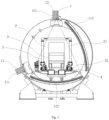
Fig. 1 is a structure diagram of a radiation inspection system in embodiments of the present disclosure. -
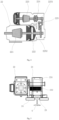
Figs. 2 to 4 are working principle diagrams of a primary-secondary motor. -
Fig. 5 is a connecting structure diagram of a primary-secondary motor and a conveying device main body in embodiments of the present disclosure. -
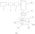
Fig. 6 is a control principle diagram of a radiation inspection system in embodiments of the present disclosure. - Technical solutions in the embodiments of the present disclosure will be described below clearly and completely in conjunction with the accompanying drawings in the embodiments of the present disclosure. Obviously, the described embodiments are only part of, instead of all of the embodiments of the present disclosure. The following description of at least one exemplary embodiment is actually only illustrative, and in no way serves as any limitation on the present disclosure and its application or use. Based on the embodiments in the present disclosure, all of other embodiments obtained by those of ordinary skill in the art without creative work should fall into the protection scope of the present disclosure.
- Unless specifically stated otherwise, the relative arrangement of components and steps, numerical expressions and numerical values set forth in these embodiments do not limit the scope of the present disclosure. Furthermore, it should be appreciated that, for ease of description, the sizes of various parts shown in the drawings are not drawn in accordance with actual proportional relationships. Technologies, methods, and devices known to those of ordinary skill in the related art may be not discussed in detail, but where appropriate, the technologies, methods, and equipment should be regarded as part of the specification as granted. In all examples shown and discussed here, any specific value should be interpreted as merely exemplary, rather than as a limitation. Therefore, other examples of an exemplary embodiment may have different values. It should be noted that similar reference numerals and letters denote similar items in the following drawings, so once a certain item is defined in one drawing, it does not need to be further discussed in subsequent drawings.
- In the description of the present disclosure, it should be understood that the use of terms such as "first" and "second" to define parts and components is only for the convenience of distinguishing the corresponding parts and components. Unless otherwise stated, the above terms have no special meanings, and therefore cannot be construed as limitations on the protection scope of the present disclosure.
- In description of the present disclosure, it should be understood that orientation or position relations denoted by terms such as "front", "rear", "upper", "lower", "left", "right", "transverse", "longitudinal", "vertical", "horizontal", "top" and "bottom" are generally orientation or position relations illustrated based on the drawings, and are merely for the convenience of describing the present disclosure and simplifying description, and unless stated to the contrary, such terms do not indicate or imply the denoted devices or elements must have specific orientations or be constructed and operated in specific orientations, and thus cannot be construed as limiting the protection scope of the present disclosure; and orientation terms "inner" and "outer" refer to the inside and outside with respect to the contour of each component itself.
- As shown in
Figs. 1 to 6 , embodiments of the present disclosure provide a radiation inspection system. The radiation inspection system mainly includes aradiation imaging device 1, aconveying device 2 and acontroller 3. - The
radiation imaging device 1 includes at least one radiation source and at least one detector module, has a CT inspection mode and a DR inspection mode, and is configured to perform radiation inspection on an object to be inspected O passing through an inspection channel P. - The conveying
device 2 includes a conveying devicemain body 21, and a primary-secondary motor 22 in drive connection with the conveying devicemain body 21 to drive the conveying devicemain body 21 to move along the inspection channel P. The primary-secondary motor 22 includes amain motor 221, a sub-motor 223, and aspeed reducer 225. The conveyingdevice 2 may be, for example, a self-travelling conveying device, a plate chain conveying device, a belt conveying device, or the like. - The
controller 3 is in signal connection with theradiation imaging device 1 and the primary-secondary motor 22, and thecontroller 3 is configured such that when theradiation imaging device 1 is in the CT inspection mode, the conveying devicemain body 21 is in drive connection with the sub-motor 223 through thespeed reducer 225 to convey the object to be inspected O under the drive of the sub-motor 223, and in the DR inspection mode, the conveying devicemain body 21 is in drive connection with themain motor 221 to convey the object to be inspected O under the drive of themain motor 221, wherein a conveying speed when the conveying devicemain body 21 is in drive connection with themain motor 221 is higher than a conveying speed when the conveying device main body is in drive connection with the sub-motor 223. - The
controller 3 may be embodied as a general-purpose processor, a programmable logic controller (PLC), a digital signal processor (DSP), an application specific integrated circuit (ASIC), a field-programmable gate array (FPGA) or other programmable logic device, a discrete gate or transistor logic device, a discrete hardware component, or any appropriate combination thereof, for performing functions described in the present disclosure. - According to the radiation inspection system in embodiments of the present disclosure, the DR inspection technology and the CT inspection technology are used in combination, and the primary-
secondary motor 22 is in drive connection with the conveying devicemain body 21, and the primary-secondary motor 22 combines themain motor 221 and the sub-motor 223 into a whole through thespeed reducer 225, so that the primary-secondary motor 22 has a large speed difference between a speed when themain motor 221 is used for driving and a speed when the sub-motor 223 is used for driving in the process of conveyance and positioning of the conveyingdevice 2. Themain motor 221 and the sub-motor 223 of the primary-secondary motor 22 can be respectively matched with the DR inspection mode and the CT inspection mode of the radiation inspection system, and good matching between a scanning speed and a conveying speed can be achieved directly by a matching relationship between themain motor 221 and the sub-motor 223 of the primary-secondary motor 22 and the DR inspection mode and the CT inspection mode, so the control of the conveying device can be simplified and the cost can be saved. - Embodiments of the present disclosure are further described below in conjunction with
Figs. 1 to 6 . - As shown in
Figs. 1 to 6 , embodiments of the present disclosure are described by using a large radiation inspection system for radiation inspection of objects to be inspected O, such as vehicles, containers, and the like, commonly used in sectors such as customs and railroad systems. In the following description, an object to be inspected 0 is specifically a vehicle to be inspected. - As shown in
Figs. 1 to 6 , embodiments of the present disclosure provide a radiation inspection system. The radiation inspection system includes aradiation imaging device 1, a conveyingdevice 2, acontroller 3, atrack 4, and amode detecting device 5. - The
radiation imaging device 1 has the CT inspection mode and the DR inspection mode, and is configured to perform radiation inspection on an object to be inspected O passing through an inspection channel P. During radiation inspection of a vehicle to be inspected, the vehicle to be inspected passes through a scanning area in the inspection channel P under the traction of the conveyingdevice 2, thereby scanning and imaging goods, such as containers, on the vehicle to be inspected so as to perform radiation inspection on the goods on the vehicle to be inspected. A scanning speed when the radiation inspection system in the DR inspection mode as compared with the CT inspection mode is much higher than a scanning speed when the radiation inspection system is in the CT inspection mode. To accomplish continuous scanning, the conveyingdevice 2 has an ability to tow the vehicle to be inspected smoothly in a wide range of speeds. In the present embodiments, the ratio of the highest conveying speed to the lowest conveying speed of the conveyingdevice 2 is about 50. - In embodiments of the present disclosure, as shown in
Fig. 1 , theradiation imaging device 1 includes aCT imaging part 11 and aDR imaging part 12. TheCT imaging part 11 includes afirst radiation source 111 and afirst detector module 112 disposed corresponding to thefirst radiation source 111. TheDR imaging part 12 includes asecond radiation source 121 and asecond detector module 122 disposed corresponding to thesecond radiation source 121. That is, at least one radiation source includes afirst radiation source 111 and asecond radiation source 121, and at least one detector module includes afirst detector module 112 and asecond detector module 122. The CT imaging part may, for example, be configured as a CT imaging part with a single energy output or multiple energy outputs. - In embodiments not illustrated, the
radiation imaging device 1 may include one radiation source and one detector module corresponding to the radiation source. The radiation source and the detector module switch between the DR inspection mode and the CT inspection mode. That is, theradiation imaging device 1 only includes one imaging part, which can switch between the DR inspection mode and the CT inspection mode. In the CT inspection mode, the radiation source and the detector module of the imaging part rotate, and the conveyingdevice 2 conveys the object to be inspected O at a slow speed. In the DR imaging mode, the radiation source and the detector module of the imaging part are motionless, and the conveyingdevice 2 conveys the object to be inspected O at a fast speed. - Besides, the
radiation imaging device 1 may also include three or more imaging parts. For example, in the case where the CT imaging part and the DR imaging part are provided respectively, it is not excluded that two independent DR imaging parts may be provided to inspect the object to be inspected O from different view angles. - The use of the DR inspection mode and the CT inspection mode may be switched according to radiation inspection needs. For example, for each vehicle to be inspected, scanning inspection can be first performed in the DR inspection mode to obtain a scanning image, then whether there is suspected prohibited goods is determined based on the scanning image, and if there is suspected prohibited goods, it also needs to determine the location of the suspected prohibited goods in the vehicle to be inspected. For a vehicle to be inspected that does not have suspected prohibited goods, it can be released directly after scanning inspection is completed. For a scanned vehicle with suspected prohibited goods, the location in the vehicle to be inspected where the suspected prohibited goods are located is subjected to scanning inspection in the CT inspection mode to make more accurate judgment. This is conducive to ensuring both inspection efficiency and accuracy degree for the DR inspection mode and the CT inspection mode.
- As shown in
Figs. 1 to 6 , the conveyingdevice 2 includes a conveying devicemain body 21, a primary-secondary motor 22, adriving wheel 23, a limitingwheel 24, afrequency converter 25, and aswitching device 26. - The primary-
secondary motor 22 is in drive connection with the conveying devicemain body 21 to drive the conveying devicemain body 21 to move along the inspection channel P. The primary-secondary motor 22 includes amain motor 221, a first connectingpart 222, a sub-motor 223, a second connectingpart 224, and aspeed reducer 225. - The first connecting
part 222 and the second connectingpart 224 each include two transmission parts having an axially connected state and an axially separated state, respectively. In the present embodiments, the first connectingdevice 222 may, for example, be a clutch. For the clutch, the two transmission parts are two components of the clutch that clutch each other. The second connectingpart 224 may, for example, be a coupling. For the coupling, the two transmission parts are two shaft connecting parts of the coupling. - As shown in
Figs. 2 to 4 , thespeed reducer 225 has aninput shaft 2251 and anoutput shaft 2252. Themain motor 221 is connected to theoutput shaft 2252 via the first connectingpart 222. The sub-motor 223 is connected to theinput shaft 2251 via the second connectingpart 224. The primary-secondary motor 22 is in drive connection with the conveying devicemain body 21 by means of themain motor 221. - In embodiments not illustrated, the first connecting
part 222 may be in a form other than a clutch, such as a coupling, and the second connectingpart 224 may be in a form other than a coupling, such as a clutch. - As shown in
Fig. 2 to 4 , the primary-secondary motor 22 is a composite motor combining the higher-powermain motor 221 with the lower-power sub-motor 223 by thespeed reducer 225 to obtain an ultra-wide speed ratio. - As shown in
Fig. 2 , when themain motor 221 is powered on and works, the sub-motor 223 is not power on and is in a braking state, the two transmission parts of the first connectingpart 222 are in the axially separated state, the two transmission parts of the second connectingpart 224 are also in the axially separated state, and thespeed reducer 225 does not work, and at that time, a main shaft of themain motor 221 outputs a high speed. The primary-secondary motor in a working state shown inFig. 2 corresponds to the DR scanning mode. - As shown in
Fig. 3 , when the sub-motor 223 is powered on and works, themain motor 221 is not powered on, the two transmission parts of the first connectingpart 222 are in the axially connected state, the two transmission parts of the second connectingpart 224 are also in the axially connected state, the sub-motor 223 causes, through thespeed reducer 225, themain motor 221 to rotate, the primary-secondary motor 22 relies on the sub-motor 223 for driving, and after the power of the sub-motor 223 is transmitted to a rotating shaft of themain motor 221 through thespeed reducer 225, the rotating shaft of themain motor 221 outputs a low and smooth rotating speed. The primary-secondary motor in the working state shown inFig. 3 corresponds to the CT scanning mode. - As shown in
Fig. 4 , the sub-motor 223 is in the braking state, themain motor 221 is in the braking state, the two transmission parts of the first connectingpart 222 are in the axially connected state, the two transmission parts of the second connectingpart 224 are in the axially separated state, and both themain motor 221 and the sub-motor 223 are inactive. - The
controller 3 is in signal connection with theradiation imaging device 1 and the primary-secondary motor 22, and thecontroller 3 is configured such that when theradiation imaging device 1 is in the CT inspection mode, the conveying devicemain body 21 is in drive connection with the sub-motor 223 through thespeed reducer 225, and no power is output from themain motor 221 to the conveying devicemain body 21; and in the DR inspection mode, the conveying devicemain body 21 is in drive connection with themain motor 221, and no power is output from the sub-motor 223 to the conveying devicemain body 21. - According to the above description, it can be seen that in embodiments of the present disclosure, by switching the states of the
main motor 221 and the sub-motor 223 in the primary-secondary motor 22, the primary-secondary motor 22 can obtain an ultra-wide speed ratio, and achieve precise positioning, and a constant speed during low-speed operation, and is not liable to be affected by the load. After the primary-secondary motor 22 is drive connected to the conveying devicemain body 21, themain motor 221 and the sub-motor 223 of the primary-secondary motor 22 can be respectively matched with the DR inspection mode and the CT inspection mode of the radiation inspection system that adopts the DR inspection technology and the CT inspection technology in combination, so that good matching between a scanning speed and a conveying speed can be achieved directly by a matching relationship between themain motor 221 and the sub-motor 223 of the primary-secondary motor 22 and the DR inspection mode and the CT inspection mode, so the control of the conveying device can be simplified and the cost can be saved. - The use of the primary-
secondary motor 22 in the radiation inspection system as a power source for driving the conveyingdevice 2 achieves high positioning precision, and allows a high load weight, and frequent startup per unit of time. Moreover, the primary-secondary motor 22 has good performance such as anti-vibration and high temperature resistance. Since themain motor 221 uses a clutch for braking, the primary-secondary motor 22 and transmission components can be protected from damage if the conveying path is uneven during a traveling process, such as when it needs to cross a gap of thetrack 4, during conveyance of the object to be inspected O by the conveyingdevice 2, and thus the structure of the conveyingdevice 2 is robust and durable, simple and easy to implement, and its environmental adaptability is strong. - As shown in
Fig. 6 , thecontroller 3 is configured to receive a working mode signal of theradiation imaging device 1 and generate a control command according to the working mode signal. The working mode signal indicates theradiation imaging device 1 is in the CT inspection mode or the DR inspection mode. - The
frequency converter 25 is configured to be in signal connection with the controller, to receive the control command and adjust an output parameter according to the control command. - The switching
device 26 is electrically connected to thefrequency converter 25 and is configured to selectively electrically connect thefrequency converter 25 to one of themain motor 221 and the sub-motor 223. The switchingdevice 26 includes, for example, an electrical switch or a relay, or the like. - The
frequency converter 25 may identify themain motor 221 and the sub-motor 223 of the primary-secondary motor 22, respectively, establish an optimized control model, and store a plurality of parameter sets. Each parameter set includes a plurality of parameters. The plurality of parameters include, for example, a power, a current, voltage, a rotation speed, and a maximum frequency of the motor. Thefrequency converter 25 can call a parameter set matching themain motor 221 or the sub-motor 223 that is currently electrically connected thereto, according to the control command. When themain motor 221 needs to be used, thefrequency converter 25 is switched by the switchingdevice 26 to be electrically connected to themain motor 221, and the parameter set is switched to a parameter set matching themain motor 221; and when the sub-motor 223 needs to be used, thefrequency converter 25 is switched to be electrically connected to the sub-motor 223, and the parameter set is switched to a parameter set matching the sub-motor 223. Providing thefrequency converter 25 and theswitching device 26 is conducive to ensuring that a drive system always meets project needs with a suitable power output. Moreover, the use of one frequency converter and one set of switching device for controlling operation of the primary-secondary motor 22 is conducive to reducing a cabinet volume and saving costs. - The
mode detecting device 5 is in signal connection with theradiation imaging device 1 and thecontroller 3, and themode detecting device 5 is configured to monitor working parameters of theradiation imaging device 1 and transmit the working parameters as a working mode signal to thecontroller 3. Themode detecting device 5 includes, for example, a voltage detecting device, a current detecting device, a photoelectric sensor, or the like for monitoring whether the radiation source of the imaging part of theradiation imaging device 1 is activated. - In embodiments not illustrated, the
mode detecting device 5 is not indispensable. For example, thecontroller 3 may identify the inspection mode of the radiation imaging device by directly receiving a control command that controls the activation of the imaging part. - As shown in
Figs. 1 and5 , in the present embodiments, the conveyingdevice 2 is a self-travelling conveying device. The self-travelling conveying device includes adriving wheel 23 connected to the conveying devicemain body 21, and the primary-secondary motor 22 is in drive connection with thedriving wheel 23. As shown inFigs. 1 and5 , the conveying devicemain body 21 includes a portal frame structure. The portal frame structure includes a cross beam and two vertical beams connected to two ends of the cross beam. A plurality of drivingwheels 23 are respectively provided at the bottoms of the two vertical beams to carry the portal frame structure and cause the portal frame structure to travel. - When the vehicle to be inspected is conveyed, the primary-
secondary motor 22 is in drive connection with thedriving wheel 23 to cause the portal frame structure to travel. The vehicle to be inspected is located within the space enclosed by the portal frame structure and the ground and is connected to the portal frame structure, and travels synchronously with the portal frame structure in the inspection channel P. - The number of the primary-
secondary motor 22 may be configured according to an output power of the primary-secondary motor 22 and a driving force required for the conveyingdevice 2. For example, in the present embodiments, three primary-secondary motors 22 are configured corresponding to each vertical beam, and each primary-secondary motor 22 is correspondingly in drive connection with onedriving wheel 23. - As shown in
Figs. 1 and5 , the radiation inspection system further includes atrack 4, and thedriving wheel 23 is located on thetrack 4. The conveyingdevice 2 further includes a limitingwheel 24. The limitingwheel 24 cooperates with a lateral side of thetrack 4. - As shown in
Fig. 6 , a housing of the primary-secondary motor 22 is fixedly connected to the conveying devicemain body 21, and a connectingshaft 232 of thedriving wheel 23 is rotatably connected to the conveying devicemain body 21 and connected to the rotating shaft of themaster motor 221 of the primary-secondary motor 22. Awheel body 231 of thedriving wheel 23 is provided on the connectingshaft 232 and is located on an upper surface of thetrack 4. Limitingwheels 24 are respectively provided on two sides below a lower edge of thedriving wheel 23, and a spacing is formed between the limitingwheels 24 on the two sides, and at least a portion of thetrack 4 is located in the spacing. In this way, the limitingwheels 24 can prevent thedriving wheel 23 from disengaging from thetrack 4. - In embodiments of the present disclosure, the primary-
secondary motor 22 drives thedriving wheel 23, thereby driving the conveyingdevice 2 to travel along the inspection channel P. The primary-secondary motor 22 and thedriving wheel 23 may be designed as a modular traveling unit to achieve drive connection with the conveying devicemain body 21 that transports the vehicle to be inspected. The conveyingdevice 2 is configured with a suitable number of traveling units so that its carrying capacity can meet the needs of vehicles to be inspected of different weights. - In the radiation inspection system of embodiments of the present disclosure, the conveying device has a simple and reliable structure, is flexible and convenient to control, has a low maintenance cost, and can convey vehicles to be inspected of different weights to accomplish scanning inspection in the DR inspection mode and scanning inspection in the CT inspection mode.
- Finally, it should be noted that the above embodiments are only used for describing rather than limiting the technical solutions of the present disclosure. Although the present disclosure is described in detail with reference to the preferred embodiments, those of ordinary skill in the art should understand that they still can make modifications to the specific implementations in the present disclosure or make equivalent substitutions to part of technical features thereof; and such modifications and equivalent substitutions should be encompassed within the technical solutions sought for protection in the present disclosure.
Claims (8)
- A radiation inspection system, comprising:a radiation imaging device (1), which comprises at least one radiation source (111, 121) and at least one detector module (121, 122), has a CT inspection mode and a DR inspection mode, and is configured to perform radiation inspection on an object to be inspected (O) passing through an inspection channel (P);a conveying device (2), which comprises a conveying device main body (21), and a primary-secondary motor (22) in drive connection with the conveying device main body (21) to drive the conveying device main body (21) to move along the inspection channel (P), the primary-secondary motor (22) including a main motor (221), a sub-motor (223), and a speed reducer (225); anda controller (3) in signal connection with the radiation imaging device (1) and the primary-secondary motor (22), the controller (3) being configured such that when the radiation imaging device (1) is in the CT inspection mode, the conveying device main body (21) is in drive connection with the sub-motor (223) through the speed reducer (225) to convey the object to be inspected (O) under the drive of the sub-motor (223), and in the DR inspection mode, the conveying device main body (21) is in drive connection with the main motor (221) to convey the object to be inspected (O) under the drive of the main motor (221), wherein a conveying speed when the conveying device main body (21) is in drive connection with the main motor (221) is higher than a conveying speed when the conveying device main body (21) is in drive connection with the sub-motor (223).
- The radiation inspection system according to claim 1, whereinthe controller (3) is configured to receive a working mode signal of the radiation imaging device (1) and generate a control command according to the working mode signal, the working mode signal indicating the radiation imaging device (1) is in the CT inspection mode or the DR inspection mode; andthe conveying device (2) further comprises a frequency converter (25) and a switching device (26), wherein the frequency converter (25) is configured to be in signal connection with the controller, to receive the control command and adjust an output parameter according to the control command, and the switching device (26) is electrically connected to the frequency converter (25) and is configured to selectively electrically connect the frequency converter (25) to one of the main motor (221) and the sub-motor (223).
- The radiation inspection system according to claim 1 or 2, further comprising a mode detecting device (5), wherein the mode detecting device (5) is in signal connection with the radiation imaging device (1) and the controller (3), and the mode detecting device (5) is configured to monitor working parameters of the radiation imaging device (1) and transmit the working parameters as a working mode signal to the controller (3).
- The radiation inspection system according to any one of claims 1-3, wherein the radiation imaging device (1) comprises:a CT imaging part (11), which comprises a first radiation source (111) and a first detector module (121) disposed corresponding to the first radiation source (111); anda DR imaging part (12), which comprises a second radiation source (121) and a second detector module (122) disposed corresponding to the second radiation source (121).
- The radiation inspection system according to any one of claims 1-4, wherein the radiation imaging device (1) comprises one radiation source and one detector module corresponding to the radiation source, and the radiation source and the detector module switch between the DR inspection mode and the CT inspection mode.
- The radiation inspection system according to any one of claims 1-5, wherein the conveying device (2) comprises a self-travelling conveying device, wherein the self-travelling conveying device comprises a driving wheel (23) connected to the conveying device main body (21), and the primary-secondary motor (22) is in drive connection with the driving wheel (23).
- The radiation inspection system according claim 6, further comprising a track (4), and the driving wheel (23) is located on the track (4); and the conveying device (2) further comprises a limiting wheel (24), the limiting wheel (24) cooperates with a lateral side of the track (4).
- The radiation inspection system according to any one of claims 1-7, wherein the primary-secondary motor (22) further comprises a first connecting part (222) and a second connecting part (224), wherein the first connecting part (222) and the second connecting part (224) each comprises two transmission parts having an axially connected state and an axially separated state, respectively; the speed reducer (225) has an input shaft (2251) and an output shaft (2252); the main motor (221) is connected to the output shaft (2252) via the first connecting part (222); the sub-motor (223) is connected to the input shaft (2251) via the second connecting part (224); and the primary-secondary motor (22) is in drive connection with the conveying device main body (21) by means of the main motor (221).
Applications Claiming Priority (2)
| Application Number | Priority Date | Filing Date | Title |
|---|---|---|---|
| CN202111661865.9A CN116223535A (en) | 2021-12-30 | 2021-12-30 | Radiation inspection system |
| PCT/CN2022/142633 WO2023125612A1 (en) | 2021-12-30 | 2022-12-28 | Radiation inspection system |
Publications (2)
| Publication Number | Publication Date |
|---|---|
| EP4459270A1 true EP4459270A1 (en) | 2024-11-06 |
| EP4459270A4 EP4459270A4 (en) | 2026-01-07 |
Family
ID=86571820
Family Applications (1)
| Application Number | Title | Priority Date | Filing Date |
|---|---|---|---|
| EP22914864.8A Pending EP4459270A4 (en) | 2021-12-30 | 2022-12-28 | RADIATION INSPECTION SYSTEM |
Country Status (3)
| Country | Link |
|---|---|
| EP (1) | EP4459270A4 (en) |
| CN (1) | CN116223535A (en) |
| WO (1) | WO2023125612A1 (en) |
Family Cites Families (28)
| Publication number | Priority date | Publication date | Assignee | Title |
|---|---|---|---|---|
| DE1212867B (en) * | 1963-08-16 | 1966-03-17 | Duesterloh Fabrik Fuer Bergwer | Drive for a conveyor especially intended for mining |
| US5638420A (en) * | 1996-07-03 | 1997-06-10 | Advanced Research And Applications Corporation | Straddle inspection system |
| KR200247911Y1 (en) * | 1999-03-31 | 2001-10-27 | 윤종용 | Apparatus for transmitting power of scanner |
| US6878941B2 (en) * | 2002-04-09 | 2005-04-12 | Elgems Ltd. | Gamma camera and CT system |
| CN2419218Y (en) * | 2000-02-03 | 2001-02-14 | 山西经纬合力机械制造公司总厂 | Main spindle of comber |
| CN2537859Y (en) * | 2002-04-26 | 2003-02-26 | 陈苏琦 | Double gear box combined speed reducer with slow transmission function |
| JP2006129975A (en) * | 2004-11-04 | 2006-05-25 | Ge Medical Systems Global Technology Co Llc | X-ray ct apparatus and x-ray ct photographing method |
| CN1916611A (en) * | 2006-09-08 | 2007-02-21 | 清华大学 | Mulriple DR/CT detection apparatus for containers |
| CN201044406Y (en) * | 2007-01-19 | 2008-04-02 | 汪洋 | Electromagnetic brake three-phase asynchronous motor with large variable speed ratio |
| CN101936924B (en) * | 2009-06-30 | 2012-07-04 | 同方威视技术股份有限公司 | Article inspection system |
| CN201637698U (en) * | 2009-12-25 | 2010-11-17 | 同方威视技术股份有限公司 | A workpiece carrying motion device |
| JP5864182B2 (en) * | 2011-09-28 | 2016-02-17 | テルモ株式会社 | Motor drive device and diagnostic imaging device |
| CN103640469A (en) * | 2013-10-13 | 2014-03-19 | 金洁琼 | Dual-motor automatic speed changing transmission mechanism |
| CN104773465B (en) * | 2014-01-14 | 2017-02-15 | 深圳市汇拓新邦科技有限公司 | Large-scale transmission master-slave control equipment of belt conveyer and operation method thereof |
| CN108445546A (en) * | 2014-05-15 | 2018-08-24 | 北京君和信达科技有限公司 | A kind of list source bimodulus speed general formula movement target emanation inspection system and method |
| CN105125232B (en) * | 2015-09-28 | 2019-01-15 | 中国科学院苏州生物医学工程技术研究所 | CT scanner with DR film making function |
| CN205141950U (en) * | 2015-10-30 | 2016-04-06 | 南京起重电机总厂 | Primary and secondary formula double speed toper rotor three -phase asynchronous motor |
| CN106667510A (en) * | 2016-06-08 | 2017-05-17 | 张金山 | Cerebral CT three-dimensional imaging device |
| US11192742B2 (en) * | 2017-10-26 | 2021-12-07 | Canon Kabushiki Kaisha | Sheet conveyance apparatus and image forming apparatus |
| CN108254397B (en) * | 2017-12-12 | 2021-03-05 | 北京航星机器制造有限公司 | Luggage article safety inspection device and inspection method thereof |
| CN110460266A (en) * | 2018-05-06 | 2019-11-15 | 西北农林科技大学 | Bi-motor cooperates with conveying control device |
| CN108542413A (en) * | 2018-05-09 | 2018-09-18 | 清华大学 | CT examination system |
| US11039808B2 (en) * | 2019-02-13 | 2021-06-22 | Analogic Corporation | Scanning systems configured to inspect conveyed objects and related systems and methods |
| CN109932374B (en) * | 2019-04-03 | 2024-01-05 | 天津三英精密仪器股份有限公司 | Device with CT and DR dual-function imaging detection |
| CN209705217U (en) * | 2019-10-11 | 2019-11-29 | 江苏国茂减速机股份有限公司 | A kind of main and assist driving gearbox drive structure |
| CN211329855U (en) * | 2019-11-29 | 2020-08-25 | 江苏云宇医疗科技有限公司 | Positioning motor |
| CN211627844U (en) * | 2020-03-11 | 2020-10-02 | 合肥赛英迪光电科技有限公司 | Double-source double-visual-angle X-ray channel type security inspection machine with novel structure |
| CN113659890B (en) * | 2021-08-18 | 2024-07-30 | 歌尔股份有限公司 | Motor control system and conveying line |
-
2021
- 2021-12-30 CN CN202111661865.9A patent/CN116223535A/en active Pending
-
2022
- 2022-12-28 EP EP22914864.8A patent/EP4459270A4/en active Pending
- 2022-12-28 WO PCT/CN2022/142633 patent/WO2023125612A1/en not_active Ceased
Also Published As
| Publication number | Publication date |
|---|---|
| US20250035568A1 (en) | 2025-01-30 |
| EP4459270A4 (en) | 2026-01-07 |
| WO2023125612A1 (en) | 2023-07-06 |
| CN116223535A (en) | 2023-06-06 |
Similar Documents
| Publication | Publication Date | Title |
|---|---|---|
| CN204009577U (en) | Intelligent carriage combined type obstacle avoidance system | |
| EP1962056B1 (en) | Direction correcting apparatus, method thereof and movable radiation inspecting system | |
| CN209940384U (en) | AGV dolly | |
| CN103420310B (en) | Driverless operation electric forward formula embraces car | |
| CN106515900A (en) | AGV mobile device | |
| US10782246B2 (en) | Movable ray inspection system and ray inspection method for a container | |
| US20250035568A1 (en) | Radiation inspection system | |
| CN215180850U (en) | Radar angular resolution test system | |
| US20170113608A1 (en) | System and method for operating a machine | |
| CN105856188A (en) | Movable detection robot for flexible building structure | |
| CN201569413U (en) | Automatic dynamic dimension measurement device for motor vehicle rear overhang | |
| CN108840009B (en) | Mobile intelligent warehouse | |
| CN206436927U (en) | AGV collision avoidance sensing devices | |
| KR101586926B1 (en) | Equipped with sensing controls of the power module and the truck width and a driving method thereof | |
| KR101660361B1 (en) | Mine Detection Sensor Device for Mine Detector of Vehicle | |
| US20220073329A1 (en) | Transport device, control method, and computer program product | |
| CN209721027U (en) | It is adapted to the flexible conveyer belt traction chassis of container | |
| CN215217574U (en) | Modular highway tunnel deformation detection AGV trolley based on ground penetrating radar | |
| CN202305798U (en) | Double-ultrasonic-probe scanning detection crashproof apparatus for port machine | |
| CN209396831U (en) | A kind of Intelligent carrier | |
| CN209167899U (en) | A kind of double belt carrying navigation vehicles | |
| CN221115707U (en) | Tooling vehicle for feeding and discharging of slicing machine | |
| CN212541660U (en) | Cargo handling evaluation device applied to forklift test | |
| CN215923551U (en) | Adjustable laser assembly for detecting tearing of conveying belt | |
| CN111319625A (en) | Vehicle travel control system, vehicle, traction system, and vehicle travel control method |
Legal Events
| Date | Code | Title | Description |
|---|---|---|---|
| STAA | Information on the status of an ep patent application or granted ep patent |
Free format text: STATUS: THE INTERNATIONAL PUBLICATION HAS BEEN MADE |
|
| PUAI | Public reference made under article 153(3) epc to a published international application that has entered the european phase |
Free format text: ORIGINAL CODE: 0009012 |
|
| STAA | Information on the status of an ep patent application or granted ep patent |
Free format text: STATUS: REQUEST FOR EXAMINATION WAS MADE |
|
| 17P | Request for examination filed |
Effective date: 20240529 |
|
| AK | Designated contracting states |
Kind code of ref document: A1 Designated state(s): AL AT BE BG CH CY CZ DE DK EE ES FI FR GB GR HR HU IE IS IT LI LT LU LV MC ME MK MT NL NO PL PT RO RS SE SI SK SM TR |
|
| DAV | Request for validation of the european patent (deleted) | ||
| DAX | Request for extension of the european patent (deleted) | ||
| A4 | Supplementary search report drawn up and despatched |
Effective date: 20251208 |
|
| RIC1 | Information provided on ipc code assigned before grant |
Ipc: G01N 23/04 20180101AFI20251202BHEP Ipc: G01N 23/046 20180101ALI20251202BHEP Ipc: G01V 5/226 20240101ALI20251202BHEP |