EP4459249A1 - Nahfeldmessvorrichtung und -verfahren für schallbasierte uhrenherstellung - Google Patents
Nahfeldmessvorrichtung und -verfahren für schallbasierte uhrenherstellung Download PDFInfo
- Publication number
- EP4459249A1 EP4459249A1 EP24170087.1A EP24170087A EP4459249A1 EP 4459249 A1 EP4459249 A1 EP 4459249A1 EP 24170087 A EP24170087 A EP 24170087A EP 4459249 A1 EP4459249 A1 EP 4459249A1
- Authority
- EP
- European Patent Office
- Prior art keywords
- microphones
- measuring device
- watchmaking
- supporting surface
- noise
- Prior art date
- Legal status (The legal status is an assumption and is not a legal conclusion. Google has not performed a legal analysis and makes no representation as to the accuracy of the status listed.)
- Pending
Links
Images







Classifications
-
- G—PHYSICS
- G01—MEASURING; TESTING
- G01H—MEASUREMENT OF MECHANICAL VIBRATIONS OR ULTRASONIC, SONIC OR INFRASONIC WAVES
- G01H3/00—Measuring characteristics of vibrations by using a detector in a fluid
- G01H3/10—Amplitude; Power
-
- G—PHYSICS
- G01—MEASURING; TESTING
- G01H—MEASUREMENT OF MECHANICAL VIBRATIONS OR ULTRASONIC, SONIC OR INFRASONIC WAVES
- G01H3/00—Measuring characteristics of vibrations by using a detector in a fluid
- G01H3/04—Frequency
-
- G—PHYSICS
- G01—MEASURING; TESTING
- G01N—INVESTIGATING OR ANALYSING MATERIALS BY DETERMINING THEIR CHEMICAL OR PHYSICAL PROPERTIES
- G01N29/00—Investigating or analysing materials by the use of ultrasonic, sonic or infrasonic waves; Visualisation of the interior of objects by transmitting ultrasonic or sonic waves through the object
- G01N29/14—Investigating or analysing materials by the use of ultrasonic, sonic or infrasonic waves; Visualisation of the interior of objects by transmitting ultrasonic or sonic waves through the object using acoustic emission techniques
-
- G—PHYSICS
- G01—MEASURING; TESTING
- G01N—INVESTIGATING OR ANALYSING MATERIALS BY DETERMINING THEIR CHEMICAL OR PHYSICAL PROPERTIES
- G01N29/00—Investigating or analysing materials by the use of ultrasonic, sonic or infrasonic waves; Visualisation of the interior of objects by transmitting ultrasonic or sonic waves through the object
- G01N29/22—Details, e.g. general constructional or apparatus details
- G01N29/30—Arrangements for calibrating or comparing, e.g. with standard objects
-
- G—PHYSICS
- G04—HOROLOGY
- G04D—APPARATUS OR TOOLS SPECIALLY DESIGNED FOR MAKING OR MAINTAINING CLOCKS OR WATCHES
- G04D7/00—Measuring, counting, calibrating, testing or regulating apparatus
- G04D7/12—Timing devices for clocks or watches for comparing the rate of the oscillating member with a standard
- G04D7/1207—Timing devices for clocks or watches for comparing the rate of the oscillating member with a standard only for measuring
- G04D7/1235—Timing devices for clocks or watches for comparing the rate of the oscillating member with a standard only for measuring for the control mechanism only (found from outside the clockwork)
- G04D7/125—Timing devices for clocks or watches for comparing the rate of the oscillating member with a standard only for measuring for the control mechanism only (found from outside the clockwork) for measuring frequency
-
- H—ELECTRICITY
- H04—ELECTRIC COMMUNICATION TECHNIQUE
- H04R—LOUDSPEAKERS, MICROPHONES, GRAMOPHONE PICK-UPS OR LIKE ACOUSTIC ELECTROMECHANICAL TRANSDUCERS; ELECTRIC HEARING AIDS; PUBLIC ADDRESS SYSTEMS
- H04R3/00—Circuits for transducers
- H04R3/005—Circuits for transducers for combining the signals of two or more microphones
-
- G—PHYSICS
- G01—MEASURING; TESTING
- G01N—INVESTIGATING OR ANALYSING MATERIALS BY DETERMINING THEIR CHEMICAL OR PHYSICAL PROPERTIES
- G01N2291/00—Indexing codes associated with group G01N29/00
- G01N2291/02—Indexing codes associated with the analysed material
- G01N2291/025—Change of phase or condition
- G01N2291/0258—Structural degradation, e.g. fatigue of composites, ageing of oils
-
- G—PHYSICS
- G01—MEASURING; TESTING
- G01N—INVESTIGATING OR ANALYSING MATERIALS BY DETERMINING THEIR CHEMICAL OR PHYSICAL PROPERTIES
- G01N2291/00—Indexing codes associated with group G01N29/00
- G01N2291/10—Number of transducers
- G01N2291/106—Number of transducers one or more transducer arrays
-
- G—PHYSICS
- G01—MEASURING; TESTING
- G01N—INVESTIGATING OR ANALYSING MATERIALS BY DETERMINING THEIR CHEMICAL OR PHYSICAL PROPERTIES
- G01N2291/00—Indexing codes associated with group G01N29/00
- G01N2291/26—Scanned objects
- G01N2291/269—Various geometry objects
- G01N2291/2698—Other discrete objects, e.g. bricks
-
- H—ELECTRICITY
- H04—ELECTRIC COMMUNICATION TECHNIQUE
- H04R—LOUDSPEAKERS, MICROPHONES, GRAMOPHONE PICK-UPS OR LIKE ACOUSTIC ELECTROMECHANICAL TRANSDUCERS; ELECTRIC HEARING AIDS; PUBLIC ADDRESS SYSTEMS
- H04R1/00—Details of transducers, loudspeakers or microphones
- H04R1/02—Casings; Cabinets ; Supports therefor; Mountings therein
-
- H—ELECTRICITY
- H04—ELECTRIC COMMUNICATION TECHNIQUE
- H04R—LOUDSPEAKERS, MICROPHONES, GRAMOPHONE PICK-UPS OR LIKE ACOUSTIC ELECTROMECHANICAL TRANSDUCERS; ELECTRIC HEARING AIDS; PUBLIC ADDRESS SYSTEMS
- H04R1/00—Details of transducers, loudspeakers or microphones
- H04R1/08—Mouthpieces; Microphones; Attachments therefor
-
- H—ELECTRICITY
- H04—ELECTRIC COMMUNICATION TECHNIQUE
- H04R—LOUDSPEAKERS, MICROPHONES, GRAMOPHONE PICK-UPS OR LIKE ACOUSTIC ELECTROMECHANICAL TRANSDUCERS; ELECTRIC HEARING AIDS; PUBLIC ADDRESS SYSTEMS
- H04R1/00—Details of transducers, loudspeakers or microphones
- H04R1/20—Arrangements for obtaining desired frequency or directional characteristics
- H04R1/32—Arrangements for obtaining desired frequency or directional characteristics for obtaining desired directional characteristic only
- H04R1/40—Arrangements for obtaining desired frequency or directional characteristics for obtaining desired directional characteristic only by combining a number of identical transducers
- H04R1/406—Arrangements for obtaining desired frequency or directional characteristics for obtaining desired directional characteristic only by combining a number of identical transducers microphones
-
- H—ELECTRICITY
- H04—ELECTRIC COMMUNICATION TECHNIQUE
- H04R—LOUDSPEAKERS, MICROPHONES, GRAMOPHONE PICK-UPS OR LIKE ACOUSTIC ELECTROMECHANICAL TRANSDUCERS; ELECTRIC HEARING AIDS; PUBLIC ADDRESS SYSTEMS
- H04R2201/00—Details of transducers, loudspeakers or microphones covered by H04R1/00 but not provided for in any of its subgroups
- H04R2201/40—Details of arrangements for obtaining desired directional characteristic by combining a number of identical transducers covered by H04R1/40 but not provided for in any of its subgroups
- H04R2201/401—2D or 3D arrays of transducers
Definitions
- the present invention relates to a device and a method for measuring characteristics of a clockwork mechanism of a mechanical watch, and in particular for measuring those through an aerial sound-based measurement.
- a final quality control of the watches is carried out by measuring means, which are based on gripping the watch to be controlled in a clamp, or a similar support system, which includes a sensor such as a piezoelectric disc or an accelerometer, in direct or indirect mechanical contact with the watch.
- the vibrations from the watch which can be mechanical or deriving from sound generated in the watch, for instance by the escapement, reach the sensor through structure-borne conduction, and then the sensor converts those vibrations into an electrical signal.
- the electrical signal collected in this way is therefore an image of the vibrations of the place of contact between the watch to be examined and the sensor, or the support system.
- the electrical signal thus contains some information about the internal functioning of the watch, such as, for example, an image of the patterns of the shock trains of the escapement organ, or an image of the rattling or rubbing noise of the automatic winding mass, or in general of any organ in the watch which generates noise and/or mechanical vibrations.
- microphones are known to be placed in the near proximity of the watch and pick up sounds, which are then similarly converted into an electrical signal.
- optical measurements have been suggested.
- the electrical signal can then be advantageously analyzed by signal processing algorithms in order to extract various information concerning the internal functioning of the measured watch.
- the (far field) microphone-based approaches suffer from high self-noise and sensitivity to all environmental noises. Since manufacturing takes places in a noisy environment, it requires testing of each watch in a separate soundproof chamber, which cannot be automated and has high costs.
- optical-based approaches require a direct view of the internal organ which might always be available. In any case, they do not allow testing of the watch when closed in its final configuration.
- the vibration-based (or structure-borne conduction based) measurements are based on a piezoelectric or accelerometer sensor.
- Those sensors are built as resonant sensors, as this is the only manner to make them sensible enough to the low signals which are to be measured.
- This resonant characteristic severely limits the ability of the sensor to measure vibrations, and thus information, at frequencies different from the resonant frequency, and results in a self-noise of the sensor in those lateral frequencies.
- the vibration-based measurements suffer from a reduced detection band in the frequency spectrum. This significantly limits the amount of useful information that those measurements can obtain.
- the inventors have recognized that the near-field acoustic emission of a small object is highly variable along its external envelope and that a spatial scanning of the near-field acoustic emission procures a plurality of information that allow to better characterize the acoustic behavior and noise sources and emission of the object being in particular a mechanical watch.
- the inventors have also recognized that a microphone-based and spatial scanning-based measurement provides the best available information in terms of frequency band, as microphones have an inherently broader measuring band than vibration sensors, and also as a plurality of microphones provides the best available information from weak signals captures, as combining a plurality of signal captures inherently brings an increased signal-to-noise ratio capability.
- a plurality of microphones can be used, and their combination allows signal processing techniques which, among other advantages that will be discussed more in details below, can allow lowering the self-noise floor of the measurement.
- the plurality of microphones can be placed in close proximity of the object be measured or even in immediate contact of an acoustic inlet of a microphone, such that noise from the environment is limited in reaching the microphones and the sound from the object is measured with very high sensitivity and selectivity.
- the technology natively incorporates all the advantages and possibilities of the near-field beamforming (NFB), maximum likelihood estimation (MLE), near-field acoustic holography (NAH), statistical optimized near-field acoustic holography (SONAH), inverse boundary element methods (IBEM), and, more generally, the equivalent source reconstruction methods, the source signals separation, the time reversal methods, the retro-propagation methods, the virtual coherent and incoherent source identification methods.
- NNB near-field beamforming
- MLE maximum likelihood estimation
- NAH near-field acoustic holography
- SONAH statistical optimized near-field acoustic holography
- IBEM inverse boundary element methods
- final quality control of watch movement is carried out by measuring means based on gripping the watch to be checked in a gripper or support system - a feeler - which includes a piezoelectric disc or an accelerometer in direct or indirect contact that picks up a vibration signal from the watch.
- the electrical signal collected in this way is therefore an image of the vibrations at the point of contact between the part to be tested and the contact structure of the feeler, intended to contain some information about the internal operation of the watch, such as, for example, an image of the shock train patterns of the escapement organ, or an image of the rattling or rubbing noise of the automatic winding mass, or even of any organ which is the seat of dynamic variable forces in the watch.
- These signals can then be advantageously analysed by signal processing algorithms in order to extract all sorts of useful indicators testifying to the operation of the measured part.
- a measurement with high temporal and frequency fidelity of the information sought requires an acoustic or vibration capture solution that enables the same criterion of a signal-to-noise ratio of around 40 or 50 dB to be met, but at frequencies typically one or two decades outside that of a resonant probe, i.e. a much wider range of frequencies, for which the resonant probe becomes totally inoperative.
- the present invention offers a solution for capturing the acoustic and vibratory emissions of watches, with the ability to obtain a signal-to-noise ratio of at least 30 dB over the entire extended frequency band and, for example, broken down into four octaves of interest, typically 5-10 kHz, 10-20 kHz, 20-40 kHz, 40-80 kHz (or even wider in some cases), in a way that is easily compatible with a production line environment.
- the solution therefore enables very high-fidelity, very broad-spectrum, high-spectral-planarity reconstruction of all the potential acoustic or vibratory emissions from a watch.
- this sound capture technique makes it possible to use all signal processing techniques for weak impulsive, tonal, multi-tonal and broadband signals.
- the invention opens up the possibility, in particular through the use of signal processing techniques by coherence extraction, transfer functions, or by long-term measurements, of a qualification of the authentic acoustic or vibratory signature of a watch, i.e. a capability for traceability and automatic recognition of a part (watch-fingerprint).
- this solution makes the methods used to qualify the stability of the isochronism of watches even more effective and robust, in particular the adaptive methods, which require extremely rapid feedback from an external motorisation of the part.
- the invention By further application to the case of watch inspection, in particular through the use of near-field acoustic echography techniques, which include the possibility of modifying the acoustic radiation impedance of the source, and require the use of non-linear filtering techniques (application of phase rotations as a function of frequency, and not just a group delay as in free-field), the invention also provides the instrumental and algorithmic requirements needed to enable antenna focusing localised in a certain part of the watch, and even the ability to automatically scan the focal point.
- the entire method described is also applicable with the use of liquid or gel contact between the object to be measured and the measurement transducers, in this case replacing the microphones with hydrophones, this variant of the invention making it possible on the one hand to create an improved acoustic impedance matching condition between the external faces of the object to be measured and the sensitive part of the transducers, and on the other hand to envisage industrial measurement methods in partially or totally immersed mode.
- the invention consists of an acoustic and ultrasonic palpation of the watch, carried out through a pressure micro-cavity applied against one face of the object to be measured, and incorporating an array of miniature digital audio and ultrasonic microphones - for example from 4 to 32 MEMS microphones (or hydrophones) - matched in amplitude and phase, whose acoustic ports are spatially distributed like a planar antenna inside the cavity (or in as many micro-cavities as there are acoustic ports formed by the microphone bearing against the surface to be measured), and whose signals are processed individually and/or aggregated by a near-field acoustic antenna algorithm.
- the invention provides a solution for very high-fidelity, very broad-spectrum, very low-noise, high-spatial-resolution frequency and time auscultation in a way that can be easily adapted for all laboratory, development, production and after-sales service requirements for all types of watch.
- an aim of the present invention is to obtain a good spectral flatness.
- a Notch filter is used to obtain fairly flat or monotonous background noise.
- MEMS sensors preferably with a flat response for the signal detected, in the arrangement of the present invention in order to obtain a good spectral flatness, which is a desired result for a good measurement of the mechanical watch, which avoids using a Notch filter or other filter which flattens the signal and loose information present in this signal.
- MEMS-based microphones have a flat response because the MEMS 'rejects' resonance towards the top of the frequency spectrum, even for small components that resonates at very high frequencies (typically above 40 kHz).
- the invention is defined by the independent claims and has been developed to overcome at least one of the issues identified above.
- the dependent claims comprise further features defining further advantageous embodiments.
- An embodiment can therefore relate to a watchmaking measuring device for measuring sound generated by an object being a mechanical watch, the watchmaking measuring device comprising: a supporting surface, a plurality of microphones placed on the supporting surface, a controller connected to the plurality of microphones, wherein the controller is configured to process the output of the plurality of microphones so as to obtain one or more signals representative of the sound generated by the mechanical watch.
- the plurality of microphones can be matched in phase and amplitude.
- the plurality of microphones can be configured to have an amplitude mismatch lower than 3 dB, preferably lower than 2 dB, even more preferably lower than 1 dB, and/or the plurality of microphones can be configured to have a phase mismatch lower than 10°, preferably lower than 5°, even more preferably lower than 1°.
- the plurality of microphones can be MEMS-based microphones.
- the plurality of microphones can be separated from each other by an intra-microphone distance, the intra-microphone distance can be lower than 1/2 of a smallest wavelength to be measured by the watchmaking measuring device, preferably lower than 1/4 of the smallest wavelength, even more preferably lower than 1/8 of the smallest wavelength.
- the plurality of microphones together can cover a total distance, the total distance can be lower than a smallest wavelength to be measured by the watchmaking measuring device, preferably lower than 1/2 of the smallest wavelength.
- the plurality of microphones together can cover a total distance, the total distance can be lower than 10cm, preferably lower than 5cm, even more preferably lower than lower than 3cm.
- the plurality of microphones can comprise at least 4 microphones, preferably at least 16 microphones, even more preferably at least 32 microphones.
- the plurality of microphones can implement an acoustic antenna.
- the plurality of microphones can comprise at least 2, preferably at least 4, microphones, or at least 2, preferably at least 4, groups of microphones, wherein different microphones, or different groups of microphones, can be configured to measure sounds on different frequency ranges.
- At least two of the different frequency ranges can be contiguous.
- the different frequency ranges can have respective bandwidths, and for frequency ranges which are contiguous, the bandwidth or the higher frequency range can be double the bandwidth or the lower frequency range.
- the different frequency ranges can be each defined by a respective minimum frequency value and maximum frequency value, and a ratio of the maximum frequency value over the minimum frequency can be at least 1.1, preferably at least 1.2, even more preferably at least 1.5, and/or the ratio of the maximum frequency value over the minimum frequency can be at most 4, preferably at most 3, even more preferably at most 2.
- different frequency ranges can be higher than 5kHz, preferably higher than 2 kHz, even more preferably higher than 500Hz, and/or lower than 80 kHz, preferably lower than 120 kHz, even more preferably lower than 200 kHz.
- frequency ranges can be preferably 500 Hz to 200 kHz, preferably between 20 kHz and 50 kHz, preferably above 50 kHz, preferably above 100 kHz and preferably above 200 kHz. That is, high frequency (preferably between 20 kHz and 50 kHz, preferably more than 50 kHz, preferably more than 100 kHz, preferably more than 200 kHz) are not very present in the mechanical watch because propagation in the mechanical watch is weak for these frequencies. There is an interest in recovering them because they contain relevant information. To do this, it is necessary to be nearby the watch because of the low propagation (that is, to have a near-field measurement).
- the microphones according to the present invention are contactless is a decisive advantage for reproducibility.
- a microphone is different from a piezo resonant vibration sensor. If one presses the object to be measured against the sensor of the prior art, there will be no pick-up sound by air. There are differences between resonant pick-up (i.e solid-state transmission) sensor and airborne microphones. In watchmaking, the problem of reproducibility and broadband sensitivity comes from the choice of this type of microphone.
- the measuring operator listen in contact, he will face a problem of reproducibility/repeatability from one measurement to the next, particularly if, for example, he put the watch down and put it back on the same measuring tool: he will get two different measurements. This may actually depend on the quality of the contact (for example, whether the contact is pressed hard or lightly): this also shifts the resonance peak in frequency, at least slightly. With the flexible supporting surface of the present invention along with the overlapped opening, the problem is solved.
- a plurality of, preferably a majority of, the plurality of microphones, preferably all of them, can be capable of measuring sound in a same bandwidth
- the different frequency ranges can be defined by respective different bandpass filters, which can be configured to act on the output of the microphones.
- the controller can be configured to apply signal processing to output signals of the plurality of microphones so as to reduce noise common to the output signals.
- each of the plurality of microphones can have a self-noise level which can be higher than a minimum sound to be measured from the mechanical watch.
- the supporting surface can comprise, or can be, a printed circuit board, to which the plurality of microphones can be electrically connected.
- the plurality of microphones can be placed on a side of the supporting surface facing the mechanical watch.
- the supporting surface can have a plurality of openings
- each of the plurality of microphones can comprise a sound-inlet opening
- the plurality of microphones can be assembled on the supporting surface so that the plurality of microphones closes the plurality of openings, and so that the plurality of sound-inlet openings faces the plurality of openings.
- the watchmaking measuring device can be configured so that, in use, a measuring distance between any of the plurality of microphones and the mechanical watch can be less than 2 cm, preferably less than 1 cm, even more preferably less than 5mm.
- the device can be configured so that the mechanical watch can be held at said measuring distance without additional support.
- the device can further comprise a housing configured to define a volume, and the housing can comprise, or can be connected to, the supporting surface.
- the plurality of microphones can be placed inside of the volume, and the supporting surface can comprise at least one opening and the housing can be configured to support the mechanical watch so that the mechanical watch, during measurement, overlaps with the at least one opening.
- the supporting surface can comprise a plurality of openings, each of the plurality of openings can have an area comprised between 0.5mm 2 and 50mm 2 , preferably between 0.5mm 2 and 25mm 2 , even more preferably between 0.5mm 2 and 5mm 2 .
- the device can further comprise a noise-reducing seal or a soft surface coating preferably acting as noise-reducing seal, wherein the noise-reducing seal can be configured to limit environmental noise from reaching the plurality of microphones.
- the noise-reducing seal can have shape complementary to at least part of a shape of the mechanical watch.
- the supporting surface can be flexible and configured to conform to a surface of the mechanical watch.
- a volume comprised between the mechanical watch and a majority, preferably all, of the plurality of microphones can be filled by a liquid and/or by a gel.
- the watchmaking measuring device can be configured so that, in use, a volume between any of the plurality of microphones and the mechanical watch can be less than 2 cm 3 , preferably less than 1 cm 3 , even more preferably less than 10 mm 3 .
- the mechanical watch can be a clockwork mechanism or a mechanical watch.
- a further embodiment of the invention can relate to a method for measuring sound generated by a mechanical watch, the method comprising: arranging a plurality of microphones on a supporting surface of a watchmaking measuring device, providing a controller connected to the plurality of microphones, configuring the controller to combine the output of the plurality of microphones, measuring sounds generated by the mechanical watch by means of the plurality of microphones.
- the method can further comprise filling with a liquid and/or a gel at least a volume comprised between the mechanical watch and any one of a majority, preferably all, of the plurality of microphones.
- the method can further comprise positioning the mechanical watch at a measuring distance from the plurality of microphones which can be less than 1 cm, preferably less than 0.5 cm, even more preferably less than 1mm.
- the watchmaking measuring device of the method can be any of the watchmaking measuring devices described above and more generally through the entire description.
- the watchmaking measuring device an array of microphone transducers of the same characteristics, comprising for example 2, 4, 8, 16 or 32 units arranged circularly or in square or rectangular patterns or of another acoustic access typology on a thin, rigid or flexible electronic circuit board and in such a way as to correspond to an acoustic antenna arrangement for the focused, near-field, very low noise and wide spectral band auscultation of a watch by one of its external faces.
- the watchmaking measuring device it is possible to couple the watchmaking measuring device to an emission transducer or a dynamic exciter driven in a synchronous manner and allowing the synchronous emission and acquisition of responses to excitations.
- the one or plurality of the acoustic ports may be placed in direct contact with the face of the part / watch to be examined.
- the internal walls of the acoustic contact cavity are acoustically absorbent or, in another case, acoustically reflective.
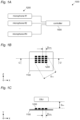
- FIG 1A schematically illustrates functional components of a watchmaking measuring device 1000 while figure 1B schematically illustrates a top view of the watchmaking measuring device 1000.
- FIG 1C a cross section of watchmaking measuring device 1000 is also schematically illustrated, which is taken along line C-C' of figure 1B .
- the watchmaking measuring device 1000 is generally for measuring sound generated by an object OBJ being a mechanical watch W.
- the object can generally be any object, preferably a small object such as a watch W, a clockwork mechanism CM of a watch W, a pen, a jewelry item, or similarly sized objects, thus generally speaking, handheld objects.
- the object OBJ is a mechanical watch W.
- the watchmaking measuring device is also called simply measuring device.
- the watchmaking measuring device comprises a supporting surface 1100.
- the supporting surface 1100 will be understood to be implementable by generally any surface, which can support a plurality of microphones.
- the supporting surface could be implemented by a plastic layer, a metallic sheet, a printed circuit board, a flexible sheet or generally any material which allows a plurality of microphones to be firmly held in place.
- the watchmaking measuring device further comprises a plurality of microphones 1200 placed on the supporting surface 1100.
- the microphones 1200 are implemented with small dimensions, preferably each microphone 1200 is smaller than 15mm 2 so that the present invention is not to be construed to be implemented by a plurality of larger, hand-held or measuring microphones such as 1 ⁇ 2" (half-inch) or 1 ⁇ 4" (quarter-inch) electret microphones or probes commonly used in the noise & vibration industry.
- the measuring device further comprises a controller 1500 connected to the plurality of microphones 1200.
- the controller can be advantageously positioned and held in place by the supporting surface 1100, although this is not mandatory.
- the controller 1500 is configured to process the output of the plurality of microphones 1200 so as to obtain a one or more signals representative of the sound generated by the object OBJ.
- the output signals of the plurality of microphones 1200 undergoes a signal processing operated by the controller 1500 so that the output of the controller 1500 is a signal which is representative of the sound generated by the object in which is a function of the signals output by the plurality of microphones 1200.
- some of the plurality of microphones 1200 might be configured to operate in a first frequency range, for instance 500 Hz to 1 kHz, while others of the plurality of microphones might be configured to operate in a second frequency range, for instance 1 kHz to 2 kHz, while further others of the plurality of microphones might be configured to operate in a third frequency range, for instance 2kHz to 4 kHz, still further others of the plurality of microphones might be configured to operate in a fourth frequency range, for instance 4 kHz to 8 kHz, still further others of the plurality of microphones might be configured to operate in a fifth frequency range, for instance 8 kHz to 16 kHz, still further others of the plurality of microphones might be configured to operate in a sixth frequency range, for instance 16 kHz to 32 kHz etc.
- the various signals output by the microphones can be combined such that the signal output by the controller is then representative of the sound generated by the object OBJ in the frequency range from 500 Hz to 32 kHz. It will be clear that this numerical example is not limiting the invention but is intended to be an example of a possible implementation in which different frequency ranges are covered by different microphones, and preferably so that the various frequency ranges are contiguous and each having twice the bandwidth of the previous one.
- At least two, preferably at least three, even more preferably at least four of the plurality of microphones 1200 might be configured to operate in the same frequency range, for instance 500 Hz to 1kHz, and their output might be combined through signal processing which takes advantage of the fact that the plurality of microphones are listening to the same sound in the same frequency range and uses their output signals to remove noise common to the output signals, and improve signal to noise ratio.
- the plurality of microphones 1200 are matched in phase and amplitude. This is particularly advantageous as it allows signal processing to combine the output of the various microphones in a reliable manner, for instance to increase bandwidth of the measured signal or to allow signal processing which increases signal-to-noise ratio.
- the combination could be also achieved without a plurality of microphones which are matched in phase and/or amplitude.
- the phase and amplitude matching can be achieved by the controller 1500. That is, the plurality of microphones 1200 and the controller 1500 can form a system which allows the plurality of microphones to be managed in phase and amplitude through signal processing and/or configuration by the controller 1500.
- the plurality of microphones can be configured to have an amplitude mismatch lower than 3 dB, preferably lower than 2 dB, even more preferably lower than 1 dB, and/or a phase mismatch lower than 10°, preferably lower than 5°, even more preferably lower than 1°.
- the inventors have found that those values enable a correct combination of the output of the plurality of microphones while also being available in commercially available systems.
- the plurality of microphones are generally small. This can be achieved, for instance, when the plurality of microphones 1200 are MEMS-based microphones.
- a MEMS-based microphone can be understood as a microphone which has a sensing element which is implemented using Micro Electronic Mechanical Systems technologies. This kind of technology is particularly advantageous as it allows the microphones to be quite small, so that a relatively high number of microphones can be placed next to each other.
- near-field measurement differs from far-field measurement in several aspects.
- a relevant one is that near-field measurement can bring a spatial scanning of a plurality of acoustic immissions and/or avoid destructive wavelength combination.
- acoustic immission as will be clear to those skilled in the art, it is meant the sound received by the microphone, as opposed to the emission being the sound emitted.
- the wavelength in air is about 34 mm so that if small microphones, with dimensions in the range of single digit millimeters, are placed close to each other they can advantageously avoid such destructive combinations. Even more preferably when considering the wavelength not in air but the wavelength of the structure-borne conduction in the structural body of the object to be measured, so a celerity of typically ten times faster than in air, the dimensions in the range of single digit millimeters and placed close to each other still even more advantageously avoid destructive combinations.
- the plurality of microphones 1200 is thus separated from each other by an intra-microphone distance D INTRA , as visible, for instance, in figure 1B and figure 1C .
- the intra-microphone distance D INTRA is preferably lower than 1/2 of a smallest wavelength to be measured by the measuring device, preferably lower than 1/4 of the smallest wavelength, even more preferably lower than 1/8 of the smallest wavelength.
- the intra-microphone distance D INTRA can be understood as being a distance between the sound-inlet openings of the microphones, such as, for instance, sound-inlet openings 1210 schematically illustrated in fig-ure 1D .
- the intra-microphone distance D INTRA is measured between any two neighboring microphones of the plurality of microphones 1200.
- the intra-microphone distance D INTRA might be measured between any two microphones of a given group of microphones of the plurality of microphones 1200 and not between any two microphones chosen at random between the plurality of microphones 1200.
- the group of microphones can be defined to comprise microphones which operate in the same frequency range.
- the group G1 can comprise microphones operating in a first frequency range
- group G2 can comprise microphone operating in a second frequency range
- group G3 can comprise microphones operating in a third frequency range
- group G4 can comprise microphones operating in a fourth frequency range.
- the plurality of microphones can be placed such that the maximum intra-microphone distance D INTRA as defined above is maintained between any two neighboring microphones, that is between any microphone and the microphone closest to it, even though two microphones chosen at random in the plurality of microphones may be placed at a distance higher than the maximum intra-microphone distance D INTRA . Also in this case, at least the two neighboring microphones can be ensured to operate without destructive wavelength interference.
- the plurality of microphones 1200 together cover a total distance D TOT , the total distance D TOT being lower than a smallest wavelength to be measured by the measuring device, preferably lower than 1/2 of the smallest wavelength.
- the total distance D TOT can be lower than 10cm, preferably lower than 5cm, even more preferably lower than lower than 3cm.
- the total distance D TOT can be defined as the largest distance covered by the plurality of microphones 1200.
- the measuring device is more compact. Moreover, it can be ensured that the sound generated by the object reaches all microphones with a comparable amplitude. Furthermore, concentrating the microphones in a smaller region makes it simpler to measure a local source effect in the object and to isolate this smaller region from environmental noise.
- the plurality of microphones 1200 comprises at least 4 microphones, preferably at least 16 microphones, even more preferably at least 32 microphones.
- the plurality of microphones 1200 can be configured to implement an acoustic antenna.
- an acoustic antenna can be understood as a device comprising an array of microphones that is used to detect sound waves from a particular direction.
- An acoustic antenna typically consists of a plurality of microphones arranged in a predetermined pattern. The signals from these microphones, combined with the knowledge of the positions of the microphones, can be processed to determine from which direction a sound wave is originated.
- the predetermined pattern of the microphones can be various and the positioning of the microphones 1200 is not limited to the one illustrated in figure 1B , where they are placed in a substantially array configuration.
- the microphones 1200 can be placed with a circular pattern or, for instance as illustrated in figure 3B , the microphones 1200 can be placed as groups G1-G4.
- the plurality of microphones can be placed with various nonuniform patterns.
- the bandwidth of the sound generated by the object can be divided in a plurality of smaller bandwidths and each of the smaller bandwidth can be measured by one or more of the plurality of microphones 1200.
- the plurality of microphones 1200 can therefore comprise at least 2, preferably at least 4, microphones 1200 and/or or at least 2, preferably at least 4, groups G1-G4 of microphones, each group comprising one or more microphones. Different microphones, or different groups of microphones, can then be configured to measure sounds on different frequency ranges.
- the output of the microphones, or groups can be combined to increase the bandwidth which is measured.
- the present invention is generally not limited in how the larger bandwidth is subdivided in a plurality of smaller frequency ranges.
- the number and the size of these smaller frequency ranges can be selected depending on the specific implementation and on the characteristics of the microphones 1200.
- At least two of the different frequency ranges can be configured to be contiguous. That is, for instance, one frequency range can extend from a first value to a second value and another frequency range can extend from the second value to a third value.
- a majority of the different frequency ranges can be configured to be contiguous. In this manner, it can be advantageously ensured that no gaps are present in the measurement while also ensuring that the same frequency is not sampled more than once which might result in unnecessary redundancy.
- the different frequency ranges can be configured to each be twice as large as the smaller contiguous frequency range.
- the frequency ranges have respective bandwidths, and for frequency ranges which are contiguous, the bandwidth or the higher frequency range is double the bandwidth or the lower frequency range. For instance, if a first frequency range has a bandwidth of 5 kHz, for instance from 5 kHz to 10 kHz, the subsequent higher frequency range can have a bandwidth of 10 kHz, for instance from 10 kHz to 20 kHz, and the further subsequent frequency range can have a bandwidth of 20 kHz, for instance from 20 kHz to 40 kHz.
- the different frequency ranges can each be defined by a respective minimum frequency value and maximum frequency value, and a ratio of the maximum frequency value over the minimum frequency can be at least 1.1, preferably at least 1.2, even more preferably at least 1.5, and/or the ratio of the maximum frequency value over the minimum frequency can be at most 4, preferably at most 3, even more preferably at most 2.
- the different frequency ranges can be preferably higher than 5 kHz, preferably higher than 2 kHz, even more preferably higher than 500 Hz, and/or lower than 80 kHz, preferably between lower than 120 kHz, even more preferably lower than 200 kHz.
- the sounds can be measured over a certain bandwidth while one or more of the microphones can operate in a frequency range which is more than said bandwidth.
- a microphone can measure in the bandwidth 500 Hz to 200 kHz, it might be used for measuring sounds in a narrower bandwidth only, such as 500 Hz to 1 kHz. It will be clear to those skilled in the arts that this can be implemented in a plurality of manner.
- a microphone configured to operate in a given frequency range can be selected to have measuring characteristics adapted to that frequency range. For instance, assuming as an example that the complete measuring bandwidth is 5 kHz to 80 kHz, and assuming as an example that this is divided into two ranges, for instance 5 kHz to 40 kHz and 40 kHz to 80 kHz, a microphone which is better suited at measuring in the range of 5 kHz to 40 kHz can be used for this range while a different microphone, which is better suited as measuring in the range from 40 kHz to 80 kHz, can be used in this range. That is, different microphones can be used for different frequency ranges.
- a plurality of, preferably a majority of, the plurality of microphones 1200 can be capable of measuring sound in the same bandwidth, and the different frequency ranges can be defined by respective different bandpass filters, which are configured to act on the output of the microphones 1200.
- both microphones can be capable of measuring from 5 kHz to 80 kHz and both microphones can be configured to do so, while their output can then be filtered differently.
- the output of one or more of the microphones can be filtered by a bandpass filter configured to allow frequencies between 5 kHz and 40 kHz and the output of one or more of the remaining microphones can be filtered by a bandpass filter configured to allow frequencies between 40 kHz and 80 kHz.
- This implementation has been found to be particularly advantageous as it allows using the same microphones, which in turn simplifies manufacturing and design, while the different filters simplify the definition of the frequency ranges, since filters can be more freely configured than the microphones.
- one of the advantages achieved by the invention is the improvement of the signal-to-noise ratio by measuring coherent signals through a plurality of microphones 1200.
- the controller 1500 can then be configured to apply any such algorithm and in particular any signal processing to output signals of the plurality of microphones 1200 so as to reduce noise common to the output signals.
- the combination of the microphones allows signal processing which makes their combination to have a lower noise rating, and/or a higher sensitivity, than a single microphone. While the various algorithms to reduce noise might be - per se - known, the members have found that their application to the specific measuring device of the invention is not known from the prior art.
- each of the plurality of microphones 1200 can have a self-noise level which is higher than a minimum sound to be measured from the object OBJ.
- the combined noise level might be lower than the minimum sound to be measured so as to allow the correct detection of sounds from the object.
- microphones which are commercially available and which, at the single microphone level, might not have characteristics which are insufficient for measuring objects emitting noise with very low amplitudes, such as the level of noises emitted by a mechanical watch.
- such microphones can be cheaper than more specialized microphones and, when combined together, the combination can still be cheaper than the more specialized microphone while nevertheless obtaining a broader band and an increased signal to noise ratio.
- the supporting surface 1100 has been generally described as a mechanical element which allows the plurality of microphones 1200 be supported on it and, preferably, be firmly held in place.
- the supporting surface 1100 comprises, or is, a printed circuit board, to which the plurality of microphones 1200 are electrically connected.
- the plurality of microphones 1200 has only been disclosed as generally being assembled on supporting surface 1100, without specific indication on the characteristics of the microphones and their orientation.
- the plurality of microphones 1200 can be placed on a side of the supporting surface 1100 facing the object OBJ. This is particularly advantageous since it allows the object to be placed in near proximity to the plurality of microphones.
- the supporting surface 1100 can have a plurality of openings 1110.
- the plurality of microphones 1200 can be configured as illustrated in the enlarged portion of figure 1D , namely by a microphone 1200D, wherein, each of the plurality of microphones 1200D can comprise a sound-inlet opening 1210.
- the microphones 1200D can be implemented instead of the microphones 1200 in any of the embodiments disclosed in the application.
- the sound-inlet opening can be understood as an opening in the housing of the microphone 1200D through which the majority of sound intended to reach the sensing part of the microphone 1200D can travel.
- the plurality of microphones 1200D can be assembled on the supporting surface 1100 so that the plurality of microphones 1200D closes the plurality of openings 1110, and so that the plurality of sound-inlet openings 1210 faces the plurality of openings 1110.
- a microphone 1200D can close an opening 1110, as well as sound-inlet opening 1210 on the side of the opening 1110. In this manner, sound from the object can travel and through the sound-inlet opening 1210 and reach the sensing part of the microphone 1200D.
- This particularly advantageous combination allows the object OBJ to be positioned very close to, or even on top of, supporting surface 1110. In this manner, the object OBJ can be placed very close to the microphones 1200D. Moreover, particularly in those cases in which the object is supported by the supporting surface 1110, the object OBJ can close the openings 1100 on the side opposite to the microphones 1200D so that the amount of environmental noise reaching the sensing portion of microphones 1200D can be drastically reduced and the sound captured from the object OBJ can be very local.
- the microphones 1200D are not to be used only in the presence of openings 1110 in the supporting surface 1100, as it is illustrated for instance in figure 1D .
- the various embodiments described as so far allow the object to be positioned in close proximity, or even in direct contact, with the microphones 1200. This allows the invention to operate a near-field measurement.
- the measuring device can be configured so that, in use, a measuring distance D DEV between any of the plurality of microphones 1200, 1200D and the object OBJ, is less than 2 cm, preferably less than 1 cm, even more preferably less than 5mm.
- the measuring device can be configured so that the object OBJ is held at said measuring distance D DEV without additional support. It will be clear to those skilled in the art, this can be achieved by providing an appropriate frame for holding the object OBJ.
- the supporting surface 1100 can be configured so as to hold the object in place.
- the part of the measuring device holding the object in place can be shaped to have a shape complementary to at least part of the external shape of the object, such that the object OBJ can be held firmly and securely, as well as reducing the amount of environmental noise which reaches the microphone thanks to the complementarity of the supporting structure and the shape of the object OBJ.
- the microphones are supported by supporting surface 1100, which has a generally planar configuration. It will be clear to those skilled in the art that this is not necessarily the only shape that the supporting surface 1100. In particular, supporting surface 1100 can be bend, to form a non-planar housing and/or can be a part of a housing. Examples of this configuration will be described with reference to figures 2A to 2H .
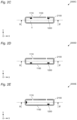
- Figure 2A schematically illustrates a cross section of a measuring device 2000, taken along line A-A' of figure 2B
- Figure 2B schematically illustrates a bottom view of a measuring device 2000, cut open along line B-B' of figure 2A so as to show a possible the positioning of the microphones 1200.
- the measuring device 2000 can further comprise a housing 2100 configured to define a volume V.
- the volume V is thus an internal volume of the housing 2100.
- the housing 2100 can comprise, or can be connected to, the supporting surface 1100, so that the plurality of microphones 1200 can be placed inside of the volume V.
- the supporting surface 1100 can comprises at least one opening 1110.
- the housing 2100 can be configured to support the object OBJ so that the object OBJ, during measurement, overlaps with the at least one opening 1110.
- the object OBJ can be positioned on the housing 2100 so as to close at least one of, preferably a majority of, even more preferably all of, the openings 1110. This further reduces the amount of environmental noise reaching the microphones 1200. Even more preferably, the volume V is open to the exterior only through openings 1110 such that, when those are closed by the object, the amount of environmental noise reaching the volume V can be significantly reduced.
- the microphones 1200 are placed on the supporting surface 1100 which is implemented on the top of the housing 2100
- the present invention is not limited thereto.
- This implementation is particularly advantageous in that it places the microphones 1200 as close as possible to the object OBJ.
- alternative implementations are possible in which the microphones 1200 are placed at other locations of the housing 2100.
- the housing can have a top surface and a bottom surface and the microphones 1200 could be placed on the bottom surface of the housing 2100, thus acting as supporting surface 1100.
- the microphones 1200 could be placed on vertical surfaces of the housing 2100.
- not all microphones 1200 need to be placed on the same surface of the housing 2100.
- the microphones 1200 are placed in close proximity of the openings 1110. In some embodiments, the distance between an opening 1110 and the closest respective microphone 1200 is less than 1 cm, preferably less than 3 mm, even more preferably less than 1 mm. While in the embodiment of figure 2A and 2B the microphones 1200 are placed between the openings 1100 and then, it will be clear to those skilled in the art that the alternative implementation is also possible, such as illustrated in figure 2C .
- each of the plurality of openings 1110 can have an area comprised between 0.5mm 2 and 50mm 2 , preferably between 0.5mm 2 and 25mm 2 , even more preferably between 0.5mm 2 and 5mm 2 .
- the inventors have in particularly found that those numerical values allow the transmission of a sufficient amount of sound from the object OBJ to be measured, while also effectively shielding the microphones from environmental noise.
- a seal can be used to limit the amount of environmental noise reaching the microphones 1200.
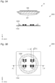
- An example thereof is illustrated in the embodiments of figures 3A and 3B .
- measuring device 3000 can further comprise a noise-reducing seal 3300.
- the noise-reducing seal 3300 is configured to limit environmental noise from reaching the plurality of microphones 1200.
- the noise-reducing seal 3300 can be implemented with any material that has the capability of limiting sound transmission through it. As an example, foam or rubber could be used. Alternatively, or in addition, a soft surface coating can be used as noise-reducing seal. In general, a material which reduces the amount of environmental noise from reaching the plurality of microphones can be used as noise-reducing seal 3300.
- the noise-reducing seal 3300 can encircle an area of at least 50%, and/or and at most 100%, of the frontal area of the watch W. In alternative embodiments, the noise-reducing seal 3300 can encircle an area preferably higher than 4 cm 2 , even more preferably higher than between 10 cm 2 , and/or preferably smaller that 20cm 2 , even more preferably smaller than 16cm 2 .
- the noise-reducing seal 3300 can be flexible, and in particular to a degree which allows the noise-reducing seal 3300 to be compressed under the weight of the object.
- the ratio of the thickness of the noise reducing seal 3300 when compressed by the object OBJ over the thickness of the noise reducing seal 3300 when non compressed by the object OBJ can be in a range of 95/100 to 80/100.
- the noise-reducing seal 3300 can have a shape complementary to at least part of a shape of the object OBJ.
- the illustrated embodiment shows a mechanical watch W as object to be measured, having a front WF and a back WB.
- the seal 3300 has a shape complementary to a part of the front WF of the watch W, such that when the watch W is placed on the noise-reducing seal 3300 a volume V1 comprised between the object OBJ, in this case the watch W and the supporting surface W becomes closed by the noise-reducing seal 3300.
- the same approach can be implemented also when the microphones 1200D are placed on the opposite side of the supporting surface 1100, in which case the volume closed by the noise-reducing seal 3300 also comprises the openings 1110.
- the noise-reducing seal 3300 can be configured to encircle all openings, as visible in figure 3C , or as little as one opening 1110 can be encircled by a respective noise-reducing seal 3300, as visible in figure 3D .
- Any intermediate configuration, in which one or more openings, preferably all openings, are encircled by noise-reducing seal 3300 or soft material are also possible.
- the supporting surface 1110 has been described as being substantially stiff.
- the present invention is however not limited thereto.
- the supporting surface 4100 can be flexible and configured to conform to a surface of the object OBJ, in the illustrated embodiment being a watch W.
- FIG. 4 While the embodiment of figure 4 is illustrated in conjunction with microphones 1200D measuring through openings 1110, it will be clear that a similar approach can be implemented with the microphones placed on the side of supporting surface 4100 facing the object OBJ.
- the flexible supporting surface 4100 can be held in place by an appropriate non-flexible supporting frame 4400, which is only schematically illustrated in figure 4 .
- the supporting frame 4400 can be configured so that the flexible supporting surface 4100 can move under the weight of the object OBJ such that the flexible supporting surface 4400 can be bent to conform to the shape of the object OBJ, at least to the part of object OBJ in touch with the flexible supporting surface 4100.
- the supporting surface 4100 can be coated with a soft material or receive a piece of soft material, such as felt, to act as a surface seal around the openings and/or to provide a soft material for smooth contact with the watch to measure and improve acoustic measurement by limiting sound leaks.
- the watchmaking measuring device 4000 has a plurality of microphones 1200D, preferably MEMS based microphones, supported on an internal side of the flexible supporting surface 4100.
- the flexible supporting surface 4100 conforms to the surface of the mechanical watch (e.g. the bottom or the glass) on its external side.
- the flexible supporting surface 4100 has one or more openings 1110 which are closed by the installed watch and the microphone on the other side.
- the flexible supporting surface 4100 has preferably a flexible PCB to support and connect the microphones.
- the MEMS-based microphones each have preferably a diaphragm to transform the acoustic signal (via e.g. air) to a corresponding electric signal.
- Each of the MEMS-based microphones has a MEMS opening facing the opening 1110 of the flexible supporting surface 4100 to allow air (or fluid or gel) to vibrate between a diaphragm of the MEMS and the watch. This is an acoustic near field measurement.
- a volume comprised between at least the object OBJ and a majority, preferably all, of the plurality of microphones 1200 can be filled by a liquid and/or by a gel. Even more preferably, in use, the device and the object can be within a liquid and/or a gel. It will be clear to those skilled in the art that, in those applications, the microphones can be configured to operate in a liquid and/or a gel.
- a volume V1 can be defined between the microphones and the object.
- this volume comprises the openings 1110 and any sound-inlet volume of the microphones 1200D.
- this volume comprises the sound-inlet volume of the microphones 1200D.
- the volume further comprises the volume defined by the supporting surface 1100, the seal 3300 and the object OBJ. It will thus be clear that the volume is variable in size and definition, but it generally can be understood as a closed volume which is surrounded by at least part of the object OBJ and the sound-inlet opening 1210.
- the measuring device is configured so that, in use, this volume, namely a volume between any of the plurality of microphones 1200, 1200D and the object OBJ is less than 2 cm 3 , preferably less than 1 cm 3 , even more preferably less than 10 mm 3 .
- liquid and/or gel is used as fluid, at least this volume can be filled by the liquid and/or gel.
- the invention finds a particularly advantageous application when the object OBJ is a mechanical watch W, or a clockwork mechanism CM of a mechanical watch W.
- an embodiment of the invention can relate to a method for measuring sound generated by an object OBJ, wherein the method comprises arranging a plurality of microphones 1200 on a supporting surface 1100 of a measuring device. It will be clear that the measuring device can be any of the devices described above.
- the method further comprises providing a controller 1500 connected to the plurality of microphones 1200, and configuring the controller 1500 to combine the output of the plurality of microphones 1200, in any of the manners previously described.
- the method further comprises measuring sounds generated by the object OBJ by means of the plurality of microphones 1200 in any of the manners previously described.
- the method can further comprise filling with a liquid and/or a gel at least a volume V1 comprised between the object OBJ and any one of a majority, preferably all, of the plurality of microphones 1200. That is, in presence of a plurality of microphones, the volume between any of the microphones and the object, as described above, can be filled with a liquid and/or a gel.
- the method can further comprise positioning the object OBJ at a measuring distance D DEV from the plurality of microphones 1200, as previously described, which is less than 1 cm, preferably less than 0,5 cm, even more preferably less than 1 mm.
- the plurality of microphones can be physically separated into several clusters and at least two clusters can be placed on two different sides of the object to be measured. It will be clear that this can be achieved by providing a supporting surface which is shaped accordingly or by providing more than one supporting surfaces and dividing the microphones between those. All features described above with reference to a single supporting surface can then be applied to any of those supporting surfaces.
- a first cluster of the plurality microphones can be positioned on a bottom face of the object OBJ and a second cluster can be positioned on a top face of the object. Also in this configuration, the plurality of microphones can still be all connected to the same controller.
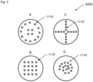
- Figure 5 schematically illustrates a top view of the watchmaking measuring device 4000.
- Figure 5 illustrates possible shape of openings 1110.
- the view A shows the openings 1110 arranged in a circular shape on the outside periphery of the measuring device with also four openings 1110 arranged in a square shape at the center of the measuring device 4000.
- the view B shows the openings 1110 arranged in a square shape on the measuring device 4000.
- the view C shows the openings 1110 arranged in a cross shape on the measuring device 4000.
- the view D shows the openings 1110 arranged in a spiral shape on the measuring device 4000.
- the openings 1110 are preferably covered with the microphones 1200D.
- a preferred example of the measuring device (sound recording system) according to the invention is a multi-microphone contact head such as comprising 4, 8, 16 or 32 ultrasonic MEMS microphones.
- each microphone consists of an orifice 1 mm in diameter and 0.4 mm deep. There is a direct contact between the mouth of the ports and the wall of the watch being palpated, through 0.2mm thick elastomer or felt.
- the orifices are placed on a circular plate with an external diameter of 25 mm.
- the distribution of the ports being, for example (in the case of 16 microphones):
- the direct contact of the individual acoustic access ports of the microphones with the room to be tested provides, by definition, a maximum gain in signal-to-noise ratio compared with any other method of acoustic pick-up at a greater distance (laws of geometric attenuation and dissipation of sound waves in the air).
- the distribution of the acoustic accesses of the array of independent microphones thus formed makes it possible to pick up acoustic signals comprising both coherent and non-coherent components.
- the non-coherent components of the signal of interest provide additional information about the acoustic behaviour of the room under test.
- the non-coherent background noise components are added together in a non-constructive way: the overall background noise level of the measurement is then set at -10LOG(n) of the level of the background noise of a microphone taken in isolation, where n is the number of microphones.
- the coherent signal components of interest add up constructively, giving a theoretical gain of +10LOG(n) over the sensitivity of a single microphone, where n is the number of microphones.
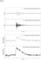
- Figure 6 shows performance comparison between the prior art and the present invention about waveform during time passing.
- the first graph represents a waveform of the signal captured by a single-point resonant sensing head according to the prior art.
- the second graph represents a waveform of the signal captured by a multi-point non-resonant sensing head according to the present invention.
- the third graph represents an envelope of the signal captured by the single-point resonant sensing head according to the prior art
- the fourth graph represents an envelope of the signal captured by the multi-point non-resonant sensing head according to the present invention.
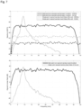
- Figure 7 shows performance comparison between the prior art and the present invention about spectrum and signal to noise ration with respect to frequency.
- the first graph shows spectrum according to the prior art and according to the present invention.
- the second graph shows SNR according to the prior art and according to the present invention.
- the present invention allows for a better detection, better sensibility on a larger band width.
- Graphs on figures 6-7 are illustrative of a prior art resonant sensing head e.g. single-point palpation with a resonant sensor in the 500 - 20 kHz band, being a sensor resonant at around 9 kHz, high sensitivity, low noise.
- Graphs on figures 6-7 are illustrative of the present invention with a wideband multipoint near-field stethoscope at 500 Hz - 200 kHz, with four microphones at 0.4mm from the watch and frequency band between 3 kHz and 45 kHz.
- an automatic detection of the shock instant of the watch mechanism is performed, based on a rectified envelope with very high temporal resolution (integration time 100 microseconds).
- the emergence (prominence) of the signal is much higher; the rise time is shorter (i.e. the slope is steeper (sharpness)).
- the shock time stamp is more accurate.
- Figure 8 shows performance comparison between the prior art and the present invention about waveform envelop of a single transient signal during time passing.
- Figure 9 shows performance comparison between the prior art and the present invention about spectrum of the single transient signal with respect to frequency.
- Figure 10 shows performance comparison between the prior art and the present invention about SNR.
- Figure 11 shows performance comparison between the prior art and the present invention about SNR and global gain.
Landscapes
- Physics & Mathematics (AREA)
- General Physics & Mathematics (AREA)
- Health & Medical Sciences (AREA)
- General Health & Medical Sciences (AREA)
- Acoustics & Sound (AREA)
- Life Sciences & Earth Sciences (AREA)
- Chemical & Material Sciences (AREA)
- Analytical Chemistry (AREA)
- Biochemistry (AREA)
- Immunology (AREA)
- Pathology (AREA)
- Engineering & Computer Science (AREA)
- Otolaryngology (AREA)
- Signal Processing (AREA)
- Measurement Of Mechanical Vibrations Or Ultrasonic Waves (AREA)
Applications Claiming Priority (1)
| Application Number | Priority Date | Filing Date | Title |
|---|---|---|---|
| EP23170985.8A EP4459248A1 (de) | 2023-05-02 | 2023-05-02 | Nahfeld-objektmessvorrichtung auf schallbasis und verfahren |
Publications (1)
| Publication Number | Publication Date |
|---|---|
| EP4459249A1 true EP4459249A1 (de) | 2024-11-06 |
Family
ID=86328316
Family Applications (2)
| Application Number | Title | Priority Date | Filing Date |
|---|---|---|---|
| EP23170985.8A Withdrawn EP4459248A1 (de) | 2023-05-02 | 2023-05-02 | Nahfeld-objektmessvorrichtung auf schallbasis und verfahren |
| EP24170087.1A Pending EP4459249A1 (de) | 2023-05-02 | 2024-04-12 | Nahfeldmessvorrichtung und -verfahren für schallbasierte uhrenherstellung |
Family Applications Before (1)
| Application Number | Title | Priority Date | Filing Date |
|---|---|---|---|
| EP23170985.8A Withdrawn EP4459248A1 (de) | 2023-05-02 | 2023-05-02 | Nahfeld-objektmessvorrichtung auf schallbasis und verfahren |
Country Status (1)
| Country | Link |
|---|---|
| EP (2) | EP4459248A1 (de) |
Citations (6)
| Publication number | Priority date | Publication date | Assignee | Title |
|---|---|---|---|---|
| WO2009131807A2 (en) * | 2008-04-20 | 2009-10-29 | Stalix Llc | Acoustic and ultrasonic concealed object detection |
| FR3033654A1 (fr) * | 2015-03-11 | 2016-09-16 | Lepsi Sarl | Porte mouvement d'une piece d'horlogerie |
| WO2019231632A1 (en) * | 2018-06-01 | 2019-12-05 | Shure Acquisition Holdings, Inc. | Pattern-forming microphone array |
| US10806431B2 (en) * | 2013-09-25 | 2020-10-20 | Massachusetts Institute Of Technology | Application specific integrated circuit with column-row-parallel architecture for ultrasonic imaging |
| EP3779496A1 (de) * | 2018-03-30 | 2021-02-17 | Vecsense Technology Co., Ltd | Kleine vorrichtung und verfahren zur azimutdetektion einer räumlichen schallquelle |
| CH717688A1 (fr) * | 2020-07-27 | 2022-01-31 | Metallo Tests Sa | Système, dispositif et méthode de contrôle du fonctionnement d'un ensemble fonctionnel d'une pièce d'horlogerie. |
-
2023
- 2023-05-02 EP EP23170985.8A patent/EP4459248A1/de not_active Withdrawn
-
2024
- 2024-04-12 EP EP24170087.1A patent/EP4459249A1/de active Pending
Patent Citations (6)
| Publication number | Priority date | Publication date | Assignee | Title |
|---|---|---|---|---|
| WO2009131807A2 (en) * | 2008-04-20 | 2009-10-29 | Stalix Llc | Acoustic and ultrasonic concealed object detection |
| US10806431B2 (en) * | 2013-09-25 | 2020-10-20 | Massachusetts Institute Of Technology | Application specific integrated circuit with column-row-parallel architecture for ultrasonic imaging |
| FR3033654A1 (fr) * | 2015-03-11 | 2016-09-16 | Lepsi Sarl | Porte mouvement d'une piece d'horlogerie |
| EP3779496A1 (de) * | 2018-03-30 | 2021-02-17 | Vecsense Technology Co., Ltd | Kleine vorrichtung und verfahren zur azimutdetektion einer räumlichen schallquelle |
| WO2019231632A1 (en) * | 2018-06-01 | 2019-12-05 | Shure Acquisition Holdings, Inc. | Pattern-forming microphone array |
| CH717688A1 (fr) * | 2020-07-27 | 2022-01-31 | Metallo Tests Sa | Système, dispositif et méthode de contrôle du fonctionnement d'un ensemble fonctionnel d'une pièce d'horlogerie. |
Also Published As
| Publication number | Publication date |
|---|---|
| EP4459248A1 (de) | 2024-11-06 |
Similar Documents
| Publication | Publication Date | Title |
|---|---|---|
| US7460439B2 (en) | Ultrasonic transducer for ranging measurement with high directionality using parametric transmitting array in air and a method for manufacturing same | |
| US5996415A (en) | Apparatus and method for characterizing semiconductor wafers during processing | |
| Manthey et al. | Ultrasonic transducers and transducer arrays for applications in air | |
| US5191796A (en) | Acoustic-emission sensor | |
| Gachagan et al. | Characterization of air-coupled transducers | |
| US5029474A (en) | Transducer and method for acoustic emission (AE) testing | |
| EP2956840B1 (de) | Berührungslose benutzeroberflächen | |
| US20180115855A1 (en) | Method and system for acoustic source enhancement using acoustic sensor array | |
| US20120294119A1 (en) | Device for detecting acoustic waves and a system for locating a source of acoustic waves | |
| Kang et al. | Directional sound sensor with consistent directivity and sensitivity in the audible range | |
| JPH0643044A (ja) | 複合した力、ひずみ及び音響の発生変換器 | |
| Zhang et al. | Multi-band asymmetric piezoelectric MEMS microphone inspired by the Ormia ochracea | |
| KR100935058B1 (ko) | 수음 장치 | |
| EP4459249A1 (de) | Nahfeldmessvorrichtung und -verfahren für schallbasierte uhrenherstellung | |
| KR20210146811A (ko) | 마이크로폰을 테스트하기 위한 테스트 장치 | |
| Zhang et al. | A MEMS microphone inspired by Ormia for spatial sound detection | |
| Liu et al. | Multi-band MEMS resonant microphone array for continuous lung-sound monitoring and classification | |
| CN116086593A (zh) | 一种基于n个谐响应mems敏感单元集成的声压振速fft传感器及其工作方法 | |
| US20120294121A1 (en) | Transducer for Phased Array Acoustic Systems | |
| JP4468280B2 (ja) | マイクロホン装置 | |
| JP2009071395A (ja) | 超音波受信素子及びこれを用いた超音波トランスデューサ | |
| Ramesh et al. | Lumped-parameter modeling and performance analysis of fluid-backed piezoceramic flexural disc acoustic sensors | |
| US20220326188A1 (en) | Multi frequency acoustic emission micromachined transducers for non-destructive evaluation of structural health | |
| KR101434328B1 (ko) | 다중 파장 공진형 초음파 센서 어레이 | |
| RU216445U1 (ru) | Чувствительный элемент приемников градиента акустического давления |
Legal Events
| Date | Code | Title | Description |
|---|---|---|---|
| PUAI | Public reference made under article 153(3) epc to a published international application that has entered the european phase |
Free format text: ORIGINAL CODE: 0009012 |
|
| STAA | Information on the status of an ep patent application or granted ep patent |
Free format text: STATUS: THE APPLICATION HAS BEEN PUBLISHED |
|
| AK | Designated contracting states |
Kind code of ref document: A1 Designated state(s): AL AT BE BG CH CY CZ DE DK EE ES FI FR GB GR HR HU IE IS IT LI LT LU LV MC ME MK MT NL NO PL PT RO RS SE SI SK SM TR |
|
| STAA | Information on the status of an ep patent application or granted ep patent |
Free format text: STATUS: REQUEST FOR EXAMINATION WAS MADE |
|
| 17P | Request for examination filed |
Effective date: 20250429 |