EP4459208A2 - Luftgekühlter kühlschrank - Google Patents
Luftgekühlter kühlschrank Download PDFInfo
- Publication number
- EP4459208A2 EP4459208A2 EP24201405.8A EP24201405A EP4459208A2 EP 4459208 A2 EP4459208 A2 EP 4459208A2 EP 24201405 A EP24201405 A EP 24201405A EP 4459208 A2 EP4459208 A2 EP 4459208A2
- Authority
- EP
- European Patent Office
- Prior art keywords
- water receiving
- evaporator
- air
- plate segment
- water
- Prior art date
- Legal status (The legal status is an assumption and is not a legal conclusion. Google has not performed a legal analysis and makes no representation as to the accuracy of the status listed.)
- Pending
Links
Images

Classifications
-
- F—MECHANICAL ENGINEERING; LIGHTING; HEATING; WEAPONS; BLASTING
- F25—REFRIGERATION OR COOLING; COMBINED HEATING AND REFRIGERATION SYSTEMS; HEAT PUMP SYSTEMS; MANUFACTURE OR STORAGE OF ICE; LIQUEFACTION SOLIDIFICATION OF GASES
- F25D—REFRIGERATORS; COLD ROOMS; ICE-BOXES; COOLING OR FREEZING APPARATUS NOT OTHERWISE PROVIDED FOR
- F25D11/00—Self-contained movable devices, e.g. domestic refrigerators
- F25D11/02—Self-contained movable devices, e.g. domestic refrigerators with cooling compartments at different temperatures
-
- F—MECHANICAL ENGINEERING; LIGHTING; HEATING; WEAPONS; BLASTING
- F25—REFRIGERATION OR COOLING; COMBINED HEATING AND REFRIGERATION SYSTEMS; HEAT PUMP SYSTEMS; MANUFACTURE OR STORAGE OF ICE; LIQUEFACTION SOLIDIFICATION OF GASES
- F25D—REFRIGERATORS; COLD ROOMS; ICE-BOXES; COOLING OR FREEZING APPARATUS NOT OTHERWISE PROVIDED FOR
- F25D21/00—Defrosting; Preventing frosting; Removing condensed or defrost water
- F25D21/06—Removing frost
- F25D21/08—Removing frost by electric heating
-
- F—MECHANICAL ENGINEERING; LIGHTING; HEATING; WEAPONS; BLASTING
- F25—REFRIGERATION OR COOLING; COMBINED HEATING AND REFRIGERATION SYSTEMS; HEAT PUMP SYSTEMS; MANUFACTURE OR STORAGE OF ICE; LIQUEFACTION SOLIDIFICATION OF GASES
- F25D—REFRIGERATORS; COLD ROOMS; ICE-BOXES; COOLING OR FREEZING APPARATUS NOT OTHERWISE PROVIDED FOR
- F25D21/00—Defrosting; Preventing frosting; Removing condensed or defrost water
- F25D21/14—Collecting or removing condensed and defrost water; Drip trays
-
- F—MECHANICAL ENGINEERING; LIGHTING; HEATING; WEAPONS; BLASTING
- F25—REFRIGERATION OR COOLING; COMBINED HEATING AND REFRIGERATION SYSTEMS; HEAT PUMP SYSTEMS; MANUFACTURE OR STORAGE OF ICE; LIQUEFACTION SOLIDIFICATION OF GASES
- F25D—REFRIGERATORS; COLD ROOMS; ICE-BOXES; COOLING OR FREEZING APPARATUS NOT OTHERWISE PROVIDED FOR
- F25D23/00—General constructional features
- F25D23/006—General constructional features for mounting refrigerating machinery components
-
- F—MECHANICAL ENGINEERING; LIGHTING; HEATING; WEAPONS; BLASTING
- F25—REFRIGERATION OR COOLING; COMBINED HEATING AND REFRIGERATION SYSTEMS; HEAT PUMP SYSTEMS; MANUFACTURE OR STORAGE OF ICE; LIQUEFACTION SOLIDIFICATION OF GASES
- F25D—REFRIGERATORS; COLD ROOMS; ICE-BOXES; COOLING OR FREEZING APPARATUS NOT OTHERWISE PROVIDED FOR
- F25D23/00—General constructional features
- F25D23/06—Walls
- F25D23/065—Details
- F25D23/066—Liners
-
- F—MECHANICAL ENGINEERING; LIGHTING; HEATING; WEAPONS; BLASTING
- F25—REFRIGERATION OR COOLING; COMBINED HEATING AND REFRIGERATION SYSTEMS; HEAT PUMP SYSTEMS; MANUFACTURE OR STORAGE OF ICE; LIQUEFACTION SOLIDIFICATION OF GASES
- F25D—REFRIGERATORS; COLD ROOMS; ICE-BOXES; COOLING OR FREEZING APPARATUS NOT OTHERWISE PROVIDED FOR
- F25D2321/00—Details or arrangements for defrosting; Preventing frosting; Removing condensed or defrost water, not provided for in other groups of this subclass
- F25D2321/14—Collecting condense or defrost water; Removing condense or defrost water
- F25D2321/144—Collecting condense or defrost water; Removing condense or defrost water characterised by the construction of drip water collection pans
- F25D2321/1441—Collecting condense or defrost water; Removing condense or defrost water characterised by the construction of drip water collection pans inside a refrigerator
Definitions
- the present invention relates to refrigerating and freezing technologies, and particularly relates to an air-cooled refrigerator.
- a cooling chamber is located on the lower portion of the refrigerator, the evaporator is internally provided at the bottom of the cooling chamber, and in order to increase the volume rate and safety of the technology of providing the evaporator at the bottom, a heating wire, e.g., an aluminum tube heating wire, is generally adopted as a defrosting device of the evaporator.
- a heating wire e.g., an aluminum tube heating wire
- the temperature of the aluminum tube heating wire will not be set too high, and it may lead to a situation that a fault occurs if large ice blocks a water drainage outlet and cannot be melted in time.
- One objective of the present invention is to overcome at least one defect in the prior art and to provide an air-cooled refrigerator.
- One further objective of the present invention is to prevent a water drainage outlet of a cooling chamber of the refrigerator from being blocked.
- Another further objective of the present invention is that as for the air-cooled refrigerator where the cooling chamber is located at the bottom and an evaporator is obliquely provided in the cooling chamber, defrosting water on the evaporator is collected by a water receiving tray to the greatest extent.
- Yet another further objective of the present invention is to optimize the shape of a heating wire to make the evaporator heated more evenly.
- the present invention provides an air-cooled refrigerator, including:
- bottom wall of the bottom liner includes:
- an inclination angle of the third oblique portion is greater than that of the second oblique portion.
- the water receiving tray includes:
- a distance between the front plate segment and the first oblique portion is configured as any numerical value within a range from 20 mm to 45 mm.
- the heating wire includes:
- the heating wire also includes: an expansion section, a middle portion of the expansion section being provided abutting against the front plate segment and the expansion section extending towards two sides to a position close to a side wall of the bottom liner to conduct defrosting heating on a region in front of the evaporator.
- a plurality of limiting parts are provided on positions of a rear portion of an upper surface of the middle plate segment facing towards the plurality of connection sections to limit the connection sections.
- a plurality of water drainage holes are also formed in a front portion of the upper surface of the middle plate segment to discharge water received by the water receiving tray into the water receiving tank through the water drainage holes and gaps between the through holes and the extension portion.
- a distance between a bottom end of the extension portion and the water drainage outlet is configured as any numerical value within a range from 3 mm to 5 mm.
- the water receiving tray is provided between the evaporator and the bottom wall of the bottom liner.
- the heating wire is provided between the water receiving tray and the evaporator in the coiled manner.
- the plurality of through holes are formed in the region of the water receiving tray facing towards the water receiving tank.
- the heating wire has the extension portion extending to the water receiving tank through the through holes. After the extension portion penetrates through the through holes, at least part of the extension portion is provided in the water receiving tank, which may reduce the distance between the heating wire and the water drainage outlet, so that heat of the heating wire can be transferred to the water drainage outlet in time to prevent the impact on the water drainage efficiency due to blocking of the water drainage outlet by large-volume ice. Additionally, while the extension portion prevents the water drainage outlet from being blocked, it may also avoid additional heating wires at the water drainage outlet, thus reducing the cost of the refrigerator.
- the front plate segment may abut against the first oblique portion, the middle plate segment obliquely extends upwards from the rear end of the front plate segment, and the rear plate segment obliquely extends upwards from the rear end of the middle plate segment.
- the evaporator When the evaporator is provided on the middle plate segment, it may be completely enclosed with the front plate segment, the middle plate segment and the rear plate segment to collect the defrosting water on the evaporator to the greatest extent.
- the parallel sections of the heating wire are parallelly provided at the bottom of the evaporator at intervals in the transverse direction, and the heating wire is coiled in an S shape under the connection of the connection sections, such that the length of the heating wire is increased while the evaporator may be evenly heated.
- the expansion section of the heating wire extends towards the two sides to conduct defrosting heating on the region in front of the evaporator, which makes the action region of the heating wire more comprehensive and further guarantees smooth defrosting and water drainage.
- orientation or position relationships indicated by terms “longitudinal”, “transverse”, “length”, “width”, “thickness”, “upper”, “lower”, “front”, “rear”, “left”, “right”, “vertical”, “horizontal”, “top”, “bottom”, “depth”, etc. are based on orientations of a refrigerator in normal use as a reference, and can be determined with reference to orientation or position relationships as shown in accompanying drawings.
- “front” for indicating an orientation refers to a side of the refrigerator facing towards a user.
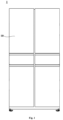
- a refrigerator 1 of the embodiment may generally include a refrigerator body 10.
- the refrigerator body 10 may include a housing, a liner, a heat insulation layer and other accessories.
- the housing is an outer layer structure of the refrigerator 1, and protects the whole refrigerator 1.
- the heat insulation layer is added between the housing and the liner of the refrigerator body 10, and the heat insulation layer is generally made by means of a foaming process.
- the liner at least includes a bottom liner 100, which may generally be a freezing liner.
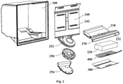
- a cooling chamber 140 is provided at the bottom of the bottom liner 100 of the refrigerator 1 of the embodiment, and an evaporator 220 is provided inside the cooling chamber 140 and supplies cold to the refrigerator 1.
- a separation cover plate 210 is provided on the lower portion of the bottom liner 100, and transversely provided inside the bottom liner 100 to separate the bottom liner 100 into the cooling chamber 140 and a freezing compartment 160 located above the cooling chamber 140.
- the evaporator 220 in the embodiment is provided on the lower portion of the bottom liner 100.
- Such a manner may avoid the reduction of depth of the freezing compartment due to the occupation of a rear space of the freezing compartment by an evaporator in a traditional refrigerator.
- it is especially important to increase the depth dimension of the freezing compartment when its transverse dimension is small.
- the space utilization of the refrigerator 1 is improved, and objects that are large and difficult to be divided are stored advantageously.
- the freezing compartment on the lowest portion has a low position, a user needs to bend down significantly or squat down to pick up and place objects in the freezing compartment.
- the lower space of the bottom liner 100 is occupied by the cooling chamber 140, and thus the height of the freezing compartment 160 above the cooling chamber 140 is raised, which reduces the degree of bending down when the user picks up and places the objects in the freezing compartment 160, thereby improving the user experience of the user.
- the evaporator 220 is arranged on the front portion of the cooling chamber 140, and obliquely provided in the cooling chamber 140.
- This mode breaks through the technical shackle that, in the prior art, an evaporator needs to be placed horizontally to reduce the depth dimension.
- oblique placement of the flat cuboid evaporator 220 may increase a length in the front-back direction, it makes other components inside the cooling chamber 140 arranged more reasonably, and it is verified from actual analysis of an air flow field that air circulation efficiency is higher, and water drainage is smoother.
- the layout of oblique placement of the evaporator 220 is one of the main technical improvements made in the embodiment.
- the inclination angle of the evaporator 220 is set within a range from 7 to 8 degrees, e.g., 7 degrees, 7.5 degrees and 8 degrees, preferably 7.5 degrees.
- the refrigerator 1 may also include an air supply assembly.
- the air supply assembly is provided behind the evaporator 220.
- the air supply assembly may include a centrifugal fan and an air supply duct 150.
- the centrifugal fan is obliquely provided behind the evaporator 220, with its suction inlet facing towards a front lower portion and its air outlet facing towards a rear portion, and is configured to enable the formation of a refrigeration air flow supplied towards the freezing compartment 160 via the evaporator 220.
- the air supply duct 150 communicates with the air outlet of the centrifugal fan and extends upwards, and is configured to convey an air flow discharged by the centrifugal fan to the freezing compartment 160.
- a proportion of a horizontal distance between the front end of the centrifugal fan and the evaporator 220 to the depth dimension of the refrigerator body 10 in the front-back direction is less than 4.5%. For example, the proportion is set to 4.3%.
- the refrigerator 1 may also include an air duct back plate 240.
- the air duct back plate 240 is provided in front of the rear wall of the bottom liner 100 and may be roughly parallel to the rear wall of the bottom liner 100, so as to define the air supply duct 150 together with the rear wall of the bottom liner 100.
- the air supply duct 150 communicates with the air outlet of the centrifugal fan and extends upwards.
- At least one air supply outlet 242 is formed in the air duct back plate 240.
- the air supply outlet 242 is configured to make the air supply duct 150 communicate with the freezing compartment 160.
- the air supply duct 150 communicates with the cooling chamber 140, and the separation cover plate 210 serves as a separation portion of the cooling chamber 140, thus the air duct back plate 240 may be connected with separation cover plate 210 in an abutting manner, so as to play a role in sealing a gap between the cooling chamber 140 and the air supply duct 150.
- the refrigeration fan may also be a centrifugal fan.
- the refrigeration fan may also include fan blades 250, a fan upper cover 252 and a fan bottom shell 254.
- the fan upper cover 252 obliquely extends downwards from the lower end of the air duct back plate 240 into the cooling chamber 140.
- the fan bottom shell 254 covers the fan upper cover 252 and is fastened thereto.
- the fan blades 250 are provided inside a fan cavity (not shown in the figures) formed by the fan upper cover 252 and the fan bottom shell 254.
- the air duct back plate 240 and the fan upper cover 252 may also be configured as an integrally-formed piece, so as to simplify installation processes and reduce costs, and also enable the whole air duct structure to be more stable.
- the refrigerator 1 may also include a return air cover 230.
- the return air cover 230 is provided on the front portion of the cooling chamber 140.
- At least one front return air inlet 232 that makes the cooling chamber 140 communicate with the freezing compartment 160 is formed in the return air cover 230.
- the evaporator 220 inside the cooling chamber 140 conducts heat exchange with surrounding air, to reduce the temperature of the air to form a refrigeration air flow.
- the refrigeration air flow is discharged from the cooling chamber 140 to the air supply duct 150, and then enters the freezing compartment 160 from the air supply outlet 242 in the air duct back plate 240, so as to conduct heat exchange with air in the freezing compartment 160 to reduce the temperature of the freezing compartment 160.
- the refrigeration air flow may flow back to the cooling chamber 140 via the front return air inlet 232 in the return air cover 230 after heat exchange to continue to conduct heat exchange with the evaporator 220, thereby forming a circulating air flow path.
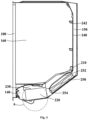
- a water receiving tank 1241 is formed on the bottom wall of the bottom liner 100, and a water drainage outlet 1241a is formed at the bottom of the water receiving tank 1241;
- the evaporator 1 also includes a water receiving tray 300 and a heating wire 400;
- the water receiving tray 300 is provided between the evaporator 220 and the bottom wall of the bottom liner 100, and is configured to receive water on the evaporator 220, and a plurality of through holes 322 are formed in a region of the water receiving tray 300 facing towards the water receiving tank 1241;
- the heating wire 400 is provided between the water receiving tray 300 and the evaporator 220 in a coiled manner, and is configured to provide heat for defrosting of the evaporator 220, and the heating wire 400 has an extension portion 412 extending to the water receiving tank 1241 through the through holes 322.
- the heating wire 400 is provided between the water receiving tray 300 and the evaporator 200 in the coiled manner, and may heat the evaporator 220 at intervals according to certain parameters to melt frost on the evaporator 220. For instance, when a compressor of the refrigerator 1 starts to work, the temperature of the evaporator 220 is reduced, a large amount of condensed water or defrosting water is produced at this time, and the heating wire 400 is started to conduct defrosting. Of course, starting and stopping of the heating wire 400 may also be controlled by other control logics, and in order not to obscure the invention point of the invention, it will not be described in detail herein.
- the water receiving tray 300 is provided between the evaporator 220 and the bottom wall of the bottom liner 100. After the defrost on the evaporator 220 is melted by the heating wire 400, the water receiving tray 300 may receive and collect the defrosting water, and divert the defrosting water into the water receiving tank 1241 on the bottom wall of the bottom liner 100.
- the water drainage outlet 1241a is formed at the bottom of the water receiving tank 1241.
- the water drainage outlet 1241a may generally communicate the water receiving tank 1241 with a compressor compartment located below the rear side of the bottom liner 100 to evaporate the defrosting water in the compressor compartment, thus preventing the defrosting water from dripping onto other components of the refrigerator 1 and causing a fault.
- the water drainage outlet 1241a is located at the bottom of the water receiving tank 1241.
- the heating wire 400 is provided between the water receiving tray 300 and the evaporator 220. In other words, there is a certain distance between the water drainage outlet 1241a and the heating wire 400, and there is also the water receiving tray 300 spaced between them, which may cause the situation that some large-volume ice cannot be melted by the heating wire 400 in time when falling in the water drainage outlet 1241a, resulting in blocking of the water drainage outlet 1241a and disadvantageous water drainage.
- the plurality of through holes 322 are formed in the region of the water receiving tray 300 facing towards the water receiving tank 1241, and the heating wire 400 has the extension portion 412 extending to the water receiving tank 1241 through the through holes 322. At least part of the extension portion 412 is provided in the water receiving tank 1241, which may reduce the distance between the heating wire 400 and the water drainage outlet 1241a so that heat of the heating wire 400 can be transferred to the water drainage outlet 1241a in time to prevent the water drainage outlet 1241a from being blocked. Additionally, since the heating wire 400 is provided between the water receiving tray 300 and the evaporator 220, the extension portion 412 may define the position between the water receiving tray 300 and the heating wire 400 when extending to the water receiving tank 1241 through the through holes 322.
- extension portion prevents the water drainage outlet from being blocked, it may also avoid additional heating wires at the water drainage outlet, thus reducing the cost of the refrigerator.
- the extension portion 412 may be formed by bending the middle of the heating wire 400 towards the water receiving tray 300.
- the diameter of the heating wire 400 may be slightly smaller than the dimensions of the through holes 322 to allow the extension portion 412 to pass through the through holes 322.
- the diameter of the heating wire 400 may be 4.5 mm, and the widths of the through holes 322 may be 6 mm, etc., which will not be enumerated herein.
- the heating wire 400 may also be configured as an aluminum tube heating wire.
- the water receiving tray 300 may also be configured as an aluminum water receiving tray.
- the aluminum water receiving tray 300 mainly acts to effectively and quickly transfer the heat of the heating wire 400 to all portions of the evaporator 220 to increase the heating area of the evaporator 220, thereby improving the defrosting efficiency.
- the distance between the bottom end of the extension portion 412 and the water drainage outlet 1241a may also be configured as any numerical value within a range from 3 mm to 5 mm, e.g., 3 mm, 4 mm or 5 mm, so as to make the extension portion get close to the water drainage outlet 1241a to the greatest extent on the premise of not affecting the water drainage effect of the water drainage outlet 1241a to prevent the water drainage outlet 1241a from being blocked.
- the bottom wall of the bottom liner 100 may include a first oblique portion 122, a sunken portion 124, a second oblique portion 126 and a third oblique portion 128.
- the first oblique portion 122 is obliquely provided downwards from front to back from the front end of the bottom wall of the bottom liner 100.
- the sunken portion 124 is provided on the rear side of the first oblique portion 122, and is configured to incline upwards from a transverse middle to two sides to form the water receiving tank 1241 in the transverse middle.
- the second oblique portion 126 is obliquely provided upwards from front to back from the rear end of the water receiving tank 1241.
- the third oblique portion 128 is obliquely provided upwards from front to back from the rear end of the second oblique portion 126.
- the second oblique portion 126 is obliquely provided relative to the front end of the bottom wall of the bottom liner 100.
- the evaporator 220 may be directly or indirectly provided on the second oblique portion 126, and the water receiving tank 1241 is formed at the sunken portion 124 located on the lower side of the second oblique portion 126, which enables the defrosting water on the evaporator 220 to be smoothly discharged into the water receiving tank 1241 when the evaporator 220 is obliquely provided on the second oblique portion 126.
- the inclination angle of the third oblique portion 128 is greater than that of the second oblique portion 126, and the inclination angle of the third oblique portion 128 relative to the horizontal direction may also be set within a range from 36 to 37 degrees, e.g., 36 degrees, 36.5 degrees and 37 degrees, preferably 36.7 degrees.
- the water receiving tray 300 includes a front plate segment 310, a middle plate segment 320 and a rear plate segment 330.
- the front plate segment 310 is located at the front end of the water receiving tray 300, and a gap is formed between it and the first oblique portion 122;
- the middle plate segment 320 obliquely extends upwards from the rear end of the front plate segment 310, with its front portion being located above the water receiving tank 1241 and provided with the plurality of through holes 322 and its rear portion abutting against the second oblique portion 126;
- the rear plate segment 330 obliquely extends upwards from the rear end of the middle plate segment 320 and abuts against the third oblique portion 128.
- the evaporator 220 has an overall flat cuboid shape, and is provided on the middle plate segment 320, and the bottom of a front end of the evaporator abuts against the junction of the middle plate segment 320 and the front plate segment 310, such that the evaporator 220 is provided at the inclination angle of the second oblique portion 126 to achieve the technical effect of oblique provision of the evaporator 220 in the above embodiments.
- the front plate segment 310 may abut against the first oblique portion 122, the middle plate segment 320 obliquely extends upwards from the rear end of the front plate segment 310, and the rear plate segment 330 obliquely extends upwards from the rear end of the middle plate segment 320.
- the evaporator 220 When the evaporator 220 is provided on the middle plate segment 320, it may be completely enclosed by the front plate segment 310, the middle plate segment 320 and the rear plate segment 330 to collect the defrosting water on the evaporator 220 to the greatest extent.
- the evaporator 220 is provided on the middle plate segment 320, and the middle plate segment 320 obliquely extends upwards from the rear end of the front plate segment 310, with its front end being located above the water receiving tank 1241.
- the front end of the evaporator 220 is also inclined towards the water receiving tank 1241, which may also reduce the distance between the front portion of the evaporator 220 and the water receiving tank 1241, thus reducing the distance between the whole heating wire 400 and the water receiving tank 1241.
- it is precisely because of the cooperation of the modes of the extension portion 412 and oblique provision of the evaporator 220 that the distance between the heating wire 400 and the water receiving tank 1241 is reduced to heat the water drainage outlet 1241a.
- the first oblique portion 122 may also form a protrusion portion 180, and the front plate segment 310 may lean against the protrusion portion, such that a gap is formed between the front plate segment 310 and the first oblique portion 122.
- the gap enables the water receiving tank 1241 to communicate with the cooling chamber 140 to keep the pressure of the water receiving tank 1241 equal to that of the cooling chamber 140, which is beneficial to water drainage.
- the distance between the front plate segment 310 and the first oblique portion 122 may also be configured as any numerical value within a range from 20 mm to 45 mm, e.g., 20 mm, 30 mm or 45 mm.
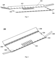
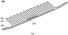
- the heating wire 400 includes a plurality of parallel sections 410 and a plurality of connection sections 420.
- the plurality of parallel sections 410 are parallelly provided at intervals relative to the transverse direction of the refrigerator 1, and the extension portion 412 is formed on the parallel sections 410.
- Each connection section 420 is provided between the ends on a same side of adjacent two parallel sections 410 in a bent extension manner to sequentially connect the plurality of parallel sections 410 in series.
- the heating wire 400 in the embodiment is provided in a manner of being coiled in an S shape, and the number of the parallel sections 410 and the distance between every two adjacent parallel sections 410 may be configured according to the area of the evaporator 220, such that the evaporator 220 may be evenly heated.
- the extension portion 412 may be formed by downwards bending the parallel sections 410, so as to protrude from the surface of the heating wire 400 and extend downwards to heat the water drainage outlet 1241a.
- the heating wire 400 may also include an expansion section 430.
- a middle portion of the expansion section 430 is provided abutting against the front plate segment 310 and the expansion section extends towards two sides to a position close to a side wall of the bottom liner 100 to conduct defrosting heating on a region in front of the evaporator 220. Ice falling from the top of the evaporator 220 in the defrosting process and ice appearing at a side return air inlet are melted and removed, which makes the action region of the heating wire more comprehensive and further guarantees smooth defrosting and water drainage.
- the side portions of the water receiving tray 300 may also extend towards the two sides to form expansion plate segments 340 to bear the expansion section 430.
- a plurality of limiting parts 350 are provided on the positions of the rear portion of the upper surface of the middle plate segment 320 facing towards the plurality of connection sections 420 to limit the connection sections 420.
- the limiting parts 350 may be a plurality of clamping grooves arched from the upper surface of the middle plate segment 320, and the connection sections 420 on the same side may extend into the clamping grooves, so as to limit the heating wire 400 and the middle plate segment 320 to simplify assembly processes.
- the limiting parts 350 have a shape of semisphere, which minimizes the impact on the refrigeration air flow.
- a plurality of water drainage holes 360 are also formed in the front portion of the upper surface of the middle plate segment 320 to discharge water received by the water receiving tray 300 into the water receiving tank 1241 through the water drainage holes 360 and gaps between the through holes 322 and the extension portion 412.
Landscapes
- Engineering & Computer Science (AREA)
- Chemical & Material Sciences (AREA)
- Combustion & Propulsion (AREA)
- Physics & Mathematics (AREA)
- Mechanical Engineering (AREA)
- Thermal Sciences (AREA)
- General Engineering & Computer Science (AREA)
- Removal Of Water From Condensation And Defrosting (AREA)
Applications Claiming Priority (3)
| Application Number | Priority Date | Filing Date | Title |
|---|---|---|---|
| CN202010832828.9A CN114076453A (zh) | 2020-08-18 | 2020-08-18 | 风冷冰箱 |
| EP21857554.6A EP4180749B1 (de) | 2020-08-18 | 2021-08-11 | Kühlschrank mit luftkühlung |
| PCT/CN2021/112100 WO2022037459A1 (zh) | 2020-08-18 | 2021-08-11 | 风冷冰箱 |
Related Parent Applications (2)
| Application Number | Title | Priority Date | Filing Date |
|---|---|---|---|
| EP21857554.6A Division EP4180749B1 (de) | 2020-08-18 | 2021-08-11 | Kühlschrank mit luftkühlung |
| EP21857554.6A Division-Into EP4180749B1 (de) | 2020-08-18 | 2021-08-11 | Kühlschrank mit luftkühlung |
Publications (2)
| Publication Number | Publication Date |
|---|---|
| EP4459208A2 true EP4459208A2 (de) | 2024-11-06 |
| EP4459208A3 EP4459208A3 (de) | 2025-01-22 |
Family
ID=80281337
Family Applications (2)
| Application Number | Title | Priority Date | Filing Date |
|---|---|---|---|
| EP24201405.8A Pending EP4459208A3 (de) | 2020-08-18 | 2021-08-11 | Luftgekühlter kühlschrank |
| EP21857554.6A Active EP4180749B1 (de) | 2020-08-18 | 2021-08-11 | Kühlschrank mit luftkühlung |
Family Applications After (1)
| Application Number | Title | Priority Date | Filing Date |
|---|---|---|---|
| EP21857554.6A Active EP4180749B1 (de) | 2020-08-18 | 2021-08-11 | Kühlschrank mit luftkühlung |
Country Status (5)
| Country | Link |
|---|---|
| US (2) | US12222153B2 (de) |
| EP (2) | EP4459208A3 (de) |
| CN (1) | CN114076453A (de) |
| AU (1) | AU2021326871B8 (de) |
| WO (1) | WO2022037459A1 (de) |
Families Citing this family (2)
| Publication number | Priority date | Publication date | Assignee | Title |
|---|---|---|---|---|
| CN114076453A (zh) * | 2020-08-18 | 2022-02-22 | 青岛海尔电冰箱有限公司 | 风冷冰箱 |
| US20250224170A1 (en) * | 2024-01-10 | 2025-07-10 | Haier Us Appliance Solutions, Inc. | Refrigerator appliance including a fresh food chamber cold wall |
Family Cites Families (25)
| Publication number | Priority date | Publication date | Assignee | Title |
|---|---|---|---|---|
| GB864574A (en) * | 1958-04-01 | 1961-04-06 | Gen Motors Corp | Improved refrigerator |
| US3099914A (en) * | 1961-12-29 | 1963-08-06 | Gen Electric | Refrigerating apparatus |
| US3224216A (en) * | 1964-09-03 | 1965-12-21 | Borg Warner | Refrigerator defrost tray |
| JPS5323973Y2 (de) * | 1973-09-13 | 1978-06-20 | ||
| JPS5710398Y2 (de) * | 1977-06-03 | 1982-02-27 | ||
| JPS6059068U (ja) * | 1983-09-27 | 1985-04-24 | 株式会社東芝 | 冷蔵庫 |
| JPS6062579A (ja) * | 1984-07-27 | 1985-04-10 | 株式会社日立製作所 | 冷蔵庫 |
| JP2002267332A (ja) | 2001-03-12 | 2002-09-18 | Matsushita Refrig Co Ltd | 冷蔵庫 |
| JP4653749B2 (ja) * | 2004-08-04 | 2011-03-16 | ホシザキ電機株式会社 | 冷却貯蔵庫 |
| KR20070062356A (ko) * | 2005-12-12 | 2007-06-15 | 주식회사 대우일렉트로닉스 | 냉장고의 증발기용 제상히터 |
| DE102006015994A1 (de) * | 2006-04-05 | 2007-10-11 | BSH Bosch und Siemens Hausgeräte GmbH | Kältegerät mit Abtauheizung |
| KR101404342B1 (ko) | 2007-07-12 | 2014-06-09 | 엘지전자 주식회사 | 냉장고 |
| KR20100043666A (ko) * | 2008-10-20 | 2010-04-29 | 주식회사 나노솔루션 | 증발장치 |
| CN203454542U (zh) | 2013-06-20 | 2014-02-26 | 合肥华凌股份有限公司 | 冰箱及其接水盘组件 |
| KR20180011691A (ko) | 2016-07-25 | 2018-02-02 | 엘지전자 주식회사 | 증발기 유닛 및 이를 구비한 냉장고 |
| CN109708358B (zh) | 2018-06-26 | 2021-06-15 | 重庆海尔制冷电器有限公司 | 用于冰箱的制冷装置及具有其的冰箱 |
| CN109373680A (zh) * | 2018-10-30 | 2019-02-22 | 合肥美的电冰箱有限公司 | 制冰机冰箱用接水盘、制冰机和冰箱 |
| CN109458782A (zh) * | 2018-12-20 | 2019-03-12 | 湖北美的电冰箱有限公司 | 冰箱 |
| CN209893735U (zh) * | 2019-02-26 | 2020-01-03 | 青岛海尔电冰箱有限公司 | 排水口设置有过滤板的冰箱 |
| CN209893753U (zh) | 2019-02-26 | 2020-01-03 | 青岛海尔电冰箱有限公司 | 加热丝置于蒸发器中部的冰箱 |
| CN210036003U (zh) * | 2019-04-26 | 2020-02-07 | 青岛海尔特种电冰箱有限公司 | 蒸发器与接水盘相匹配的冰箱 |
| US11137194B2 (en) * | 2019-07-22 | 2021-10-05 | Electrolux Home Products, Inc. | Contact defrost heater for bottom mount to evaporator |
| CN210832696U (zh) | 2019-09-12 | 2020-06-23 | 青岛海尔电冰箱有限公司 | 冰箱 |
| CN110953806A (zh) | 2019-12-17 | 2020-04-03 | 珠海格力电器股份有限公司 | 具有防堵结构的换热器组件及冰箱 |
| CN114076453A (zh) * | 2020-08-18 | 2022-02-22 | 青岛海尔电冰箱有限公司 | 风冷冰箱 |
-
2020
- 2020-08-18 CN CN202010832828.9A patent/CN114076453A/zh active Pending
-
2021
- 2021-08-11 AU AU2021326871A patent/AU2021326871B8/en active Active
- 2021-08-11 WO PCT/CN2021/112100 patent/WO2022037459A1/zh not_active Ceased
- 2021-08-11 US US18/020,986 patent/US12222153B2/en active Active
- 2021-08-11 EP EP24201405.8A patent/EP4459208A3/de active Pending
- 2021-08-11 EP EP21857554.6A patent/EP4180749B1/de active Active
-
2025
- 2025-01-07 US US19/012,166 patent/US20250146735A1/en active Pending
Also Published As
| Publication number | Publication date |
|---|---|
| US20250146735A1 (en) | 2025-05-08 |
| US20230288126A1 (en) | 2023-09-14 |
| CN114076453A (zh) | 2022-02-22 |
| EP4180749A1 (de) | 2023-05-17 |
| EP4459208A3 (de) | 2025-01-22 |
| AU2021326871B2 (en) | 2024-05-09 |
| AU2021326871A1 (en) | 2023-03-16 |
| AU2021326871B8 (en) | 2024-06-13 |
| EP4180749A4 (de) | 2024-01-10 |
| EP4180749B1 (de) | 2024-10-23 |
| WO2022037459A1 (zh) | 2022-02-24 |
| US12222153B2 (en) | 2025-02-11 |
Similar Documents
| Publication | Publication Date | Title |
|---|---|---|
| US20250146735A1 (en) | Air-cooled refrigerator | |
| US11333424B2 (en) | Refrigerator | |
| CN107883645B (zh) | 冰箱 | |
| CN111473578A (zh) | 冰箱 | |
| CN110285630A (zh) | 冰箱 | |
| JP2004085070A (ja) | 冷蔵庫 | |
| EP4174410B1 (de) | Luftgekühlter kühlschrank | |
| CN112129033A (zh) | 冰箱的接水盘、冰箱的风道组件及冰箱 | |
| CN222364234U (zh) | 制冷电器 | |
| US10371434B2 (en) | No-frost refrigeration device | |
| CN216114890U (zh) | 冰箱 | |
| CN111609628B (zh) | 排水口设置有过滤板的冰箱 | |
| US12173953B2 (en) | Refrigerator | |
| CN209893735U (zh) | 排水口设置有过滤板的冰箱 | |
| CN221992160U (zh) | 制冷电器 | |
| CN222480849U (zh) | 制冷设备 | |
| CN222504486U (zh) | 制冷设备 | |
| CN221924157U (zh) | 排水组件、风道组件和制冷设备 | |
| CN222165338U (zh) | 冷柜 | |
| CN222165335U (zh) | 制冷设备 | |
| CN222865316U (zh) | 制冷电器 | |
| CN222165337U (zh) | 冷柜 | |
| KR20120029255A (ko) | 냉장고 | |
| CN222418117U (zh) | 制冷电器 | |
| CN118189518A (zh) | 用于冷柜的内胆和冷柜 |
Legal Events
| Date | Code | Title | Description |
|---|---|---|---|
| PUAI | Public reference made under article 153(3) epc to a published international application that has entered the european phase |
Free format text: ORIGINAL CODE: 0009012 |
|
| STAA | Information on the status of an ep patent application or granted ep patent |
Free format text: STATUS: THE APPLICATION HAS BEEN PUBLISHED |
|
| AC | Divisional application: reference to earlier application |
Ref document number: 4180749 Country of ref document: EP Kind code of ref document: P |
|
| AK | Designated contracting states |
Kind code of ref document: A2 Designated state(s): AL AT BE BG CH CY CZ DE DK EE ES FI FR GB GR HR HU IE IS IT LI LT LU LV MC MK MT NL NO PL PT RO RS SE SI SK SM TR |
|
| REG | Reference to a national code |
Ref country code: DE Ref legal event code: R079 Free format text: PREVIOUS MAIN CLASS: F25D0023060000 Ipc: F25D0011020000 |
|
| PUAL | Search report despatched |
Free format text: ORIGINAL CODE: 0009013 |
|
| AK | Designated contracting states |
Kind code of ref document: A3 Designated state(s): AL AT BE BG CH CY CZ DE DK EE ES FI FR GB GR HR HU IE IS IT LI LT LU LV MC MK MT NL NO PL PT RO RS SE SI SK SM TR |
|
| RIC1 | Information provided on ipc code assigned before grant |
Ipc: F25D 23/06 20060101ALI20241217BHEP Ipc: F25D 21/14 20060101ALI20241217BHEP Ipc: F25D 21/08 20060101ALI20241217BHEP Ipc: F25D 11/02 20060101AFI20241217BHEP |
|
| STAA | Information on the status of an ep patent application or granted ep patent |
Free format text: STATUS: REQUEST FOR EXAMINATION WAS MADE |
|
| 17P | Request for examination filed |
Effective date: 20250704 |