EP4459170A1 - Arrangement for attachment of devices to a surface and method for attaching an arrangement to a surface - Google Patents
Arrangement for attachment of devices to a surface and method for attaching an arrangement to a surface Download PDFInfo
- Publication number
- EP4459170A1 EP4459170A1 EP23171100.3A EP23171100A EP4459170A1 EP 4459170 A1 EP4459170 A1 EP 4459170A1 EP 23171100 A EP23171100 A EP 23171100A EP 4459170 A1 EP4459170 A1 EP 4459170A1
- Authority
- EP
- European Patent Office
- Prior art keywords
- mounting bracket
- connector end
- male connector
- recess
- female connector
- Prior art date
- Legal status (The legal status is an assumption and is not a legal conclusion. Google has not performed a legal analysis and makes no representation as to the accuracy of the status listed.)
- Granted
Links
Images





Classifications
-
- F—MECHANICAL ENGINEERING; LIGHTING; HEATING; WEAPONS; BLASTING
- F16—ENGINEERING ELEMENTS AND UNITS; GENERAL MEASURES FOR PRODUCING AND MAINTAINING EFFECTIVE FUNCTIONING OF MACHINES OR INSTALLATIONS; THERMAL INSULATION IN GENERAL
- F16M—FRAMES, CASINGS OR BEDS OF ENGINES, MACHINES OR APPARATUS, NOT SPECIFIC TO ENGINES, MACHINES OR APPARATUS PROVIDED FOR ELSEWHERE; STANDS; SUPPORTS
- F16M13/00—Other supports for positioning apparatus or articles; Means for steadying hand-held apparatus or articles
- F16M13/02—Other supports for positioning apparatus or articles; Means for steadying hand-held apparatus or articles for supporting on, or attaching to, an object, e.g. tree, gate, window-frame, cycle
-
- F—MECHANICAL ENGINEERING; LIGHTING; HEATING; WEAPONS; BLASTING
- F16—ENGINEERING ELEMENTS AND UNITS; GENERAL MEASURES FOR PRODUCING AND MAINTAINING EFFECTIVE FUNCTIONING OF MACHINES OR INSTALLATIONS; THERMAL INSULATION IN GENERAL
- F16M—FRAMES, CASINGS OR BEDS OF ENGINES, MACHINES OR APPARATUS, NOT SPECIFIC TO ENGINES, MACHINES OR APPARATUS PROVIDED FOR ELSEWHERE; STANDS; SUPPORTS
- F16M13/00—Other supports for positioning apparatus or articles; Means for steadying hand-held apparatus or articles
- F16M13/02—Other supports for positioning apparatus or articles; Means for steadying hand-held apparatus or articles for supporting on, or attaching to, an object, e.g. tree, gate, window-frame, cycle
- F16M13/022—Other supports for positioning apparatus or articles; Means for steadying hand-held apparatus or articles for supporting on, or attaching to, an object, e.g. tree, gate, window-frame, cycle repositionable
-
- A—HUMAN NECESSITIES
- A47—FURNITURE; DOMESTIC ARTICLES OR APPLIANCES; COFFEE MILLS; SPICE MILLS; SUCTION CLEANERS IN GENERAL
- A47B—TABLES; DESKS; OFFICE FURNITURE; CABINETS; DRAWERS; GENERAL DETAILS OF FURNITURE
- A47B95/00—Fittings for furniture
- A47B95/008—Suspension fittings for cabinets to be hung on walls
-
- A—HUMAN NECESSITIES
- A47—FURNITURE; DOMESTIC ARTICLES OR APPLIANCES; COFFEE MILLS; SPICE MILLS; SUCTION CLEANERS IN GENERAL
- A47B—TABLES; DESKS; OFFICE FURNITURE; CABINETS; DRAWERS; GENERAL DETAILS OF FURNITURE
- A47B96/00—Details of cabinets, racks or shelf units not covered by a single one of groups A47B43/00 - A47B95/00; General details of furniture
- A47B96/06—Brackets or similar supporting means for cabinets, racks or shelves
-
- A—HUMAN NECESSITIES
- A47—FURNITURE; DOMESTIC ARTICLES OR APPLIANCES; COFFEE MILLS; SPICE MILLS; SUCTION CLEANERS IN GENERAL
- A47G—HOUSEHOLD OR TABLE EQUIPMENT
- A47G1/00—Mirrors; Picture frames or the like, e.g. provided with heating, lighting or ventilating means
- A47G1/16—Devices for hanging or supporting pictures, mirrors, or the like
- A47G1/1606—Devices for hanging or supporting pictures, mirrors, or the like comprising a wall member cooperating with a corresponding picture member
-
- E—FIXED CONSTRUCTIONS
- E04—BUILDING
- E04F—FINISHING WORK ON BUILDINGS, e.g. STAIRS, FLOORS
- E04F13/00—Coverings or linings, e.g. for walls or ceilings
- E04F13/07—Coverings or linings, e.g. for walls or ceilings composed of covering or lining elements; Sub-structures therefor; Fastening means therefor
- E04F13/08—Coverings or linings, e.g. for walls or ceilings composed of covering or lining elements; Sub-structures therefor; Fastening means therefor composed of a plurality of similar covering or lining elements
- E04F13/0801—Separate fastening elements
-
- E—FIXED CONSTRUCTIONS
- E04—BUILDING
- E04F—FINISHING WORK ON BUILDINGS, e.g. STAIRS, FLOORS
- E04F13/00—Coverings or linings, e.g. for walls or ceilings
- E04F13/07—Coverings or linings, e.g. for walls or ceilings composed of covering or lining elements; Sub-structures therefor; Fastening means therefor
- E04F13/08—Coverings or linings, e.g. for walls or ceilings composed of covering or lining elements; Sub-structures therefor; Fastening means therefor composed of a plurality of similar covering or lining elements
- E04F13/0801—Separate fastening elements
- E04F13/0803—Separate fastening elements with load-supporting elongated furring elements between wall and covering elements
- E04F13/081—Separate fastening elements with load-supporting elongated furring elements between wall and covering elements with additional fastening elements between furring elements and covering elements
- E04F13/0821—Separate fastening elements with load-supporting elongated furring elements between wall and covering elements with additional fastening elements between furring elements and covering elements the additional fastening elements located in-between two adjacent covering elements
-
- E—FIXED CONSTRUCTIONS
- E04—BUILDING
- E04F—FINISHING WORK ON BUILDINGS, e.g. STAIRS, FLOORS
- E04F13/00—Coverings or linings, e.g. for walls or ceilings
- E04F13/07—Coverings or linings, e.g. for walls or ceilings composed of covering or lining elements; Sub-structures therefor; Fastening means therefor
- E04F13/08—Coverings or linings, e.g. for walls or ceilings composed of covering or lining elements; Sub-structures therefor; Fastening means therefor composed of a plurality of similar covering or lining elements
- E04F13/0801—Separate fastening elements
- E04F13/0832—Separate fastening elements without load-supporting elongated furring elements between wall and covering elements
- E04F13/0833—Separate fastening elements without load-supporting elongated furring elements between wall and covering elements not adjustable
- E04F13/0835—Separate fastening elements without load-supporting elongated furring elements between wall and covering elements not adjustable the fastening elements extending into the back side of the covering elements
-
- E—FIXED CONSTRUCTIONS
- E04—BUILDING
- E04F—FINISHING WORK ON BUILDINGS, e.g. STAIRS, FLOORS
- E04F13/00—Coverings or linings, e.g. for walls or ceilings
- E04F13/07—Coverings or linings, e.g. for walls or ceilings composed of covering or lining elements; Sub-structures therefor; Fastening means therefor
- E04F13/21—Fastening means specially adapted for covering or lining elements
- E04F13/24—Hidden fastening means on the rear of the covering or lining elements
-
- F—MECHANICAL ENGINEERING; LIGHTING; HEATING; WEAPONS; BLASTING
- F16—ENGINEERING ELEMENTS AND UNITS; GENERAL MEASURES FOR PRODUCING AND MAINTAINING EFFECTIVE FUNCTIONING OF MACHINES OR INSTALLATIONS; THERMAL INSULATION IN GENERAL
- F16B—DEVICES FOR FASTENING OR SECURING CONSTRUCTIONAL ELEMENTS OR MACHINE PARTS TOGETHER, e.g. NAILS, BOLTS, CIRCLIPS, CLAMPS, CLIPS OR WEDGES; JOINTS OR JOINTING
- F16B1/00—Devices for securing together, or preventing relative movement between, constructional elements or machine parts
- F16B1/02—Means for securing elements of mechanisms after operation
-
- F—MECHANICAL ENGINEERING; LIGHTING; HEATING; WEAPONS; BLASTING
- F16—ENGINEERING ELEMENTS AND UNITS; GENERAL MEASURES FOR PRODUCING AND MAINTAINING EFFECTIVE FUNCTIONING OF MACHINES OR INSTALLATIONS; THERMAL INSULATION IN GENERAL
- F16B—DEVICES FOR FASTENING OR SECURING CONSTRUCTIONAL ELEMENTS OR MACHINE PARTS TOGETHER, e.g. NAILS, BOLTS, CIRCLIPS, CLAMPS, CLIPS OR WEDGES; JOINTS OR JOINTING
- F16B5/00—Joining sheets or plates, e.g. panels, to one another or to strips or bars parallel to them
- F16B5/06—Joining sheets or plates, e.g. panels, to one another or to strips or bars parallel to them by means of clamps or clips
- F16B5/0607—Joining sheets or plates, e.g. panels, to one another or to strips or bars parallel to them by means of clamps or clips joining sheets or plates to each other
- F16B5/0621—Joining sheets or plates, e.g. panels, to one another or to strips or bars parallel to them by means of clamps or clips joining sheets or plates to each other in parallel relationship
- F16B5/0635—Joining sheets or plates, e.g. panels, to one another or to strips or bars parallel to them by means of clamps or clips joining sheets or plates to each other in parallel relationship fastened over the edges of the sheets or plates
-
- F—MECHANICAL ENGINEERING; LIGHTING; HEATING; WEAPONS; BLASTING
- F16—ENGINEERING ELEMENTS AND UNITS; GENERAL MEASURES FOR PRODUCING AND MAINTAINING EFFECTIVE FUNCTIONING OF MACHINES OR INSTALLATIONS; THERMAL INSULATION IN GENERAL
- F16M—FRAMES, CASINGS OR BEDS OF ENGINES, MACHINES OR APPARATUS, NOT SPECIFIC TO ENGINES, MACHINES OR APPARATUS PROVIDED FOR ELSEWHERE; STANDS; SUPPORTS
- F16M11/00—Stands or trestles as supports for apparatus or articles placed thereon ; Stands for scientific apparatus such as gravitational force meters
- F16M11/02—Heads
- F16M11/04—Means for attachment of apparatus; Means allowing adjustment of the apparatus relatively to the stand
- F16M11/041—Allowing quick release of the apparatus
-
- F—MECHANICAL ENGINEERING; LIGHTING; HEATING; WEAPONS; BLASTING
- F16—ENGINEERING ELEMENTS AND UNITS; GENERAL MEASURES FOR PRODUCING AND MAINTAINING EFFECTIVE FUNCTIONING OF MACHINES OR INSTALLATIONS; THERMAL INSULATION IN GENERAL
- F16M—FRAMES, CASINGS OR BEDS OF ENGINES, MACHINES OR APPARATUS, NOT SPECIFIC TO ENGINES, MACHINES OR APPARATUS PROVIDED FOR ELSEWHERE; STANDS; SUPPORTS
- F16M11/00—Stands or trestles as supports for apparatus or articles placed thereon ; Stands for scientific apparatus such as gravitational force meters
- F16M11/20—Undercarriages with or without wheels
- F16M11/22—Undercarriages with or without wheels with approximately constant height, e.g. with constant length of column or of legs
-
- H—ELECTRICITY
- H02—GENERATION; CONVERSION OR DISTRIBUTION OF ELECTRIC POWER
- H02B—BOARDS, SUBSTATIONS OR SWITCHING ARRANGEMENTS FOR THE SUPPLY OR DISTRIBUTION OF ELECTRIC POWER
- H02B1/00—Frameworks, boards, panels, desks, casings; Details of substations or switching arrangements
- H02B1/26—Casings; Parts thereof or accessories therefor
- H02B1/40—Wall-mounted casings; Parts thereof or accessories therefor
-
- H—ELECTRICITY
- H02—GENERATION; CONVERSION OR DISTRIBUTION OF ELECTRIC POWER
- H02G—INSTALLATION OF ELECTRIC CABLES OR LINES, OR OF COMBINED OPTICAL AND ELECTRIC CABLES OR LINES
- H02G3/00—Installations of electric cables or lines or protective tubing therefor in or on buildings, equivalent structures or vehicles
- H02G3/02—Details
- H02G3/08—Distribution boxes; Connection or junction boxes
-
- F—MECHANICAL ENGINEERING; LIGHTING; HEATING; WEAPONS; BLASTING
- F16—ENGINEERING ELEMENTS AND UNITS; GENERAL MEASURES FOR PRODUCING AND MAINTAINING EFFECTIVE FUNCTIONING OF MACHINES OR INSTALLATIONS; THERMAL INSULATION IN GENERAL
- F16B—DEVICES FOR FASTENING OR SECURING CONSTRUCTIONAL ELEMENTS OR MACHINE PARTS TOGETHER, e.g. NAILS, BOLTS, CIRCLIPS, CLAMPS, CLIPS OR WEDGES; JOINTS OR JOINTING
- F16B2200/00—Constructional details of connections not covered for in other groups of this subclass
- F16B2200/30—Dovetail-like connections
-
- F—MECHANICAL ENGINEERING; LIGHTING; HEATING; WEAPONS; BLASTING
- F16—ENGINEERING ELEMENTS AND UNITS; GENERAL MEASURES FOR PRODUCING AND MAINTAINING EFFECTIVE FUNCTIONING OF MACHINES OR INSTALLATIONS; THERMAL INSULATION IN GENERAL
- F16B—DEVICES FOR FASTENING OR SECURING CONSTRUCTIONAL ELEMENTS OR MACHINE PARTS TOGETHER, e.g. NAILS, BOLTS, CIRCLIPS, CLAMPS, CLIPS OR WEDGES; JOINTS OR JOINTING
- F16B5/00—Joining sheets or plates, e.g. panels, to one another or to strips or bars parallel to them
- F16B5/0004—Joining sheets, plates or panels in abutting relationship
- F16B5/0008—Joining sheets, plates or panels in abutting relationship by moving the sheets, plates or panels substantially in their own plane, perpendicular to the abutting edge
- F16B5/0012—Joining sheets, plates or panels in abutting relationship by moving the sheets, plates or panels substantially in their own plane, perpendicular to the abutting edge a tongue on the edge of one sheet, plate or panel co-operating with a groove in the edge of another sheet, plate or panel
-
- F—MECHANICAL ENGINEERING; LIGHTING; HEATING; WEAPONS; BLASTING
- F16—ENGINEERING ELEMENTS AND UNITS; GENERAL MEASURES FOR PRODUCING AND MAINTAINING EFFECTIVE FUNCTIONING OF MACHINES OR INSTALLATIONS; THERMAL INSULATION IN GENERAL
- F16B—DEVICES FOR FASTENING OR SECURING CONSTRUCTIONAL ELEMENTS OR MACHINE PARTS TOGETHER, e.g. NAILS, BOLTS, CIRCLIPS, CLAMPS, CLIPS OR WEDGES; JOINTS OR JOINTING
- F16B5/00—Joining sheets or plates, e.g. panels, to one another or to strips or bars parallel to them
- F16B5/02—Joining sheets or plates, e.g. panels, to one another or to strips or bars parallel to them by means of fastening members using screw-thread
- F16B5/025—Joining sheets or plates, e.g. panels, to one another or to strips or bars parallel to them by means of fastening members using screw-thread specially designed to compensate for misalignement or to eliminate unwanted play
-
- G—PHYSICS
- G09—EDUCATION; CRYPTOGRAPHY; DISPLAY; ADVERTISING; SEALS
- G09G—ARRANGEMENTS OR CIRCUITS FOR CONTROL OF INDICATING DEVICES USING STATIC MEANS TO PRESENT VARIABLE INFORMATION
- G09G2300/00—Aspects of the constitution of display devices
- G09G2300/02—Composition of display devices
- G09G2300/026—Video wall, i.e. juxtaposition of a plurality of screens to create a display screen of bigger dimensions
-
- H—ELECTRICITY
- H02—GENERATION; CONVERSION OR DISTRIBUTION OF ELECTRIC POWER
- H02G—INSTALLATION OF ELECTRIC CABLES OR LINES, OR OF COMBINED OPTICAL AND ELECTRIC CABLES OR LINES
- H02G3/00—Installations of electric cables or lines or protective tubing therefor in or on buildings, equivalent structures or vehicles
- H02G3/02—Details
- H02G3/08—Distribution boxes; Connection or junction boxes
- H02G3/10—Distribution boxes; Connection or junction boxes for surface mounting on a wall
Definitions
- the present invention relates to an arrangement for attachment of devices to a surface and a method for attaching such an arrangement to a surface.
- the devices may be arranged in one or more arrays, i.e. next to each other.
- the devices may for instance comprise electronic units, such as I/O relay modules for access control systems.
- mounting brackets are used for supporting the devices, which mounting brackets are attached to the surface, for instance by means of screws.
- CA2585947A1 such an arrangment for attachment of devices to a surface is disclosed.
- a further object is to provide a method for attaching such an arrangement to a surface.
- an arrangement for attachment of devices to a surface such as a wall
- the arrangement comprising at least one device, and for each device, at least two mounting brackets, wherein each device has a rear side provided with a recess for each mounting bracket associated to the device, wherein each mounting bracket has a male connector end and a female connector end, the male connector end being configured to be received by the female connector end of an adjoining mounting bracket associated to a neighbouring device, wherein each male connector end is provided with at least one through hole for receiving an attachment means, such as a screw, wherein each mounting bracket is insertable into its associated recess with an orientation in which the male connector end extends beyond a periphery of the device, and wherein each mounting bracket is insertable into its associated recess with an orientation in which the female connector end is accessible from the periphery of the device.
- the arrangement enables utilization of an already attached or mounted device when attaching or mounting a subsequent device, thereby facilitating and speeding up the process of attaching the arrangement to a surface.
- Each device has a rear side provided with recesses into which a respective mounting bracket is insertable with two possible orientations, one in which a male connector end of the mounting bracket extends beyond the periphery of the device and one in which the female connector end of the mounting bracket is accessible from the periphery of the device.
- each mounting bracket may be inserted into its respective recess of the first device with the orientation in which the male connector end extends beyond the periphery of the first device, thereby enabling attachment of the first device to the surface by means of an attachment means, such as a screw, by utilization of the through hole provided in said male connector end of each mounting bracket.
- one mounting bracket For mounting a second device of the arrangement as a neighbouring device to the first device, one mounting bracket may be inserted into its respective recess of the second device with the orientation in which the female connector end is accessible from the periphery of the second device, and one mounting bracket may be inserted into its respective recess of the second device with the orientation in which the male connector end extends beyond the periphery of the second device.
- the second device may be arranged next to the first device such that the male end connector of the adjoining mounting bracket of the first device is received by the female connector end of the mounting bracket having the orientation in which the female connector end is accessible from the periphery of the second device.
- the second device may be secured to the surface by means of an attachment means, such as a screw, by utilization of the through hole provided in said male connector end of the mounting bracket having the orientation in which the male connector end extends beyond the periphery of the second device.
- the arrangement makes it possible to mount devices flush against the surface, without adding a distance between the device and the surface, as is the case when mounting devices using known DIN rails.
- each mounting bracket may be provided with a male connector engagement surface and the female connector end of each mounting bracket may be provided with a female connector engagement surface, wherein the male connector engagement surface of the male connector end of each mounting bracket is configured to engage the female connector engagement surface of the female connector end of an adjoining mounting bracket associated to a neighbouring device such that movement of the neighbouring device is restricted when the male connector end is received by the female connector end of the adjoining mounting bracket.
- the female connector engagement surface and the male connector engagement surface may be chamfered.
- the male connector engagement surface of the male connector end of each mounting bracket may be configured to engage the female connector engagement surface of the female connector end of an adjoining mounting bracket associated to a neighbouring device such that the neighbouring device is pressed against the surface.
- each mounting bracket may be insertable into its associated recess with a snap fit.
- the mounting brackets may be easily and reliably connected to the at least one device.
- each mounting bracket may be provided with at least one abutment surface configured to engage its associated device in response to attaching the device to the surface by means of the attachment means, such as a screw, extending through the at least one through hole of the male connector end of the mounting bracket or in response to the male end connector of an adjoining mounting bracket of a neighbouring device being received by the female connector end of the mounting bracket such that the device is pressed against the surface.
- attachment means such as a screw
- each recess of each device may have an opening facing the periphery of the device such that the mounting bracket associated to the recess is slidingly insertable into the recess from a lateral side of the device.
- the recesses of each device may form at least one pair of oppositely arranged recesses.
- the arrangement of oppositely arranged recesses enables mounting several devices next to each other for forming of a row or column.
- each device may be rectangular in shape and have a first major surface; an opposing second major surface forming said rear side of the device; and four side edges forming said periphery of the device and extending between the first and second major surface.
- the recesses provided in the rear surface of each device may comprise a first recess arranged in a rear surface portion adjoining a first side edge of said four side edges of the device; and a second recess arranged in a rear surface portion adjoining a second side edge of said four side edges of the device, said second side edge being opposite to the first side edge.
- each device may further comprise a third recess arranged in a rear surface portion adjoining a third side edge of said four side edges of the device; and a fourth recess arranged in a rear surface portion adjoining a fourth side edge of said four side edges of the device, said third side edge being opposite to the fourth side edge.
- the provisions of recesses in the rear surface portions adjoining the first, second, third and fourth side edge enables attachment of the of devices on the surface for forming a row and/or column.
- the at least one device may comprise a device in the form of an electronic unit, such as a I/O relay module for an access control system.
- a method for attaching an arrangement to a surface comprising: providing an arrangement according to the first aspect of the present invention, inserting mounting brackets into the associated recesses of a first device of said at least one device with the orientation in which the male connector end of each mounting bracket extends beyond the periphery of the first device, and attaching the first device to the surface by means of an attachment means, such as a screw, extending through the at least one through hole of the male connector end of each mounting bracket.
- the method enables efficient attachment of the arrangement to the surface by arranging the mounting brackets of the first device with the orientation in which the male connector end of each mounting bracket extends beyond the periphery of the first device.
- the first device may be secured to the surface by means of the attachment means extending through the trough holes of the male connector end of each mounting bracket, while the male connector ends also may be utilized when attaching a subsequent a second device to the surface, next to the first device.
- the method may further comprise inserting mounting brackets into the associated recesses of a second device of said at least one device, wherein a first of the mounting brackets is inserted in its associated recess with the orientation in which the female connector end is accessible from the periphery of the second device and wherein a second of the mounting brackets is inserted in its associated recess with the orientation in which the male connector end extends beyond the periphery of the second device, arranging the second device next to the first device such that the male connector end of one of the mounting brackets of the first device is received by the female connector end of the first of the mounting brackets of the second device, and attaching the second device to the surface by means of an attachment means, such as a screw, extending through the at least one through hole of the male connector end of the second of the mounting brackets of the second device.
- an attachment means such as a screw
- the present invention relates to an arrangement 100, as illustrated for instance in Fig. 4a , for attachment of devices 1 to a surface 2, such as a wall.
- the arrangement 100 comprises at least one device 1 and for each device, at least two mounting brackets 3.
- the device 1 may be an electronic unit, such as an I/O relay module for an access control system.
- FIG. 1 An embodiment of a device 1 comprised in an arrangement in accordance with the present invention is shown in Fig. 1 and an embodiment of a mounting bracket 3 comprised in an arrangement in accordance with the present invention is shown in Figs. 2a and 2b , wherein Fig. 2a illustrates a bottom view and Fig. 2b illustrates a top view.
- the device 1 has a rear side 4 provided with a recess 5 for each mounting bracket 3 associated to the device 1.
- the rear side 4 is provided with two recesses 5.
- Each mounting bracket 3 is insertable into its associated recess 5.
- One of the recesses 5 is shown more in detail in the detached enlargement in Fig. 1 .
- Each recess 5 may have an opening 14 facing a periphery 10 of the device 1.
- the device 1 may be rectangular in shape and may have a first major surface15; an opposing second major surface 16 forming said rear side 4 of the device 1; and four side edges 17 forming said periphery 10 of the device 1 and extending between the first 15 and second major surface 16.
- the recesses 5 may form at least one pair of oppositely arranged recesses 5.
- the recesses 5 form a single pair of oppositely arranged recesses 5.
- the recesses 5 provided in the rear surface 4 of the shown device 1 comprise a first recess 5 arranged in a rear surface portion 18a adjoining a first side edge 17a of the four side edges 17 of the device 1; and a second recess 5 arranged in a rear surface portion 18b adjoining a second side edge 17b of said four side edges 17 of the device 1, said second side edge 17b being opposite to the first side edge 17a.
- the device 1 also may comprise a third recess (not shown) arranged in a rear surface portion 18c adjoining a third side edge 17c of said four side edges 17 of the device 1; and a fourth recess (not shown) arranged in a rear surface portion 18d adjoining a fourth side edge 17d of said four side edges 17 of the device 1, said third side edge 17c being opposite to the fourth side edge 17d.
- a third recess (not shown) arranged in a rear surface portion 18c adjoining a third side edge 17c of said four side edges 17 of the device 1
- a fourth recess (not shown) arranged in a rear surface portion 18d adjoining a fourth side edge 17d of said four side edges 17 of the device 1, said third side edge 17c being opposite to the fourth side edge 17d.
- Each recess 5 may comprise one or more grooves 18, each groove 18 being configured to receive a flange 19 of the mounting bracket 3 associated to the recess 5 when the mounting bracket 3 is inserted into said recess 5.
- the recess 5 is provided with two such grooves 18 arranged at opposed lateral sides of the recess 5. Consequently, the shown recess 5 is configured for reception of a mounting bracket 3 provided with two flanges 19.
- Each groove 18 may as in the illustrated embodiment partly be defined by a top surface 20.
- a bottom surface 21 of the recess 5 may be provided with one or more protrusions 22.
- the bottom surface 21 is provided with two such protrusions 22 arranged in a spaced apart manner.
- each recess 5 further comprises a projection 23 arranged at an end 24 of the recess 5.
- Each mounting bracket 3 comprises two spaced apart legs 25 connected by a bridging section 26 and a tongue extending 27 from the bridging section 26 in a direction opposite to the legs 25.
- the mounting bracket 3 may be made in one piece.
- Each mounting bracket 3 has a male connector end 6 and a female connector end 7.
- the male connector end 6 of each mounting bracket 3 is configured to be received by the female connector end 7 of an adjoining mounting bracket 3.
- the male connector end 6 is formed by the tongue 27 and the female connector end 7 is formed by the legs 25 and the bridging section 26.
- each mounting bracket 3 is provided with a male connector engagement surface 11 and the female connector end 7 of each mounting bracket 3 is provided with a female connector engagement surface 12.
- the mounting bracket 3 is provided with two such male connector engagement surfaces 11 and two such female connector engagement surfaces 12.
- the male connector engagement surface 11 and the female connector engagement surface 12 may as in the shown embodiment be chamfered.
- each mounting bracket 3 is provided with at least one through hole 8 for receiving an attachment means, such as a screw.
- the male connector end 6 is provided with two such through holes 8 which are countersunk.
- the male connector engagement surface 11 of the male connector end 6 of each mounting bracket 3 is configured to engage the female connector engagement surface 12 of the female connector end 7 of an adjoining mounting bracket 3 associated to a neighbouring device 1 such that movement of the neighbouring device 1 is restricted when the male connector end 6 is received by the female connector end 7 of the adjoining mounting bracket 3.
- the distal end 28 of the male connector end 6 of the mounting bracket 3 may be provided with a notch 29.
- the mounting bracket 3 may further be provided with a central dent 30 in a surface of the mounting bracket 3 configured to face away from the device 1 when the mounting bracket 3 is inserted into its associated recess 5.
- the mounting bracket 3 may further be provided with at least one abutment surface 13 configured to engage its associated device 1.
- the mounting bracket 3 comprises two opposing, lateral flanges 19, each flange 19 extending along a respective leg 25 of the mounting bracket 3 and comprising one such abutment surface 13.
- each leg 25 is further provided with an opening 31.
- Each leg 25 is further provided with a first and second guiding groove 32a, 32b extending in the longitudinal direction of the leg 25.
- the first and second guiding grooves 32a, 32b are provided in a surface of the mounting bracket 3 configured to face the device 1 when the mounting bracket 3 is inserted into its associated recess 5.
- the first guiding groove 32a extends from a male connector end side of the mounting bracket 3 with an upward slope towards the opening 31.
- the second guiding groove 32b extends from a female connector end side of the mounting bracket 3 with an upward slope towards the opening 31.
- each mounting bracket 3 is insertable into its associated recess 5 of the device 1.
- each mounting bracket 3 is insertable into its associated recess 5 with an orientation in which the male connector end 6 extends beyond the periphery 10 of the device 1 and with an orientation in which the female connector end 7 is accessible from the periphery 10 of the device 1.
- Each mounting bracket 3 is thus insertable into its recess 5 with two possible orientations.
- a device 1 of the type described above with reference to Fig. 1 is shown with a first mounting bracket 3 inserted into a first recess 5 of the device with an orientation in which the male connector end 6 extends beyond the periphery 10 of the device 1, and with a second mounting bracket 3 inserted into a second recess 5 of the device 1 with an orientation in which the female connector end 7 is accessible from the periphery 10 of the device 1.
- the mounting brackets 3 are of the type described above with reference to Figs. 2a, 2b .
- the device is depicted in a bottom view illustrating the rear side 4 of the device 1.
- each mounting bracket 3 is slidingly insertable into its associated recess 5 from a lateral side of the device 1 via the opening 14 in the recess 5 facing the periphery 10 of the device 1.
- Each mounting bracket 3 is insertable into its associated recess 5 with a snap fit.
- the protrusions 22 provided on the bottom surface 21 of each recess 5 cooperate with the guiding grooves 32a, 32b and openings 31 of the mounting bracket 3 for enabling said snap fit.
- the protrusions 22 of the first recess 5 will initially be received by the second guiding grooves 32b of the first mounting bracket 3 and then guided towards the openings 31 of the first mounting bracket 3 in response to insertion of the first mounting bracket 3 into the first recess 5.
- the protrusions 22 reach the openings 31, they will snap into the openings 31.
- the protrusions 22 of the second recess 5 will initially be received by the first guiding grooves 32a of the second mounting bracket 3 and then guided towards the opening 31 of the second mounting bracket 3 in response to inserting the second mounting bracket 3 into the second recess 5.
- the protrusions 22 reach the openings 31, they will snap into the openings 31.
- each mounting bracket 3 When each mounting bracket 3 is inserted into its associated recess 5, the two opposing lateral flanges 19 of the mounting bracket 3 are received by the two grooves 18 arranged at opposed lateral sides of the recess 5.
- the flanges 19 are received by the grooves 18 such that the abutment surface 13 of each flange 19 faces the top surface 20 of the associated groove 18.
- each recess 5 comprises a projection 23 arranged at the end 24 of the recess 5 and each mounting bracket 3 has male connector end 6 with a distal end 28 provided with a notch 29.
- the second mounting bracket 3 which is inserted into its associated recess 5 with the orientation in which the female connector end 7 is accessible from the periphery 10 of the device 1, is inserted such that the projection 23 of the recess 5 is received by the notch 29 of the second mounting bracket 3.
- a guide is achieved ensuring correct insertion of the second mounting bracket 3.
- each mounting bracket 3 may be provided with a central dent 30 in the surface of the mounting bracket 3 configured to face away from the device 1 when the mounting bracket 3 is inserted into its associated recess 5.
- the mounting brackets 3 illustrated in Fig. 3 are each provided with such a dent 30, which may be used for removing the mounting brackets 3 from the device 1. More specifically, each dent 30 enables removal of the mounting bracket 3 by means of a tool such as a screw driver by placing the tip of the tool inside the dent 30 for establishment of a grip enabling a manoeuvre for pushing the mounting bracket 3 out of the recess 5.
- FIG. 4a-c A method for attaching an arrangement 100 to a surface 2 such as a wall is illustrated in Figs. 4a-c .
- the arrangement 100 comprises devices 1 of the type described above with reference to Fig. 1 and mounting brackets 3 of the type described above with reference to Figs. 2a-b .
- the arrangement 100 is depicted in a top view illustrating the first major surfaces 15 corresponding to front sides of the devices 1.
- a first device 1 of the arrangement 100 is provided.
- the first device 1 is provided with recesses 5 forming a pair of oppositely arranged recesses 5 into which mounting brackets 3 have been inserted with the orientation in which the male connector end 6 of each mounting bracket 3 extends beyond the periphery 10 of the first device 1.
- the first device 1 is attached to the surface 2 by means of attachment means 9 extending through the through holes 8 of the male connector end 6 of each mounting bracket 3.
- attachment means 9 in the form of schematically depicted screws are used.
- Each abutment surface 13 of the mounting brackets 3 is configured to engage the device 1 in response to attaching the first device 1 to the surface 2 by means of the attachment means 9 such that the first device 1 is pressed against the surface 1.
- each abutment surface 13 is configured to be pressed against the top surface 20 of each groove 18 when the attachment means 9 in the forms of screws are used, thereby pressing the first device 1 against the surface 2.
- the first device 1 is shown attached to the surface 2 by the attachment means 9, and a second and a third device 1 are provided.
- Each of the second and third device 1 is provided with recesses 5 forming a pair of oppositely arranged recesses 5 into which mounting brackets 3 have been inserted, one mounting bracket 3 with the orientation in which the male connector end 6 extends beyond the periphery 10 of the respective device 1 and one mounting bracket 3 (not visible) with the orientation in which the female connector end 7 is accessible from the periphery 10 of the respective device 1.
- the second device 1 is arranged next to the first device 1 on the left side of the first device 1, and the third device 1 is arranged next to the first device 1 on the right side of the first device 1. Subsequently, the second and third devices 1 are moved towards the first device 1 such that the male connector ends 6 of the mounting brackets 3 of the first device 1 are inserted into the female connector ends 7 of the adjoining mounting brackets 3 of the neighbouring second and third devices 1, which is shown in Fig. 4c .
- the male connector engagement surfaces 11 of the mounting brackets 3 of the first device 1 will engage the female engagement surfaces 12 of the mounting brackets 3 of the second and third device 1 such that movement of the neighbouring second and third devices 1 are restricted.
- the male connector engagement surfaces 11 and the female connector engagement surfaces 12 are chamfered such that the adjoining mounting brackets 3 of the neighbouring second and third devices 1 are pressed against the surface 2.
- the chamfered male connector and female connector engagement surfaces 11, 12 will cause the adjoining mounting brackets 3 to be pressed against the surface 2, which in turn will cause the abutment surfaces 13 of the adjoining mounting brackets 3 to be pushed against the top surfaces 20 of the grooves 18 of the recesses 5 of the second and third device 1, thereby causing them to be pressed against the surface 2.
- the second and third device 1 may be secured to the surface 2 by means of the attachment means 9, for instance in the form of screws.
- the second device 1 to the left has not yet been secured by means of screws whereas the third device 1 to the right has been secured to the surface 2 by means of screws.
- inventive arrangement may be used for attaching devices next to each other in the pattern of a row and/or column.
- arrangement 100 is used for attaching devices 1 next to each other in the pattern of a row.
- FIGs. 6a-c an embodiment of the invention is shown in which the devices 1 of the arrangement 100 are attached to the surface 2 next to each other in the pattern of a row and a column.
- at least one device 1 is provided with two pairs of opposed recesses 5, i.e. four recesses 5.
- a mounting bracket 3 is inserted into each of these recesses 5 with the orientation in which the male connector end 6 extends beyond the periphery 10 of the first device 1 and then attached to the surface 2, as shown in Fig 7a.
- a second, third, fourth and fifth device 1 are subsequently arranged next to the first 1 device on all sides, connected to the mounting brackets 3 of the first device and attached to the surface in analogy with what has been described above with reference to Figs. 4a-c . This is shown in Figs. 6b and 6c .
Landscapes
- Engineering & Computer Science (AREA)
- General Engineering & Computer Science (AREA)
- Architecture (AREA)
- Mechanical Engineering (AREA)
- Civil Engineering (AREA)
- Structural Engineering (AREA)
- Power Engineering (AREA)
- Connection Of Plates (AREA)
- Casings For Electric Apparatus (AREA)
- Snaps, Bayonet Connections, Set Pins, And Snap Rings (AREA)
- Mounting Components In General For Electric Apparatus (AREA)
- Connection Or Junction Boxes (AREA)
- Connector Housings Or Holding Contact Members (AREA)
- Physics & Mathematics (AREA)
- Electromagnetism (AREA)
Abstract
Description
- The present invention relates to an arrangement for attachment of devices to a surface and a method for attaching such an arrangement to a surface.
- In many situations, it may be desirable to attach devices to a surface, such as a wall. The devices may be arranged in one or more arrays, i.e. next to each other.
- The devices may for instance comprise electronic units, such as I/O relay modules for access control systems.
- Often, mounting brackets are used for supporting the devices, which mounting brackets are attached to the surface, for instance by means of screws.
- In
CA2585947A1 such an arrangment for attachment of devices to a surface is disclosed. - The mounting of several devices by means of such mounting brackets may be time consuming and there thus exists a need for an improved arrangement for attachement of devices to a surface.
- In view of that stated above, it is an object of the present invention to provide an improved arrangement for attachment of devices to a surface, such as a wall.
- It is also an object to provide such an arrangement which may facilitate and speed up the attachment of the devices.
- A further object is to provide a method for attaching such an arrangement to a surface.
- To achieve at least one of the above objects and also other objects that will be evident from the following description, an arrangement having the features defined in
claim 1 and a method having the features defined inclaim 12 are provided according to the present invention. Preferred embodiments will be evident from the dependent claims. - More specifically, there is provided according to a first aspect of the present invention an arrangement for attachment of devices to a surface, such as a wall, the arrangement comprising at least one device, and for each device, at least two mounting brackets, wherein each device has a rear side provided with a recess for each mounting bracket associated to the device, wherein each mounting bracket has a male connector end and a female connector end, the male connector end being configured to be received by the female connector end of an adjoining mounting bracket associated to a neighbouring device, wherein each male connector end is provided with at least one through hole for receiving an attachment means, such as a screw, wherein each mounting bracket is insertable into its associated recess with an orientation in which the male connector end extends beyond a periphery of the device, and wherein each mounting bracket is insertable into its associated recess with an orientation in which the female connector end is accessible from the periphery of the device.
- Hereby, an improved arrangement for attachment of devices to a surface, such as a wall, is provided.
- More specifically, the arrangement enables utilization of an already attached or mounted device when attaching or mounting a subsequent device, thereby facilitating and speeding up the process of attaching the arrangement to a surface.
- Each device has a rear side provided with recesses into which a respective mounting bracket is insertable with two possible orientations, one in which a male connector end of the mounting bracket extends beyond the periphery of the device and one in which the female connector end of the mounting bracket is accessible from the periphery of the device.
- Thus, when mounting a first device of the arrangement, each mounting bracket may be inserted into its respective recess of the first device with the orientation in which the male connector end extends beyond the periphery of the first device, thereby enabling attachment of the first device to the surface by means of an attachment means, such as a screw, by utilization of the through hole provided in said male connector end of each mounting bracket.
- For mounting a second device of the arrangement as a neighbouring device to the first device, one mounting bracket may be inserted into its respective recess of the second device with the orientation in which the female connector end is accessible from the periphery of the second device, and one mounting bracket may be inserted into its respective recess of the second device with the orientation in which the male connector end extends beyond the periphery of the second device. Subsequently, the second device may be arranged next to the first device such that the male end connector of the adjoining mounting bracket of the first device is received by the female connector end of the mounting bracket having the orientation in which the female connector end is accessible from the periphery of the second device. Finally, the second device may be secured to the surface by means of an attachment means, such as a screw, by utilization of the through hole provided in said male connector end of the mounting bracket having the orientation in which the male connector end extends beyond the periphery of the second device.
- The arrangement makes it possible to mount devices flush against the surface, without adding a distance between the device and the surface, as is the case when mounting devices using known DIN rails.
- According to an embodiment, the male connector end of each mounting bracket may be provided with a male connector engagement surface and the female connector end of each mounting bracket may be provided with a female connector engagement surface, wherein the male connector engagement surface of the male connector end of each mounting bracket is configured to engage the female connector engagement surface of the female connector end of an adjoining mounting bracket associated to a neighbouring device such that movement of the neighbouring device is restricted when the male connector end is received by the female connector end of the adjoining mounting bracket. The female connector engagement surface and the male connector engagement surface may be chamfered. The male connector engagement surface of the male connector end of each mounting bracket may be configured to engage the female connector engagement surface of the female connector end of an adjoining mounting bracket associated to a neighbouring device such that the neighbouring device is pressed against the surface.
- According to another embodiment, each mounting bracket may be insertable into its associated recess with a snap fit. Hereby, the mounting brackets may be easily and reliably connected to the at least one device.
- According to yet another embodiment, each mounting bracket may be provided with at least one abutment surface configured to engage its associated device in response to attaching the device to the surface by means of the attachment means, such as a screw, extending through the at least one through hole of the male connector end of the mounting bracket or in response to the male end connector of an adjoining mounting bracket of a neighbouring device being received by the female connector end of the mounting bracket such that the device is pressed against the surface.
- According to yet another embodiment, each recess of each device may have an opening facing the periphery of the device such that the mounting bracket associated to the recess is slidingly insertable into the recess from a lateral side of the device.
- According to yet another embodiment, the recesses of each device may form at least one pair of oppositely arranged recesses. The arrangement of oppositely arranged recesses enables mounting several devices next to each other for forming of a row or column.
- According to yet another embodiment, each device may be rectangular in shape and have a first major surface; an opposing second major surface forming said rear side of the device; and four side edges forming said periphery of the device and extending between the first and second major surface. The recesses provided in the rear surface of each device may comprise a first recess arranged in a rear surface portion adjoining a first side edge of said four side edges of the device; and a second recess arranged in a rear surface portion adjoining a second side edge of said four side edges of the device, said second side edge being opposite to the first side edge. The recesses provided in the rear surface of each device may further comprise a third recess arranged in a rear surface portion adjoining a third side edge of said four side edges of the device; and a fourth recess arranged in a rear surface portion adjoining a fourth side edge of said four side edges of the device, said third side edge being opposite to the fourth side edge. The provisions of recesses in the rear surface portions adjoining the first, second, third and fourth side edge enables attachment of the of devices on the surface for forming a row and/or column.
- According to yet another embodiment, the at least one device may comprise a device in the form of an electronic unit, such as a I/O relay module for an access control system.
- According to a second aspect of the present invention, there is provided a method for attaching an arrangement to a surface, such as a wall, the method comprising: providing an arrangement according to the first aspect of the present invention, inserting mounting brackets into the associated recesses of a first device of said at least one device with the orientation in which the male connector end of each mounting bracket extends beyond the periphery of the first device, and attaching the first device to the surface by means of an attachment means, such as a screw, extending through the at least one through hole of the male connector end of each mounting bracket.
- Hereby, an improved method for attaching an arrangement to a surface, such as a wall, is provided.
- More specifically, the method enables efficient attachment of the arrangement to the surface by arranging the mounting brackets of the first device with the orientation in which the male connector end of each mounting bracket extends beyond the periphery of the first device. Hereby, the first device may be secured to the surface by means of the attachment means extending through the trough holes of the male connector end of each mounting bracket, while the male connector ends also may be utilized when attaching a subsequent a second device to the surface, next to the first device.
- According to an embodiment, the method may further comprise inserting mounting brackets into the associated recesses of a second device of said at least one device, wherein a first of the mounting brackets is inserted in its associated recess with the orientation in which the female connector end is accessible from the periphery of the second device and wherein a second of the mounting brackets is inserted in its associated recess with the orientation in which the male connector end extends beyond the periphery of the second device, arranging the second device next to the first device such that the male connector end of one of the mounting brackets of the first device is received by the female connector end of the first of the mounting brackets of the second device, and attaching the second device to the surface by means of an attachment means, such as a screw, extending through the at least one through hole of the male connector end of the second of the mounting brackets of the second device.
- Generally, all terms used in the claims are to be interpreted according to their ordinary meaning in the technical field, unless explicitly defined otherwise herein. All references to "a/an/the [element, device, component, means, step, etc]" are to be interpreted openly as referring to at least one instance of said element, device, component, means, step, etc., unless explicitly stated otherwise. The steps of any method disclosed herein do not have to be performed in the exact order disclosed, unless explicitly stated.
- The above, as well as additional objects, features and advantages of the present invention, will be better understood through the following illustrative and non-limiting detailed description of preferred embodiments of the present invention, with reference to the appended drawings, where the same reference numerals will be used for similar elements, wherein:
-
Fig. 1 is a perspective view of a device for an arrangement in accordance with the present invention. -
Fig. 2a is a bottom view of a mounting bracket for an arrangement in accordance with the present invention. -
Fig. 2b is a top view of the mounting bracket shown inFig. 2a . -
Fig. 3 is a bottom view of an arrangement in accordance with the present invention. -
Figs. 4a-c are schematic views illustrating steps of an embodiment in accordance with the present invention for attaching an arrangement to a surface. -
Fig. 5 is a bottom view illustrating a device provided with a mounting bracket connected to an adjoining mounting bracket of a neighbouring device. -
Figs. 6a-c are schematic views illustrating steps of another embodiment in accordance with the present invention for attaching an arrangement to a surface. - The present invention will now be described more fully hereinafter with reference to the accompanying drawings, in which currently preferred embodiments of the invention are shown. This invention may, however, be embodied in many different forms and should not be construed as limited to the embodiments set forth herein; rather, these embodiments are provided for thoroughness and completeness, and fully convey the scope of the invention to the skilled person.
- The present invention relates to an
arrangement 100, as illustrated for instance inFig. 4a , for attachment ofdevices 1 to asurface 2, such as a wall. - The
arrangement 100 comprises at least onedevice 1 and for each device, at least two mountingbrackets 3. - The
device 1 may be an electronic unit, such as an I/O relay module for an access control system. - An embodiment of a
device 1 comprised in an arrangement in accordance with the present invention is shown inFig. 1 and an embodiment of a mountingbracket 3 comprised in an arrangement in accordance with the present invention is shown inFigs. 2a and 2b , whereinFig. 2a illustrates a bottom view andFig. 2b illustrates a top view. - The
device 1 has arear side 4 provided with arecess 5 for each mountingbracket 3 associated to thedevice 1. In the shown embodiment, therear side 4 is provided with tworecesses 5. Each mountingbracket 3 is insertable into its associatedrecess 5. One of therecesses 5 is shown more in detail in the detached enlargement inFig. 1 . - Each
recess 5 may have anopening 14 facing aperiphery 10 of thedevice 1. - The
device 1 may be rectangular in shape and may have a first major surface15; an opposing secondmajor surface 16 forming saidrear side 4 of thedevice 1; and fourside edges 17 forming saidperiphery 10 of thedevice 1 and extending between the first 15 and secondmajor surface 16. - The
recesses 5 may form at least one pair of oppositely arranged recesses 5. In the shown embodiment, therecesses 5 form a single pair of oppositely arranged recesses 5. More specifically, therecesses 5 provided in therear surface 4 of the showndevice 1 comprise afirst recess 5 arranged in arear surface portion 18a adjoining afirst side edge 17a of the fourside edges 17 of thedevice 1; and asecond recess 5 arranged in arear surface portion 18b adjoining asecond side edge 17b of said fourside edges 17 of thedevice 1, saidsecond side edge 17b being opposite to thefirst side edge 17a. It is understood that thedevice 1 also may comprise a third recess (not shown) arranged in arear surface portion 18c adjoining athird side edge 17c of said fourside edges 17 of thedevice 1; and a fourth recess (not shown) arranged in arear surface portion 18d adjoining afourth side edge 17d of said fourside edges 17 of thedevice 1, saidthird side edge 17c being opposite to thefourth side edge 17d. - Each
recess 5 may comprise one ormore grooves 18, eachgroove 18 being configured to receive aflange 19 of the mountingbracket 3 associated to therecess 5 when the mountingbracket 3 is inserted into saidrecess 5. In the shown embodiment, therecess 5 is provided with twosuch grooves 18 arranged at opposed lateral sides of therecess 5. Consequently, the shownrecess 5 is configured for reception of a mountingbracket 3 provided with twoflanges 19. - Each
groove 18 may as in the illustrated embodiment partly be defined by atop surface 20. - A
bottom surface 21 of therecess 5 may be provided with one ormore protrusions 22. In the shown embodiment, thebottom surface 21 is provided with twosuch protrusions 22 arranged in a spaced apart manner. - In the shown embodiment, each
recess 5 further comprises aprojection 23 arranged at anend 24 of therecess 5. - Each mounting
bracket 3 comprises two spaced apartlegs 25 connected by abridging section 26 and a tongue extending 27 from thebridging section 26 in a direction opposite to thelegs 25. The mountingbracket 3 may be made in one piece. - Each mounting
bracket 3 has amale connector end 6 and afemale connector end 7. Themale connector end 6 of each mountingbracket 3 is configured to be received by thefemale connector end 7 of an adjoining mountingbracket 3. In the shown embodiment, themale connector end 6 is formed by thetongue 27 and thefemale connector end 7 is formed by thelegs 25 and thebridging section 26. - The
male connector end 6 of each mountingbracket 3 is provided with a maleconnector engagement surface 11 and thefemale connector end 7 of each mountingbracket 3 is provided with a femaleconnector engagement surface 12. In the embodiment shown inFigs 2a, b , the mountingbracket 3 is provided with two such male connector engagement surfaces 11 and two such female connector engagement surfaces 12. The maleconnector engagement surface 11 and the femaleconnector engagement surface 12 may as in the shown embodiment be chamfered. - The
male connector end 6 of each mountingbracket 3 is provided with at least one throughhole 8 for receiving an attachment means, such as a screw. In the shown embodiment, themale connector end 6 is provided with two such throughholes 8 which are countersunk. - The male
connector engagement surface 11 of themale connector end 6 of each mountingbracket 3 is configured to engage the femaleconnector engagement surface 12 of thefemale connector end 7 of an adjoining mountingbracket 3 associated to aneighbouring device 1 such that movement of theneighbouring device 1 is restricted when themale connector end 6 is received by thefemale connector end 7 of the adjoining mountingbracket 3. - The
distal end 28 of themale connector end 6 of the mountingbracket 3 may be provided with anotch 29. - The mounting
bracket 3 may further be provided with acentral dent 30 in a surface of the mountingbracket 3 configured to face away from thedevice 1 when the mountingbracket 3 is inserted into its associatedrecess 5. - The mounting
bracket 3 may further be provided with at least oneabutment surface 13 configured to engage its associateddevice 1. In the shown embodiment, the mountingbracket 3 comprises two opposing,lateral flanges 19, eachflange 19 extending along arespective leg 25 of the mountingbracket 3 and comprising onesuch abutment surface 13. - In the shown embodiment, each
leg 25 is further provided with anopening 31. Eachleg 25 is further provided with a first andsecond guiding groove leg 25. The first and second guidinggrooves bracket 3 configured to face thedevice 1 when the mountingbracket 3 is inserted into its associatedrecess 5. Thefirst guiding groove 32a extends from a male connector end side of the mountingbracket 3 with an upward slope towards theopening 31. Thesecond guiding groove 32b extends from a female connector end side of the mountingbracket 3 with an upward slope towards theopening 31. - As mentioned above, each mounting
bracket 3 is insertable into its associatedrecess 5 of thedevice 1. - More specifically, each mounting
bracket 3 is insertable into its associatedrecess 5 with an orientation in which themale connector end 6 extends beyond theperiphery 10 of thedevice 1 and with an orientation in which thefemale connector end 7 is accessible from theperiphery 10 of thedevice 1. Each mountingbracket 3 is thus insertable into itsrecess 5 with two possible orientations. - In
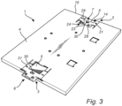
Fig. 3 , to which reference now is made, adevice 1 of the type described above with reference toFig. 1 is shown with afirst mounting bracket 3 inserted into afirst recess 5 of the device with an orientation in which themale connector end 6 extends beyond theperiphery 10 of thedevice 1, and with asecond mounting bracket 3 inserted into asecond recess 5 of thedevice 1 with an orientation in which thefemale connector end 7 is accessible from theperiphery 10 of thedevice 1. The mountingbrackets 3 are of the type described above with reference toFigs. 2a, 2b . InFig.3 , the device is depicted in a bottom view illustrating therear side 4 of thedevice 1. - In the shown embodiment, each mounting
bracket 3 is slidingly insertable into its associatedrecess 5 from a lateral side of thedevice 1 via theopening 14 in therecess 5 facing theperiphery 10 of thedevice 1. - Each mounting
bracket 3 is insertable into its associatedrecess 5 with a snap fit. In the shown embodiment, theprotrusions 22 provided on thebottom surface 21 of eachrecess 5 cooperate with the guidinggrooves openings 31 of the mountingbracket 3 for enabling said snap fit. When thefirst mounting bracket 3 is inserted, theprotrusions 22 of thefirst recess 5 will initially be received by the second guidinggrooves 32b of thefirst mounting bracket 3 and then guided towards theopenings 31 of thefirst mounting bracket 3 in response to insertion of thefirst mounting bracket 3 into thefirst recess 5. When theprotrusions 22 reach theopenings 31, they will snap into theopenings 31. Correspondingly, when thesecond mounting bracket 3 is inserted, theprotrusions 22 of thesecond recess 5 will initially be received by thefirst guiding grooves 32a of thesecond mounting bracket 3 and then guided towards the opening 31 of thesecond mounting bracket 3 in response to inserting thesecond mounting bracket 3 into thesecond recess 5. When theprotrusions 22 reach theopenings 31, they will snap into theopenings 31. - When each mounting
bracket 3 is inserted into its associatedrecess 5, the two opposinglateral flanges 19 of the mountingbracket 3 are received by the twogrooves 18 arranged at opposed lateral sides of therecess 5. Theflanges 19 are received by thegrooves 18 such that theabutment surface 13 of eachflange 19 faces thetop surface 20 of the associatedgroove 18. - As mentioned above, each
recess 5 comprises aprojection 23 arranged at theend 24 of therecess 5 and each mountingbracket 3 hasmale connector end 6 with adistal end 28 provided with anotch 29. As evident fromFig. 3 , thesecond mounting bracket 3 which is inserted into its associatedrecess 5 with the orientation in which thefemale connector end 7 is accessible from theperiphery 10 of thedevice 1, is inserted such that theprojection 23 of therecess 5 is received by thenotch 29 of thesecond mounting bracket 3. Hereby a guide is achieved ensuring correct insertion of thesecond mounting bracket 3. - As mentioned above, each mounting
bracket 3 may be provided with acentral dent 30 in the surface of the mountingbracket 3 configured to face away from thedevice 1 when the mountingbracket 3 is inserted into its associatedrecess 5. The mountingbrackets 3 illustrated inFig. 3 are each provided with such adent 30, which may be used for removing the mountingbrackets 3 from thedevice 1. More specifically, eachdent 30 enables removal of the mountingbracket 3 by means of a tool such as a screw driver by placing the tip of the tool inside thedent 30 for establishment of a grip enabling a manoeuvre for pushing the mountingbracket 3 out of therecess 5. - A method for attaching an
arrangement 100 to asurface 2 such as a wall is illustrated inFigs. 4a-c . Thearrangement 100 comprisesdevices 1 of the type described above with reference toFig. 1 and mountingbrackets 3 of the type described above with reference toFigs. 2a-b . In the figures, thearrangement 100 is depicted in a top view illustrating the firstmajor surfaces 15 corresponding to front sides of thedevices 1. - In
Fig. 4a , afirst device 1 of thearrangement 100 is provided. - The
first device 1 is provided withrecesses 5 forming a pair of oppositely arrangedrecesses 5 into which mountingbrackets 3 have been inserted with the orientation in which themale connector end 6 of each mountingbracket 3 extends beyond theperiphery 10 of thefirst device 1. - The
first device 1 is attached to thesurface 2 by means of attachment means 9 extending through the throughholes 8 of themale connector end 6 of each mountingbracket 3. In the shown embodiment, attachment means 9 in the form of schematically depicted screws are used. - Each
abutment surface 13 of the mountingbrackets 3 is configured to engage thedevice 1 in response to attaching thefirst device 1 to thesurface 2 by means of the attachment means 9 such that thefirst device 1 is pressed against thesurface 1. In the shown embodiment, eachabutment surface 13 is configured to be pressed against thetop surface 20 of eachgroove 18 when the attachment means 9 in the forms of screws are used, thereby pressing thefirst device 1 against thesurface 2. - In
Fig. 4b , thefirst device 1 is shown attached to thesurface 2 by the attachment means 9, and a second and athird device 1 are provided. - Each of the second and
third device 1 is provided withrecesses 5 forming a pair of oppositely arrangedrecesses 5 into which mountingbrackets 3 have been inserted, one mountingbracket 3 with the orientation in which themale connector end 6 extends beyond theperiphery 10 of therespective device 1 and one mounting bracket 3 (not visible) with the orientation in which thefemale connector end 7 is accessible from theperiphery 10 of therespective device 1. - The
second device 1 is arranged next to thefirst device 1 on the left side of thefirst device 1, and thethird device 1 is arranged next to thefirst device 1 on the right side of thefirst device 1. Subsequently, the second andthird devices 1 are moved towards thefirst device 1 such that the male connector ends 6 of the mountingbrackets 3 of thefirst device 1 are inserted into the female connector ends 7 of the adjoining mountingbrackets 3 of the neighbouring second andthird devices 1, which is shown inFig. 4c . - The
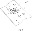
male connector end 6 the mountingbracket 3 being received by thefemale connector end 7 of an adjoining mountingbracket 3 is more clearly illustrated inFig. 5 , to which reference now also is made. - When the male connector ends 6 of the mounting
brackets 3 of thefirst device 1 are received by the respective female connector ends 7 of the adjoining mountingbrackets 3 of the neighbouring second andthird devices 1, the male connector engagement surfaces 11 of the mountingbrackets 3 of thefirst device 1 will engage the female engagement surfaces 12 of the mountingbrackets 3 of the second andthird device 1 such that movement of the neighbouring second andthird devices 1 are restricted. In the shown embodiment, the male connector engagement surfaces 11 and the female connector engagement surfaces 12 are chamfered such that the adjoining mountingbrackets 3 of the neighbouring second andthird devices 1 are pressed against thesurface 2. More specifically, the chamfered male connector and female connector engagement surfaces 11, 12 will cause the adjoining mountingbrackets 3 to be pressed against thesurface 2, which in turn will cause the abutment surfaces 13 of the adjoining mountingbrackets 3 to be pushed against thetop surfaces 20 of thegrooves 18 of therecesses 5 of the second andthird device 1, thereby causing them to be pressed against thesurface 2. - Subsequently, the second and
third device 1 may be secured to thesurface 2 by means of the attachment means 9, for instance in the form of screws. In the figure, thesecond device 1 to the left has not yet been secured by means of screws whereas thethird device 1 to the right has been secured to thesurface 2 by means of screws. - It is understood that the inventive arrangement may be used for attaching devices next to each other in the pattern of a row and/or column. In the embodiment shown in
Figs. 4a-c , thearrangement 100 is used for attachingdevices 1 next to each other in the pattern of a row. - In
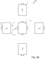
Figs. 6a-c , an embodiment of the invention is shown in which thedevices 1 of thearrangement 100 are attached to thesurface 2 next to each other in the pattern of a row and a column. In this embodiment, at least onedevice 1 is provided with two pairs ofopposed recesses 5, i.e. fourrecesses 5. A mountingbracket 3 is inserted into each of theserecesses 5 with the orientation in which themale connector end 6 extends beyond theperiphery 10 of thefirst device 1 and then attached to thesurface 2, as shown in Fig 7a. A second, third, fourth andfifth device 1 are subsequently arranged next to the first 1 device on all sides, connected to the mountingbrackets 3 of the first device and attached to the surface in analogy with what has been described above with reference toFigs. 4a-c . This is shown inFigs. 6b and6c . - It will be appreciated that the present invention is not limited to the embodiments shown. Several modifications and variations are thus conceivable within the scope of the invention which thus is exclusively defined by the appended claims.
Claims (13)
- An arrangement for attachment of devices (1) to a surface (2), such as a wall, the arrangement comprisingat least one device (1), andfor each device (1), at least two mounting brackets (3),wherein each device (1) has a rear side (4) provided with a recess (5) for each mounting bracket (3) associated to the device (1),wherein each mounting bracket (3) has a male connector end (6) and a female connector end (7), the male connector end (6) being configured to be received by the female connector (7) end of an adjoining mounting bracket (3) associated to a neighbouring device (1),wherein each male connector end (6) is provided with at least one through hole (8) for receiving an attachment means (9), such as a screw,wherein each mounting bracket (3) is insertable into its associated recess (5) with an orientation in which the male connector end (6) extends beyond a periphery (10) of the device (1), andwherein each mounting bracket (3) is insertable into its associated recess (3) with an orientation in which the female connector end (7) is accessible from the periphery (10) of the device (1).
- The arrangement according to claim 1, in which the male connector end (6) of each mounting bracket (3) is provided with a male connector engagement surface (11) and the female connector end (7) of each mounting bracket (3) is provided with a female connector engagement surface (12), wherein the male connector engagement surface (11) of the male connector end (6) of each mounting bracket (3) is configured to engage the female connector engagement surface (12) of the female connector end (7) of an adjoining mounting bracket (3) associated to a neighbouring device (1) such that movement of the neighbouring device (1) is restricted when the male connector end (6) is received by the female connector end (7) of the adjoining mounting bracket (3).
- The arrangement according to claim 2, wherein the female connector engagement surface (12) and the male connector engagement surface (11) are chamfered.
- The arrangement according to any one of claims 1-3, wherein each mounting bracket (3) is insertable into its associated recess (5) with a snap fit.
- The arrangement according to any one of the preceding claims, wherein each mounting bracket (3) is provided with at least one abutment surface (13) configured to engage its associated device (1) in response to attaching the device (1) to the surface (2) by means of the attachment means (9), such as a screw, extending through the at least one through hole (8) of the male connector end (6) of the mounting bracket (3) such that the device (1) is pressed against the surface (1) or in response to the male end connector (6) of an adjoining mounting bracket (3) of a neighbouring device (1) being received by the female connector end (7) of the mounting bracket (3) such that the device (1) is pressed against the surface.
- The arrangement according to any one of the preceding claims, wherein each recess (5) of each device (1) has an opening (14) facing the periphery (10) of the device (1) such that the mounting bracket (3) associated to the recess (5) is slidingly insertable into the recess (5) from a lateral side of the device (1).
- The arrangement according to any one of the preceding claims, wherein the recesses (5) of each device (1) form at least one pair of oppositely arranged recesses (5).
- The arrangement according to any one of the preceding claims, wherein each device (1) is rectangular in shape and has a first major surface (15); an opposing second major surface (16) forming said rear side (4) of the device; and four side edges (17a, 17b, 17c, 17d) forming said periphery (10) of the device (1) and extending between the first and second major surface (15, 16).
- The arrangement according to claim 8, wherein the recesses (5) provided in the rear surface (4) of each device (1) comprise a first recess (5) arranged in a rear surface portion (18a) adjoining a first side edge (17a) of said four side edges (17a, 17b, 17c, 17d) of the device (1); and a second recess (5) arranged in a rear surface portion (18b) adjoining a second side edge (17b) of said four side edges (17a, 17b, 17c, 17d) of the device (1), said second side edge (17b) being opposite to the first side edge (17a).
- The arrangement according to claim 9, wherein the recesses (5) provided in the rear surface (4) of each device (1) further comprise a third recess (5) arranged in a rear surface portion (18c) adjoining a third side edge (17c) of said four side edges (17a, 17b, 17c, 17d) of the device (1); and a fourth recess (5) arranged in a rear surface portion adjoining a fourth side edge (17d) of said four side edges (17a, 17b, 17c, 17d) of the device (1), said third side edge (17c) being opposite to the fourth side edge (17d).
- The arrangement according to any one of the preceding claims, wherein the at least one device (1) comprises a device in the form of an electronic unit.
- A method for attaching an arrangement (100) to a surface (2), such as a wall, the method comprising:providing an arrangement (100) according to any one of claims 1-11,inserting mounting brackets (3) into the associated recesses (5) of a first device (1) of said at least one device (1) with the orientation in which the male connector end (6) of each mounting bracket (3) extends beyond the periphery (10) of the first device (1), andattaching the first device (1) to the surface (2) by means of an attachment means (9), such as a screw, extending through the at least one through hole (8) of the male connector end (6) of each mounting bracket (3).
- The method according to claim 12, further comprisinginserting mounting brackets (3) into the associated recesses (5) of a second device (1) of said at least one device (1), wherein a first of the mounting brackets (3) is inserted into its associated recess (5) with the orientation in which the female connector end (7) is accessible from the periphery (10) of the second device (1) and wherein a second of the mounting brackets (3) is inserted into its associated recess (5) with the orientation in which the male connector end (6) extends beyond the periphery (10) of the second device (1),arranging the second device (1) next to the first device (1) such that the male connector end (6) of one of the mounting brackets (3) of the first device (1) is received by the female connector end (7) of the first of the mounting brackets (3) of the second device (1), andattaching the second device (1) to the surface (2) by means of an attachment means (9), such as a screw, extending through the at least one through hole (8) of the male connector end (6) of the second of the mounting brackets (3) of the second device (1).
Priority Applications (6)
| Application Number | Priority Date | Filing Date | Title |
|---|---|---|---|
| EP23171100.3A EP4459170B1 (en) | 2023-05-02 | 2023-05-02 | Arrangement for attachment of devices to a surface and method for attaching an arrangement to a surface |
| KR1020240028304A KR102898392B1 (en) | 2023-05-02 | 2024-02-27 | Arrangement for attachment of devices to a surface and method for attaching an arrangement to a surface |
| TW113107690A TWI932952B (en) | 2023-05-02 | 2024-03-04 | Arrangement for attachment of devices to a surface and method for attaching an arrangement to a surface |
| JP2024037333A JP7792982B2 (en) | 2023-05-02 | 2024-03-11 | Arrangement for mounting a device on a surface and method for mounting an arrangement on a surface - Patent Application 20070122997 |
| CN202410453517.XA CN118896233B (en) | 2023-05-02 | 2024-04-16 | Device for attaching a device to a surface and method for attaching a device to a surface |
| US18/645,937 US12674543B2 (en) | 2023-05-02 | 2024-04-25 | Arrangement for attachment of devices to a surface and method for attaching an arrangement to a surface |
Applications Claiming Priority (1)
| Application Number | Priority Date | Filing Date | Title |
|---|---|---|---|
| EP23171100.3A EP4459170B1 (en) | 2023-05-02 | 2023-05-02 | Arrangement for attachment of devices to a surface and method for attaching an arrangement to a surface |
Publications (3)
| Publication Number | Publication Date |
|---|---|
| EP4459170A1 true EP4459170A1 (en) | 2024-11-06 |
| EP4459170C0 EP4459170C0 (en) | 2025-10-22 |
| EP4459170B1 EP4459170B1 (en) | 2025-10-22 |
Family
ID=86328536
Family Applications (1)
| Application Number | Title | Priority Date | Filing Date |
|---|---|---|---|
| EP23171100.3A Active EP4459170B1 (en) | 2023-05-02 | 2023-05-02 | Arrangement for attachment of devices to a surface and method for attaching an arrangement to a surface |
Country Status (5)
| Country | Link |
|---|---|
| US (1) | US12674543B2 (en) |
| EP (1) | EP4459170B1 (en) |
| JP (1) | JP7792982B2 (en) |
| KR (1) | KR102898392B1 (en) |
| CN (1) | CN118896233B (en) |
Citations (3)
| Publication number | Priority date | Publication date | Assignee | Title |
|---|---|---|---|---|
| CA2585947A1 (en) | 2007-04-24 | 2008-10-24 | Xantrex International | Apparatus, method, and system for supporting an object |
| US20170220310A1 (en) * | 2015-09-25 | 2017-08-03 | Revolution Display, Llc | Devices For Creating Mosaicked Display Systems, and Display Mosaic Systems Comprising Same |
| DE202019106941U1 (en) * | 2019-11-20 | 2020-02-07 | Lingtong Exhibition System Co., Ltd. | Presentation frame with an LED display device |
Family Cites Families (18)
| Publication number | Priority date | Publication date | Assignee | Title |
|---|---|---|---|---|
| US2521134A (en) * | 1945-07-17 | 1950-09-05 | Mullins Mfg Corp | Wall cabinet hanger bar |
| JPS447317Y1 (en) * | 1965-06-14 | 1969-03-19 | ||
| JPS5342271Y2 (en) * | 1972-11-14 | 1978-10-12 | ||
| GB1484065A (en) * | 1974-10-21 | 1977-08-24 | Steelcase Inc | Apparatus for connecting articles and panels connected by such apparatus |
| US4571910A (en) * | 1983-08-01 | 1986-02-25 | Edward Cosentino | Apparatus for laying tile |
| JPH05145611A (en) * | 1991-08-30 | 1993-06-11 | Fujitsu Ltd | Connection structure of connection device for cordless telephone |
| JP2002034118A (en) * | 2000-07-18 | 2002-01-31 | Yazaki Corp | Bracket mounting structure for electrical junction box |
| US20030056413A1 (en) * | 2001-08-24 | 2003-03-27 | Wiemer James A. | Display system |
| US7572975B2 (en) * | 2006-11-28 | 2009-08-11 | Allied Moulded Products, Inc. | Electrical box with mounting system |
| US8167257B2 (en) * | 2007-04-24 | 2012-05-01 | Xantrex Technology Inc. | Apparatus, method, and system for supporting an object |
| CN204717296U (en) * | 2015-05-13 | 2015-10-21 | 中兴通讯股份有限公司 | Mounting apparatus |
| US9782023B2 (en) | 2015-09-11 | 2017-10-10 | Marc Fattahi | Wall hanging apparatus, system, and method |
| US9477438B1 (en) * | 2015-09-25 | 2016-10-25 | Revolution Display, Llc | Devices for creating mosaicked display systems, and display mosaic systems comprising same |
| US10492602B2 (en) | 2017-01-26 | 2019-12-03 | Bose Corporation | Electronics enclosure mounting |
| US11215319B2 (en) | 2020-05-27 | 2022-01-04 | Gantri, Inc. | Mounting bracket, mountable light, and methods of installation thereof |
| US20220015540A1 (en) | 2020-07-15 | 2022-01-20 | Suncraft Solutions, Inc. | Modular support assembly for vertically disposed objects including televisions and video monitors |
| CN111818248B (en) | 2020-07-17 | 2022-02-15 | Oppo广东移动通信有限公司 | Support structure, camera assembly and electronic equipment |
| CN215908830U (en) * | 2021-09-29 | 2022-02-25 | 上海创功通讯技术有限公司 | Wall-mounted structure and wall-mounted equipment |
-
2023
- 2023-05-02 EP EP23171100.3A patent/EP4459170B1/en active Active
-
2024
- 2024-02-27 KR KR1020240028304A patent/KR102898392B1/en active Active
- 2024-03-11 JP JP2024037333A patent/JP7792982B2/en active Active
- 2024-04-16 CN CN202410453517.XA patent/CN118896233B/en active Active
- 2024-04-25 US US18/645,937 patent/US12674543B2/en active Active
Patent Citations (3)
| Publication number | Priority date | Publication date | Assignee | Title |
|---|---|---|---|---|
| CA2585947A1 (en) | 2007-04-24 | 2008-10-24 | Xantrex International | Apparatus, method, and system for supporting an object |
| US20170220310A1 (en) * | 2015-09-25 | 2017-08-03 | Revolution Display, Llc | Devices For Creating Mosaicked Display Systems, and Display Mosaic Systems Comprising Same |
| DE202019106941U1 (en) * | 2019-11-20 | 2020-02-07 | Lingtong Exhibition System Co., Ltd. | Presentation frame with an LED display device |
Also Published As
| Publication number | Publication date |
|---|---|
| JP7792982B2 (en) | 2025-12-26 |
| TW202445056A (en) | 2024-11-16 |
| EP4459170C0 (en) | 2025-10-22 |
| KR20240160508A (en) | 2024-11-11 |
| KR102898392B1 (en) | 2025-12-09 |
| CN118896233A (en) | 2024-11-05 |
| US20240368881A1 (en) | 2024-11-07 |
| CN118896233B (en) | 2026-01-20 |
| US12674543B2 (en) | 2026-07-07 |
| JP2024170368A (en) | 2024-12-10 |
| EP4459170B1 (en) | 2025-10-22 |
Similar Documents
| Publication | Publication Date | Title |
|---|---|---|
| US6908326B2 (en) | Floating connector | |
| EP2012394B1 (en) | A connector and an assembling method therefor | |
| US8025538B2 (en) | Joint connector and wiring harness | |
| EP0658956B1 (en) | Low connector force electrical connector system | |
| EP3018763B1 (en) | Connector | |
| EP3146811B1 (en) | Printed circuit board arrangement | |
| US6435897B1 (en) | Compact PCI connector guide | |
| US5702257A (en) | Electrical connector and terminal therefor | |
| EP0696084A2 (en) | Connector with locking device | |
| WO2014085123A1 (en) | Power connector assembly having an alignment body | |
| EP2453530B1 (en) | Board connector, method of assembling it and method of mounting it to a board | |
| US20060154514A1 (en) | Slide-to-latch panel mount connector | |
| KR20190044007A (en) | Terminal assembly with a bus bar | |
| EP4459170B1 (en) | Arrangement for attachment of devices to a surface and method for attaching an arrangement to a surface | |
| CA1091318A (en) | Elongate electrical connector retaining device | |
| US4089581A (en) | Printed circuit board connector | |
| US20080139010A1 (en) | Blocking device for preventing board connector mismating | |
| US6205033B1 (en) | Electronic assembly circuit board guide apparatus | |
| EP1379115B1 (en) | Front rail of a rack | |
| US8123532B2 (en) | Carrier system for an electrical connector assembly | |
| US7172472B2 (en) | Joint connector, a joint terminal, and a production method for joint terminal | |
| EP2095469B1 (en) | Assembly device for receiving electronic modules | |
| EP1768217B1 (en) | A connector and connector assembly | |
| US6667887B2 (en) | Method and apparatus for locating and securing a component in a computer system | |
| CN215254201U (en) | Fast-assembling shingle nail |
Legal Events
| Date | Code | Title | Description |
|---|---|---|---|
| PUAI | Public reference made under article 153(3) epc to a published international application that has entered the european phase |
Free format text: ORIGINAL CODE: 0009012 |
|
| STAA | Information on the status of an ep patent application or granted ep patent |
Free format text: STATUS: REQUEST FOR EXAMINATION WAS MADE |
|
| 17P | Request for examination filed |
Effective date: 20231025 |
|
| AK | Designated contracting states |
Kind code of ref document: A1 Designated state(s): AL AT BE BG CH CY CZ DE DK EE ES FI FR GB GR HR HU IE IS IT LI LT LU LV MC ME MK MT NL NO PL PT RO RS SE SI SK SM TR |
|
| RIC1 | Information provided on ipc code assigned before grant |
Ipc: H02G 3/10 20060101ALI20250314BHEP Ipc: H02B 1/40 20060101ALI20250314BHEP Ipc: F16M 11/22 20060101ALI20250314BHEP Ipc: F16M 13/02 20060101AFI20250314BHEP |
|
| GRAP | Despatch of communication of intention to grant a patent |
Free format text: ORIGINAL CODE: EPIDOSNIGR1 |
|
| STAA | Information on the status of an ep patent application or granted ep patent |
Free format text: STATUS: GRANT OF PATENT IS INTENDED |
|
| INTG | Intention to grant announced |
Effective date: 20250723 |
|
| GRAS | Grant fee paid |
Free format text: ORIGINAL CODE: EPIDOSNIGR3 |
|
| GRAA | (expected) grant |
Free format text: ORIGINAL CODE: 0009210 |
|
| STAA | Information on the status of an ep patent application or granted ep patent |
Free format text: STATUS: THE PATENT HAS BEEN GRANTED |
|
| AK | Designated contracting states |
Kind code of ref document: B1 Designated state(s): AL AT BE BG CH CY CZ DE DK EE ES FI FR GB GR HR HU IE IS IT LI LT LU LV MC ME MK MT NL NO PL PT RO RS SE SI SK SM TR |
|
| REG | Reference to a national code |
Ref country code: CH Ref legal event code: F10 Free format text: ST27 STATUS EVENT CODE: U-0-0-F10-F00 (AS PROVIDED BY THE NATIONAL OFFICE) Effective date: 20251022 Ref country code: GB Ref legal event code: FG4D |
|
| REG | Reference to a national code |
Ref country code: DE Ref legal event code: R096 Ref document number: 602023007677 Country of ref document: DE |
|
| REG | Reference to a national code |
Ref country code: IE Ref legal event code: FG4D |
|
| U01 | Request for unitary effect filed |
Effective date: 20251022 |
|
| U07 | Unitary effect registered |
Designated state(s): AT BE BG DE DK EE FI FR IT LT LU LV MT NL PT RO SE SI Effective date: 20251029 |
|
| PG25 | Lapsed in a contracting state [announced via postgrant information from national office to epo] |
Ref country code: ES Free format text: LAPSE BECAUSE OF FAILURE TO SUBMIT A TRANSLATION OF THE DESCRIPTION OR TO PAY THE FEE WITHIN THE PRESCRIBED TIME-LIMIT Effective date: 20251022 |
|
| PG25 | Lapsed in a contracting state [announced via postgrant information from national office to epo] |
Ref country code: NO Free format text: LAPSE BECAUSE OF FAILURE TO SUBMIT A TRANSLATION OF THE DESCRIPTION OR TO PAY THE FEE WITHIN THE PRESCRIBED TIME-LIMIT Effective date: 20260122 |
|
| PG25 | Lapsed in a contracting state [announced via postgrant information from national office to epo] |
Ref country code: HR Free format text: LAPSE BECAUSE OF FAILURE TO SUBMIT A TRANSLATION OF THE DESCRIPTION OR TO PAY THE FEE WITHIN THE PRESCRIBED TIME-LIMIT Effective date: 20251022 |
|
| PG25 | Lapsed in a contracting state [announced via postgrant information from national office to epo] |
Ref country code: RS Free format text: LAPSE BECAUSE OF FAILURE TO SUBMIT A TRANSLATION OF THE DESCRIPTION OR TO PAY THE FEE WITHIN THE PRESCRIBED TIME-LIMIT Effective date: 20260122 |
|
| PG25 | Lapsed in a contracting state [announced via postgrant information from national office to epo] |
Ref country code: IS Free format text: LAPSE BECAUSE OF FAILURE TO SUBMIT A TRANSLATION OF THE DESCRIPTION OR TO PAY THE FEE WITHIN THE PRESCRIBED TIME-LIMIT Effective date: 20260222 |
|
| PG25 | Lapsed in a contracting state [announced via postgrant information from national office to epo] |
Ref country code: PL Free format text: LAPSE BECAUSE OF FAILURE TO SUBMIT A TRANSLATION OF THE DESCRIPTION OR TO PAY THE FEE WITHIN THE PRESCRIBED TIME-LIMIT Effective date: 20251022 |
|
| U20 | Renewal fee for the european patent with unitary effect paid |
Year of fee payment: 4 Effective date: 20260421 |
|
| PG25 | Lapsed in a contracting state [announced via postgrant information from national office to epo] |
Ref country code: SM Free format text: LAPSE BECAUSE OF FAILURE TO SUBMIT A TRANSLATION OF THE DESCRIPTION OR TO PAY THE FEE WITHIN THE PRESCRIBED TIME-LIMIT Effective date: 20251022 |
|
| PG25 | Lapsed in a contracting state [announced via postgrant information from national office to epo] |
Ref country code: CZ Free format text: LAPSE BECAUSE OF FAILURE TO SUBMIT A TRANSLATION OF THE DESCRIPTION OR TO PAY THE FEE WITHIN THE PRESCRIBED TIME-LIMIT Effective date: 20251022 |
|
| PG25 | Lapsed in a contracting state [announced via postgrant information from national office to epo] |
Ref country code: SK Free format text: LAPSE BECAUSE OF FAILURE TO SUBMIT A TRANSLATION OF THE DESCRIPTION OR TO PAY THE FEE WITHIN THE PRESCRIBED TIME-LIMIT Effective date: 20251022 |