EP0696084A2 - Connector with locking device - Google Patents
Connector with locking device Download PDFInfo
- Publication number
- EP0696084A2 EP0696084A2 EP95111277A EP95111277A EP0696084A2 EP 0696084 A2 EP0696084 A2 EP 0696084A2 EP 95111277 A EP95111277 A EP 95111277A EP 95111277 A EP95111277 A EP 95111277A EP 0696084 A2 EP0696084 A2 EP 0696084A2
- Authority
- EP
- European Patent Office
- Prior art keywords
- retainer
- locking
- housing
- projections
- retainers
- Prior art date
- Legal status (The legal status is an assumption and is not a legal conclusion. Google has not performed a legal analysis and makes no representation as to the accuracy of the status listed.)
- Granted
Links
- 238000003780 insertion Methods 0.000 claims abstract description 7
- 230000037431 insertion Effects 0.000 claims abstract description 7
- 230000000717 retained effect Effects 0.000 claims abstract description 4
- 238000000034 method Methods 0.000 description 2
- 238000012986 modification Methods 0.000 description 2
- 230000004048 modification Effects 0.000 description 2
- 238000004891 communication Methods 0.000 description 1
- 230000000694 effects Effects 0.000 description 1
- 230000005489 elastic deformation Effects 0.000 description 1
- 238000005192 partition Methods 0.000 description 1
- 229920003002 synthetic resin Polymers 0.000 description 1
- 239000000057 synthetic resin Substances 0.000 description 1
Images


Classifications
-
- H—ELECTRICITY
- H01—ELECTRIC ELEMENTS
- H01R—ELECTRICALLY-CONDUCTIVE CONNECTIONS; STRUCTURAL ASSOCIATIONS OF A PLURALITY OF MUTUALLY-INSULATED ELECTRICAL CONNECTING ELEMENTS; COUPLING DEVICES; CURRENT COLLECTORS
- H01R13/00—Details of coupling devices of the kinds covered by groups H01R12/70 or H01R24/00 - H01R33/00
- H01R13/40—Securing contact members in or to a base or case; Insulating of contact members
- H01R13/42—Securing in a demountable manner
- H01R13/436—Securing a plurality of contact members by one locking piece or operation
- H01R13/4361—Insertion of locking piece perpendicular to direction of contact insertion
- H01R13/4362—Insertion of locking piece perpendicular to direction of contact insertion comprising a temporary and a final locking position
Definitions
- the present invention relates to a connector provided with a retainer and, particularly to a connector having a retainer which is engageable with two types of projections to shift between a first locking position and a second locking position.
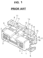
- a connector provided with a retainer (see FIG. 1).
- a multitude of cavities 3 extending in the lateral direction and opening in the opposite front and rear walls are formed in a housing 1 of the connector.
- a plurality of openings 10 in communication with these cavities 3 are formed in their upper and lower surfaces.
- Retainers 8 are disposed above and below the housing 1 and are connected therewith via hinge members 11.
- the retainers 8 are movable closer to and away from the housing 1.
- the retainers 8 are externally mountable on the housing 1 and are each formed at the opposite sides with a pair of side members 12 which are so deformable as to widen a spacing between the members.
- Each side member 12 is formed with a window 13.
- recesses 15 engageable with the corresponding side members 12 are formed at the opposite side surfaces of the housing 1.
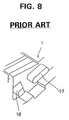
- two types of projections a first locking projection 17 and a second locking projection 18
- first locking projection 17 and second locking projection 18 are formed in each recess 15.
- the invention was developed in view of the above problem, and an object thereof is to provide a connector provided with a retainer which is not disengageable from a housing of the connector while it is moved from a first locking position to a second locking position.
- the engaging portions formed in the wing members are engaged with the first locking projections when the retainer is in its first locking position. At this stage, the insertion and withdrawal of the terminal fittings into and from are permitted.
- the wing members are deformed to widen the spacing therebetween so that the engaging portions are engaged with the second locking projections as well.
- the wing members since the height of at least one of the second locking projections is lower than that of the first locking projections, at least the corresponding engaging portion is still partially engaged with the respective first locking projection until the at least one second locking projection is engaged by the engaging portion.
- the retainer can shift to its second locking position without being disengaged from the housing, since the retainer is constantly engaged with the housing while being shifted from its first locking position to its second locking position.
- the disengagement of the retainer from the housing can be securely prevented.
- FIG. 1 As regards the prior art features of the embodiment.
- a housing 1 of a connector is unitarily formed of synthetic resin.
- the illustrated housing 1 is a female connector housing and is formed at its front part with a fitting portion 2 fittable with an unillustrated male connector housing.
- the housing 1 is formed with a multitude of cavities 3 for accommodating terminal fittings 5, the cavities 3 extending in a forward/backward direction and opening in the opposite front and rear walls.
- the respective cavities 3 are separated by partition walls 4.
- An engaging member or lance 6 engageable with the inserted terminal fitting 5 is deflectably formed in each cavity 3.
- the leading end of each engaging member 6 is partially cut away to form an engaging portion 7 so that the engaging member 6 engages the corresponding terminal fitting 5.
- the terminal fittings 5 are female terminal fittings and are each formed at its leading end with a hollow connecting portion 5a into which the leading end of an unillustrated corresponding male terminal fitting 5 is inserted.
- An engaging hole 5b formed at the lower surface of the connecting portion 5a engages the engaging member 6.
- a jaw portion 5c engageable with a corresponding locking portion 9 of a retainer 8 is formed at the upper surface of the connecting portion 5a.
- a plurality of slits 10 extend in parallel relationship over a specified distance backward from the fitting portion 2.
- the slits 10 are as many as the cavities 3, and communicate with the respective cavities 3.
- the slits 10 permit the respective locking portion 9 formed on the bottom surface of the retainer 8 to enter the cavities 3 when the retainer 8 is in its second locking position as described later, thereby enabling the engagement of the locking portions 9 with the terminal fittings 5.
- the retainers 8 are located above and below the housing 1 and are coupled therewith via elastically deformable hinge members 11. Both of the retainers 8 are unitarily formed with the housing 1 vertically symmetrically. On the surfaces of the retainers 8 facing the upper and lower surfaces of the housing 1, there are formed the locking portions 9 projectable into the cavities 3 through the openings 10. The locking portions 9 are arranged at the same pitch as the cavities 3 along the longitudinal direction of the retainers 8. The locking portions 9 are in the form of projections tapered toward their leading ends which project into the respective cavities 3. The locking portions 9 do not project into the cavities 3 when the retainers 8 are in their first locking positions, thereby permitting the insertion and withdrawal of the terminal fittings 5.
- the locking portions 9 deeply project into the cavities 3 and engage with the jaw portions 5c of the corresponding terminal fittings 5 as shown in FIG. 5.
- the terminal fittings 5 are doubly locked by the engagements with the engaging members 6 and with the locking portions 9 of the retainers 8, and thus can be securely retained in the cavities 3.
- a pair of side members 12 are formed at the opposite sides of each retainer 8, and the spacing between the pair of side members 12 is set such that they can engage recesses 15 in the side walls of the housing 1. Further, each pair of side members 12 are permitted to undergo an elastic deformation in such directions as to widen the spacing therebetween, and a window 13 in the form of an oblong hole is formed in each of the side members 12. Furthermore, a pair of projections 14 are formed on the surface of each retainer 8 facing the fitting portion 2. The projections 14 engage recesses (not shown) formed at the housing 1 when the retainers 8 are in their second locking positions, thereby preventing an undesired lifting of the retainers 8.
- the retainers 8 are mounted on the housing 1 in a partially (first) locking state (where the retainers 8 do not hinder the insertion and withdrawal of the terminal fittings 5 into and from the cavities 3) and in a fully (second) locking state. Therefore, on the opposite side surfaces of the housing 1, there are formed the recesses 15 in positions where the side members 12 are fitted.
- the bottom surface (in a vertical direction) of each recess 15 is a slanted surface having a specified downward inclination, and acts as a guide surface 16 for guiding the shifting of the corresponding retainer 8.
- projections 17 and 18 project in a horizontal direction for holding the retainer 8 in its first and second locking positions and are formed in parallel with the inclination of the guide surface 16.
- the recesses 15 are arranged symmetrically so as to correspond to the vertically symmetrically disposed retainers 8.
- the projections 17 and 18 are so formed as to have the same width (dimension W shown in FIG. 2), which is substantially equal to a width of the window 13. Further, a distance defined by the outer ends of the projections 17 and 18 is substantially equal to the entire length of the window 13. Accordingly, the window 13 is engageable only with the projection 17 as shown in FIG. 2 (first locking position) and is also stably engageable with both of the projections 17 and 18 as shown in FIG. 3 (second locking position).
- the parts of the projections 17 and 18, i.e., the both ends of the projection 17 and a lower end of the projection 18 in FIGS. 2 and 3 are formed to have an arcuate shape.
- a height (H2) (in the projection direction) of the projection 18 is slightly smaller than a thickness of the side member 12, and is lower than a height of the projection 17 (H1 > H2).
- This engagement margin is set such that the disengagement of the retainer 8 can be effectively prevented.
- the surface of the projection 18 facing the projection 17 is a slanted surface 18a for enabling the retainer 8 to smoothly move on the projection 18.
- the retainers 8 are held in positions away from the housing 1 as shown in FIG. 1.
- the retainers 8 are brought to their first locking positions prior to the insertion of the terminal fittings 5. More specifically, the hinge members 11 are bent to bring the retainers 8 closer to the housing 1, and the side members 12 are engaged with the recesses 15 to fit the projections 17 in the windows 13 (state shown in FIG. 7(a)). As a result, the retainers 8 are held in their first locking positions. Since the respective locking portions 9 do not enter the cavities 3 at this stage, the terminal fittings 5 can be smoothly inserted into the cavities 3.
- the inserted terminal fittings 5 cause the respective engaging members 6 to move (deflect) in a direction out of the cavities 3, but the engaging members 6 return to their original shape thereafter because of their elasticity, with the result that the engaging portions 7 of the engaging members 6 engage the engaging holes 5b, thereby partially locking the terminal fittings 5.
- the retainers 8 are moved further closer to the housing 1 to fit both of the projections 17 and 18 in the windows 13. As a result, the retainers 8 are fixed in their second locking positions. Since the respective locking portions 9 of the retainers 8 project into the cavities 3 and engage the jaw portions 5c of the corresponding terminal fittings 5 in this state, the terminal fittings 5 are retained in such a manner that they cannot come out of the cavities 3.
- the side members 12 While the retainers 8 shift from their first locking positions to their second locking positions, the side members 12 are displaced while being guided by the guide surfaces 16 of the recesses 15 and move on the projections 18 while undergoing a deformation to widen the spacing between them. During this period, since the windows 13 are still engaged with the projections 17 by the specified engagement margin, the undesired disengagement of the retainers 8 during the shift to their second locking positions can be avoided. When the windows 13 pass over the projections 18, the side members 12 return to their original shape because of their elasticity. As a result, the windows 13 are engaged with both of the projections 17 and 18 and thus the retainers 8 can be securely held in their second locking positions.
- the retainers 8 are not inadvertently disengaged from the housing 1 while shifting from their first locking positions to their second locking positions, thereby advantageously enabling a smooth sliding movement of the retainers 8.
Landscapes
- Connector Housings Or Holding Contact Members (AREA)
- Details Of Connecting Devices For Male And Female Coupling (AREA)
Abstract
Description
- The present invention relates to a connector provided with a retainer and, particularly to a connector having a retainer which is engageable with two types of projections to shift between a first locking position and a second locking position.
- In order to securely prevent terminal fittings inserted into the connector from coming out, there has been developed a connector provided with a retainer (see FIG. 1). Here, a brief description is given to this connector. A multitude of
cavities 3 extending in the lateral direction and opening in the opposite front and rear walls are formed in a housing 1 of the connector. A plurality ofopenings 10 in communication with thesecavities 3 are formed in their upper and lower surfaces.Retainers 8 are disposed above and below the housing 1 and are connected therewith viahinge members 11. Theretainers 8 are movable closer to and away from the housing 1. Theretainers 8 are externally mountable on the housing 1 and are each formed at the opposite sides with a pair ofside members 12 which are so deformable as to widen a spacing between the members. Eachside member 12 is formed with awindow 13. On the other hand,recesses 15 engageable with thecorresponding side members 12 are formed at the opposite side surfaces of the housing 1. As shown in detail in FIG. 8, two types of projections (afirst locking projection 17 and a second locking projection 18) are formed in eachrecess 15. When thewindows 13 of theretainer 8 are engaged with theprojections 17, locking portions of theretainers 8 enter theopenings 10, but do not enter thecavities 3. In this position, the insertion and withdrawal ofterminal fittings 5 are permitted (first locking position). When theretainers 8 are moved toward the housing 1 while widening the spacing between each pair of theside members 12 so that bothprojections windows 13, thelocking portions 9 deeply enter thecavities 3 and engage theterminal fittings 5, thereby preventing theterminal fittings 5 from coming out (second locking position). - As described above, when the
retainers 8 shift from the first locking position where only theprojections 17 are fitted in thewindows 13 to the second locking position where both of theprojections windows 13, the pairs of theside members 12 deform to widen the spacing between each pair. This shift of theretainers 8 is shown in detail in FIGS. 9(a) to 9(c). While thewindows 13 of theretainer 8 shift from the first locking position where they are engaged with the projections 17 (state shown in FIG. 9(a)) to the second locking position where they are engaged with theprojections windows 13 are temporarily engaged neither with theprojections 17 nor with theprojections 18 as shown in FIG. 9(b). Accordingly, unless theretainers 8 are moved along proper directions, they may be disengaged from the housing 1, resulting in a cumbersome operation of mounting theretainers 8 on the housing 1 again. - The invention was developed in view of the above problem, and an object thereof is to provide a connector provided with a retainer which is not disengageable from a housing of the connector while it is moved from a first locking position to a second locking position.
- The above object is accomplished by the invention defined in claim 1.
- The engaging portions formed in the wing members are engaged with the first locking projections when the retainer is in its first locking position. At this stage, the insertion and withdrawal of the terminal fittings into and from are permitted. In order to shift the retainer to its second locking position, the wing members are deformed to widen the spacing therebetween so that the engaging portions are engaged with the second locking projections as well. During the deformation of the wing members, since the height of at least one of the second locking projections is lower than that of the first locking projections, at least the corresponding engaging portion is still partially engaged with the respective first locking projection until the at least one second locking projection is engaged by the engaging portion. Thus, the retainer can shift to its second locking position without being disengaged from the housing, since the retainer is constantly engaged with the housing while being shifted from its first locking position to its second locking position. Thus, the disengagement of the retainer from the housing can be securely prevented.
- These and other objects, features and advantages of the present invention will become more apparent upon a reading of the following detailed description and accompanying drawings in which:
- FIG. 1 is a perspective view of a prior art connector,
- FIG. 2 is a partially enlarged side view of the connector when a retainer is in its first locking position,
- FIG. 3 is a partially enlarged side view of the connector when the retainer is in its second locking position,
- FIG. 4 is a side view in section of the connector when the retainer is in its first locking position,
- FIG. 5 is a side view in section of the connector when the retainer is in its second locking position,
- FIG. 6 is a perspective view showing first and second engagement projections,
- FIGS. 7(a) to 7(b) are sections showing a process of engagement of a side member with the projections,
- FIG. 8 is a perspective view of first and second engagement projections in a prior art connector, and
- FIGS. 9(a) to 9(c) are sections showing a process of engagement of a side member with the projections in the prior art connector.
- Hereafter, one embodiment of the invention is described in detail with respect to FIGS. 2 to 7. However, reference is made to FIG. 1 as regards the prior art features of the embodiment.
- A housing 1 of a connector is unitarily formed of synthetic resin. The illustrated housing 1 is a female connector housing and is formed at its front part with a
fitting portion 2 fittable with an unillustrated male connector housing. The housing 1 is formed with a multitude ofcavities 3 for accommodatingterminal fittings 5, thecavities 3 extending in a forward/backward direction and opening in the opposite front and rear walls. Therespective cavities 3 are separated bypartition walls 4. An engaging member or lance 6 engageable with the insertedterminal fitting 5 is deflectably formed in eachcavity 3. The leading end of eachengaging member 6 is partially cut away to form anengaging portion 7 so that theengaging member 6 engages thecorresponding terminal fitting 5. Theterminal fittings 5 are female terminal fittings and are each formed at its leading end with a hollow connectingportion 5a into which the leading end of an unillustrated correspondingmale terminal fitting 5 is inserted. Anengaging hole 5b formed at the lower surface of the connectingportion 5a engages theengaging member 6. Ajaw portion 5c engageable with acorresponding locking portion 9 of aretainer 8 is formed at the upper surface of the connectingportion 5a. - In each of the upper and lower surfaces of the housing 1, a plurality of
slits 10 extend in parallel relationship over a specified distance backward from thefitting portion 2. Theslits 10 are as many as thecavities 3, and communicate with therespective cavities 3. Theslits 10 permit therespective locking portion 9 formed on the bottom surface of theretainer 8 to enter thecavities 3 when theretainer 8 is in its second locking position as described later, thereby enabling the engagement of thelocking portions 9 with theterminal fittings 5. - The
retainers 8 are located above and below the housing 1 and are coupled therewith via elasticallydeformable hinge members 11. Both of theretainers 8 are unitarily formed with the housing 1 vertically symmetrically. On the surfaces of theretainers 8 facing the upper and lower surfaces of the housing 1, there are formed thelocking portions 9 projectable into thecavities 3 through theopenings 10. Thelocking portions 9 are arranged at the same pitch as thecavities 3 along the longitudinal direction of theretainers 8. Thelocking portions 9 are in the form of projections tapered toward their leading ends which project into therespective cavities 3. Thelocking portions 9 do not project into thecavities 3 when theretainers 8 are in their first locking positions, thereby permitting the insertion and withdrawal of theterminal fittings 5. When theretainers 8 are in their second locking positions, thelocking portions 9 deeply project into thecavities 3 and engage with thejaw portions 5c of the correspondingterminal fittings 5 as shown in FIG. 5. In this way, theterminal fittings 5 are doubly locked by the engagements with theengaging members 6 and with thelocking portions 9 of theretainers 8, and thus can be securely retained in thecavities 3. - A pair of
side members 12 are formed at the opposite sides of eachretainer 8, and the spacing between the pair ofside members 12 is set such that they can engagerecesses 15 in the side walls of the housing 1. Further, each pair ofside members 12 are permitted to undergo an elastic deformation in such directions as to widen the spacing therebetween, and awindow 13 in the form of an oblong hole is formed in each of theside members 12. Furthermore, a pair ofprojections 14 are formed on the surface of eachretainer 8 facing thefitting portion 2. Theprojections 14 engage recesses (not shown) formed at the housing 1 when theretainers 8 are in their second locking positions, thereby preventing an undesired lifting of theretainers 8. - The
retainers 8 are mounted on the housing 1 in a partially (first) locking state (where theretainers 8 do not hinder the insertion and withdrawal of theterminal fittings 5 into and from the cavities 3) and in a fully (second) locking state. Therefore, on the opposite side surfaces of the housing 1, there are formed therecesses 15 in positions where theside members 12 are fitted. The bottom surface (in a vertical direction) of eachrecess 15 is a slanted surface having a specified downward inclination, and acts as aguide surface 16 for guiding the shifting of thecorresponding retainer 8. In eachrecess 15,projections retainer 8 in its first and second locking positions and are formed in parallel with the inclination of theguide surface 16. Therecesses 15 are arranged symmetrically so as to correspond to the vertically symmetrically disposedretainers 8. - The
projections window 13. Further, a distance defined by the outer ends of theprojections window 13. Accordingly, thewindow 13 is engageable only with theprojection 17 as shown in FIG. 2 (first locking position) and is also stably engageable with both of theprojections window 13, the parts of theprojections projection 17 and a lower end of theprojection 18 in FIGS. 2 and 3, are formed to have an arcuate shape. Further, a height (H2) (in the projection direction) of theprojection 18 is slightly smaller than a thickness of theside member 12, and is lower than a height of the projection 17 (H1 > H2). Thus, even while theside member 12 moves over theprojection 18 so as to fit theprojection 18 in the window 13 (see FIG. 7(b)), thewindow 13 is engaged with theprojection 17 by a specified engagement margin. This engagement margin is set such that the disengagement of theretainer 8 can be effectively prevented. Furthermore, the surface of theprojection 18 facing theprojection 17 is aslanted surface 18a for enabling theretainer 8 to smoothly move on theprojection 18. - The action and effect of the thus constructed embodiment are specifically described. When the connector is formed, the
retainers 8 are held in positions away from the housing 1 as shown in FIG. 1. Theretainers 8 are brought to their first locking positions prior to the insertion of theterminal fittings 5. More specifically, thehinge members 11 are bent to bring theretainers 8 closer to the housing 1, and theside members 12 are engaged with therecesses 15 to fit theprojections 17 in the windows 13 (state shown in FIG. 7(a)). As a result, theretainers 8 are held in their first locking positions. Since therespective locking portions 9 do not enter thecavities 3 at this stage, theterminal fittings 5 can be smoothly inserted into thecavities 3. The insertedterminal fittings 5 cause the respective engagingmembers 6 to move (deflect) in a direction out of thecavities 3, but the engagingmembers 6 return to their original shape thereafter because of their elasticity, with the result that the engagingportions 7 of the engagingmembers 6 engage the engagingholes 5b, thereby partially locking theterminal fittings 5. - Subsequently, the
retainers 8 are moved further closer to the housing 1 to fit both of theprojections windows 13. As a result, theretainers 8 are fixed in their second locking positions. Since therespective locking portions 9 of theretainers 8 project into thecavities 3 and engage thejaw portions 5c of the correspondingterminal fittings 5 in this state, theterminal fittings 5 are retained in such a manner that they cannot come out of thecavities 3. - While the
retainers 8 shift from their first locking positions to their second locking positions, theside members 12 are displaced while being guided by the guide surfaces 16 of therecesses 15 and move on theprojections 18 while undergoing a deformation to widen the spacing between them. During this period, since thewindows 13 are still engaged with theprojections 17 by the specified engagement margin, the undesired disengagement of theretainers 8 during the shift to their second locking positions can be avoided. When thewindows 13 pass over theprojections 18, theside members 12 return to their original shape because of their elasticity. As a result, thewindows 13 are engaged with both of theprojections retainers 8 can be securely held in their second locking positions. - As described above, according to the foregoing embodiment, the
retainers 8 are not inadvertently disengaged from the housing 1 while shifting from their first locking positions to their second locking positions, thereby advantageously enabling a smooth sliding movement of theretainers 8. - Various changes and modifications may be made in the invention. The following modifications are also embraced by the technical scope of the invention.
- (1) Although the
projections window 13 in the foregoing embodiment,separate windows 13 may be formed for theprojections window 13 for theprojection 17 needs to be an oblong hole having a length for permitting the sliding movement of theretainer 8. - (2) The invention may be applied to male connectors. The number of contacts of the connector, the number of the
hinge members 11, etc. may be suitably changed. -
- 1
- Housing
- 3
- Cavity
- 5
- Terminal Fitting
- 8
- Retainer
- 9
- Locking Portion
- 12
- Side Member
- 13
- Window
- 17
- First Locking Projection
- 18
- Second Locking Projection
Claims (6)
- A connector, comprising:
a housing (1),
a retainer (8) having a pair of wing members (12) which are so deformable as to widen a spacing therebetween,
first and second locking projections (17,18) formed on each of the surfaces of the housing (1) facing the wing members (12), and
an engaging portion (13) formed in each wing member (12) for holding the retainer (8) in a first locking position in which the engaging portions (13) are engaged with the first locking projections (17) and in which the insertion and withdrawal of terminal fittings (5) into and from the housing (1) are permitted, and for holding the retainer (8) in a second locking position in which the engaging portions (13) are engaged with both of the first and second locking projections (17,18) and in which the terminal fittings (5) are securely retained in the housing (1), the wing members (13) of the retainer (8) undergoing a deformation when the retainer (8) is shifted between the first and second locking position,
wherein the height of at least one of the second locking projections (18) is lower than that of the first locking projections (17). - A connector according to claim 1, wherein the engaging portions are windows (13) formed in the wing members (12).
- A connector according to claim 2, where the width of the windows (13) corresponds to the width of the first and/or the second locking projections (17, 18), so that the projections act as guide members when shifting the retainer from the first to the second locking position.
- A connector according to any of claims 1 to 3, wherein the wing members are side members (12) provided at its opposite sides.
- A connector according to any of claims 1 to 4, wherein the retainer (8) is connected with the housing (1) by a connection member (11).
- A connector according to any of claims 1 to 5, wherein the height of each of the second locking projections (18) is lower than that of the first locking projections (17).
Applications Claiming Priority (3)
| Application Number | Priority Date | Filing Date | Title |
|---|---|---|---|
| JP202746/94 | 1994-08-03 | ||
| JP20274694 | 1994-08-03 | ||
| JP6202746A JP2964880B2 (en) | 1994-08-03 | 1994-08-03 | connector |
Publications (3)
| Publication Number | Publication Date |
|---|---|
| EP0696084A2 true EP0696084A2 (en) | 1996-02-07 |
| EP0696084A3 EP0696084A3 (en) | 1996-03-06 |
| EP0696084B1 EP0696084B1 (en) | 2000-09-27 |
Family
ID=16462481
Family Applications (1)
| Application Number | Title | Priority Date | Filing Date |
|---|---|---|---|
| EP95111277A Expired - Lifetime EP0696084B1 (en) | 1994-08-03 | 1995-07-18 | Connector with locking device |
Country Status (4)
| Country | Link |
|---|---|
| US (1) | US5651703A (en) |
| EP (1) | EP0696084B1 (en) |
| JP (1) | JP2964880B2 (en) |
| DE (1) | DE69518960T2 (en) |
Cited By (4)
| Publication number | Priority date | Publication date | Assignee | Title |
|---|---|---|---|---|
| WO1998052251A1 (en) * | 1997-05-15 | 1998-11-19 | The Whitaker Corporation | Electrical connector |
| EP1271705A1 (en) * | 2001-06-19 | 2003-01-02 | Sumitomo Wiring Systems, Ltd. | Connector with open-stopping means for retainer |
| EP1345288A1 (en) * | 2002-03-15 | 2003-09-17 | Sumitomo Wiring Systems, Ltd. | A connector and a method of assembling |
| EP1411593A1 (en) * | 2002-10-15 | 2004-04-21 | Sumitomo Wiring Systems, Ltd. | A connector |
Families Citing this family (22)
| Publication number | Priority date | Publication date | Assignee | Title |
|---|---|---|---|---|
| JP4140667B2 (en) * | 1996-08-01 | 2008-08-27 | 住友電装株式会社 | connector |
| JP3301329B2 (en) * | 1996-12-27 | 2002-07-15 | 住友電装株式会社 | connector |
| US5890935A (en) * | 1997-12-10 | 1999-04-06 | Molex Incorporated | Electrical connector with terminal position assurance device |
| JP3456165B2 (en) * | 1999-06-18 | 2003-10-14 | 住友電装株式会社 | connector |
| US6183313B1 (en) * | 1998-04-17 | 2001-02-06 | Yazaki Corporation | Double lock connector |
| JP3690788B2 (en) | 1999-12-27 | 2005-08-31 | 矢崎総業株式会社 | Connector with rear holder and manufacturing method thereof |
| JP3799542B2 (en) * | 2000-12-01 | 2006-07-19 | 住友電装株式会社 | connector |
| JP3765390B2 (en) * | 2000-12-28 | 2006-04-12 | 住友電装株式会社 | connector |
| JP4126179B2 (en) * | 2002-02-01 | 2008-07-30 | 住友電装株式会社 | connector |
| JP3896896B2 (en) * | 2002-05-23 | 2007-03-22 | 住友電装株式会社 | connector |
| JP3415137B1 (en) * | 2002-06-24 | 2003-06-09 | 住友電装株式会社 | connector |
| JP3984565B2 (en) * | 2003-06-11 | 2007-10-03 | 住友電装株式会社 | connector |
| JP4175254B2 (en) * | 2003-12-25 | 2008-11-05 | 住友電装株式会社 | connector |
| JP2005327617A (en) * | 2004-05-14 | 2005-11-24 | Sumitomo Wiring Syst Ltd | Connector |
| JP4656911B2 (en) * | 2004-10-20 | 2011-03-23 | 住友電装株式会社 | connector |
| JP4900026B2 (en) * | 2007-05-08 | 2012-03-21 | 住友電装株式会社 | connector |
| JP2013038044A (en) * | 2011-08-11 | 2013-02-21 | Sumitomo Wiring Syst Ltd | Connector |
| JP5376031B2 (en) * | 2012-10-23 | 2013-12-25 | 住友電装株式会社 | connector |
| JP5725237B1 (en) | 2014-05-19 | 2015-05-27 | 第一精工株式会社 | Electrical connector |
| FR3093596B1 (en) * | 2019-03-07 | 2022-04-22 | Aptiv Tech Ltd | Connector with two directions of movement of the device to ensure the position of the contacts |
| JP7539260B2 (en) * | 2020-06-08 | 2024-08-23 | モレックス エルエルシー | Connector, connector assembly, and retainer |
| DE102020117717B4 (en) * | 2020-07-06 | 2022-02-03 | Md Elektronik Gmbh | Electrical connector |
Family Cites Families (4)
| Publication number | Priority date | Publication date | Assignee | Title |
|---|---|---|---|---|
| JP2807245B2 (en) * | 1989-01-10 | 1998-10-08 | 日本エー・エム・ピー株式会社 | Electrical connector |
| JP2901110B2 (en) * | 1992-05-25 | 1999-06-07 | 矢崎総業株式会社 | Electrical connector with rear holder |
| JP2789973B2 (en) * | 1992-11-06 | 1998-08-27 | 住友電装株式会社 | connector |
| JP2581487Y2 (en) * | 1993-09-16 | 1998-09-21 | 住友電装株式会社 | connector |
-
1994
- 1994-08-03 JP JP6202746A patent/JP2964880B2/en not_active Expired - Lifetime
-
1995
- 1995-07-18 DE DE69518960T patent/DE69518960T2/en not_active Expired - Lifetime
- 1995-07-18 EP EP95111277A patent/EP0696084B1/en not_active Expired - Lifetime
- 1995-08-02 US US08/510,548 patent/US5651703A/en not_active Expired - Lifetime
Non-Patent Citations (1)
| Title |
|---|
| None |
Cited By (4)
| Publication number | Priority date | Publication date | Assignee | Title |
|---|---|---|---|---|
| WO1998052251A1 (en) * | 1997-05-15 | 1998-11-19 | The Whitaker Corporation | Electrical connector |
| EP1271705A1 (en) * | 2001-06-19 | 2003-01-02 | Sumitomo Wiring Systems, Ltd. | Connector with open-stopping means for retainer |
| EP1345288A1 (en) * | 2002-03-15 | 2003-09-17 | Sumitomo Wiring Systems, Ltd. | A connector and a method of assembling |
| EP1411593A1 (en) * | 2002-10-15 | 2004-04-21 | Sumitomo Wiring Systems, Ltd. | A connector |
Also Published As
| Publication number | Publication date |
|---|---|
| EP0696084A3 (en) | 1996-03-06 |
| DE69518960D1 (en) | 2000-11-02 |
| JP2964880B2 (en) | 1999-10-18 |
| DE69518960T2 (en) | 2001-04-26 |
| US5651703A (en) | 1997-07-29 |
| EP0696084B1 (en) | 2000-09-27 |
| JPH0845596A (en) | 1996-02-16 |
Similar Documents
| Publication | Publication Date | Title |
|---|---|---|
| EP0696084A2 (en) | Connector with locking device | |
| US6244880B1 (en) | Low-insertion force connector | |
| US6241542B1 (en) | Connector with shorting terminal | |
| EP1271705B1 (en) | Connector with open-stopping means for retainer | |
| US6497591B2 (en) | Connector | |
| US5803756A (en) | Electrical connector with short circuit terminal | |
| US20020193013A1 (en) | Connector | |
| EP0955696A1 (en) | Electrical connector with terminal position assurance device | |
| US6599154B2 (en) | Connector with obliquely Moveable retainer | |
| EP0905819B1 (en) | A connector provided with a retainer | |
| EP0623973B1 (en) | Connector | |
| EP0940883B1 (en) | Connector retaining construction | |
| US6935904B2 (en) | Connector | |
| US6851987B2 (en) | Connector | |
| EP1094559B1 (en) | Electrical connector having a terminal retainer | |
| US5468162A (en) | Locking connector | |
| EP1172895B1 (en) | Connector | |
| EP1156553B1 (en) | A connector housing and a connector | |
| US6695651B2 (en) | Connector | |
| EP1416592B1 (en) | A connector and method of connecting a connector with a mating connector | |
| US6811452B2 (en) | Connector with a retainer | |
| US6371818B1 (en) | Connector | |
| EP1150388B1 (en) | A shake preventing construction for a terminal fitting and connector | |
| US6488547B2 (en) | Connector with longitudinally spaced locks for retaining terminal fittings | |
| WO2007062683A1 (en) | Electrical connector with secondary locking means |
Legal Events
| Date | Code | Title | Description |
|---|---|---|---|
| PUAI | Public reference made under article 153(3) epc to a published international application that has entered the european phase |
Free format text: ORIGINAL CODE: 0009012 |
|
| PUAL | Search report despatched |
Free format text: ORIGINAL CODE: 0009013 |
|
| 17P | Request for examination filed |
Effective date: 19950718 |
|
| AK | Designated contracting states |
Kind code of ref document: A2 Designated state(s): DE GB |
|
| AK | Designated contracting states |
Kind code of ref document: A3 Designated state(s): DE GB |
|
| 17Q | First examination report despatched |
Effective date: 19990208 |
|
| RIC1 | Information provided on ipc code assigned before grant |
Free format text: 6H 01R 13/436 A, 6H 01R 13/42 B |
|
| RIC1 | Information provided on ipc code assigned before grant |
Free format text: 6H 01R 13/436 A, 6H 01R 13/42 B |
|
| GRAG | Despatch of communication of intention to grant |
Free format text: ORIGINAL CODE: EPIDOS AGRA |
|
| GRAG | Despatch of communication of intention to grant |
Free format text: ORIGINAL CODE: EPIDOS AGRA |
|
| GRAH | Despatch of communication of intention to grant a patent |
Free format text: ORIGINAL CODE: EPIDOS IGRA |
|
| GRAH | Despatch of communication of intention to grant a patent |
Free format text: ORIGINAL CODE: EPIDOS IGRA |
|
| GRAA | (expected) grant |
Free format text: ORIGINAL CODE: 0009210 |
|
| AK | Designated contracting states |
Kind code of ref document: B1 Designated state(s): DE GB |
|
| REF | Corresponds to: |
Ref document number: 69518960 Country of ref document: DE Date of ref document: 20001102 |
|
| EN | Fr: translation not filed | ||
| PLBE | No opposition filed within time limit |
Free format text: ORIGINAL CODE: 0009261 |
|
| STAA | Information on the status of an ep patent application or granted ep patent |
Free format text: STATUS: NO OPPOSITION FILED WITHIN TIME LIMIT |
|
| 26N | No opposition filed | ||
| REG | Reference to a national code |
Ref country code: GB Ref legal event code: IF02 |
|
| PGFP | Annual fee paid to national office [announced via postgrant information from national office to epo] |
Ref country code: GB Payment date: 20020717 Year of fee payment: 8 |
|
| PG25 | Lapsed in a contracting state [announced via postgrant information from national office to epo] |
Ref country code: GB Free format text: LAPSE BECAUSE OF NON-PAYMENT OF DUE FEES Effective date: 20030718 |
|
| GBPC | Gb: european patent ceased through non-payment of renewal fee |
Effective date: 20030718 |
|
| PGFP | Annual fee paid to national office [announced via postgrant information from national office to epo] |
Ref country code: DE Payment date: 20140716 Year of fee payment: 20 |
|
| REG | Reference to a national code |
Ref country code: DE Ref legal event code: R071 Ref document number: 69518960 Country of ref document: DE |