EP4459028A1 - Wäschebehandlungsvorrichtung - Google Patents
Wäschebehandlungsvorrichtung Download PDFInfo
- Publication number
- EP4459028A1 EP4459028A1 EP23914898.4A EP23914898A EP4459028A1 EP 4459028 A1 EP4459028 A1 EP 4459028A1 EP 23914898 A EP23914898 A EP 23914898A EP 4459028 A1 EP4459028 A1 EP 4459028A1
- Authority
- EP
- European Patent Office
- Prior art keywords
- control panel
- treating apparatus
- laundry treating
- cabinet cover
- hole
- Prior art date
- Legal status (The legal status is an assumption and is not a legal conclusion. Google has not performed a legal analysis and makes no representation as to the accuracy of the status listed.)
- Pending
Links
Images


Classifications
-
- D—TEXTILES; PAPER
- D06—TREATMENT OF TEXTILES OR THE LIKE; LAUNDERING; FLEXIBLE MATERIALS NOT OTHERWISE PROVIDED FOR
- D06F—LAUNDERING, DRYING, IRONING, PRESSING OR FOLDING TEXTILE ARTICLES
- D06F34/00—Details of control systems for washing machines, washer-dryers or laundry dryers
- D06F34/28—Arrangements for program selection, e.g. control panels therefor; Arrangements for indicating program parameters, e.g. the selected program or its progress
- D06F34/34—Arrangements for program selection, e.g. control panels therefor; Arrangements for indicating program parameters, e.g. the selected program or its progress characterised by mounting or attachment features, e.g. detachable control panels or detachable display panels
-
- D—TEXTILES; PAPER
- D06—TREATMENT OF TEXTILES OR THE LIKE; LAUNDERING; FLEXIBLE MATERIALS NOT OTHERWISE PROVIDED FOR
- D06F—LAUNDERING, DRYING, IRONING, PRESSING OR FOLDING TEXTILE ARTICLES
- D06F34/00—Details of control systems for washing machines, washer-dryers or laundry dryers
- D06F34/04—Signal transfer or data transmission arrangements
- D06F34/05—Signal transfer or data transmission arrangements for wireless communication between components, e.g. for remote monitoring or control
-
- D—TEXTILES; PAPER
- D06—TREATMENT OF TEXTILES OR THE LIKE; LAUNDERING; FLEXIBLE MATERIALS NOT OTHERWISE PROVIDED FOR
- D06F—LAUNDERING, DRYING, IRONING, PRESSING OR FOLDING TEXTILE ARTICLES
- D06F34/00—Details of control systems for washing machines, washer-dryers or laundry dryers
- D06F34/28—Arrangements for program selection, e.g. control panels therefor; Arrangements for indicating program parameters, e.g. the selected program or its progress
- D06F34/30—Arrangements for program selection, e.g. control panels therefor; Arrangements for indicating program parameters, e.g. the selected program or its progress characterised by mechanical features, e.g. buttons or rotary dials
-
- D—TEXTILES; PAPER
- D06—TREATMENT OF TEXTILES OR THE LIKE; LAUNDERING; FLEXIBLE MATERIALS NOT OTHERWISE PROVIDED FOR
- D06F—LAUNDERING, DRYING, IRONING, PRESSING OR FOLDING TEXTILE ARTICLES
- D06F34/00—Details of control systems for washing machines, washer-dryers or laundry dryers
- D06F34/28—Arrangements for program selection, e.g. control panels therefor; Arrangements for indicating program parameters, e.g. the selected program or its progress
- D06F34/32—Arrangements for program selection, e.g. control panels therefor; Arrangements for indicating program parameters, e.g. the selected program or its progress characterised by graphical features, e.g. touchscreens
-
- D—TEXTILES; PAPER
- D06—TREATMENT OF TEXTILES OR THE LIKE; LAUNDERING; FLEXIBLE MATERIALS NOT OTHERWISE PROVIDED FOR
- D06F—LAUNDERING, DRYING, IRONING, PRESSING OR FOLDING TEXTILE ARTICLES
- D06F2101/00—User input for the control of domestic laundry washing machines, washer-dryers or laundry dryers
- D06F2101/20—Operation modes, e.g. delicate laundry washing programs, service modes or refreshment cycles
Definitions
- the present disclosure relates to a laundry treating apparatus and, more specifically, to a laundry treating apparatus in which a control signal for a processing cycle can be input through a control panel.
- a laundry treating apparatus is an apparatus that processes laundry by applying physical and chemical actions to the laundry.
- the term "laundry treating apparatus” is used to collectively refer to a washing apparatus that removes contaminants from laundry, a spin-drying apparatus that spin-dries laundry by rotating a washing tub containing laundry at high speed, a drying apparatus that dries wet laundry by applying hot air into the washing tub, and the like.
- laundry treating apparatuses that have recently appeared do not just perform washing, drywashing, and drying functions individually in respective apparatuses, but are configured to perform all of the above-mentioned functions together in one laundry treating apparatus.
- a series of operations such as a washing course, a rinsing course, a spin-drying course, a drying course, and the like can be appropriately controlled through a user's manipulation or automatic control.
- a typical laundry treating apparatus includes a control panel configured to be capable of displaying visual information related to a processing operation to a user and capable of receiving user input. That is, the control panel is provided for a user interface (UI).
- UI user interface
- control panel may include input units or selection units, such as various buttons for user operation, and various display units to provide information to a user. All of these various input units, selection units, and display units may be referred to as user interfaces.
- a cabinet cover that defines the exterior of the laundry treating apparatus may be designed as an integrated sheet metal product to achieve a seamless structure.
- the control panel provided on the front surface of the laundry treating apparatus to facilitate user access and operation also needs to match the exterior design of the laundry treating apparatus, which is designed to have the seamless structure.
- Korean Patent No. 10-2257622 discloses a washing apparatus.
- a control panel provided on the front upper portion of a cabinet cover to face the front of the product
- an operation unit installed on the control panel to select a specific wash course and accompanying options by rotating a knob
- a display configured to selectively display the wash course and options based on the operation of the operation unit, and the like are disclosed.
- control panel since the structure of the control panel is relatively complex in that a rotary knob for user operation is applied, there is a problem in that a structure for coupling the control panel to a cabinet cover designed as an integrated sheet metal product also becomes complicated.
- Korean Patent Laid-open Publication No. 10-2013-0109356 discloses a washing machine.
- a cabinet a control panel disposed on the front surface of the cabinet, a display unit mounted on the control panel such that the front surface thereof is exposed in front of the control panel, and the like are disclosed.
- the display unit is provided in a touch screen type and performs both input and display functions.
- the display unit is not directly coupled to the cabinet, but has a complex structure in which the display unit is assembled to the cabinet in the state of being installed to a control panel assembly.
- control panel should be easily installed on the cabinet cover while also ensuring that the control panel also matches the exterior design of the cabinet cover.
- the present disclosure is to solve the above-mentioned problems of a laundry treating apparatus including a control panel.
- the present disclosure is to provide a laundry treating apparatus in which a parting line between a cabinet cover and a control panel is minimized, so that that the control panel can match the exterior design with a seamless structure.
- the present disclosure is to provide a laundry treating apparatus in which only the portions of a control panel that are essential to be exposed to a user are exposed outside, so that the control panel can match the exterior design with a seamless structure.
- the present disclosure is to provide a laundry treating apparatus in which the structure of the cabinet cover on which the control panel is installed is optimized so that the laundry treating apparatus can be manufactured more easily and efficiently.
- the laundry treating apparatus is configured such that no parting line is formed between a cabinet cover and a control panel on exterior.
- the control panel is installed inside the cabinet cover that forms the exterior so that the control panel is not separated from the cabinet cover on the exterior.
- the laundry treating apparatus is configured such that the portions of the control panel that are not directly necessary for user operation is not exposed outside.
- the control panel is installed inside the cabinet cover, and only a portion of the control panel is configured to be exposed outside through the first through hole provided in the cabinet cover.
- the laundry treating apparatus is configured such that the structure of the cabinet cover is suitable for installation of a control panel while improving manufacturing efficiency.
- the control panel is configured to be fastened to a hook protrusion protruding from a second through hole provided in the cabinet cover.
- a hook at the lower end portion of the control panel may be inserted into and fastened to a hook hole penetrating the hook protrusion in the longitudinal direction.
- the upper end portion of the control panel may be screwed to the inner surface of the cabinet cover.
- a pair of second through holes and control buttons may each be arranged symmetrically on opposite sides of the control panel.
- control panel may be fastened to both the respective hook protrusions which are provided at the pair of second through holes, respectively.
- the window in the control panel may be bonded to the inner surface of the cabinet cover, and a coating guide supporting the touch screen may be fastened to the inner surface of the cabinet cover.
- a board cover on which a printed circuit board is installed may be coupled to the rear surface of the coating guide.
- a panel frame which presses the rear surface of the control panel, may be coupled to the inner surface of the cabinet cover.
- frame protrusions provided on the panel frame may press the rear surface of the board cover.
- the laundry treating apparatus may include a first sealing member interposed between the window and the coating guide.
- the laundry treating apparatus may include a second sealing member interposed between the coating guide and the board cover.
- a wireless communication part may be installed on the inner surface of the cabinet cover in the state of being coupled to the bottom of the control panel.
- UIs may be arranged in a fixed UI section and a variable UI section, respectively, which are provided on the control panel, depending on the characteristics thereof.
- the touch screen is displayed through a transmissive area provided in a portion of the window, and the remaining portion of the window may be provided as a non-transmissive area.
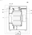
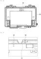
- FIG. 1 is a perspective view illustrating a laundry treating apparatus 1000 according to an embodiment of the present disclosure.
- FIG. 2 is a view schematically illustrating the main configuration of the laundry treating apparatus 1000 according to an embodiment of the present disclosure.
- the laundry treating apparatus 1000 includes a main body 100, a cabinet cover 200, and a control panel 300.
- the main body 100 is a part that accommodates laundry to perform processing operations for the laundry, and is capable of performing at least one of washing, rinsing, spin-drying, and drying.
- the main body 100 may include a washing tub 110 in which laundry is put into an internal space so that at least one of washing, rinsing, dehydration, and drying can be performed.
- a laundry inlet for putting laundry into the washing tub 110 may be provided on one surface of the washing tub 110.
- the laundry inlet may be configured to be opened/closed by a door 10 so that the laundry inlet can be closed by the door 10 during at least one of washing, rinsing, spin-drying, and drying.
- the washing tub 110 may include a tub configured to contain washing water.
- This tub may be placed on a damper installed on a base forming the bottom surface of the cabinet cover 200, is connected to a spring, which is installed inside the cabinet cover 200, in a suspended manner, and may be cushioned and supported by the damper and the spring.
- This tub has a cylindrical structure laid on its side, and a drum may be disposed inside the tub, and a motor, which is a driving mechanism configured to rotate the drum, may be installed on the rear surface of the tub.
- the drum is a part configured to accommodate laundry, may be configured as a cylindrical structure in which the lower portion is laid on its side like the tub to be submerged in the washing water in the tub, and may be rotatably disposed inside the tub.
- the drum has a plurality of holes provided in its peripheral portion to allow washing water or air to enter and exit therethrough, and a lifter configured to lift and drop laundry may be mounted on the inner circumferential surface of the peripheral portion.
- the cabinet cover 200 is a part that covers the main body 100 to form the exterior, and the main components of the main body 100 may be placed in the internal space of the cabinet cover.
- the above-mentioned door 10 may be installed on a portion of the cabinet cover 200.
- a controller 800 is installed inside the cabinet cover 200 to control the main components related to the processing operations of the laundry treating apparatus 1000 described above.
- a control panel 300 may be installed on the cabinet cover 200, and via the control panel 300, the laundry treating apparatus 1000 may display visual information related to the processing operations to a user and receive user input. That is, the control panel 300 may be provided for a user interface (UI).
- UI user interface
- control panel 300 may be installed in the front upper portion of the cabinet cover 200 to facilitate user access and operation.
- the cabinet cover 200 may have a first through hole 201 in the front upper end portion, and the control panel 300 may be disposed in this first through hole 201.
- a cabinet cover 200 that defines the exterior of the laundry treating apparatus 1000 may be designed as an integrated sheet metal product to achieve a seamless structure.
- control panel 300 disposed in the front upper end portion of the cabinet cover 200 to facilitate user access and operation also needs to match the exterior design of the laundry treating apparatus 1000, which is designed in a seamless structure.
- control panel 300 is installed inside the cabinet cover 200, and may be partially exposed outside through the first through hole 201 so that control signals for processing operations can be input by a user
- control panel 300 may be installed inside the cabinet cover 200, rather than being installed to be separated from the front surface of the cabinet cover 200 by a parting line.
- the control panel 300 is installed inside the cabinet cover 200 that forms the exterior so that the control panel 300 is not separated from the cabinet cover 200 on the exterior. Therefore, the aesthetics and productivity of the laundry treating apparatus 1000 can be improved by designing the cabinet cover 200 as an integrated sheet metal product.
- control panel 300 is installed inside the cabinet cover 200, and only a portion of the control panel 300 is exposed outside through the first through hole 201 in the cabinet cover 200. Therefore, by minimizing the exposure of portions of the control panel 300 that do not need to be exposed to a user, the exterior design of the laundry treating apparatus 1000 can be implemented in a seamless structure.
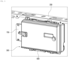
- FIG. 3 is a view illustrating the control panel 300 installed on the cabinet cover 200 in the laundry treating apparatus 1000 according to an embodiment of the present disclosure.
- FIG. 4 is an exploded perspective view illustrating the control panel 300 to be installed on the cabinet cover 200 in the laundry treating apparatus 1000 according to an embodiment of the present disclosure.
- FIGS. 5 and 6 are views illustrating a state in which the window 310 of the control panel 300 is attached to the inner surface of the cabinet cover 200 in the laundry treating apparatus 1000 according to an embodiment of the present disclosure.
- FIG. 7 is a view illustrating a state in which a coating guide 330 of the control panel 300 is fastened to the inner surface of the cabinet cover 200 in the laundry treating apparatus 1000 according to an embodiment of the present disclosure.
- control panel 300 includes a window 310, a touch screen 320, and a coating guide 330.
- the window 310 is a part in which the front surface other than the area corresponding to the first through hole 201 is bonded to the inner surface of the cabinet cover 200, and may have a structure in which a portion of the front surface of the control panel 300 is bonded to and supported on the inner surface of the cabinet cover 200.
- the window 310 has a relatively larger area than the first through hole 201, so that the central portion of the window 310 may be disposed in the first through hole 201, and the remaining outer portion may be bonded to the cabinet cover 200.
- the window 310 may have a step formed between the area corresponding to the first through hole 201 and the remaining portion. That is, the central portion of the window 310 may have a shape that protrudes forward from the remaining outer portion, so that the central portion of the window 310 can be inserted into the first through hole 201.
- the touch screen 320 is a part coupled to the rear surface of the window 310, and may be a screen configured to allow, when a touch object such as a human hand or an object (e.g., a stylus pen) touches the text displayed on the screen or a specific location of the screen, input data to be received directly from the screen so that the location can be identified and specific processing can be performed by stored software.
- a touch object such as a human hand or an object (e.g., a stylus pen) touches the text displayed on the screen or a specific location of the screen, input data to be received directly from the screen so that the location can be identified and specific processing can be performed by stored software.
- the touch screen 320 may be provided with touch sensors.
- the touch sensors may detect a touch input applied to the touch screen 320 using at least one of various touch types such as a resistive type, a capacitive type, an infrared type, an ultrasonic type, and a magnetic field type.
- control box may process the signals and then transmit corresponding data to a controller 800.
- the controller 800 may identify which areas of the touch screen 320 are touched, or the like.
- the control box may be a separate component from the controller 800 or may be the controller 800 itself.
- the controller 800 may perform different controls or the same control depending on the type of a touch object that touches the touch screen 320. Whether to perform different controls or the same controls depending on the type of the touch object may be determined depending on the operating state of the laundry treating apparatus 1000 or the running application.
- the touch screen 320 is capable of not only displaying visual information related to the processing operations of the laundry treating apparatus 1000 to the user, but also receiving user input for the processing operations of the laundry treating apparatus 1000.
- the touch screen 320 of the control panel 300 may simultaneously perform the functions of various display units for providing information to a user, as well as the functions of an input unit or a selection unit for user operation.
- the touch screen 320 may include at least one of a liquid crystal display (LCD), a thin film transistor-liquid crystal display (TFT LCD), an organic light-emitting Diode (OLED), a flexible display, a 3D Display, and an electronic ink (E-ink) display.
- LCD liquid crystal display
- TFT LCD thin film transistor-liquid crystal display
- OLED organic light-emitting Diode
- flexible display a 3D Display
- E-ink electronic ink
- the coating guide 330 is a part that is fastened to the inner surface of the cabinet cover 200 while supporting the touch screen 320 on the rear surface of the touch screen 320, and may have a structure in which a portion of the control panel 300 other than the front surface is fastened to and supported on the inner surface of the cabinet cover 200.
- the coating guide 330 may be fastened to the inner surface of the cabinet cover 200 by pressing the rear surface of the window 310 in the state in which the touch screen 320 is coupled to the front surface thereof.
- control panel 300 may have a structure in which a portion of the front surface of the overall structure is bonded to the inner surface of the cabinet cover 200, and a portion other than the front surface is fastened to the inner surface of the cabinet cover 200.
- the coating guide 330 on which the touch screen 320 is supported may be coated to prevent external moisture or the like from penetrating into the touch screen 320.
- the window 310 of the control panel 300 is bonded to the inner surface of the cabinet cover 200, and the coating guide 330, which supports the touch screen 320, is fastened to the inner surface of the cabinet cover 200, the control panel 300 directly coupled inside the cabinet cover 200 can be easily and stably installed.
- control panel 300 may further include a board cover 340 that is coupled to the rear surface of the coating guide 340 in the state in which a printed circuit board (PCB) 341 connected to the touch screen 320 is installed thereon.
- PCB printed circuit board
- the printed circuit board 341 may have various circuit components mounted thereon and be connected to the touch screen 320. Accordingly, input and output signals for the touch screen 320 may be connected to the controller 800 via the printed circuit board 341. In this case, the printed circuit board 341 may be the above-described control box or the controller 800 itself.
- a hole is provided in a portion of the coating guide 330 to make the front surface and the rear surface communicate with each other, so that the touch screen 320 and the printed circuit board 341 can be electrically connected to each other.
- the printed circuit board 341 may be installed on the board cover 340 and connected to the touch screen 320.
- the board cover 340 may be coupled to the rear surface of the coating guide 330 on the front surface of which the touch screen 320 is disposed, thereby allowing the touch screen 320 and the printed circuit board 341 to be disposed adjacent to each other.
- the board cover 340 on which the printed circuit board 341 is installed is coupled to the rear surface of the coating guide 330, the stably installed printed circuit board 341 can be easily connected to the touch screen 320.
- FIG. 8 is a view illustrating a state in which the panel frame 400 presses the rear surface of the control panel 300 in the laundry treating apparatus 1000 according to an embodiment of the present disclosure.
- the laundry treating apparatus 1000 may further include a panel frame 400 configured to press the rear surface of the control panel 300 and coupled to the inner surface of the cabinet cover 200.
- control panel 300 Even when the control panel 300 is installed inside the cabinet cover 200 with the above-described structure, the control panel 300 may be removed due to shock, vibration, or the like.
- control panel 300 installed inside the cabinet cover 200 in the manner of applying force inward from the outside of the cabinet cover 200, there is a risk that the control panel 300 may be detached toward the rear side when used continuously.
- the panel frame 400 configured to press the rear surface of the control panel 300 is coupled to the inner surface of the cabinet cover 200, it is possible to prevent the control panel 300 from being removed by shock, vibration, and the like.
- the panel frame 400 may be provided with a frame protrusion 410 that protrudes from the front surface thereof to be capable of pressing the rear surface of the board cover 340.
- the frame protrusions 410 protrudes from the front surface of the panel frame 400, and a portion of this frame protrusion 410 has a bent shape, there is room for elastic deformation when an external force is applied thereto.
- the frame protrusion 410 that presses the rear surface of the control panel 300 can absorb the shock and vibration while being elastically deformed.
- control panel 300 may further include a first sealing member 361 interposed between the window 310 and the coating guide 330.
- the touch screen 320 is disposed between the window 310 and the coating guide 330, there is a risk that the touch screen 320 may be damaged when the space between the window 310 and the coating guide 330 is excessively narrow.
- the first sealing member 361 between the window 310 and the coating guide 330 to prevent moisture from penetrating into the portions that the coating guide 330 does not cover.
- the first sealing member 361 is interposed between the window 310 and the coating guide 330, waterproofing and shock resistance performance can be secured at the coupling portion between the window 310 and the coating guide 330.
- control panel 300 may further include a second sealing member 362 interposed between the coating guide 330 and the board cover 340.
- the printed circuit board 341 is disposed between the coating guide 330 and the board cover 340, there is a risk that the printed circuit board 341 may be damaged when the space between the coating guide 330 and the board cover 340 is excessively narrow.
- the second sealing member 362 may be desirable to interpose the second sealing member 362 between the coating guide 330 and the board cover 340 to prevent moisture from penetrating into the portions that the board cover 340 does not cover.
- the second sealing member 362 is interposed between the coating guide 330 and the board cover 340, waterproofing and shock resistance performance can be secured at the coupling portion between the coating guide 330 and the board cover 340.
- FIG. 9 is a view illustrating in more detail the hook protrusion 210 on the cabinet cover 200 in the laundry treating apparatus 1000 according to an embodiment of the present disclosure.
- the cabinet cover 200 may have a hook protrusion 210 that protrudes rearward from the circumference of a second through hole 202 provided lower than the center of the first through hole 201.
- the control panel 300 may be fastened to the hook protrusion 210 and coupled to the inner surface of the cabinet cover 200.
- the control panel 300 is fastened to the hook protrusion 210 protruding from the second through hole 202 provided in the cabinet cover 200, manufacturing efficiency can be improved by forming the hook protrusion 210 for fastening the control panel 300 at the time of forming the second through hole 202.
- the hook protrusion 210 may have a hook hole 211 penetrating the hook protrusion in the longitudinal direction thereof.
- the coating guide 330 may be fastened when the hook 370 provided at the lower end thereof is inserted into the hook hole 211.
- the control panel 300 can be easily and stably fastened to the hook protrusion 210.
- the upper end portion of the coating guide 330 may be screwed to the inner surface of the cabinet cover 200.
- the laundry treating apparatus 1000 since the upper end portion of the coating guide 330 is screwed to the inner surface of the cabinet cover 200, the coupled state between the cabinet cover 200 and the control panel 300 can be stably maintained.
- the laundry treating apparatus 1000 may further include a control button 500 installed inside the cabinet cover 200 and partially exposed outside through the second through hole 202 to be brought into contact with the control panel 300 when pressed by a user
- control button 500 is installed inside the cabinet cover 200 and the control button 500 is partially exposed outside through the second through hole 202 in the cabinet cover 200, input of control signals for which an intuitive operation, such as a power on/off signal and a start/stop operation signal, is desirable can be performed smoothly.
- a pair of second through holes 202 and control buttons 500 may each be arranged symmetrically on opposite sides of the control panel 300.
- the second through holes 202 and the control buttons 500 are each arranged symmetrically on the opposite sides of the control panel 300, a plurality of control signals can be input through the control buttons 500 and a balance in the exterior design can be achieved.
- the hook protrusions 210 may be provided at the second through holes 202, respectively.
- the control panel 300 may be fastened to both the respective hook protrusions 210.
- control panel 300 since the control panel 300 is fastened to both the respective hook protrusions 210 provided at the pair of second through holes 202, respectively, the control panel 300 can be fastened to the hook protrusions 210 while maintaining balance.
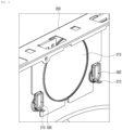
- the laundry treating apparatus 1000 may further include a wireless communication part 600 installed inside the cabinet cover 200 to be capable of transmitting and receiving wireless signals to and from the outside.
- the wireless communication part 600 may be installed on the inner surface of the cabinet cover 200 while being coupled to the bottom of the control panel 300.
- the wireless communication part 600 is installed on the inner surface of the cabinet cover 200 in the state of being coupled to the bottom of the control panel 300, main components can be efficiently arranged in the internal space of the cabinet cover 200, and the control panel 300 can be disposed higher in the front upper end portion of the cabinet cover 200.
- FIG. 10 is a view illustrating, by way of an example, a fixed UI section 301 and a variable UI section 302 of the control panel 300 in the laundry treating apparatus 1000 according to an embodiment of the present disclosure.
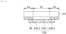
- FIG. 11A is a view illustrating, by way of an example, a transmissive area 311 and a non-transmissive area 312 of the control panel 300 in the laundry treating apparatus 1000 according to an embodiment of the present disclosure.
- FIGS. 11B and 11C are views illustrating a button rod 390 contact type of the control panel 300 in the laundry treating apparatus according to an embodiment of the present disclosure.
- FIGS. 12 to 14 are views illustrating the structure of providing the transmissive area 311 and the non-transmissive area 312 of the control panel 300 in the laundry treating apparatus 1000 according to an embodiment of the present disclosure.
- control panel 300 may include a fixed UI section 301 in which a first control UI 301a, of which the display is fixed, is disposed, and a variable UI section 302 in which a second control UI 302a, of which the display-on/off and type are variable, is disposed.
- the laundry treating apparatus 1000 since the fixed UI section 301 and the variable UI section 302 provided in the control panel 300 are arranged according to UI characteristics, a user may more conveniently input control signals for processing operations.
- a portion of an area of the window 310 corresponding to the first through hole 201 may be provided as a transmissive area 311, and the remaining portion is provided as a non-transmissive area 312.
- the touch screen 320 may be coupled to the rear surface of the window 310 and perform display through the transmissive area 311.
- the touch screen 320 is displayed through the transmissive area 311 provided in a portion of the window 310, and the remaining portion of the window 310 is provided as a non-transmissive area 312, various exterior designs may be implemented regardless of the shape of the touch screen 320.
- the laundry treating apparatus 1000 may include a main body 100, a cabinet cover 200, a control panel 300, and a control button 500.
- the main body 100 is a part that accommodates laundry to perform processing operations for the laundry, and is capable of performing at least one of washing, rinsing, spin-drying, and drying.
- the cabinet cover 200 is a part that covers the main body 100 to form an exterior and has a first through hole 201 provided in the front upper portion thereof, and a second through hole 202 provided lower than the center of the first through hole 201.
- the first through hole 201 may be provided in the cabinet cover 200 to allow a portion of the control panel 300 to be exposed outside.
- the second through hole 202 may be provided lower than the center of the first through hole 201, so that a control button 500 can be disposed therein.
- the control panel 300 is a part that is installed inside the cabinet cover 200 and partially exposed outside through the first through hole 201 so that control signals for processing operations can be input by a user
- the control button 500 is a part that is installed inside the cabinet cover 200 and partially exposed outside through the second through hole 202 to be capable of coming into contact with the control panel 300 when pressed by a user
- control button 500 when the control button 500 is installed inside the cabinet cover 200, only the portion for a user to operate may be exposed outside through the second through hole 202. Accordingly, the user may input specific control signals associated with the control button 500 to the laundry treating apparatus 1000 by pressing the portion of the control button 500 exposed outside the cabinet cover 200.
- control buttons 500 are essentially used due to the characteristics thereof, such as a power on/off signal and an operation start/stop signal, but the types thereof do not need to be changed. It may be desirable to arrange the control signals such that the user can intuitively operate the control signals.
- the signals such as a power on/off signal and an operation start/stop signal such that a user can operate the signals through the control button 500, which is fixedly installed separately from the control panel 300.
- the portions of the control buttons 500 disposed inside the cabinet cover 200 come into contact with the control panel 300 so that signals such as a power on/off signal and an operation start/stop signal can be input to the controller 800.
- the portion of the control button 500 disposed inside the cabinet cover 200 may not come into contact with the control panel 300, but signals such as turn on/off and operation start/stop may be input to the controller 800 through a separate signal transmission path.
- the cabinet cover 200 may have a hook protrusion 210 protruding rearward from the circumference of the second through hole 202, and the control panel 300 may be coupled to the inner surface of the cabinet cover 200 while being fastened to the hook protrusion 210.
- the circumference of the second through hole 202 provided through the cabinet cover 200 may be partially bent toward the rear side to provide the hook protrusion 210.
- the hook protrusion 210 is not a separate member coupled to the second through hole 202 of the cabinet cover 200, but may be formed by bending integrally with the second through hole 202 which is formed when the cabinet cover 200 is manufactured as a sheet metal product.
- control panel 300 may be configured in a structure that is supported by being fastened to the hook protrusion 210 provided integrally with the circumference of the second through hole 202.
- the hook hole 211 may penetrate the hook protrusion 210 in the longitudinal direction thereof, and the control panel 300 may be fastened when the hook 370 is inserted into the hook hole 211.
- the hook protrusion 210 may have a shape protruding rearward from the circumference of the second through hole 202, and the hook hole 211 may be provided in a shape penetrating the hook protrusion 210 in the longitudinal direction.
- the hook 370 may protrude at the lower end portion of the control panels 300, and the hook 370 may be inserted into and fastened to the hook hole 211 having the shape penetrating the hook protrusion in the longitudinal direction.
- the hook 370 at the lower end portion of the control panel 300 may be easily fastened to the hook protrusion 210 protruding rearward from the circumference of the second through hole 202.
- the forward and rearward displacement of the control panel 300 can be limited by the hook protrusion 210.
- a portion of the control panel 300 may be seated on the upper surface of the hook protrusion 210 so that the upward and downward displacement of the control panel 300 can also be limited to a certain extent.
- the control panel 300 can be easily and stably fastened to the hook protrusion 210.
- the upper end portion of the control panel 300 may be screwed to the inner surface of the cabinet cover 200.
- the upper end portion of the control panel 300 may be fastened to the cabinet cover 200 through at least one screw 380.
- a pair of second through holes 202 and control buttons 500 may be arranged symmetrically on opposite sides of the control panel 300.
- second through holes 202 may be provided symmetrically on the left and right sides of the control panel 300, respectively.
- a control button 500 may be disposed in each of the second through holes 202.
- one control button 500 may be associated with a power on/off signal, and another control button 500 may be associated with an operation start/stop signal.
- the second through holes 202 and the control buttons 500 are each arranged as a symmetrical pair on the opposite sides of the control panel 300, a plurality of control signals can be input through the control buttons 500 and a balance in the exterior design can be achieved.
- the hook protrusions 210 may be provided at the second through holes 202, respectively, and the control panel 300 may be fastened to both the respective hook protrusions 210.
- second through holes 202 may be provided symmetrically on the left and right of the control panel 300, and hook protrusions 210 may be provided for the second through holes 202, respectively.
- a pair of hooks 370 may be provided at the lower end portion of the control panel 300 so that the hooks 370 can be fastened to the hook protrusions 210, respectively.
- control panel 300 since the control panel 300 is fastened to both the respective hook protrusions 210 provided at the pair of second through holes 202, respectively, the control panel 300 can be fastened to the hook protrusions 210 while maintaining balance.
- the laundry treating apparatus 1000 may include a main body 100, a cabinet cover 200, a control panel 300, and a wireless communication part 600.
- the wireless communication part 600 may be installed on the inner surface of the cabinet cover 200 while being coupled to the bottom of the control panel 300.
- the wireless communication part 600 is a part that is installed inside the cabinet cover 200 and configured to transmit and receive wireless signals to the outside.
- the wireless communication part may be configured to receive signals, which are wirelessly input from outside the laundry treating apparatus 1000, and to transmit the signals to the controller 800, or may be configured to wirelessly transmit signals, which are output from the controller 800, to outside the laundry treating apparatus 1000.
- the wireless communication part 600 may include at least one of Wi-Fi, Bluetooth, and RF communication modules.
- the laundry treating apparatus 1000 may be configured to perform wireless communication with a user's mobile terminal via a Wi-Fi communication module or a Bluetooth communication module.
- the laundry treating apparatus 1000 may be configured to perform wireless communication with another home appliance (e.g., another separate laundry treating apparatus 1000) via an RF communication module.
- the wireless communication part 600 may be disposed in the internal space of the cabinet cover 200. However, it may be desirable for the wireless communication part to be disposed as close to the external portion of the cabinet cover 200 as possible in the internal space of the cabinet cover 200 in order to minimize a decrease in wireless communication efficiency.
- the cabinet cover 200 is made of a metal material, in order ensure that the wireless communication part 600 performs wireless communication smoothly, it may be desirable for the wireless communication part 600 to be disposed adjacent to the first through hole 201 or the second through hole 202 in the cabinet cover 200.
- the wireless communication part 600 since it is more efficient for the wireless communication part 600 to be disposed adjacent to the control panel 300 and the printed circuit board 341, it may be more desirable for the wireless communication part 600 to be installed together with the control panel 300.
- the wireless communication part 600 may be installed on the inner surface of the cabinet cover 200 in the state of being coupled to the control panel 300, rather than being installed separately from the control panel 300.
- the overall height of the laundry treating apparatus 1000 is generally less than the height of the user's eyes, in order for the user to more easily check and operate the control panel 300, it may be desirable for the control panel 300 to be disposed as high as possible in the front upper end portion of the cabinet cover 200.
- the first through hole 201 configured to expose a portion of the control panel 300 outside the cabinet cover 200 also needs to be disposed as high as possible in the front upper end portion of the cabinet cover 200.
- control panel 300 when a separate main component is disposed on top of the control panel 300, it may be difficult to dispose the control panel 300 and the first through hole 201 as high as possible in the front upper end portion of the cabinet cover 200.
- the wireless communication part 600 is installed on the inner surface of the cabinet cover 200 in the state of being coupled to the bottom of the control panel 300, main components can be efficiently arranged in the internal space of the cabinet cover 200, and the control panel 300 can be disposed higher in the front upper end portion of the cabinet cover 200.
- the laundry treating apparatus 1000 may further include a sound output unit 700 that is installed inside the cabinet cover 200 and configured to output sound signals for processing operations.
- the sound output unit 700 may be installed on the inner surface of the cabinet cover 200 while being coupled to a side surface of the control panel 300.
- the sound output unit 700 is a component that guides the user to specific matters or draws the user's attention to the specific matters by an auditory sound signal, such as a buzzer or speaker, and may be configured in various ways according to need.
- the sound output unit 700 may be disposed in the internal space of the cabinet cover 200. However, it may be desirable for the sound output unit to be disposed as close to the external portion of the cabinet cover 200 as possible in the internal space of the cabinet cover 200 in order to insure that sound signals are smoothly transmitted to the user
- the sound output unit 700 since it is also more efficient for the sound output unit 700 to be disposed adjacent to the control panel 300 and the printed circuit board 341, it may be more desirable for the sound output unit 700 to be installed together with the control panel 300.
- the sound output unit 700 may also be installed on the inner surface of the cabinet cover 200 in the state of being coupled to the control panel 300, rather than being installed separately from the control panel 300.
- the sound output unit 700 it is not desirable for the sound output unit 700 to be coupled to the top of the control panel 300. In addition, in order to minimize interference with the wireless communication part 600 coupled to the bottom of the control panel 300, it may be desirable for the sound output unit 700 to be coupled to a side surface of the control panel 300.
- the sound output unit 700 since the sound output unit 700 is installed on the inner surface of the cabinet cover 200 in the state of being coupled to the side surface of the control panel 300, the sound output unit 700 may also be arranged to match the most efficient arrangement of the control panel 300.
- the laundry treating apparatus 1000 the configuration in which the wireless communication part 600 and the sound output unit 700 are disposed at the bottom of the control panel 300 and on the side surface of the control panel 300, respectively, has been described, but the laundry treating apparatus is not necessarily limited thereto. If necessary, the wireless communication part 600 and the sound output unit 700 may be disposed on the side surface of the control panel 300 and at the bottom of the control panel 300, respectively.
- both the wireless communication part 600 and the sound output unit 700 may be disposed at the bottom of the control panel 300, or disposed on the side surface of the control panel 300.
- control panel 300 may include a window 310, a touch screen 320, and a coating guide 330 so that the control panel 300 directly coupled inside the cabinet cover 200 can be easily and stably installed.
- the wireless communication part 600 may be coupled to the bottom of the coating guide 330, and the sound output unit 700 may be coupled to the side surface of the coating guide 330.
- the coating guide 330 is a part that supports the touch screen 320.
- the coating guide 330 may be most desirable for coupling with other components.
- the wireless communication part 600 and the sound output unit 700 are coupled to the bottom and the side surface of the coating guide 330, respectively, the communication part 600 and the sound output unit 700 can be coupled to the most desirable portions in the control panel 300.
- the laundry treating apparatus 1000 may include a main body 100, a cabinet cover 200, and a control panel 300.
- the control panel 300 may include a fixed UI section 301 and a variable UI section 302.
- the control panel 300 is a part that is exposed outside the cabinet cover 200 so that the user can input control signals for the laundry treating apparatus 1000.
- the user may input operating signals for each component of the laundry treating apparatus 1000 by operating the control panel 300.
- UIs are disposed on the control panel 300, so that the user can may operate the UIs disposed on the control panel 300 to input operating signals for each component of the laundry treating apparatus 1000.
- the UIs there may be a UI that is essentially used due to its characteristics, but whose display does not need to be changed.
- the UIs disposed on the control panel 300 are operated differently by the user depending on the characteristics thereof, it may be desirable to arrange respective UIs separately in consideration of the characteristics thereof so that the user can use the UIs more conveniently.
- a first control UI 301a of which the display is fixed, may be disposed in the fixed UI section 301.
- the first control UI 301a e.g., a setting UI
- the user may recognize that the first control UI is always disposed at that on the control panel 300.
- a second control UI 302a of which the status and type are variable may be disposed in the variable UI section 302.
- the second control UI 302a needs to be used while varying to various types due to its characteristics, and the user needs to operate the second control UI while checking the status and type of the currently implemented UI.
- the laundry treating apparatus 1000 since the fixed UI section 301 and the variable UI section 302 provided in the control panel 300 are arranged according to UI characteristics, the user may more conveniently input control signals for processing operations.
- operation signals for the first control UI 301a may be input to the fixed UI section 301 by a button rod contact type.
- the button rod contact type may refer to a contact type with a structure in which, when a user operates the fixed UI section 301, a separate button rod 390 capable of connecting electrical signals moves and transmits the corresponding signals to the control box or controller 800.
- the button rod 390 arranged to be brought into brought into a corresponding portion at one end is pressed and pushed rearward.
- an electrical signal may be connected, and as a result, the control signal that the user wishes to input may be transmitted to the controller 800.
- the first control UI 301a disposed in the fixed UI section 301 may be controlled by a simple operation by the user without the need to change the display. Therefore, the button rod contact type that is relatively easy to operate may be desirable for the first control UI.
- the fixed UI section 301 is operated by the button rod contact type, the user may easily operate the fixed UI section 301, of which the display is fixed.
- operation signals for the second control UI 302a may be input to the variable UI section 302 by a touch type.
- the touch type may refer to a contact type with a structure in which, when a touch object such as a human hand or an object (e.g., a stylus pen) touches the second control UI 302a appearing in the variable UI section 302 through a separate touch sensor or the like, a corresponding signal can be transmitted to the control box or the controller 800.
- a touch object such as a human hand or an object (e.g., a stylus pen) touches the second control UI 302a appearing in the variable UI section 302 through a separate touch sensor or the like
- a corresponding signal can be transmitted to the control box or the controller 800.
- the touch type which allows the user to operate the UI while checking the status and type of the UI that is being implemented by the user, may be desirable for the second control UI.
- the type of the second control UI 302a also varies in the variable UI section 302, it may be convenient to allow various types of UIs to vary through touching on a screen of a certain area.
- variable UI section 302 is operated by a touch type, the user may effectively operate the variable UI section 302 of which the display-on/off and type vary.
- the first control UI 301a may include at least one of a power UI on which power-on/power-off of the laundry treating apparatus 1000 can be selected, and an operation UI on which turn-on/turn-off of the operation of the laundry treating apparatus 1000 can be selected, and a setting UI on which the settings of the laundry treating apparatus 1000 can be selected.
- the second control UI 302a is an operation UI on which the operation type of the laundry treating apparatus 1000 can be selected, a laundry UI on which the type of laundry accommodated in the laundry treating apparatus 1000 can be selected, and a time UI on which the operating time of the laundry treating apparatus 1000 can be selected.
- the operation UI is used to set the process to be performed for laundry in the laundry treating apparatus 1000. It is necessary to operate the operation UI while checking the status and type of the UI that is currently being implemented.
- the laundry UI is used to select the type of laundry to be processed in the laundry treating apparatus 1000 so that optimal processing can be performed accordingly. It is necessary to operate the laundry UI while checking the status and type of a UI that is currently being implemented.
- the time UI is used to set the time for processing laundry in the laundry treating apparatus 1000. It is also necessary to operate the time UI while checking the status and type of a UI that is currently being implemented.
- variable UI section 302 it may be desirable to dispose the operation UI, the laundry UI, and the time UI in the variable UI section 302 to be variable in terms of display-on/off and type.
- control panel 300 may include a window 310, a touch screen 320, and a coating guide 330 so that the control panel 300 directly coupled inside the cabinet cover 200 can be easily and stably installed.
- the touch screen 320 may be disposed in the variable UI section 302.
- the touch screen 320 is a screen configured to: determine, when a touch object such as a human hand or an object (e.g., a stylus pen) touches a character displayed on the screen or a specific location on the screen, the location; and allow an input material to be received directly therefrom so specific processing can be executed by stored software.
- the controller 800 may change the display-on/off and type to correspond to the type of the touch object touching the touch screen 320.
- variable UI section 302 in which display-on/off and type vary can be smoothly implemented on the touch screen 320.
- the first through hole 201 may be provided as a circular open surface.
- the touch screen 320 may be fabricated in a quadrilateral shape with a height Hs that is relatively smaller than the diameter Dh of the first through hole 201.
- the touch screen 320 since the touch screen 320 has a height relatively smaller than the diameter of the first through hole 201 provided in a circular shape, it may be possible to implement a circular display on the exterior design even when the touch screen 320 is not fabricated in a relatively expensive circular structure.
- a portion of an area of the window 310 corresponding to the first through hole 201 may be provided as a transmissive area 311, and the remaining portion is provided as a non-transmissive area 312.
- the touch screen 320 may be coupled to the rear surface of the window 310 and perform display through the transmissive area 311.
- the touch screen 320 is displayed through the transmissive area 311 provided in a portion of the window 310, and the remaining portion of the window 310 is provided as a non-transmissive area 312, various exterior designs may be implemented regardless of the shape of the touch screen 320.
- the laundry treating apparatus 1000 may include a main body 100, a cabinet cover 200, and a control panel 300.
- the control panel 300 may include a window 310 and a touch screen 320.
- a portion of an area of the window 310 corresponding to the first through hole 201 may be provided as a transmissive area 311 and the remaining portion may be provided as a non-transmissive area 312.
- the touch screen 320 may be coupled to the rear surface of the window 310 and perform display through the transmissive area 311.
- the transmissive area 311 refers to an area configured to transmit at least part of the light such that the opposite side or the inside is visible. Accordingly, the transmissive area 311 may be a concept that includes a semi-transmissive area.
- the window 310 may be made of a transmissive material. That is, the window 310 may be made of a transmissive glass material or a synthetic resin material.
- a shield layer 312a may be disposed on a portion of the window 310 to provide a non-transmissive area 312.
- the shield layer 312a may be disposed on the front or rear surface of the window 310.
- ink is printed on the rear surface of the window 310 to form the shield layer 312a.
- the ink may contain pigments having a specific color group (e.g., black, white, and blue).
- various printing techniques such as screen printing (using a mesh formed of silk, nylon, tetron, stainless steel, or the like), offset printing, and transfer printing may be applied.
- the shield layer 312a is not disposed in the transmissive area 311. That is, the transmissive area 311 may be a transparent portion that is not covered by the shield layer 312a and remains as a transmissive window 310.
- a touch screen 320 may be coupled to the rear surface of the window 310 corresponding to the transmissive area 311.
- the touch screen 320 may be disposed to completely cover the transmissive area 311 to detect a touch input to the transmissive area 311.
- the touch screen 320 may be fabricated to have a size larger than the transmissive area 311, and in this case, the touch screen 320 may be configured to cover a portion of the shield layer 312a that defines the transmissive area 311.
- the shield layer 312a defining the transmissive area 311 of the window 310 may be configured such that its transparency gradually changes toward the transmissive area 311.
- the non-transmissive area 312 around the transmissive area 311 may be configured to gradually become transparent toward the transmissive area 311.
- the shield layer 312a may include a plurality of shield dots 312a-1 provided around the transmissive area, and the plurality of shield dots 312a-1 may be provided to have a lower density toward the transmissive area 311.
- a film 312b may be bonded to the rear surface of the window 310 to provide the non-transmissive area 312.
- the film 312b may include a non-transmissive portion 312b-2 corresponding to the non-transmissive area and a transmissive portion 312b-1 corresponding to the transmissive area 311.
- the non-transmissive portion 312b-2 is provided to surround the transmissive portion 312b-1, and the transmissive portion 312b-1 may be partitioned by the non-transmissive portion 312b-2.
- the portion corresponding to the non-transmissive portion 312b-2 may function as a shield layer 312a that makes the window 310 opaque, thereby forming the non-transmissive area 312.
- the portion corresponding to the transmissive portion 312b-1 may form the transmissive area 311 together with the transmissive window 310.
- a touch screen 320 may be coupled to the rear surface of the film 312b corresponding to the transmissive portion 312b-1.
- the touch screen 320 may be disposed to completely cover the transmissive area 311 to detect a touch input to the transmissive area 311.
- the touch screen 320 may be provided in a size larger than the transmissive area 311, and in this case, the touch screen 320 may be configured to cover a portion of the non-transmissive portion 312b-2 that defines the transmissive portion 312b-1.
- the touch screen 320 may be fabricated in a shape having a flat surface relatively smaller than the open surface of the first through hole 201, and in the area corresponding to the first through hole 201 in the window 310, the portion in which the touch screen 320 does not perform display may be provided as a non-transmissive area 312.
- the portion through which the control panel 300 is externally exposed i.e., the first through hole 201
- the portion through which the control panel 300 is externally exposed may have various shapes.
- the shape of the first through hole 201 is provided in various ways in terms of a design, if the planar shape of the touch screen 320 for display does not match the shape of the first through hole 201, there is a risk that aesthetics may be deteriorated.
- the first through hole 201 is opened relatively larger than the touch screen 320, and the portion of the through hole 201 where the touch screen 320 is not displayed is covered by the non-transmissive area 312 of the window 310. Therefore, it is possible to implement a design in which only the touch screen 320 is displayed even when the open shape of the first through hole 201 does not correspond to the planar shape of the touch screen 320.
- the first through hole 201 may be provided as a circular open surface, and the touch screen 320 be fabricated in a quadrilateral shape with a height Hs that is relatively smaller than the diameter Dh of the first through hole 201.
- the circular shape may include a true circular shape, an oval shape, or a round shape which is at least partially rounded.
- the circular touch screen 320 may be more expensive than the widely used quadrilateral touch screen 320, and since it is difficult to determine the exact installation location due to its shape, assembly defects may occur frequently.
- control panel 300 that appears circular to the user while using the quadrilateral touch screen 320 that is inexpensive and can be assembled in the correct position.
- transmissive area 311 is surrounded by the non-transmissive area 312, visual information output from a portion of the touch screen 320 that does not correspond to the transmissive area 311 is invisible to the user. Considering this, visual information may not be output on a portion of the touch screen 320 that does not correspond to the transmissive area 311.
- the touch screen 320 since the touch screen 320 has a height relatively smaller than the diameter of the first through hole 201 provided in a circular shape, it may be possible to implement a circular display on the exterior design even when the touch screen 320 is not fabricated in a relatively expensive circular structure.
- control panel 300 may include a fixed UI section 301 in which a first control UI 301a, of which the display is fixed, is disposed, and a variable UI section 302 in which a second control UI 302a, of which the display-on/off and type are variable, is disposed. Therefore, control signals for processing operations can be more conveniently input by the user.
- the fixed UI section 301 may be provided as a non-transmissive area 312, and the variable UI section 302 may be provided as the transmissive area 311.
- variable UI section 302 since the touch screen 320 is disposed in the variable UI section 302, the variable UI section 302 needs to be formed as a transmissive area 311. In contrast, it may be desirable to provide the fixed UI section 301 as a non-transmissive area 312 and to dispose only UIs that are relatively simple to operate in the fixed UI section.
- variable UI section 302 of the control panel 300 since the fixed UI section 301 and the variable UI section 302 of the control panel 300 are provided as the non-transmissive area 312 and the transmissive area 311, respectively, the variable UI section 302, of which the display-on/off and type vary, may be implemented on the touch screen 320.
- an operation signal for the first control UI 301a is input by the button rod contact type, so that the user can easily operate the fixed UI section 301, of which the display is fixed.
- the laundry treating apparatus 1000 since an operating signal for the second control UI 302a is input by the touch type in the variable UI section 302, the user may effectively operate the variable UI section 302, of which the display-on/off and type vary.
- the control panel is installed inside the cabinet cover that defines the exterior, and the control panel is not separated from the cabinet cover on the exterior. Therefore, the cabinet cover is designed as an integrated sheet metal product, so that the aesthetics and productivity of laundry treating apparatus can be improved.
- control panel is installed inside the cabinet cover, and only a portion of the control panel is exposed outside through the first through hole provided in the cabinet cover. Therefore, the exterior design of the laundry treating apparatus can be implemented as a seamless structure by minimizing the exposure of the portions of the control panel that do not need to be exposed to the user.
- control panel is fastened to the hook protrusion protruding from the second through hole provided in the cabinet cover. Therefore, manufacturing efficiency can be improved by forming the hook protrusion for fastening the control panel when forming the second through hole.
- the hook at the lower end portion of the control panel is inserted into and fastened to the hook hole penetrating the hook protrusion in the longitudinal direction. Therefore, the control panel can be easily and stably fastened to the hook protrusion.
- the upper end portion of the control panel is screwed to the inner surface of the cabinet cover. Therefore, the coupling state between the cabinet cover and the control panel can be stably maintained.
- a pair of second through holes and control buttons are arranged as a symmetrical pair on opposite sides of the control panel. Therefore, a plurality of control signals can be input through the control buttons, and a balance on exterior design can be achieved.
- control panel is fastened both to the hook protrusions provided at the pair of second through holes, respectively. Therefore, the control panel can be fastened to the hook protrusions while maintaining balance.
- the window of the control panel is bonded to the inner surface of the cabinet cover, and the coating guide supporting the touch screen is fastened to the inner surface of the cabinet cover. Therefore, the control panel, which is directly coupled inside the cabinet cover, can be more easily and stably installed.
- the board cover on which the printed circuit board is installed is coupled to the rear surface of the coating guide. Therefore, the stably installed printed circuit board can be easily connected to the touch screen.
- the panel frame which presses the rear surface of the control panel, is coupled to the inner surface of the cabinet cover. Therefore, the control panel can be prevented from being detached due to shock, vibration, or the like.
- the frame protrusion provided on the panel frame presses the rear surface of the board cover.
- shock and vibration applied to the control panel can be alleviated to a certain extent.
- the first sealing member is interposed between the window and the coating guide. Therefore, waterproofing and impact resistance performance can be secured for the coupling portion between the window and the coating guide.
- the second sealing member is interposed between the coating guide and the board cover. Therefore, waterproofing and impact resistance performance can be secured for the coupling portion between the coating guide and the board cover.
- the wireless communication part is installed on the inner surface of the cabinet cover in a state of being coupled to the bottom of the control panel. Therefore, the main components can be efficiently disposed in the internal space of the cabinet cover, and the control panel can be disposed higher at the front upper end portion of the cabinet cover.
- UIs are arranged in the fixed UI section and the variable UI section, respectively, which are provided in the control panel, depending on the characteristics of thereof. Therefore, control signals for processing processes can be more conveniently input by the user.
- the touch screen is displayed through the transmissive area provided in a portion of the window, and the remaining portion of the window is provided as the non-transmissive area. Therefore, various exterior designs can be implemented regardless of the shape of the touch screen.
Landscapes
- Engineering & Computer Science (AREA)
- Textile Engineering (AREA)
- Computer Networks & Wireless Communication (AREA)
- Main Body Construction Of Washing Machines And Laundry Dryers (AREA)
Applications Claiming Priority (2)
| Application Number | Priority Date | Filing Date | Title |
|---|---|---|---|
| KR1020230000730A KR20240109050A (ko) | 2023-01-03 | 2023-01-03 | 세탁물 처리기기 |
| PCT/KR2023/014287 WO2024147433A1 (ko) | 2023-01-03 | 2023-09-20 | 세탁물 처리기기 |
Publications (2)
| Publication Number | Publication Date |
|---|---|
| EP4459028A1 true EP4459028A1 (de) | 2024-11-06 |
| EP4459028A4 EP4459028A4 (de) | 2025-06-18 |
Family
ID=91803716
Family Applications (1)
| Application Number | Title | Priority Date | Filing Date |
|---|---|---|---|
| EP23914898.4A Pending EP4459028A4 (de) | 2023-01-03 | 2023-09-20 | Wäschebehandlungsvorrichtung |
Country Status (5)
| Country | Link |
|---|---|
| US (1) | US20250154707A1 (de) |
| EP (1) | EP4459028A4 (de) |
| KR (1) | KR20240109050A (de) |
| CN (1) | CN222795989U (de) |
| WO (1) | WO2024147433A1 (de) |
Family Cites Families (9)
| Publication number | Priority date | Publication date | Assignee | Title |
|---|---|---|---|---|
| KR100434295B1 (ko) * | 2002-03-08 | 2004-06-05 | 엘지전자 주식회사 | 드럼세탁기의 컨트롤패널 어셈블리 조립구조 |
| KR101122071B1 (ko) * | 2004-06-24 | 2012-03-15 | 엘지전자 주식회사 | 드럼 세탁기 |
| KR20070066604A (ko) * | 2005-12-22 | 2007-06-27 | 엘지전자 주식회사 | 세탁기의 엘이디 서포터 방수 구조 |
| KR101364879B1 (ko) * | 2006-12-19 | 2014-02-20 | 엘지전자 주식회사 | 세탁기 및 세탁기의 제조방법 |
| EP2896735A4 (de) * | 2012-09-14 | 2015-07-22 | Panasonic Ip Man Co Ltd | Waschmaschine |
| JP6254920B2 (ja) * | 2014-09-19 | 2017-12-27 | 日立アプライアンス株式会社 | 洗濯機 |
| KR102257622B1 (ko) | 2014-12-17 | 2021-05-28 | 엘지전자 주식회사 | 세탁장치 |
| KR102501691B1 (ko) * | 2016-03-25 | 2023-02-21 | 삼성전자주식회사 | 세탁기 |
| KR102709013B1 (ko) * | 2021-06-28 | 2024-09-24 | 엘지전자 주식회사 | 의류처리장치 |
-
2023
- 2023-01-03 KR KR1020230000730A patent/KR20240109050A/ko active Pending
- 2023-09-20 EP EP23914898.4A patent/EP4459028A4/de active Pending
- 2023-09-20 WO PCT/KR2023/014287 patent/WO2024147433A1/ko not_active Ceased
- 2023-09-20 CN CN202390000214.1U patent/CN222795989U/zh active Active
- 2023-09-20 US US18/838,713 patent/US20250154707A1/en active Pending
Also Published As
| Publication number | Publication date |
|---|---|
| WO2024147433A1 (ko) | 2024-07-11 |
| CN222795989U (zh) | 2025-04-25 |
| US20250154707A1 (en) | 2025-05-15 |
| EP4459028A4 (de) | 2025-06-18 |
| KR20240109050A (ko) | 2024-07-10 |
Similar Documents
| Publication | Publication Date | Title |
|---|---|---|
| EP3162947B1 (de) | Wäschebehandlungsvorrichtung | |
| EP1970479A2 (de) | Kontrolltafel und Waschmaschine mit derselben | |
| EP4455390A1 (de) | Wäscheverarbeitungsvorrichtung | |
| EP4459028A1 (de) | Wäschebehandlungsvorrichtung | |
| EP4459027A1 (de) | Wäschebehandlungsvorrichtung | |
| EP4459026A1 (de) | Wäschebehandlungsmaschine | |
| EP4459025A1 (de) | Wäschebehandlungsvorrichtung | |
| EP4446492A1 (de) | Wäschebehandlungsmaschine | |
| EP4459029A1 (de) | Wäscheverarbeitungsvorrichtung | |
| EP4461866A1 (de) | Wäscheverarbeitungsvorrichtung | |
| RU2850040C2 (ru) | Устройство для обработки белья | |
| CN217506528U (zh) | 家用电器的触摸屏和家用电器 | |
| US20230236683A1 (en) | Household appliance and control panel assembly and touch module thereof |
Legal Events
| Date | Code | Title | Description |
|---|---|---|---|
| STAA | Information on the status of an ep patent application or granted ep patent |
Free format text: STATUS: THE INTERNATIONAL PUBLICATION HAS BEEN MADE |
|
| PUAI | Public reference made under article 153(3) epc to a published international application that has entered the european phase |
Free format text: ORIGINAL CODE: 0009012 |
|
| STAA | Information on the status of an ep patent application or granted ep patent |
Free format text: STATUS: REQUEST FOR EXAMINATION WAS MADE |
|
| 17P | Request for examination filed |
Effective date: 20240802 |
|
| AK | Designated contracting states |
Kind code of ref document: A1 Designated state(s): AL AT BE BG CH CY CZ DE DK EE ES FI FR GB GR HR HU IE IS IT LI LT LU LV MC ME MK MT NL NO PL PT RO RS SE SI SK SM TR |
|
| A4 | Supplementary search report drawn up and despatched |
Effective date: 20250516 |
|
| RIC1 | Information provided on ipc code assigned before grant |
Ipc: D06F 34/05 20200101ALN20250512BHEP Ipc: D06F 34/30 20200101ALI20250512BHEP Ipc: D06F 34/32 20200101ALI20250512BHEP Ipc: D06F 34/34 20200101AFI20250512BHEP |