EP4458679A1 - Luftstrommodifizierungsvorrichtung - Google Patents
Luftstrommodifizierungsvorrichtung Download PDFInfo
- Publication number
- EP4458679A1 EP4458679A1 EP23275073.7A EP23275073A EP4458679A1 EP 4458679 A1 EP4458679 A1 EP 4458679A1 EP 23275073 A EP23275073 A EP 23275073A EP 4458679 A1 EP4458679 A1 EP 4458679A1
- Authority
- EP
- European Patent Office
- Prior art keywords
- airflow
- modifying device
- airflow modifying
- flow
- blade
- Prior art date
- Legal status (The legal status is an assumption and is not a legal conclusion. Google has not performed a legal analysis and makes no representation as to the accuracy of the status listed.)
- Ceased
Links
Images


Classifications
-
- B—PERFORMING OPERATIONS; TRANSPORTING
- B64—AIRCRAFT; AVIATION; COSMONAUTICS
- B64D—EQUIPMENT FOR FITTING IN OR TO AIRCRAFT; FLIGHT SUITS; PARACHUTES; ARRANGEMENT OR MOUNTING OF POWER PLANTS OR PROPULSION TRANSMISSIONS IN AIRCRAFT
- B64D33/00—Arrangement in aircraft of power plant parts or auxiliaries not otherwise provided for
- B64D33/02—Arrangement in aircraft of power plant parts or auxiliaries not otherwise provided for of combustion air intakes
-
- B—PERFORMING OPERATIONS; TRANSPORTING
- B64—AIRCRAFT; AVIATION; COSMONAUTICS
- B64D—EQUIPMENT FOR FITTING IN OR TO AIRCRAFT; FLIGHT SUITS; PARACHUTES; ARRANGEMENT OR MOUNTING OF POWER PLANTS OR PROPULSION TRANSMISSIONS IN AIRCRAFT
- B64D43/00—Arrangements or adaptations of instruments
- B64D43/02—Arrangements or adaptations of instruments for indicating aircraft speed or stalling conditions
-
- G—PHYSICS
- G01—MEASURING; TESTING
- G01P—MEASURING LINEAR OR ANGULAR SPEED, ACCELERATION, DECELERATION, OR SHOCK; INDICATING PRESENCE, ABSENCE, OR DIRECTION, OF MOVEMENT
- G01P5/00—Measuring speed of fluids, e.g. of air stream; Measuring speed of bodies relative to fluids, e.g. of ship, of aircraft
- G01P5/14—Measuring speed of fluids, e.g. of air stream; Measuring speed of bodies relative to fluids, e.g. of ship, of aircraft by measuring differences of pressure in the fluid
- G01P5/16—Measuring speed of fluids, e.g. of air stream; Measuring speed of bodies relative to fluids, e.g. of ship, of aircraft by measuring differences of pressure in the fluid using Pitot tubes, e.g. Machmeter
- G01P5/165—Arrangements or constructions of Pitot tubes
-
- B—PERFORMING OPERATIONS; TRANSPORTING
- B64—AIRCRAFT; AVIATION; COSMONAUTICS
- B64D—EQUIPMENT FOR FITTING IN OR TO AIRCRAFT; FLIGHT SUITS; PARACHUTES; ARRANGEMENT OR MOUNTING OF POWER PLANTS OR PROPULSION TRANSMISSIONS IN AIRCRAFT
- B64D15/00—De-icing or preventing icing on exterior surfaces of aircraft
- B64D15/12—De-icing or preventing icing on exterior surfaces of aircraft by electric heating
-
- B—PERFORMING OPERATIONS; TRANSPORTING
- B64—AIRCRAFT; AVIATION; COSMONAUTICS
- B64D—EQUIPMENT FOR FITTING IN OR TO AIRCRAFT; FLIGHT SUITS; PARACHUTES; ARRANGEMENT OR MOUNTING OF POWER PLANTS OR PROPULSION TRANSMISSIONS IN AIRCRAFT
- B64D33/00—Arrangement in aircraft of power plant parts or auxiliaries not otherwise provided for
- B64D33/02—Arrangement in aircraft of power plant parts or auxiliaries not otherwise provided for of combustion air intakes
- B64D2033/0233—Arrangement in aircraft of power plant parts or auxiliaries not otherwise provided for of combustion air intakes comprising de-icing means
-
- B—PERFORMING OPERATIONS; TRANSPORTING
- B64—AIRCRAFT; AVIATION; COSMONAUTICS
- B64D—EQUIPMENT FOR FITTING IN OR TO AIRCRAFT; FLIGHT SUITS; PARACHUTES; ARRANGEMENT OR MOUNTING OF POWER PLANTS OR PROPULSION TRANSMISSIONS IN AIRCRAFT
- B64D33/00—Arrangement in aircraft of power plant parts or auxiliaries not otherwise provided for
- B64D33/02—Arrangement in aircraft of power plant parts or auxiliaries not otherwise provided for of combustion air intakes
- B64D2033/0266—Arrangement in aircraft of power plant parts or auxiliaries not otherwise provided for of combustion air intakes specially adapted for particular type of power plants
- B64D2033/0273—Arrangement in aircraft of power plant parts or auxiliaries not otherwise provided for of combustion air intakes specially adapted for particular type of power plants for jet engines
-
- B—PERFORMING OPERATIONS; TRANSPORTING
- B64—AIRCRAFT; AVIATION; COSMONAUTICS
- B64D—EQUIPMENT FOR FITTING IN OR TO AIRCRAFT; FLIGHT SUITS; PARACHUTES; ARRANGEMENT OR MOUNTING OF POWER PLANTS OR PROPULSION TRANSMISSIONS IN AIRCRAFT
- B64D27/00—Arrangement or mounting of power plants in aircraft; Aircraft characterised by the type or position of power plants
- B64D27/02—Aircraft characterised by the type or position of power plants
- B64D27/16—Aircraft characterised by the type or position of power plants of jet type
- B64D27/20—Aircraft characterised by the type or position of power plants of jet type within, or attached to, fuselages
Definitions
- the present invention relates to airflow modifying devices for measuring pitot pressure for use in engine ducts, more particularly jet aircraft engine ducts.
- a pitot sensor generally comprises a tube, closed at one end, with an open end pointing directly into an incident fluid flow, e.g. an airflow.
- the fluid flow moves into the tube where it is brought to rest due to the absence of any outlet in the tube.
- the stagnation pressure can be measured within this tube and the fluid flow velocity can be calculated as a standard function of the difference between the stagnation pressure and ambient pressure.
- pitot sensors are mounted on the outer surface of a vehicle, for example an aircraft.
- Pitot sensors are usually mounted off the surface of a vehicle, outside the boundary layer so as to negate fluid disturbances caused by the vehicle itself.
- pitot sensors are particularly prone to damage on the ground and in the case of aircraft, in the air. This may be caused by a person or equipment inadvertently coming into contact with the exposed pitot sensor and damaging the sensor or when in flight, e.g. a bird strike or contact with an in-flight refuelling drogue.
- pitot sensors may be blocked by nesting insects or wind- blown debris unless suitably covered.
- a damaged or blocked pitot sensor is especially dangerous for the safety of an aircraft as airspeed indicators in the cockpit may give erroneous readings which may cause a pilot to make fatal errors in controlling the aircraft or cause sub systems which use such data to malfunction, e.g. autopilot.
- exposed protrusions extending from the surface of an aircraft are undesirable as these increase radar reflections thereby increasing the overall radar cross section of the aircraft. There is therefore a need to at least partially reduce or eliminate the potential for damage to a pitot sensor.
- an airflow modifying device for use in an engine duct comprising: a flow inlet; a flow outlet; and a flow passage extending from the flow inlet to the flow outlet; wherein the device is arranged to receive an incident air flow; and wherein the device is configured to at least partially modulate the airflow in the flow passage to improve flow ordering of the incident airflow, the airflow modifying device further comprising: at least one pitot sensor integral with the device located at the flow inlet; and a pressure line comprising a first end and a second end, the first end connected to the pitot sensor and the second end configured to be connected to a transducer; wherein the pressure line is completely enclosed within the device.
- Air pressure of the incident airflow may be measured directly at the engine face via the integrated pitot sensor within the airflow modifying device without the need for externally mounted pitot sensors which may be damaged or which may contribute to an increased radar cross section when used on a military stealth aircraft.
- the airflow modifying device may be used in an engine duct.
- the engine duct is a plenum designed to direct air from the outside atmosphere to the engine face of an engine.
- engines are usually located within the aircraft fuselage for a number of reasons such as reducing the rolling moment of the aircraft, allowing incident airflow to be sufficiently slowed and reducing the radar cross section of the aircraft. Incident airflow on the aircraft is directed from the outside atmosphere to the engine face by the engine duct.
- the engine duct may follow a linear path or may follow a convoluted path, that is to say, there may be provided one or more changes in direction within the engine duct to direct the incident air to the engine face.
- the incident airflow is disturbed from a laminar flow to a turbulent flow such that that at a given cross section of the engine duct, pressure is circumferentially asymmetric i.e. radially non-uniform. Circumferentially asymmetric incident airflow is undesirable at the engine face as this may decrease the performance of the engine and even lead to some blades on the engine fan stalling.
- one or more airflow modifying devices may be used in the engine duct in order to at least partially restore the incident airflow to a laminar flow such that the incident airflow is more circumferentially symmetric at the engine face.
- the airflow modifying device comprises a pitot sensor located at the flow inlet of the airflow modifying device.
- the pitot sensor is integral with the airflow modifying device such that it does not protrude from the outer surface of the device.
- the pitot sensor is generally orientated substantially in the direction of the incident airflow.
- the pressure line is connected to the pitot sensor at a first end.
- the pressure line may be connected to a transducer at a second end.
- the pressure line may be a hollow passage formed within the device which allows incident air to collect within the passage and come to rest wherein the transducer is configured to measure the stagnant pressure within the pressure line in order to infer airspeed.
- the pressure line may be formed as a separate material within the device e.g. a hollow tube embedded within the device.
- the pressure line is completely enclosed within the airflow modifying device. That is to say, the pressure line does not extend outside the outer mould line of the airflow modifying device between the first and second ends which minimises further flow disturbances in the engine duct before the air reaches the engine face.
- the airflow modifying device may comprise a spoke design.
- the spoke design may comprise a core hub and at least one blade extending radially therefrom.
- Each blade may comprise a blade root proximal to the core hub and a blade tip at the distil end.
- the blade(s) may be enclosed by a housing.
- the blade may comprise an integrated pressure line arranged to connect the pitot sensor to the blade tip.
- the blade may comprise an integrated pressure line arranged to connect the pitot sensor to the blade root. The routing of the pressure line to the blade tip or blade route is dictated by the positioning of the transducer.
- the integrated pressure line may be completely enclosed within the blade such that the pressure line does not extend outside the outer mould line of the blade between the first and second ends.
- the blade may be fixedly attached to the core hub using a mechanical fastener, adhesive or interference fit or may alternatively be formed with the core hub from a single billet or through additive manufacturing techniques.
- There may be a plurality of blades extending radially from the core hub.
- the blades may be equally radially distributed around the core hub or may be irregularly distributed around the core hub.
- Each blade may comprises a cross sectional thickness in the range of from 3mm to 10mm.
- the blades may be substantially co-linear with the engine duct, or in the case of a convoluted engine duct, substantially in line with the direction of incident airflow.
- the blade may be offset at a predetermined angle to the incident airflow. Arrangement of each blade relative to the incident airflow will be known to the skilled person dependent on the speed, angle of incidence and swirl characteristics of the incident airflow.
- a single blade may comprise a plurality of pitot sensors, for example, distributed along the leading edge of the blade. This may provide redundancy in measuring a specific area of airflow.
- there may be more than one pitot sensor for example each blade may comprise at least one pitot sensor.
- the plurality of pitot sensors may be distributed irregularly amongst the plurality of blades.
- the airflow modifying device may comprise a honeycomb design.
- a honeycomb design may comprise a plurality of cells separated by a cell wall arranged to modulate the incident airflow.
- the cross sectional shape of the cells may be square, rectangular, circular, pentagonal, hexagonal or any other higher sided shape which is arranged to tessellate.
- the cross sectional width or circumference of each cell may be in the range of from 10mm to 300 mm, more preferably 75mm to 125mm, more preferably 100mm.
- the width of the cell wall will be dictated by the needs of the system and is known by the skilled person however it will be appreciated that the width of the cell wall should be sufficient to incorporate the pitot sensor at the flow inlet and enclose the pressure line inside the cell wall.
- the airflow modifying device may comprise a plurality of pitot sensors. This may allow an average to be taken between pitot sensors in order to infer a more accurate airspeed of the aircraft.
- the average may be the mean, mode or median of the measured values. Further, if three or more pitot sensors are provided, outlying data can be identified and ignored, for example by majority voting.
- the pitot sensor may comprise a bell mouth orifice.
- non aligned incident airflow may be captured by a bell mouth orifice which may improve the accuracy of the pitot sensor.
- the cross sectional diameter of the bell mouth orifice may be equal to the width of a leading edge of the blade or cell wall. This may allow the stagnation pressure to be accurately captured.
- the airflow modifying device may comprise a transducer located in the device or external to the device.
- the arrangement in the device may reduce the length of the pressure line thereby at least partially reducing lag in obtaining pitot sensor measurements.
- the transducer may be mounted inside the blade or cell wall of the device of the airflow modifying device. Alternatively when the device is a spoke design, the transducer may be located in the hub of the device or in or proximal to the housing of the device.
- the airflow modifying device may comprise a de-icing mechanism.
- the de-icing mechanism may be an electric heater, optionally integral with the device.
- the pressure line may be arranged to receive an electric current thereby facilitating de-icing of the pressure line.
- the airflow modifying device may comprise a second sensor selected from the group comprising: a static pressure sensor or temperature sensor. This arrangement may allow further measurements to be inferred such as flow direction across the engine face and swirl within the engine duct. Further, when a temperature sensor is used in conjunction with a de-icing mechanism in the airflow modifying device, ice detection may be facilitated completely within the device wherein the de-icing mechanism is activated in response to a temperature threshold being reached.
- the airflow modifying device may be made of a metal or metal alloy.
- a jet aircraft comprising an engine duct having an inlet for receiving an incident airflow and an outlet for directing the airflow to an engine face, the engine duct comprising the airflow modifying device according to the first aspect, wherein the airflow modifying device is located immediately preceding the engine face.
- the engine duct is a convoluted engine duct.
- the jet aircraft may be a military jet aircraft, for example a fighter jet.
- the jet aircraft may be a stealth military aircraft.
- a method of using an airflow modifying device comprising the steps of: providing an airflow modifying device according to the first or second aspect in an engine duct; providing an incident airflow; and measuring, using the pitot sensor, air pressure at the airflow modifying device.
- a method of manufacturing an airflow modifying device comprising: providing a blade or honeycomb cell wall; and forming a channel in the blade or cell wall to form a pressure line.
- the method may comprise forming the channel by machining or additive manufacture techniques.
- machining the airflow modifying device from a single billet tends to improve mechanical rigidity of the device.
- Smooth channels may be machined to form the pressure line using conventional drilling techniques such a gun drill.
- additive manufacturing techniques may allow internal geometries for the pitot sensor and pressure line to be introduced into the airflow modifying device that are not otherwise possible using conventional machining techniques.
- FIG. 1 shows an example of the prior art.
- an aircraft 100 in this example a fighter jet aircraft, comprises a plurality of pitot sensors 102 mounted on the underside of the aircraft 100 nose although in alternative arrangements, the pitot sensor(s) 102 may be mounted on the tip of the nose of the aircraft or on a leading edge of the aircraft, for example a wing, extending into the free airflow.
- the pitot sensors 102 are used to measure air speed of the aircraft and are optionally configured to calculate other aircraft parameters such as static pressure, angle of attack and side slip.
- the pitot sensors 102 are mounted on the outside of the aircraft 100, they are vulnerable to inadvertent damage and blockage by nesting animals or debris. Further, such protrusions increase the radar cross section of the aircraft which is undesirable in stealth aircraft.
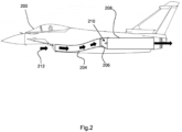
- FIG. 2 shows example of a schematic diagram of an engine duct 204 in an aircraft 200 comprising the airflow modifying device 206 according to the invention.
- the aircraft comprises an internal engine 208 with an engine face 210 housed within the super structure of the aircraft 200.
- the engine duct 204 comprises an inlet towards the front of the aircraft for directing air internally within the aircraft 200 superstructure to the engine face 210.
- the incident airflow 212 is a fluid in a substantially laminar flow. As the incident airflow 212 enters the engine duct 204, turbulence is caused such that the cross sectional flow at any point in the engine duct 204 is circumferentially asymmetric.
- a airflow modifying device 206 is provided immediately preceding the engine face 210.
- the airflow modifying device 206 comprises a geometry which is configured to modulate the flow.
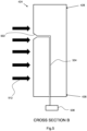
- Figure 3 shows the engine duct of Figure 2 in more detail.
- incident airflow 212 enters the engine duct 204, the flow transitions from a substantially laminar flow to a turbulent flow as indicated by flow arrows 214.
- the turbulent airflow passes through the inlet of the airflow modifying device, the flow is modulated and restored to an at least partially laminar flow at the engine face 210.
- Figures 4a & 4b show an example of a spoke design airflow modifying device 406.
- Figure 4a shows a side view of the airflow modifying device 406
- Figure 4b shows a cross sectional diagram along axis-A of Figure 4a .
- the airflow modifying device 406 comprises a flow inlet 416, a flow outlet 418 and a flow passage 420 extending from the flow inlet 416 to the flow outlet 418.
- the airflow modifying device 406 comprises a core hub 422 and eight blades 424 radially extending from the core hub 422 in an equiangular arrangement.
- Each blade 424 comprise a blade root 426 located proximal to the core hub 422 and the blade tip 428 at the distal end of each blade 424.
- the blade tips 428 of each of the blades 424 are enclosed by a housing 430.
- the core hub 422, blades 424 and housing 430 are a made from a single body produced for example by additive manufacture although in an alternative arrangement, they may be made from discreet components joined mechanically, chemically or comprising a joining geometry to enable an interference fit.
- one of the blades 425 comprises an integral pitot sensor 402, which may be more clearly seen in Figure 5 .
- FIG. 5 shows a cross sectional view along axis B of the blade 424 of Figure 4b .
- the blade 424 comprising the pitot sensor 502 integral with the blade 424 of the airflow modifying device.
- the pitot sensor 502 comprises a bell mouth orifice.
- a pressure line 534 connected to the pitot sensor 502 at a first end and connected to a transducer 536 at a second end.
- the pressure line 534 is completely enclosed within the blade 424 of the airflow modifying device between the first and second ends. In use, incident airflow enters the pitot sensor 502 and comes to rest within the pressure line 534.
- the transducer 536 is configured to measure the stagnant pressure within the pressure line 534 which may then be used to infer an airspeed of the incident air 512.
- the transducer 536 is shown as external to the blade 424 proximal to the blade root 426, the transducer 536 may alternatively be located within the blade 424.
- FIG 6 shows an alternative arrangement of an airflow modifying device 606 according to the invention.
- the airflow modifying device 606 is as shown in Figure 4 (406) however, instead of a core hub 422 and blades 424, the airflow modifying device 606 comprises a honeycomb design comprising a plurality of hexagonal cells 638, each cell separated by a cell wall 640.
- the cells 638 are bounded by a housing 630 as in Figure 4 .
- the pitot sensors 602 are formed within the cell walls 640 (not to scale).
- Each pitot sensor 602 comprises a respective pressure line (not shown) completely enclosed within the cell walls 640.
Landscapes
- Engineering & Computer Science (AREA)
- Aviation & Aerospace Engineering (AREA)
- Physics & Mathematics (AREA)
- General Physics & Mathematics (AREA)
- Chemical & Material Sciences (AREA)
- Combustion & Propulsion (AREA)
- Measuring Fluid Pressure (AREA)
Priority Applications (3)
| Application Number | Priority Date | Filing Date | Title |
|---|---|---|---|
| EP23275073.7A EP4458679A1 (de) | 2023-05-03 | 2023-05-03 | Luftstrommodifizierungsvorrichtung |
| EP24724603.6A EP4705185A1 (de) | 2023-05-03 | 2024-04-29 | Luftstrommodifizierungsvorrichtung |
| PCT/GB2024/051129 WO2024228011A1 (en) | 2023-05-03 | 2024-04-29 | Airflow modifying device |
Applications Claiming Priority (1)
| Application Number | Priority Date | Filing Date | Title |
|---|---|---|---|
| EP23275073.7A EP4458679A1 (de) | 2023-05-03 | 2023-05-03 | Luftstrommodifizierungsvorrichtung |
Publications (1)
| Publication Number | Publication Date |
|---|---|
| EP4458679A1 true EP4458679A1 (de) | 2024-11-06 |
Family
ID=86329863
Family Applications (1)
| Application Number | Title | Priority Date | Filing Date |
|---|---|---|---|
| EP23275073.7A Ceased EP4458679A1 (de) | 2023-05-03 | 2023-05-03 | Luftstrommodifizierungsvorrichtung |
Country Status (1)
| Country | Link |
|---|---|
| EP (1) | EP4458679A1 (de) |
Citations (4)
| Publication number | Priority date | Publication date | Assignee | Title |
|---|---|---|---|---|
| GB801746A (en) * | 1955-10-10 | 1958-09-17 | Leonard Philman Leigh | Control device for deicing apparatus for aircraft |
| US20160348531A1 (en) * | 2014-02-05 | 2016-12-01 | United Technologies Corporation | Integral instrumentation in additively manufactured components of gas turbine engines |
| US20170284304A1 (en) * | 2016-03-30 | 2017-10-05 | General Electric Company | Valved airflow passage assembly for adjusting airflow distortion in gas turbine engine |
| US20210270144A1 (en) * | 2020-02-28 | 2021-09-02 | Rosemount Aerospace Inc. | Pressure and temperature sensors and related methods |
-
2023
- 2023-05-03 EP EP23275073.7A patent/EP4458679A1/de not_active Ceased
Patent Citations (4)
| Publication number | Priority date | Publication date | Assignee | Title |
|---|---|---|---|---|
| GB801746A (en) * | 1955-10-10 | 1958-09-17 | Leonard Philman Leigh | Control device for deicing apparatus for aircraft |
| US20160348531A1 (en) * | 2014-02-05 | 2016-12-01 | United Technologies Corporation | Integral instrumentation in additively manufactured components of gas turbine engines |
| US20170284304A1 (en) * | 2016-03-30 | 2017-10-05 | General Electric Company | Valved airflow passage assembly for adjusting airflow distortion in gas turbine engine |
| US20210270144A1 (en) * | 2020-02-28 | 2021-09-02 | Rosemount Aerospace Inc. | Pressure and temperature sensors and related methods |
Similar Documents
| Publication | Publication Date | Title |
|---|---|---|
| EP0719416B1 (de) | Integrierbarer tragflächenmessaufnehmer für die gesamttemperatur | |
| US11731782B2 (en) | Bulkheads for air data probes | |
| EP2700952B1 (de) | Feuchtigkeitsbeständige Luftdatensonden | |
| EP2290344A1 (de) | Verbesserte aspirierte Gesamtlufttemperatursonde | |
| EP2848904B1 (de) | Überkritische Gesamtlufttemperatursensoren | |
| US6840672B2 (en) | Total air temperature probe providing improved anti-icing performance and reduced deicing heater error | |
| EP2863195B1 (de) | Gesamtlufttemperatursensoren | |
| US6490510B1 (en) | Fixed multifunction probe for aircraft | |
| EP3546907B1 (de) | Selbstregelndes heizsystem für eine gesamtlufttemperatursonde | |
| EP3399291B1 (de) | Vereisungswiderstandgesamttemperatursonde mit integriertem ausstosser | |
| EP0287223B1 (de) | Vorrichtung zum Messen von Luftdaten | |
| EP3205582B1 (de) | Gesamtlufttemperatursonde mit effizientem teilchendurchgang | |
| US20180143082A1 (en) | Systems and methods for icing resistant total air temperature probes | |
| JP2005522700A (ja) | 風角度計測用センサ | |
| EP4458679A1 (de) | Luftstrommodifizierungsvorrichtung | |
| GB2629594A (en) | Airflow modifying device | |
| WO2024228011A1 (en) | Airflow modifying device | |
| Vogeley | Langley Aeronautical Laboratory |
Legal Events
| Date | Code | Title | Description |
|---|---|---|---|
| PUAI | Public reference made under article 153(3) epc to a published international application that has entered the european phase |
Free format text: ORIGINAL CODE: 0009012 |
|
| STAA | Information on the status of an ep patent application or granted ep patent |
Free format text: STATUS: THE APPLICATION HAS BEEN PUBLISHED |
|
| AK | Designated contracting states |
Kind code of ref document: A1 Designated state(s): AL AT BE BG CH CY CZ DE DK EE ES FI FR GB GR HR HU IE IS IT LI LT LU LV MC ME MK MT NL NO PL PT RO RS SE SI SK SM TR |
|
| STAA | Information on the status of an ep patent application or granted ep patent |
Free format text: STATUS: THE APPLICATION HAS BEEN REFUSED |
|
| 18R | Application refused |
Effective date: 20250121 |