EP4458668A2 - Verteilte fahrwerkssystemarchitektur für elektromechanische betätigung - Google Patents
Verteilte fahrwerkssystemarchitektur für elektromechanische betätigung Download PDFInfo
- Publication number
- EP4458668A2 EP4458668A2 EP24201773.9A EP24201773A EP4458668A2 EP 4458668 A2 EP4458668 A2 EP 4458668A2 EP 24201773 A EP24201773 A EP 24201773A EP 4458668 A2 EP4458668 A2 EP 4458668A2
- Authority
- EP
- European Patent Office
- Prior art keywords
- motor
- controller
- drive unit
- gear
- motor drive
- Prior art date
- Legal status (The legal status is an assumption and is not a legal conclusion. Google has not performed a legal analysis and makes no representation as to the accuracy of the status listed.)
- Withdrawn
Links
Images


Classifications
-
- B—PERFORMING OPERATIONS; TRANSPORTING
- B64—AIRCRAFT; AVIATION; COSMONAUTICS
- B64C—AEROPLANES; HELICOPTERS
- B64C25/00—Alighting gear
- B64C25/02—Undercarriages
- B64C25/08—Undercarriages non-fixed, e.g. jettisonable
- B64C25/10—Undercarriages non-fixed, e.g. jettisonable retractable, foldable, or the like
- B64C25/18—Operating mechanisms
- B64C25/24—Operating mechanisms electric
-
- B—PERFORMING OPERATIONS; TRANSPORTING
- B64—AIRCRAFT; AVIATION; COSMONAUTICS
- B64C—AEROPLANES; HELICOPTERS
- B64C25/00—Alighting gear
- B64C25/02—Undercarriages
- B64C25/08—Undercarriages non-fixed, e.g. jettisonable
- B64C25/10—Undercarriages non-fixed, e.g. jettisonable retractable, foldable, or the like
-
- B—PERFORMING OPERATIONS; TRANSPORTING
- B64—AIRCRAFT; AVIATION; COSMONAUTICS
- B64C—AEROPLANES; HELICOPTERS
- B64C25/00—Alighting gear
- B64C25/02—Undercarriages
- B64C25/08—Undercarriages non-fixed, e.g. jettisonable
- B64C25/10—Undercarriages non-fixed, e.g. jettisonable retractable, foldable, or the like
- B64C25/18—Operating mechanisms
- B64C25/26—Control or locking systems therefor
-
- B—PERFORMING OPERATIONS; TRANSPORTING
- B64—AIRCRAFT; AVIATION; COSMONAUTICS
- B64C—AEROPLANES; HELICOPTERS
- B64C25/00—Alighting gear
- B64C25/02—Undercarriages
- B64C25/08—Undercarriages non-fixed, e.g. jettisonable
- B64C25/10—Undercarriages non-fixed, e.g. jettisonable retractable, foldable, or the like
- B64C25/16—Fairings movable in conjunction with undercarriage elements
-
- B—PERFORMING OPERATIONS; TRANSPORTING
- B64—AIRCRAFT; AVIATION; COSMONAUTICS
- B64C—AEROPLANES; HELICOPTERS
- B64C25/00—Alighting gear
- B64C25/32—Alighting gear characterised by elements which contact the ground or similar surface
- B64C25/42—Arrangement or adaptation of brakes
Definitions
- the present disclosure relates to landing gear, and more particularly, to distributed landing gear system architectures for controlling actuation of landing gear subsystems.
- Aircrafts generally include landing gear that supports the aircraft during taxi, take-off, and landing. After take-off, the landing gear may be translated to a "landing gear up" position, wherein the landing gear translates into a wheel well defined by, for example, a wing or a fuselage of the aircraft.
- Electrical landing gear systems may include electromechanical actuators (EMAs), or electric motors, configured to actuate various landing gear subsystems.
- EMA electromechanical actuators
- Each EMA may have dedicated controller and motor drive unit configured to control and power the EMA.
- a controller and motor drive unit for each EMA tends to increase the size, weight, and number of parts associated with electrical landing gear systems.
- Systems for controlling landing gear are disclosed in US 2013/082149 , US 2018/370619 and US 2014/100719 .
- a landing gear system is disclosed herein.
- the landing gear system comprises a nose gear door motor and a nose gear motor drive unit in operable communication with the nose gear door motor.
- a nose gear retraction-extension motor is in operable communication with the nose gear motor drive unit.
- An alternating current direct current converter is electrically coupled to the nose gear motor drive unit.
- a controller is in operable communication with the nose gear motor drive unit.
- a tangible, non-transitory memory is configured to communicate with the controller.
- the tangible, non-transitory memory has instructions stored thereon that, in response to execution by the controller, cause the controller to perform operations, which comprise receiving, by the controller, a pilot command; determining, by the controller, a nose landing gear power sequence for providing powering to the nose gear door motor and the nose gear retraction-extension motor in response to receiving the pilot command; and outputting, by the controller, a first command to the nose gear motor drive unit.
- the nose gear motor drive unit is configured to power either the nose gear door motor or the nose gear retraction-extension motor based on the first command from the controller.
- the nose gear motor drive unit may include a programmable logic device configured to receive commands, including the first command, from the controller.
- the programmable logic device may generate pulse width modulation signals configured to control at least one of the nose gear door motor or the nose gear retraction-extension motor based on the commands received from the controller.
- a first sensor may be operably coupled to the nose gear door motor and in communication with the controller.
- a second sensor may be operably coupled to the nose gear retraction-extension motor and in communication with the controller.
- the operations may further comprise receiving, by the controller, a first signal from the first sensor; and determining, by the controller, whether to power the nose gear door motor or the nose gear retraction-extension motor based on the first signal.
- a main gear motor drive unit may be electrically coupled to the alternating current direct current converter and in operable communication with the controller.
- a main gear door motor may be in operable communication with the main gear motor drive unit.
- a brake control motor may be in operable communication with the main gear motor drive unit.
- the operations may further comprise determining, by the controller, a main landing gear power sequence for powering the main gear door motor and the brake control motor in response to receiving the pilot command; and outputting, by the controller, a second command to the main gear motor drive unit.
- the main gear motor drive unit may be configured to power either the main gear door motor or the brake control motor based on the second command from the controller.
- a system for controlling landing gear subsystems comprises a controller and a first motor drive unit in operable communication with the controller.
- a first electric motor and a second electric motor are in operable communication with the first motor drive unit.
- a second motor drive unit is in operable communication with the controller.
- a third electric motor and a fourth electric motor are in operable communication with the second motor drive unit.
- An alternating current direct current converter is electrically coupled to the first motor drive unit and the second motor drive unit.
- a braking resistor may be electrically coupled to the first motor drive unit and the second motor drive unit.
- the first motor drive unit may include a first programmable logic device configured to receive a first command from the controller and generate first pulse width modulation signals configured to control at least one of the first electric motor or the second electric motor in response to the first command from the controller.
- the second motor drive unit may include a second programmable logic device configured to receive a second command from the controller and generate second pulse width modulation signals configured to control at least one of the third electric motor or the fourth electric motor in response to the second command from the controller.
- a first sensor may be operably coupled to the first electric motor and in communication with the controller.
- a second sensor may be operably coupled to the second electric motor and in communication with the controller.
- a third sensor may be operably coupled to the third electric motor and in communication with the controller.
- a fourth sensor may be operably coupled to the fourth electric motor and in communication with the controller.
- the first motor drive unit may be configured to drive the first electric motor non-simultaneously with the second electric motor.
- the second motor drive unit may be configured to drive the third electric motor non-simultaneously with the fourth electric motor at a time.
- the first electric motor may be configured to actuate a nose landing gear bay door
- the second electric motor may be configured to actuate a nose landing gear between a landing gear up position and a landing gear down position, s
- any reference to singular includes plural embodiments, and any reference to more than one component or step may include a singular embodiment or step.
- any reference to attached, fixed, connected or the like may include permanent, removable, temporary, partial, full, and/or any other possible attachment option.
- any reference to without contact (or similar phrases) may also include reduced contact or minimal contact.
- Surface cross hatching lines may be used throughout the figures to denote different parts but not necessarily to denote the same or different materials.
- the system may include a common controller, AC/DC converter, and braking resistor operationally coupled to multiple motor drive units.
- electric motors having non simultaneous operational times may be driven by a common (i.e., shared) motor drive unit.
- the disclosed systems may reduce costs and weight as compared to systems having a motor drive unit for each motor and a controller, AC/DC converter, and braking resistor for each motor drive unit.
- System program instructions and/or controller instructions may be loaded onto a tangible, non-transitory, computer-readable medium (also referred to herein as a tangible, non-transitory, memory) having instructions stored thereon that, in response to execution by a controller, cause the controller to perform various operations.
- a tangible, non-transitory, computer-readable medium also referred to herein as a tangible, non-transitory, memory
- the term "non-transitory” is to be understood to remove only propagating transitory signals per se from the claim scope and does not relinquish rights to all standard computer-readable media that are not only propagating transitory signals per se.
- Aircraft 10 may include a fuselage 11 and wings 13. Aircraft 10 may further include landing gear such as left landing gear 12, right landing gear 14, and nose landing gear 16. Left landing gear 12, right landing gear 14, and nose landing gear 16 may generally support aircraft 10, when aircraft 10 is not flying, allowing aircraft 10 to taxi, take-off, and land without damage. Nose landing gear 16 is located under the nose of aircraft 10 and may not include a brake assembly. Nose landing gear 16 may be generally used for steering aircraft 10 during taxiing. Left landing gear 12 and right landing gear 14 may differ from nose landing gear 16, in that left landing gear 12 and right landing gear 14 each generally include a brake assembly.
- landing gear 12 and right landing gear 14 may differ from nose landing gear 16, in that left landing gear 12 and right landing gear 14 each generally include a brake assembly.
- Left landing gear 12, right landing gear 14, and nose landing gear 16 may each include various shock strut assemblies with one or more wheels attached thereto.
- Left landing gear 12, right landing gear 14, and nose landing gear 16 may each be configured to translate between a landing gear down position, wherein the landing gear extend from wings 13 and/or from fuselage 11 to support aircraft 10, and a landing gear up position, wherein the landing gear are located within wings 13 and/or fuselage 11 of aircraft 10.
- left landing gear 12, right landing gear 14, and nose landing gear 16 may be in the landing gear down position.
- left landing gear 12, right landing gear 14, and nose landing gear 16 may be translated to the landing gear up position.
- Prior to landing, left landing gear 12, right landing gear 14, and nose landing gear 16 may be translated to the landing gear down position to support aircraft 10 during landing.
- aircraft 10 may comprise any number of landing gears and each landing gear may comprise any number of wheels.
- aircraft 10 may include main landing gear bay doors 20 and nose landing gear bay doors 22, which may be translated between an open position prior to landing gear retraction to a closed position after landing gear retraction.
- Bay doors 20, 22 are also translated to the open position prior to landing gear extension.
- aircraft 10 may include a landing gear system 100 configured to control operation of left landing gear 12 and right landing gear 14 (collectively referred to as "main landing gear") and operation of nose landing gear 16.
- landing gear system 100 comprises various subsystems configured to control different aspects of landing gear operation.
- landing gear system 100 includes a nose landing gear bay door actuation subsystem 102 for controlling the opening and closing of nose landing gear bay doors 22, a nose landing gear retraction-extension subsystem 104 for controlling retraction and extension of nose landing gear 16, a nose landing gear steering subsystem 106 for controlling steering of nose landing gear 16, and a nose landing gear emergency extension subsystem 108 for extending nose landing gear 16 should the nose landing gear retraction-extension subsystem 104 fail.
- Landing gear system 100 may further include a main gear bay door actuation subsystem 110 for controlling the opening and closing of main landing gear bay doors 20, a main landing gear retraction-extension subsystem 112 for controlling retraction and extension of main landing gear 12, 14, a main landing gear brake control subsystem 114 for controlling the brake assemblies of main landing gear 12, 14, and a main landing gear emergency extension subsystem 116 for extending main landing gear 12, 14 should the main landing gear retraction-extension subsystem 112 fail.
- a main gear bay door actuation subsystem 110 for controlling the opening and closing of main landing gear bay doors 20
- a main landing gear retraction-extension subsystem 112 for controlling retraction and extension of main landing gear 12, 14
- a main landing gear brake control subsystem 114 for controlling the brake assemblies of main landing gear 12, 14, and a main landing gear emergency extension subsystem 116 for extending main landing gear 12, 14 should the main landing gear retraction-extension subsystem 112 fail.
- the subsystems of landing gear system 100 generally do not operate simultaneously.
- TABLE 1 shows a typical operational scenario of aircraft 10, where T1, T2, and T3 are the time durations for operation of landing gear subsystems 102, 104, 106, 110, 112, 114, and Power Demand is the relative power (e.g., high or low) associated with operation of the respective subsystem.
- nose landing gear door actuation, nose landing gear retraction-extension, and nose landing gear steering control do not have overlapping operation time.
- main landing gear door actuation, main landing gear retraction-extension, and main landing gear brake control have non-simultaneous (i.e., nonconcurrent) operation.
- landing gear system 100 may be a hybrid system that employs electromechanical actuators, or electric motors, for actuation of landing gear subsystems 102, 104, 106, 110, and 114, and hydraulic actuators for actuation of main landing gear retraction-extension subsystem 112.
- landing gear system 100 may employ electromechanical actuators, or electric motors, for actuation of landing gear subsystems 102, 104, 106, 110, and 114, and for actuation of main landing gear retraction-extension subsystem 112.
- System 120 may include a nose gear door actuation, gear retraction-extension, and emergency extension motor drive unit 130 (referred to herein as nose gear motor drive unit 130) configured to drive a nose gear door motor 132, a nose gear retraction-extension motor 134, and an emergency nose gear extension motor 136.
- nose gear door motor 132, nose gear retraction-extension motor 134, and emergency nose gear extension motor 136 may each comprises an electric motor (e.g., a permanent magnet synchronous motor (PMSM), a brushless direct current (BLDC) motor, or other suitable electric motor).
- PMSM permanent magnet synchronous motor
- BLDC brushless direct current
- Nose gear door motor 132 may translate nose landing gear bay doors 22 between the open and closed position.
- Nose gear retraction-extension motor 134 may translate nose landing gear 16 between the landing gear down and landing gear up positions.
- Emergency nose gear extension motor 136 may translate nose landing gear 16 to the landing gear down position.
- nose gear door motor 132 nose gear retraction-extension motor 134
- emergency nose gear extension motor 136 may be operated at different times (i.e., not simultaneously).
- a single nose gear motor drive unit 130 may be employed to operate (i.e., drive) nose gear door motor 132, nose gear retraction-extension motor 134, and emergency nose gear extension motor 136.
- nose gear motor drive unit 130 is driving nose gear door motor 132
- nose gear retraction-extension motor 134, and emergency nose gear extension motor 136 may be dormant (i.e., powered off).
- System 120 may further include a steering motor drive unit 140 configured to drive steering control motor 142.
- steering control motor 142 comprises an electric motor (e.g., a PMSM, a BLDC motor, or other suitable electric motor).
- Steering control motor 142 may control the steering system used to steer nose landing gear 16 (e.g., steering control motor 142 may pivot, or turn, nose landing gear 16 to the left or to the right).
- steering control motor 142 may be operated at a different time from (i.e., non-simultaneously or nonconcurrent with) nose gear door motor 132, nose gear retraction-extension motor 134, and emergency nose gear extension motor 136.
- System 120 may further include a main landing gear door actuation and brake control motor drive unit 150 (referred to herein as main gear motor drive unit 150) configured to drive one or more main gear door motor(s) 152 and one or more brake control motor(s) 154.
- main gear door motors 152 and brake control motors 154 comprise electric motors (e.g. PMSMs, BLDC motors, or other suitable electric motor).
- Main gear door motors 152 translate main landing gear bay doors 20 between the open and closed positions.
- Brake control motors 154 control the braking of main landing gear 12, 14.
- brake control motors 154 may control the braking pressure applied by the brake assemblies of main landing gear 12, 14.
- main gear door motors 152 and brake control motors 154 may be operated at different times (i.e., non-simultaneously or nonconcurrent with one another).
- a single main gear motor drive unit 150 may be employed to operate (i.e., drive) main gear door motors 152 and brake control motors 154.
- the brake control motors 154 may be dormant (i.e., powered off).
- System 120 further includes a controller 122.
- Controller 122 is operably coupled to and in communication with nose gear motor drive unit 130, steering motor drive unit 140, and main gear motor drive unit 150.
- Controller 122 may include operating instructions and/or power sequence logic configured to cause nose gear motor drive unit 130, steering motor drive unit 140, and/or main gear motor drive unit 150 to power motors 132, 134, 136, 142, 152, and 154 in a particular order and/or during certain operating conditions.
- Controller 122 may include and communicate with one or more processors and one or more tangible, non-transitory storage medium(s), or memories, 124 and is capable of implementing landing gear logic.
- the processor can be a general purpose processor, a digital signal processor (DSP), an application specific integrated circuit (ASIC), a field programmable gate array (FPGA) or other programmable logic device (PLD), discrete gate or transistor logic, discrete hardware components, or a combination thereof.
- System program instructions and/or processor instructions may be loaded onto tangible, non-transitory computer-readable storage medium 124. The system program instructions and/or processor instructions may, in response to execution by controller 122, cause controller 122 to perform various operations.
- the instructions may allow controller 122 to make operating and/or power sequence decisions relative the landing gear subsystems.
- controller 122 may be configured to determine which of motors 132, 134, 136, 142, 152, 154 should be receiving power and/or operating at a particular time.
- system 120 may include one or more door sensors 180 operationally coupled to nose gear door motor 132 and/or to nose landing gear bay doors 22.
- the output of door sensors 180 may correlate to operating conditions of nose gear door motor 132 (e.g., velocity, position, etc.).
- the output of door sensors 180 may also provide information related to the position of nose landing gear bay doors 22.
- the output of door sensors 180 may be received by nose gear motor drive unit 130.
- the output of door sensors 180 may be sent from nose gear motor drive unit 130 to controller 122. Controller 122 may make decisions related to the operation of nose gear door motor 132 based on the signals output from door sensors 180.
- Controller 122 may also make decisions related to the operation of nose gear retraction-extension motor 134, emergency nose gear extension motor 136 and/or steering control motor 142 based on the signals output from door sensors 180.
- controller 122 may output commands to nose gear motor drive unit 130 configured to cause nose gear motor drive unit 130 to power (or excite) door sensors 180, when nose gear door motor 132 is in operation.
- door sensors 180 may also operate (i.e., receive power and provide output) when nose gear door motor 132 is turned off.
- System 120 may include one or more retraction sensors 182 operationally coupled to nose gear retraction-extension motor 134 and/or to components of nose landing gear 16 (e.g., to a shock struct of nose landing gear 16).
- the output of retraction sensors 182 may correlate to one or more operating conditions of nose gear retraction-extension motor 134 (e.g., velocity, position, etc.).
- the output of retraction sensors 182 may also provide information related to the position of nose landing gear 16 (e.g., extended, retracted, etc.).
- the output of retraction sensors 182 may be received by nose gear motor drive unit 130.
- the output of retraction sensors 182 may be sent from nose gear motor drive unit 130 to controller 122.
- Controller 122 may make decisions related to the operation of nose gear retraction-extension motor 134 based on the signals output from retraction sensors 182. Controller 122 may also make decisions related to the operation of nose gear door motor 132, emergency nose gear extension motor 136 and/or steering control motor 142 based on the signals output from retraction sensors 182. In various embodiments, controller 122 may output commands to nose gear motor drive unit 130 configured to cause nose gear motor drive unit 130 to power (or excite) retraction sensors 182, when nose gear retraction-extension motor 134 is in operation. In various embodiments, retraction sensors 182 may also operate (i.e., receive power and provide output) when nose gear retraction-extension motor 134 is turned off.
- System 120 may include one or more emergency extension sensors 184 operationally coupled to emergency nose gear extension motor 136 and/or to components of nose landing gear 16 (e.g., to a shock struct of nose landing gear 16).
- the output of emergency extension sensors 184 may correlate to operating conditions of emergency nose gear extension motor 136 (e.g., velocity, position, etc.).
- the output of emergency extension sensors 184 may also provide information related to the position of nose landing gear 16 (e.g., extended, retracted, etc.).
- the output of emergency extension sensors 184 may be received by nose gear motor drive unit 130.
- the output of emergency extension sensors 184 may be sent from nose gear motor drive unit 130 to controller 122.
- Controller 122 may make decisions related to the operation of emergency nose gear extension motor 136 based on the signals output from emergency extension sensors 184. Controller 122 may also make decision related to the operation of nose gear door motor 132, nose gear retraction-extension motor 134, and/or steering control motor 142 based on the signals output from emergency extension sensors 184. In various embodiments, controller 122 may output commands to nose gear motor drive unit 130 configured to cause nose gear motor drive unit 130 to power (or excite) emergency extension sensors 184, when emergency nose gear extension motor 136 is in operation. In various embodiments, emergency extension sensors 184 may also operate (i.e., receive power and provide output) when emergency nose gear extension motor 136 is turned off.
- System 120 may include one or more steering sensors 186 operationally coupled to steering control motor 142 and/or to components of nose landing gear 16.
- the output from steering sensors 186 may correlate to one or more operating conditions of steering control motor 142 (e.g., velocity, position, etc.).
- the output of steering sensors 186 may also provide information related to the positioning or orientation (left, right, etc.) of nose landing gear 16.
- the output of steering sensors 186 may be received by steering motor drive unit 140.
- the output from steering sensors 186 may be sent from steering motor drive unit 140 to controller 122. Controller 122 may make decisions related to the operation of steering control motor 142 based on the signals output from steering sensors 186.
- Controller 122 may also make decisions related to the operation of nose gear door motor 132, nose gear retraction-extension motor 134, and/or emergency nose gear extension motor 136 based on the signals output from steering sensors 186.
- controller 122 may output commands to steering motor drive unit 140 configured to cause steering motor drive unit 140 to power (or excite) steering sensors 186, when steering control motor 142 is in operation.
- steering sensors 186 may also operate (i.e., receive power and provide output), when steering control motor 142 is turned off.
- System 120 may include one or more main door sensors 188 operationally coupled to main gear door motors 152 and/or to main landing gear bay doors 20.
- the output of main door sensors 188 may correlate to one or more operating conditions of main gear door motors 152 (e.g., velocity, position, etc.).
- the output of main door sensors 188 may also provide information related to the position of main landing gear bay doors 20.
- the output of main door sensors 188 may be received by main gear motor drive unit 150.
- the output of main door sensors 188 may be sent from main gear motor drive unit 150 to controller 122. Controller 122 may make decisions related to the operation of main gear door motors 152 based on the signals output from main door sensors 188.
- controller 122 may also make decisions related to the operation of brake control motors 154 based on the output from main door sensors 188.
- controller 122 may output commands to main gear motor drive unit 150 configured to cause main gear motor drive unit 150 to power (or excite) main door sensors 188, when main gear door motors 152 is in operation.
- main door sensors 188 may also operate (i.e., receive power and provide output), when main gear door motors 152 are turned off.
- System 120 may include one or more brake sensors 190 operationally coupled to the brake control motors 154 and/or to the braking assemblies or other components of the main landing gear 12, 14.
- the brake sensors 190 may include sensor that output data correlating to one or more operating conditions of the brake control motors 154 (e.g., velocity, position, etc.).
- Brake sensors 190 may also include sensor configured to out information related to the position or pressure being applied by the brake assemblies of the main landing gear 12, 14.
- Brake sensors 190 may also include sensors that provide information related to whether aircraft 10 is on the ground or in the air (e.g., brake sensors 190 may include one or more weight on wheels sensors).
- the brake assemblies of main landing gear 12, 14 may be configured to not apply braking pressure when the aircraft is in the air (e.g., brake command signals from the pilot or from an autobraking system may be disabled when the aircraft is in the air).
- the brake assemblies may be configured to apply braking pressure when, based on the output from one or more brake sensors 190, aircraft 10 is determined to be on the ground.
- the output of brake sensors 190 may be received by main gear motor drive unit 150.
- the output of brake sensors 190 may be sent from main gear motor drive unit 150 to controller 122. Controller 122 may make decisions related to the operation of brake control motors 154 based on the signals output from brake sensors 190.
- Controller 122 may also make decisions related to the operation of main gear door motors 152 based on the signals output from brake sensors 190.
- controller 122 may output commands to main gear motor drive unit 150 configured to cause main gear motor drive unit 150 to power (or excite) brake sensors 190, when brake control motors 154 are in operation.
- brake sensors 190 may also operate (i.e., receive power and provide output), when brake control motors 154 are turned off.
- controller 122 is configured to make operating decisions for controlling the various landing gear subsystems and motors 132, 134, 136, 142, 152, 154. Controller 122 may determine the sequence in which motors 132, 134, 136, 142, 152, 154 are powered in response to receiving pilot commands 126 from the cockpit (e.g., from the pilot, the co-pilot, or higher level flight control systems) of aircraft 10. Stated differently, controller 122 may determine a nose gear power sequence for powering motors 132, 134, 136, and 142 and a main landing gear power sequence for powering main gear door motors 152 and brake control motors 154 in response to receiving pilot command 126.
- pilot commands 126 from the cockpit (e.g., from the pilot, the co-pilot, or higher level flight control systems) of aircraft 10. Stated differently, controller 122 may determine a nose gear power sequence for powering motors 132, 134, 136, and 142 and a main landing gear power sequence for powering main gear door motors
- controller 122 may receive pilot command 126 in response to, for example, the pilot translating a landing gear lever 128 between a landing up lever position and a landing gear down lever position. Controller 122 may determine a sequence of operation for motors 132, 134, 136, 142, 152, 154 in response to pilot command 126. Stated differently, controller 122 may output a series of power commands to nose gear motor drive unit 130, steering motor drive unit 140, and/or main gear motor drive unit 150, in response to the landing gear lever 128 being translated from the landing up lever position to the landing down lever position or from the landing gear down lever position to the landing gear up lever position.
- controller 122 may determine a nose gear power sequence configured to first open the nose landing gear bay doors 22, then extend the nose landing gear 16, and then power the steering motor.
- controller 122 may be configured to, in response to receiving pilot command 126, output a command (or series of commands) to nose gear motor drive unit 130.
- the command may be configured to cause nose gear motor drive unit 130 to power nose gear door motor 132, thereby causing nose landing gear bay doors 22 to open.
- controller 122 may send a command (or series of commands) to nose gear motor drive unit 130 configured to cause nose gear motor drive unit 130 to stop powering (i.e., power-off) nose gear door motor 132 and to start powering (i.e., power-on) nose gear retraction-extension motor 134, thereby causing nose landing gear 16 to extend.
- a command or series of commands
- controller 122 may send a command (or series of commands) configured to cause nose gear motor drive unit 130 to stop powering (i.e., power-off) nose gear retraction-extension motor 134 and to start powering (i.e., power-on), emergency nose gear extension motor 136, thereby causing nose landing gear 16 to extend.
- controller 122 may send a command (or series of commands) to steering motor drive unit 140 and a command (or series of commands) to nose gear motor drive unit 130.
- the commands may be configured to cause nose gear motor drive unit 130 to stop powering (i.e., power-off) nose gear retraction-extension motor 134 and to start powering (i.e., power-on) steering control motor 142.
- controller 122 may also determine a main landing gear power sequence configured to first power the main gear door motors 152 and then power the brake control motors 154.
- controller 122 may be configured to, in response to receiving pilot command 126, output a first command (or series of first commands) to main gear motor drive unit 150 configured to cause main gear motor drive unit 150 to power the main gear door motors 152, thereby causing main landing gear bay doors 20 to open.
- controller 122 may send a command (or series of second commands) to main gear motor drive unit 150 configured to cause main gear motor drive unit 150 to stop powering (i.e., power-off) main gear door motors 152 and to start powering (i.e., power-on) brake control motors 154.
- system 120 includes an alternating current to direct current (AC/DC) converter 200.
- AC/DC converter 200 is configured to provide power (e.g., DC current) to each of nose gear motor drive unit 130, steering motor drive unit 140, and main gear motor drive unit 150.
- AC/DC converter 200 is electrically coupled to an AC power supply 202 and to nose gear motor drive unit 130, steering motor drive unit 140, and main gear motor drive unit 150.
- AC/DC converter 200 is configured convert the AC received from AC power supply 202 to DC, which is provided to nose gear motor drive unit 130, steering motor drive unit 140, and/or main gear motor drive unit 150.
- the power provided by AC/DC converter 200 is configured to power nose gear door motor 132, nose gear retraction-extension motor 134, emergency nose gear extension motor 136, steering control motor 142, main gear door motors 152, and/or brake control motors 154.
- Power may be provided by a common, or single, AC/DC converter 200 as drive nose gear door motor 132, nose gear retraction-extension motor 134, and emergency nose gear extension motor 136 do not operate simultaneously and because main gear door motors 152 do not operate simultaneously with brake control motors 154.
- the current provided by AC/DC converter 200 may be supplied to either nose gear door motor 132, nose gear retraction-extension motor 134, or emergency nose gear extension motor 136; to steering control motor 142; and to either main gear door motors 152 or brake control motors 154.
- controller 122 may determine the sequence in which power from AC/DC converter 200 is provided to nose gear door motor 132, nose gear retraction-extension motor 134, emergency nose gear extension motor 136, and steering control motor 142 and the sequence in which power from AC/DC converter 200 is provided to main gear door motors 152 and brake control motors 154.
- pilot command 126 e.g., a landing gear lever up or landing gear lever down signal
- controller 122 determines and controls which nose landing gear motors (e.g., nose gear door motor 132, nose gear retraction-extension motor 134, emergency nose gear extension motor 136, or steering control motor 142) and which main landing gear motors (e.g., main gear door motors 152 or brake control motors 154) should be powered-on and which should be powered-off. Controller 122 may send commands to nose gear motor drive unit 130, steering motor drive unit 140, and main gear motor drive unit 150 based on the determined sequence. The commands are configured to cause to nose gear motor drive unit 130, steering motor drive unit 140, main gear motor drive unit 150 to power the motor(s) in the sequence determined by controller 122.
- nose landing gear motors e.g., nose gear door motor 132, nose gear retraction-extension motor 134, emergency nose gear extension motor 136, or steering control motor 14
- main landing gear motors e.g., main gear door motors 152 or brake control motors 15
- System 120 employs a centralized AC/DC converter 200, rather than individual AC/DC converter for each drive unit.
- the power provided by AC/DC converter 200 may be less than the sum of the peak of the power associated with driving each of motors 132, 134, 136, 142, 152, 154, as motors 132, 134, and 136, for example, do not operate simultaneously.
- centralized AC/DC converter 200 may decrease the cost and weight of system 120, as compared to systems wherein each motor has a dedicated motor drive unit, and each motor drive unit has a dedicated AC/DC converter.
- each of motor drive units 130, 140, 150 may include a DC link capacitor, rather than a complete AC/DC converter, which tends to reduce the size and weight of the motor drive units.
- system 120 may also include a braking resistor 204 electrically coupled to nose gear motor drive unit 130, steering motor drive unit 140, and main gear motor drive unit 150.
- Braking resistor 204 is configured to dissipate the regeneration energy of the motor drive units 130, 140, 150.
- System 120 employing a centralized braking resistor circuit to dissipate the regeneration energy from any of motor drive units 130, 140, 150, tends to decrease a weight and size of motor drive units 130, 140, 150, as compared to motor drive units that include their own dedicated braking resistor within the motor drive unit.
- system 120 including braking resistor 204 may allow liquid cooling to be employed to dissipate heat from braking resistor 204, as single, centralized a braking resistor circuit simplifies the routing of the liquid coolant, as compared to systems wherein liquid cooling is provided to individual brake resistor units located in each motor drive unit.
- controller 122 may be a multi-core controller. Controller 122 may have a core dedicated each of the motor drive units 130, 140, 150. In various embodiments, controller 122 may include a first core 160 having instructions stored thereon related to operation of nose gear motor drive unit 130. Controller 122 may include a second core 162 having instructions stored thereon related to operation of steering motor drive unit 140. Controller 122 may include a third core 164 having instruction related to operation of main gear motor drive unit 150. Controller 122 may further include a fourth core 166 having instruction stored thereon related to management of the other cores of controller 122.
- Fourth core 166 may be in communication with first core 160, second core 162, and third core 164.
- Cores 160, 162, 164, 166 may each include one or more processors and one or more tangible, non-transitory storage medium(s).
- the processor can be a general purpose processor, a DSP, an ASIC, a FPGA or other programmable logic device, discrete gate or transistor logic, discrete hardware components, or a combination thereof.
- First core 160, second core 162, and third core 164 are in communication with nose gear motor drive unit 130, steering motor drive unit 140, and main gear motor drive unit 150, respectively.
- First core 160, second core 162, and third core 164 may send commands to nose gear motor drive unit 130, steering motor drive unit 140, and main gear motor drive unit 150, respectively, via a communication module 170 of controller 122.
- nose gear motor drive unit 130 includes a communication module 172
- steering motor drive unit 140 includes a communication module 174
- main gear motor drive unit 150 includes a communication module 176.
- Communication modules 172, 174, 176 are each operably coupled to communication module 170 of controller 122 via links 178. Links 178 may represent a wired or a wireless connection.
- communication modules 172, 174, 176 may communicated with communication module 170 wireless or in various embodiments, via wired connection.
- a digital cable may electrically couple communication modules 172, 174, 176 to communication module 170.
- Controller 122 may receive information related to operation of nose gear motor drive unit 130, steering motor drive unit 140, and main gear motor drive unit 150 via communication module 170 and communication modules 172, 174, 176.
- the information received by controller 122 may be related to operation of nose gear door motor 132, nose gear retraction-extension motor 134, emergency nose gear extension motor 136, steering control motor 142, main gear door motors 152, and brake control motors 154.
- nose gear motor drive unit 130 may include communication module 172, which is configured to communicate with controller 122.
- Nose gear motor drive unit 130 may include a device 210 configured to control nose gear door motor 132, nose gear retraction-extension motor 134, and/or emergency nose gear extension motor 136.
- Device 210 may be a FPGA or other PLD.
- Device 210 may be configured to receive commands from controller 122 and generate pulse width modulation (PWM) signals corresponding to the commands from controller 122.
- PWM pulse width modulation
- the PWM signals may be provided to and may control nose gear door motor 132, nose gear retraction-extension motor 134, and/or emergency nose gear extension motor 136.
- Device 210 may include an analog interface 212 for receiving and outputting signals to sensors 180, 182, 184.
- Nose gear motor drive unit 130 further includes a gate drive circuit 214 configured to receive output from device 210 and, in response to the signals from device 210, output to signals to an inverter 216 of nose gear motor drive unit 130.
- inverter 216 may be a three phase inverter.
- nose gear motor drive unit 130 may include a DC/DC converter 218 for powering the components of the nose gear motor drive unit 130 (e.g., gate drive circuit 214, communication module 172, etc.).
- nose gear motor drive unit 130 may include a DC BUS 219 operationally coupled to inverter 216.
- steering motor drive unit 140 may include communication module 174, which is configured to communicate with controller 122.
- Steering motor drive unit 140 may include a device 220 configured to control the steering control motor 142.
- Device 220 may be FPGA or other PLD.
- Device 220 may be configured to receive commands from controller 122 and generate PWM signals corresponding to the commands from controller 122. The PWM signal may be provided to and may control the steering control motor 142.
- Device 220 may include an analog interface 222 for receiving signals from and outputting signals to steering sensors 186.
- Steering motor drive unit 140 further includes a gate drive circuit 224 configured to receive output from device 220 and, in response to the signals from device 220, output to signals to an inverter 226 of steering motor drive unit 140.
- inverter 226 may be a three phase inverter.
- steering motor drive unit 140 may include a DC/DC converter 228 for powering the components of the steering motor drive unit 140 (e.g., gate drive circuit 224, communication module 174, etc.).
- steering motor drive unit 140 may include a DC BUS 229 operationally coupled to inverter 226.
- main gear motor drive unit 150 may include communication module 176, which is configured to communicate with controller 122.
- Main gear motor drive unit 150 may include a device 230 configured to control the main gear door motors 152 and brake control motors 154.
- Device 230 may be FPGA or other PLD.
- Device 230 may be configured to receive commands from controller 122 and generate PWM signals corresponding to the commands from controller 122. The PWM signal may be provided to and may control the main gear door motors 152 and brake control motors 154.
- Device 230 may include an analog interface 232 for receiving and outputting signals to sensors 188, 190.
- Main gear motor drive unit 150 further includes a gate drive circuit 234 configured to receive output from device 230 and, in response to the signals from device 230, output to signals to an inverter 236 of main gear motor drive unit 150.
- inverter 236 may be a three phase inverter.
- main gear motor drive unit 150 may include a DC/DC converter 238 for powering the components of the main gear motor drive unit 150 (e.g., gate drive circuit 234, communication module 176, etc.).
- main gear motor drive unit 150 may include a DC BUS 239 operationally coupled to inverter 236.
- System 120 including AC/DC converter 200 is configured to generate high voltage direct current (HVDC) rail for use by each of motor drive units 130, 140, 150. This may allow for the elimination of dedicated rectifier units in each of the motor drive units.
- the power level of AC/DC converter 200 may be optimized to meet the power demands of each of motor drive units 130, 140, 150. Using AC/DC converter 200 to power each of motor drive units 130, 140, 150 decreases the cost, weight, and space occupied by the system. Cooling a centralized braking resistor 204, as opposed to individual braking resistors in each of motor drive units 130, 140, 150, allows the size of the motor drive units to be reduced, as individual heat sink may be eliminated from the motor drive unit.
- System 120 employing a single, common controller 122 for controlling multiple drive units and motors tends to reduce the component count, cost, weight and space occupied by system 120.
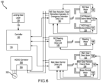
- System 320 for controlling landing gear subsystems is illustrated.
- System 320 is similar to system 120 in FIGs. 3 and 4 , but includes various redundancies. Elements with like element numbering, as depicted in FIG. 3 , are intended to be the same and will not necessarily be repeated for the sake of clarity.
- system 320 includes controller 122, motor drive units 130, 140, 150, and motors 132, 134, 136, 142, 152, 154, as described with reference to system 120 in FIGs. 3 and 4 .
- System 320 further includes AC/DC converter 200, AC power supply 202, and braking resistor 204.
- system 320 may further include a secondary controller 322, similar to controller 122, and having one or more processors and one or more tangible, non-transitory storage medium(s), or memories, 324.
- secondary controller 322 may be in communication with and/or may provide commands to motor drive units 130, 140, 150. Secondary controller 322 may be identical, or nearly identical, to controller 122, and may provide redundancy should controller 122 fail.
- system 320 may further include a secondary nose gear door actuation, gear retraction-extension, and emergency extension motor drive unit 330 (referred to herein as secondary nose gear motor drive unit 330).
- Secondary nose gear motor drive unit 330 is operationally coupled to secondary controller 322.
- Secondary nose gear motor drive unit 330 is configured to drive nose gear door motor 132, nose gear retraction-extension motor 134, and emergency nose gear extension motor 136 in response to commands from secondary controller 322.
- secondary nose gear motor drive unit 330 may be in communication with and/or receive commands from both controller 122 and secondary controller 322.
- Secondary nose gear motor drive unit 330 may be identical, or nearly identical, to nose gear motor drive unit 130 and may provide redundancy should nose gear motor drive unit 130 fail.
- System 320 may further include a secondary steering motor drive unit 340 operationally coupled to secondary controller 322.
- Secondary steering motor drive unit 340 is configured to drive steering control motor 142 in response to commands from secondary controller 322.
- secondary steering motor drive unit 340 may be in communication with and/or receive commands from both controller 122 and secondary controller 322.
- Secondary steering motor drive unit 340 may be identical, or nearly identical, to steering motor drive unit 140 and may provide redundancy should steering motor drive unit 140 fail.
- System 320 may further include a secondary main gear motor drive unit 350 operationally coupled to secondary controller 322.
- Secondary main gear motor drive unit 350 is configured to drive the main gear door motors 152 and the brake control motors 154 in response to commands from secondary controller 322.
- secondary main gear motor drive unit 350 may be in communication with and/or receive commands from both controller 122 and secondary controller 322.
- Secondary main gear motor drive unit 350 may be identical, or nearly identical, to main gear motor drive unit 150 and may provide redundancy should main gear motor drive unit 150 fail.
- system 320 includes a secondary AC/DC converter 370 configured to provide power (e.g., DC current) to each of secondary motor drive units 330, 340, 350.
- Secondary AC/DC converter 370 may be electrically coupled to a secondary AC power supply 372.
- secondary AC/DC converter 370 may be electrically coupled to both motor drive units 130, 140, 150 and secondary motor drive units 330, 340, 350.
- Secondary AC/DC converter 370 may be identical, or nearly identical, to AC/DC converter 200 and may provide redundancy should AC/DC converter 200 fail.
- system 320 may also include a secondary braking resistor 374 electrically coupled to secondary motor drive units 330, 340, 350.
- Secondary braking resistor 374 may dissipate the regeneration energy of the secondary motor drive units 330, 340, 350.
- secondary braking resistor 374 may be electrically coupled to both motor drive units 130, 140, 150 and secondary motor drive units 330, 340, 350.
- Secondary braking resistor 374 may be identical, or nearly identical, to braking resistor 204 and may provide redundancy should braking resistor 204 fail.
- System 420 for controlling landing gear subsystems is illustrated.
- System 420 may be similar to system 120 in FIGs. 3 and 4 .
- Elements with like element numbering, as depicted in FIG. 3 are intended to be the same and will not necessarily be repeated for the sake of clarity.
- main gear motor drive unit 150 of system 420 may be configured to drive the main gear door motors 152, the brake control motors 154, and one or more main gear retraction-extension motor(s) 156.
- main gear retraction-extension motors 156 may comprise electric motors (e.g., PMSMs, BLDC motors, or any other suitable electric motor).
- Main gear retraction-extension motors 156 may be configured to drive one or more hydraulic pumps that supply hydraulic pressure and fluid flow to hydraulic actuators configured to control retraction and extension of main landing gear 12, 14.
- main landing gear 12, 14 may be controlled by electro hydrostatic actuators, and main gear motor drive unit 150 may provide power (i.e., current) to the electro hydrostatic actuators.
- main landing gear 12, 14 may be translated between the landing gear up and landing gear down positions electrically (e.g., via EMAs).
- main gear retraction-extension motors 156 may translate main landing gear 12, 14 between the landing gear down and landing gear up positions.
- main gear door motors 152, brake control motors 154, and main gear retraction-extension motors 156 may be operated at different times (i.e., not simultaneously).
- a single main gear motor drive unit 150 may be employed to operate (i.e., drive) main gear door motors 152, brake control motors 154, and main gear retraction-extension motors 156.
- main gear motor drive unit 150 is driving main gear retraction-extension motors 156
- main gear door motors 152 and brake control motors 154 may be dormant (i.e., powered off).
- System 420 may include one or more main gear retraction sensors 192 may include one or more main gear retraction sensors 192 operationally coupled to main gear retraction-extension motors 156 and/or to components of main landing gear 12, 14 (e.g., to shock structs of left landing gear 12 and right landing gear 14).
- the output of main retraction sensors 192 may correlate to one or more operating conditions of main gear retraction-extension motors 156 (e.g., velocity, position, etc.).
- the output of main retraction sensors 192 may also provide information related to the position of main landing gear 12, 14 (e.g., extended, retracted, etc.).
- the output of main retraction sensors 192 may be received by main gear motor drive unit 150.
- main gear motor drive unit 150 may also drive one or emergency main gear extension motors and may make decisions related to the operation of the emergency main gear extension motors based on the signals output from main gear retraction sensors 192, similar to nose gear motor drive unit 130 and emergency nose gear extension motor 136.
- controller 122 may output commands to main gear motor drive unit 150 configured to cause main gear motor drive unit 150 to power (or excite) main retraction sensors 192, when main gear retraction-extension motors 156 are in operation.
- main retraction sensors 192 may also operate (i.e., receive power and provide output) when main gear retraction-extension motors 156 are turned off.
- references to "one embodiment,” “an embodiment,” “various embodiments,” etc. indicate that the embodiment described may include a particular feature, structure, or characteristic, but every embodiment may not necessarily include the particular feature, structure, or characteristic. Moreover, such phrases are not necessarily referring to the same embodiment. Further, when a particular feature, structure, or characteristic is described in connection with an embodiment, it is submitted that it is within the knowledge of one skilled in the art to affect such feature, structure, or characteristic in connection with other embodiments whether or not explicitly described. After reading the description, it will be apparent to one skilled in the relevant art(s) how to implement the disclosure in alternative embodiments. The scope of the invention is defined by the claims.
Landscapes
- Engineering & Computer Science (AREA)
- Mechanical Engineering (AREA)
- Aviation & Aerospace Engineering (AREA)
- Maintenance And Inspection Apparatuses For Elevators (AREA)
- Elevator Door Apparatuses (AREA)
- Gear Transmission (AREA)
- Control Of Multiple Motors (AREA)
- Power-Operated Mechanisms For Wings (AREA)
Applications Claiming Priority (3)
| Application Number | Priority Date | Filing Date | Title |
|---|---|---|---|
| IN202041009543 | 2020-03-05 | ||
| US17/128,143 US11472539B2 (en) | 2020-03-05 | 2020-12-20 | Distributed landing gear system architecture for electromechanical actuation |
| EP21160942.5A EP3875365B1 (de) | 2020-03-05 | 2021-03-05 | Verteilte fahrwerkssystemarchitektur für elektromechanische betätigung |
Related Parent Applications (1)
| Application Number | Title | Priority Date | Filing Date |
|---|---|---|---|
| EP21160942.5A Division EP3875365B1 (de) | 2020-03-05 | 2021-03-05 | Verteilte fahrwerkssystemarchitektur für elektromechanische betätigung |
Publications (2)
| Publication Number | Publication Date |
|---|---|
| EP4458668A2 true EP4458668A2 (de) | 2024-11-06 |
| EP4458668A3 EP4458668A3 (de) | 2025-01-22 |
Family
ID=74859294
Family Applications (2)
| Application Number | Title | Priority Date | Filing Date |
|---|---|---|---|
| EP24201773.9A Withdrawn EP4458668A3 (de) | 2020-03-05 | 2021-03-05 | Verteilte fahrwerkssystemarchitektur für elektromechanische betätigung |
| EP21160942.5A Active EP3875365B1 (de) | 2020-03-05 | 2021-03-05 | Verteilte fahrwerkssystemarchitektur für elektromechanische betätigung |
Family Applications After (1)
| Application Number | Title | Priority Date | Filing Date |
|---|---|---|---|
| EP21160942.5A Active EP3875365B1 (de) | 2020-03-05 | 2021-03-05 | Verteilte fahrwerkssystemarchitektur für elektromechanische betätigung |
Country Status (2)
| Country | Link |
|---|---|
| EP (2) | EP4458668A3 (de) |
| BR (1) | BR102021003968A2 (de) |
Families Citing this family (2)
| Publication number | Priority date | Publication date | Assignee | Title |
|---|---|---|---|---|
| JP7067983B2 (ja) * | 2018-03-22 | 2022-05-16 | クノールブレムゼステアリングシステムジャパン株式会社 | 車両搭載機器 |
| CN117602067A (zh) * | 2023-11-28 | 2024-02-27 | 道尼尔海翼无锡有限公司 | 一种轻量化可编程起落架系统及其控制方法 |
Citations (3)
| Publication number | Priority date | Publication date | Assignee | Title |
|---|---|---|---|---|
| US20130082149A1 (en) | 2010-06-18 | 2013-04-04 | Sagem Defense Securite | Power supply and control device for actuators, corresponding actuation assembly, and aircraft comprising such a device |
| US20140100719A1 (en) | 2012-10-09 | 2014-04-10 | Messier-Bugatti-Dowty | Electromechanical braking system architecture |
| US20180370619A1 (en) | 2015-12-02 | 2018-12-27 | Ihi Corporation | Electric taxiing system of aircraft and method for controlling the system |
Family Cites Families (3)
| Publication number | Priority date | Publication date | Assignee | Title |
|---|---|---|---|---|
| FR2898337B1 (fr) * | 2006-03-13 | 2009-02-13 | Messier Bugatti Sa | Architecture de distribution de puissance pour actionnements en sequence d'elements mobiles d'un aeronef |
| FR2968483B1 (fr) * | 2010-12-06 | 2015-09-04 | Messier Bugatti | Procede de commande d'un moteur a courant continu sans balai. |
| US9787101B2 (en) * | 2014-09-09 | 2017-10-10 | Honeywell International Inc. | Bidirectional conversion architecture with energy storage |
-
2021
- 2021-03-02 BR BR102021003968-0A patent/BR102021003968A2/pt not_active Application Discontinuation
- 2021-03-05 EP EP24201773.9A patent/EP4458668A3/de not_active Withdrawn
- 2021-03-05 EP EP21160942.5A patent/EP3875365B1/de active Active
Patent Citations (3)
| Publication number | Priority date | Publication date | Assignee | Title |
|---|---|---|---|---|
| US20130082149A1 (en) | 2010-06-18 | 2013-04-04 | Sagem Defense Securite | Power supply and control device for actuators, corresponding actuation assembly, and aircraft comprising such a device |
| US20140100719A1 (en) | 2012-10-09 | 2014-04-10 | Messier-Bugatti-Dowty | Electromechanical braking system architecture |
| US20180370619A1 (en) | 2015-12-02 | 2018-12-27 | Ihi Corporation | Electric taxiing system of aircraft and method for controlling the system |
Also Published As
| Publication number | Publication date |
|---|---|
| EP3875365A2 (de) | 2021-09-08 |
| EP3875365B1 (de) | 2024-10-09 |
| BR102021003968A2 (pt) | 2021-09-14 |
| EP4458668A3 (de) | 2025-01-22 |
| EP3875365A3 (de) | 2021-11-17 |
Similar Documents
| Publication | Publication Date | Title |
|---|---|---|
| CN102947177B (zh) | 用于致动器的供电和控制设备、相应的致动组件、以及包括该设备的飞行器 | |
| US9108740B2 (en) | Method for generating hydraulic power in an aircraft, use of a hybrid power control unit and drive system | |
| US8175762B2 (en) | Electrically activated aircraft landing gear control system and method | |
| CN101140004B (zh) | 飞机动力系统和用于控制飞机系统的方法 | |
| US8698444B2 (en) | Aircraft electrical actuator arrangement | |
| EP3875365B1 (de) | Verteilte fahrwerkssystemarchitektur für elektromechanische betätigung | |
| US7939962B2 (en) | System and method for supplying power to user systems onboard an aircraft | |
| EP3095693A1 (de) | Flugzeuglenksystem | |
| US8430354B2 (en) | Flight control system for an aircraft | |
| CA2629552A1 (en) | Method and device for redundantly supplying several electric servomotors or drive motors by means of a common power electronics unit | |
| CN113534656A (zh) | 一种电传飞行备份控制系统和方法 | |
| EP3848279A1 (de) | Systeme zum ernten von drehradenergie zum einfahren des fahrwerks | |
| US20180274563A1 (en) | Aircraft Hydraulic Systems Having Shared Components | |
| EP2727831A1 (de) | Verfahren zum Übertragen von hydraulischer Leistung zwischen zwei hydraulischen Systemen in einem Flugzeug, Verwendung einer Leistungssteuerungseinheit und Antriebssystem in einem Flugzeug | |
| CN110683050A (zh) | 飞行器 | |
| US11472539B2 (en) | Distributed landing gear system architecture for electromechanical actuation | |
| US20160031553A1 (en) | Electric braking system with power conservation and method of operating the same | |
| EP3556652B1 (de) | Elektrohydrostatische bremssteuerung | |
| US12325511B2 (en) | Landing gear actuating device with double-star motor | |
| EP3998203A1 (de) | Flugzeugfahrwerkanordnung und flugzeug | |
| JP2020026210A (ja) | 脚揚降システム |
Legal Events
| Date | Code | Title | Description |
|---|---|---|---|
| PUAI | Public reference made under article 153(3) epc to a published international application that has entered the european phase |
Free format text: ORIGINAL CODE: 0009012 |
|
| STAA | Information on the status of an ep patent application or granted ep patent |
Free format text: STATUS: THE APPLICATION HAS BEEN PUBLISHED |
|
| AC | Divisional application: reference to earlier application |
Ref document number: 3875365 Country of ref document: EP Kind code of ref document: P |
|
| AK | Designated contracting states |
Kind code of ref document: A2 Designated state(s): AL AT BE BG CH CY CZ DE DK EE ES FI FR GB GR HR HU IE IS IT LI LT LU LV MC MK MT NL NO PL PT RO RS SE SI SK SM TR |
|
| REG | Reference to a national code |
Ref country code: DE Ref legal event code: R079 Free format text: PREVIOUS MAIN CLASS: B64C0025100000 Ipc: B64C0025240000 |
|
| PUAL | Search report despatched |
Free format text: ORIGINAL CODE: 0009013 |
|
| AK | Designated contracting states |
Kind code of ref document: A3 Designated state(s): AL AT BE BG CH CY CZ DE DK EE ES FI FR GB GR HR HU IE IS IT LI LT LU LV MC MK MT NL NO PL PT RO RS SE SI SK SM TR |
|
| RIC1 | Information provided on ipc code assigned before grant |
Ipc: B64C 25/42 20060101ALN20241213BHEP Ipc: B64C 25/16 20060101ALN20241213BHEP Ipc: B64C 25/10 20060101ALI20241213BHEP Ipc: B64C 25/26 20060101ALI20241213BHEP Ipc: B64C 25/24 20060101AFI20241213BHEP |
|
| STAA | Information on the status of an ep patent application or granted ep patent |
Free format text: STATUS: REQUEST FOR EXAMINATION WAS MADE |
|
| 17P | Request for examination filed |
Effective date: 20250722 |
|
| STAA | Information on the status of an ep patent application or granted ep patent |
Free format text: STATUS: THE APPLICATION IS DEEMED TO BE WITHDRAWN |
|
| 18D | Application deemed to be withdrawn |
Effective date: 20250723 |