EP4458621A1 - Airbag device - Google Patents
Airbag device Download PDFInfo
- Publication number
- EP4458621A1 EP4458621A1 EP22915538.7A EP22915538A EP4458621A1 EP 4458621 A1 EP4458621 A1 EP 4458621A1 EP 22915538 A EP22915538 A EP 22915538A EP 4458621 A1 EP4458621 A1 EP 4458621A1
- Authority
- EP
- European Patent Office
- Prior art keywords
- cushion
- duct
- sub chamber
- vehicle
- airbag device
- Prior art date
- Legal status (The legal status is an assumption and is not a legal conclusion. Google has not performed a legal analysis and makes no representation as to the accuracy of the status listed.)
- Pending
Links
Images




Classifications
-
- B—PERFORMING OPERATIONS; TRANSPORTING
- B60—VEHICLES IN GENERAL
- B60R—VEHICLES, VEHICLE FITTINGS, OR VEHICLE PARTS, NOT OTHERWISE PROVIDED FOR
- B60R21/00—Arrangements or fittings on vehicles for protecting or preventing injuries to occupants or pedestrians in case of accidents or other traffic risks
- B60R21/02—Occupant safety arrangements or fittings, e.g. crash pads
- B60R21/16—Inflatable occupant restraints or confinements designed to inflate upon impact or impending impact, e.g. air bags
- B60R21/20—Arrangements for storing inflatable members in their non-use or deflated condition; Arrangement or mounting of air bag modules or components
- B60R21/213—Arrangements for storing inflatable members in their non-use or deflated condition; Arrangement or mounting of air bag modules or components in vehicle roof frames or pillars
-
- B—PERFORMING OPERATIONS; TRANSPORTING
- B60—VEHICLES IN GENERAL
- B60R—VEHICLES, VEHICLE FITTINGS, OR VEHICLE PARTS, NOT OTHERWISE PROVIDED FOR
- B60R21/00—Arrangements or fittings on vehicles for protecting or preventing injuries to occupants or pedestrians in case of accidents or other traffic risks
- B60R21/02—Occupant safety arrangements or fittings, e.g. crash pads
- B60R21/16—Inflatable occupant restraints or confinements designed to inflate upon impact or impending impact, e.g. air bags
- B60R21/23—Inflatable members
- B60R21/231—Inflatable members characterised by their shape, construction or spatial configuration
- B60R21/232—Curtain-type airbags deploying mainly in a vertical direction from their top edge
-
- B—PERFORMING OPERATIONS; TRANSPORTING
- B60—VEHICLES IN GENERAL
- B60R—VEHICLES, VEHICLE FITTINGS, OR VEHICLE PARTS, NOT OTHERWISE PROVIDED FOR
- B60R21/00—Arrangements or fittings on vehicles for protecting or preventing injuries to occupants or pedestrians in case of accidents or other traffic risks
- B60R21/02—Occupant safety arrangements or fittings, e.g. crash pads
- B60R21/16—Inflatable occupant restraints or confinements designed to inflate upon impact or impending impact, e.g. air bags
- B60R21/23—Inflatable members
- B60R21/231—Inflatable members characterised by their shape, construction or spatial configuration
- B60R21/233—Inflatable members characterised by their shape, construction or spatial configuration comprising a plurality of individual compartments; comprising two or more bag-like members, one within the other
-
- B—PERFORMING OPERATIONS; TRANSPORTING
- B60—VEHICLES IN GENERAL
- B60R—VEHICLES, VEHICLE FITTINGS, OR VEHICLE PARTS, NOT OTHERWISE PROVIDED FOR
- B60R21/00—Arrangements or fittings on vehicles for protecting or preventing injuries to occupants or pedestrians in case of accidents or other traffic risks
- B60R21/02—Occupant safety arrangements or fittings, e.g. crash pads
- B60R21/16—Inflatable occupant restraints or confinements designed to inflate upon impact or impending impact, e.g. air bags
- B60R21/23—Inflatable members
- B60R21/237—Inflatable members characterised by the way they are folded
-
- B—PERFORMING OPERATIONS; TRANSPORTING
- B60—VEHICLES IN GENERAL
- B60R—VEHICLES, VEHICLE FITTINGS, OR VEHICLE PARTS, NOT OTHERWISE PROVIDED FOR
- B60R21/00—Arrangements or fittings on vehicles for protecting or preventing injuries to occupants or pedestrians in case of accidents or other traffic risks
- B60R21/02—Occupant safety arrangements or fittings, e.g. crash pads
- B60R21/16—Inflatable occupant restraints or confinements designed to inflate upon impact or impending impact, e.g. air bags
- B60R2021/161—Inflatable occupant restraints or confinements designed to inflate upon impact or impending impact, e.g. air bags characterised by additional means for controlling deployment trajectory
-
- B—PERFORMING OPERATIONS; TRANSPORTING
- B60—VEHICLES IN GENERAL
- B60R—VEHICLES, VEHICLE FITTINGS, OR VEHICLE PARTS, NOT OTHERWISE PROVIDED FOR
- B60R21/00—Arrangements or fittings on vehicles for protecting or preventing injuries to occupants or pedestrians in case of accidents or other traffic risks
- B60R21/02—Occupant safety arrangements or fittings, e.g. crash pads
- B60R21/16—Inflatable occupant restraints or confinements designed to inflate upon impact or impending impact, e.g. air bags
- B60R21/23—Inflatable members
- B60R21/231—Inflatable members characterised by their shape, construction or spatial configuration
- B60R21/233—Inflatable members characterised by their shape, construction or spatial configuration comprising a plurality of individual compartments; comprising two or more bag-like members, one within the other
- B60R2021/23308—Inflatable members characterised by their shape, construction or spatial configuration comprising a plurality of individual compartments; comprising two or more bag-like members, one within the other the individual compartments defining the external shape of the bag
-
- B—PERFORMING OPERATIONS; TRANSPORTING
- B60—VEHICLES IN GENERAL
- B60R—VEHICLES, VEHICLE FITTINGS, OR VEHICLE PARTS, NOT OTHERWISE PROVIDED FOR
- B60R21/00—Arrangements or fittings on vehicles for protecting or preventing injuries to occupants or pedestrians in case of accidents or other traffic risks
- B60R21/02—Occupant safety arrangements or fittings, e.g. crash pads
- B60R21/16—Inflatable occupant restraints or confinements designed to inflate upon impact or impending impact, e.g. air bags
- B60R21/26—Inflatable occupant restraints or confinements designed to inflate upon impact or impending impact, e.g. air bags characterised by the inflation fluid source or means to control inflation fluid flow
- B60R21/261—Inflatable occupant restraints or confinements designed to inflate upon impact or impending impact, e.g. air bags characterised by the inflation fluid source or means to control inflation fluid flow with means other than bag structure to diffuse or guide inflation fluid
- B60R2021/2612—Gas guiding means, e.g. ducts
Definitions
- the present invention relates to an airbag device provided with a curtain airbag that expands and deploys along a side surface inside a vehicle for the purpose of protecting the occupant during a side collision or rollover of the vehicle.
- Curtain airbags must deploy along a side surface of a vehicle to cover all regions where the occupant's head and upper body may be impacted, even if the vehicle transitions from a side collision to a rollover.
- curtain airbags are mounted to the chassis such as a roof side rail positioned at an upper part of a side surface in a vehicle cabin and stowed in a rolled or folded state in a stow space between the chassis and garnish such as a roof headlining position above the door.
- Curtain airbags typically have a plurality of tabs provided at prescribed intervals on an upper end part thereof. Curtain airbags can be suspended from the upper part of the side surface inside the vehicle cabin by attaching each tab to the chassis via a bracket.
- a curtain airbag disclosed in Patent Document 1 includes a front chamber, a first gas supply opening, a sub chamber, and a second gas supply opening.
- the front chamber expands and deploys along the side window of the vehicle front seat.
- the first gas supply opening is arranged above the front chamber and supplies gas to the front chamber.
- the sub chamber is a chamber arranged above the front chamber that is smaller than the front chamber.
- the second gas supply opening is arranged behind the sub chamber, is connected to the first gas supply opening, and is narrower than the first gas supply opening.
- the sub chamber is stowed in a folded state at a portion of the second gas supply opening on the vehicle interior surface of the front chamber.
- Patent Document 1 after first causing the front chamber to expand and deploy during expansion and deployment of the curtain airbag, the sub chamber can be expanded and deployed enabling expansion and deployment of the sub chamber while suppressing interference between the A pillar garnish and the sub chamber and covering the A pillar.
- Patent Document 1 Japanese Unexamined Patent Application 2018-114828
- the region (protective area) to be covered during expansion and deployment of the curtain airbag was specified.
- the cushion is suspended from the upper part of the side surface inside the vehicle cabin by tabs during expansion and deployment.
- the length of the tab needs to be set with consideration for the shape of the cushion in a stowed state and the deployment behavior of the cushion.
- the length of the tab is set with consideration for ensuring suitable deployment behavior of the cushion and for the shape of the cushion in the stowed state.
- Patent Document 1 is nothing more than simply the cushion covering the A pillar and no measures are taken to address the problem of tab length causing inability to sufficiently cover the protective area.
- an object of the present invention is to provide an airbag device enabling reliably covering an appropriate range with a cushion and increasing occupant protection performance while ensuring suitable deployment behavior at a position a tab is attached.
- a typical configuration for an airbag device comprises: a cushion stowed rolled or folded at an upper part of a side surface inside a vehicle cabin that expands and deploys along the side surface, comprising: an inflator inserted inside the cushion that supplies gas to the cushion; and a tab for suspending the cushion from an upper part of the side surface; wherein the cushion includes:
- the length of the tab for suspending the cushion from the upper part of the side surface inside the vehicle cabin needs to be set with consideration for ensuring suitable deployment behavior of the cushion and for the shape of the cushion in the stowed state.
- a certain length of tab needs to be ensured, and this may lead to cases where the cushion was not sufficiently lifted by the tabs causing an area (gap) below the upper edge of the side window that was not covered.
- the tab is attached with the cushion of the configuration described above, in addition to the main chamber, the upper end of the sub chamber is positioned above the upper edge of the side window. Furthermore, the lower end of the sub chamber is attached to the tab or positioned lower than the upper end of an integral duct.
- the sub chamber can cover between the upper end of the duct and the upper edge of the side window and can cover the gap below the upper edge of the side window.
- covering an appropriate range with a cushion and increasing occupant protection performance while ensuring suitable deployment behavior at a position a tab is attached is feasible.
- the sub chamber described above expands and deploys more to the outside of the vehicle than the duct and the position is restricted by contact with the weather strip attached to the lower end of the roof side rail at the upper part of the side surface.
- the sub chamber expands and deploys more to the outside of the vehicle than the duct and the position of the sub chamber is restricted in the vertical direction of the vehicle by contact with the weather strip at the lower end of the roof side rail.
- the lower end of the expanded and deployed sub chamber can be positioned below the upper end of the duct and the upper end of the sub chamber can be positioned above the upper edge of the side window of the vehicle.
- the sub chamber described above includes a leg part connected to the duct and a portion extending from the leg part in the front-to-back direction of the vehicle, and the tab may be attached to the duct at a location positioned somewhere on the portion extending in the front-to-back direction of the vehicle.
- the sub chamber includes a leg part and a portion extending therefrom in the front-to-back direction of the vehicle so the tab can be attached to a portion of the duct at a location positioned somewhere on the portion extending in the front-to-back direction of the vehicle.
- the cushion can be suspended in a suitable position by the tab.
- the sub chamber is formed in a bridge shape with a pair of legs separated in the front-to-back direction and connected to the duct and a connecting part that connects the pair of legs, and the tab is attached in a portion of the duct positioned between the pair of legs.
- the sub chamber has a bridge shape so the tab can be attached at a location positioned between the pair of legs.
- the cushion can be suspended in a suitable position by the tab.
- the connecting part of the sub chamber folds and bends to the outside of the vehicle during expansion and deployment and may be positioned between the pair of legs and the upper edge of the side window.
- the sub chamber can reliably cover the gap below the upper edge of the side window based on the connecting part folded and bent toward the outside of the vehicle during expansion and deployment.
- a retaining member that is wound on an outer surface of the cushion in a stowed state and that breaks during cushion deployment is connected to the portion of the duct described above.
- a retaining member (tape) can be wound on the cushion at the portion of the duct positioned between the pair of legs of the bridge shaped sub chamber. Therefore, the tape can be wound at an appropriate position of the cushion in a stowed state, enabling readily winding with the tape and maintaining the shape of the cushion.
- the sub chamber described above may include a blocking part that blocks one of the pair of legs from the duct. Even if the blocking part is provided, gas flows in from the duct to the other leg part enabling the sub chamber to expand and deploy.
- the region between the sub chamber described above and the portion extending in the front-to-back direction of the vehicle may be hollow or made up of a non-expanding region that does not expand.
- the region between the sub chamber described above and connecting part may be hollow or made up of a non-expanding region that does not expand.
- an airbag device enabling reliably covering an appropriate range with a cushion and increasing occupant protection performance while ensuring suitable deployment behavior at a position a tab is attached can be provided.
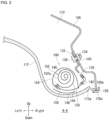
- FIG. 1 is a schematic diagram depicting an airbag device 100 of an embodiment of the present invention.
- FIG. 2 is a cross section view along A-A of the airbag device 100 in FIG. 1(a).
- FIG. 1 (a) illustrates the non-deployed state (stowed) of a curtain airbag (cushion 102).
- the cushion 102 depicted in FIG. 1(a) is for the right side surface of the vehicle and while not depicted, a cushion for the left side surface has a similar symmetrical structure.
- FIG. 1(b) is a diagram depicting the expanded and deployed condition of the main part of the cushion 102 of FIG. 1(a) .
- the direction the occupant faces is referred to as front, and the opposite direction is referred to as rear.
- the right of the occupant is referred to as the right direction
- the left of the occupant is referred to as the left direction.
- the direction towards the head of the occupant is referred to as up
- the direction towards the legs of the occupant is referred to as down.
- any diagrams used in descriptions below will indicate the front, rear, left, right, up, and down directions based on the occupant as described above as Front, Rear, Left, Right, Up, and Down.
- the airbag device 100 is provided with an inflator 104 that is a gas generating device and the cushion 102 expands and deploys to restrain the occupant based on gas pressure supplied from the inflator 104.
- the cushion 102 is formed into a bag shape, for example, by sewing the base fabric constituting the cushion surface on the front and back sides or by weaving the fabric using OPW (One-Piece Woven).
- the cushion 102 is mounted to a roof side rail 106 depicted in the drawing in a rolled state as indicated in FIG. 1(a) .
- the roof side rail 106 is positioned on an upper side of the interior of the vehicle 108 and forms the vehicle body side wall.
- the rolled cushion 102 is stowed in a stow space 110.
- the stow space 110 is formed, for example, by assembling a garnish 112 such as a roof headlining to the roof side rail 106. Note that the garnish 112 is omitted from depiction in FIG. 1(a) .
- the vehicle 108 depicted in FIG. 1(a) is a vehicle with two rows arranged as a front seat 114 and a back seat 116 from the front of the vehicle.
- side windows 118 and 120 are installed on a side surface of the vehicle 108. Pillars supporting the roof are provided in the vehicle front-to-back direction for each of the side windows 118 and 120.
- these pillars are referred to as a front pillar 122, a center pillar 124, and a rear pillar 126.
- the cushion 102 For the airbag device 100, in an emergency such as a side collision, gas is supplied to expand the cushion 102, and thereby the cushion 102 pushes the garnish 112 toward the inside of the vehicle and an end part 112a of the garnish 112 in contact with the roof side rail 106 depicted in FIG. 2 is lowered. Therefore, the cushion 102 appears from a gap between the garnish 112 and a lower end 106a of the roof side rail 106 and expands and deploys along a side surface of the vehicle cabin.
- a weather strip 128 is attached to the lower end 106a of the roof side rail 106.
- the airbag device 100 is provided with a tab 130 as depicted in FIG. 2 .
- the tab 130 is a plurality of strip shaped members on the cushion 102 at prescribed intervals that suspend the cushion 102 from an upper part of the side surface inside the vehicle cabin.
- the tab 130 is mounted to a bracket 132 secured to the vehicle, in other words the roof side rail 106.
- the bracket 132 is, for example, made of metal and has a bolt hole 134 and an insertion hole 136, through which the tab 130 is inserted and folded back.
- the bracket 132 is secured to the roof side rail 106 by screwing a bolt 138 passed through the bolt hole 134 and a nut 140, as depicted in FIG. 2 .
- the tabs 130 are sewn and attached as indicated by a sewing line 142 in a folded and overlapped state at the insertion hole 136 of the bracket 132.
- the cushion 102 has a duct 144, main chamber 146, and sub chamber 148 at the position where the tab 130 is attached, and these areas are expansion regions that expand due to gas from the inflator 104 flowing thereinto, as indicated by the arrow B in FIG. 1(b) . Note that in FIG. 1(b) , the tab 130 and bracket 132 depicted in FIG. 2 are omitted.
- the duct 144 extends in the front-to-back direction of the vehicle and as indicated by a sewing line 150 in FIG. 2 , the tab 130 is sewn and attached to the duct 144 (cushion 102). Note that the tab 130 does not necessarily need to be attached to the cushion 102 by sewing and may be attached by other means or integrated with the cushion 102.
- the main chamber 146 is demarcated by a seam part 152 depicted in FIG. 1(b) and is positioned lower than the duct 144. Note that the duct 144 and the main chamber 146 that constitute the cushion 102 do not necessarily need to be compartmentalized. In the case of non-compartmentalization (no duct 144), of course the tab 130 can be attached or integrated directly with the main chamber.
- the seam part 152 is formed by joining the cloth of the front and back of the cushion 102 together.
- a retaining member (tape 154) is wound around an outer surface 102a of the cushion 102 in a stowed state.
- the tape 154 is wound around the outer surface 102a of the cushion 102.
- the tape 154 is a fragile member that breaks due to pressure caused by expansion and deployment of the cushion 102, and so does not hinder deployment of the cushion 102.
- Tape 154 may be fabric or non-woven fabric.
- the sub chamber 148 is provided on the side surface inside the vehicle cabin and is integrated with the cushion 102 together with the main chamber 144 [sic].
- the length of the tab 130 is set with consideration for the shape of the cushion 102 in a stowed state and the deployment behavior of the cushion 102.
- the tab 130 being too short will affect the deployment behavior of the cushion 102 such as causing a change in the deployment direction of the cushion 102. Therefore, the length of the tab 130 needs to be set with consideration for ensuring suitable deployment behavior of the cushion 102 and for the shape of the cushion 102 in the stowed state.
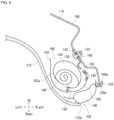
- FIG. 3 is a diagram depicting a state of a cushion 102 of the airbag device 100 of FIG. 1(a) expanded and deployed. Note that the cushion 102 of FIG. 1(b) depicts an expanded and deployed state without restrictions on the sub chamber 148 position. On the other hand, the cushion 102 of the FIG. 3(a) depicts a state of the sub chamber 148 position being restricted due to contact with the roof side rail 106 or the like.
- FIG. 3(b) is a view depicting a portion of FIG. 3(a) in an enlarged manner.
- the region that the cushion 102 should cover when expanded and deployed in other words, the protective area 156 (see Figure 3(a) ), has been defined.
- the airbag device 100 at the position the tab 130 is attached, a certain length of the tab 130 needs to be ensured with consideration for the deployment behavior of the cushion 102, as described above.
- the sub chamber 148 has a pair of legs 164 and 166 and connecting part 168, and is formed in a bridge shape as depicted in FIG. 1(b) .
- the pair of legs 164 and 166 are separated in the front-to-back direction of the vehicle and are connected to the duct 144.
- the connecting part 168 connects the pair of legs 164 and 166 and is separated from the duct 144.
- the sub chamber 148 has a bridge shape so the tab 130 depicted in FIG. 2 can be attached to a portion 170 (see FIG. 1(b) ) of the duct 144 positioned between the pair of legs 164 and 166.
- the cushion 102 can be suspended in a suitable position by the tab 130.
- the region 171 between the connecting part 168 of the sub chamber 148 and the duct 144 is hollow in the present Embodiment.
- the region 171 may be a non expanding region that does not expand such as fabric.
- the connecting part 168 being folded and bent to the outside during expansion and deployment, the bridge shaped sub chamber 148 covers the gap 162 between the upper edge 158 of the side window 118 and the upper end 160 of the duct 144, as depicted in FIG. 3(b) .
- deployment behavior of the cushion 102 will be described.
- FIG. 4 is a diagram depicting a state of the cushion 102 of the airbag device 100 of FIG. 2 partially deployed.
- the sub chamber 148 of the cushion 102 expands and presses on the garnish 112 causing the end part 112a of the garnish 112 to lower.
- the sub chamber 148 comes into contact with the weather strip 128 attached to the lower end 106a of the roof side rail 106.
- a lower end 128a of the weather strip 128 is positioned at roughly the same height as the upper edge 158 of the side window 118 depicted in FIG. 3(b) .
- the duct 144 starts to expand while the main chamber 146 has not yet expanded.
- tape 154 wound on the outer surface 102a of the cushion 102 is broken by pressure associated with expansion and deployment of the cushion 102, as depicted.
- FIG. 5 is a diagram depicting a state continuing from FIG. 4 with the cushion 102 expanded and deployed. Note that the state during expansion and deployment of the cushion 102 of FIG. 5 corresponds to the state of the cushion 102 in FIG. 3(b) .
- the connecting part 168 expands and deploys to the outside of the vehicle from the duct 144, as depicted, and the position in contact with the weather strip 128 attached to the lower end 106a of the roof side rail 106 is restricted.
- an upper end 172 of the connecting part 168 of the sub chamber 148 is positioned at the height of the upper edge 158 of the side window 118 indicated by a dotted line C in the diagram, in other words, above the height of the lower end 128a of the weather strip 128.
- a lower end 174 of the connecting part 168 of the sub chamber 148 is positioned below the height of the upper end 160 of the duct 144 indicated by dotted line D in the diagram.
- the height difference between dotted lines C and D corresponds to the height of the gap 162 depicted in FIG. 3(b) .
- the connecting part 168 is folded and bent to the outside of the vehicle during expansion and deployment and is positioned between the pair of legs 164 and 166 and the upper edge 158 of the side window 118. Furthermore, the length of the connecting part 168 of the sub chamber 148 in the vehicle front-to-back direction is longer than the length of the gap 162 in the vehicle front-to-back direction, as depicted in FIG. 3(b) .
- the sub chamber 148 can cover the gap 162 between the upper end 160 of the duct 144 and the upper edge 158 of the side window 118. Therefore, with the airbag device 100, at the position the tab 130 is mounted, appropriate deployment behavior of the cushion 102 can be ensured, the protective area 156 can be reliably covered by the cushion 102, enabling improvement of the protection performance of the occupant (see FIG. 3(a) ).
- tape 154 can be wound on the cushion 102 at the portion 170 (see FIG. 1(b) ) of the duct 144 positioned between the pair of legs 164 and 166 of the bridge shaped sub chamber 148. Therefore, the tape 154 can be wound at an appropriate position of the cushion 102 in a stowed state, enabling readily winding with the tape 154 and maintaining the shape of the cushion 102.
- FIG. 6 is a diagram depicting a modified example of the cushion depicted in FIG. 1(b) .
- similar elements within FIG. 1(b) are indicated using the same codes, and a description thereof is omitted.
- a sub chamber 248 of a cushion 202 of FIG. 6(a) is different from the sub chamber 148 of FIG. 1(b) .
- the sub chamber 248 includes a leg part 266 connected to the duct 144 and a portion 268 extending in the front-to-back direction of the vehicle from the leg part 266. Furthermore, the tab 130 is attached to a portion of the duct 144 that is positioned somewhere on the portion 268 extending in the front-to-back direction of the vehicle.
- a feature of the sub chamber 248 is including a single leg part 266.
- the sub chamber 248 is attached to the duct 144 by a non-expanding part 271, for example, fabric or the like without space inside for expanding, wound on the leg part 266 and on the outside of the portion 268.
- the sub chamber 248 includes a leg part 266 and a portion 268 extending therefrom in the front-to-back direction of the vehicle so the tab 130 can be attached to a portion of the duct 144 at a location positioned somewhere on the portion 268 extending in the front-to-back direction of the vehicle.
- the cushion 202 can be suspended in a suitable position by the tab 130.
- a region 273 between the portion 268 of the sub chamber 248 extending in the front-to-back direction of the vehicle and the duct 144 is hollow.
- the region 273 may also be a non-expanding region such as fabric that does not expand.
- a sub chamber 348 of a cushion 302 of FIG. 6(b) has a shape symmetrical with the sub chamber 248 of FIG. 6(a) .
- the sub chamber 348 has a single leg part 366 connected to the duct 144 on the vehicle front side and further, has a portion 368 extending from this leg part 366 in the front-to-back direction of the vehicle. Therefore, gas from the duct 144 enters the leg part 366 to the vehicle front side and then enters the portion 368 extending in the front-to-back direction of the vehicle and causes the sub chamber 348 to expand.
- FIG. 7 is a diagram depicting a modified example of the cushion depicted in FIG. 1(b) .
- similar elements within FIG. 1(b) are indicated using the same codes and a description thereof is omitted.
- a sub chamber 448 of a cushion 402 of FIG. 7(a) is different from the sub chamber 148 of FIG. 1(b) .
- the sub chamber 448 includes a blocking part 405 that blocks the leg part 164 to the front of the vehicle from the duct 144.
- a sub chamber 548 of a cushion 502 of FIG. 7(b) has a shape symmetrical with the sub chamber 448 of FIG. 7(a) .
- the sub chamber 548 has a blocking part 505 that blocks the leg part 166 to the back of the vehicle from the duct 144.
- the blocking parts 405 and 505 can be formed by sewing, for example. As indicated by FIG. 7(a) and (b) , even if blocking part 405 or 505 is provided, the other leg part 166 or 164 to which the blocking part is not provided will have gas enter therein from the duct 144, enabling the sub chamber 448 or 548 to expand and deploy.
- FIG. 8 is a diagram depicting a modified example of how the cushion depicted in FIG. 4 is stowed.
- similar elements within FIG. 4 are indicated using the same codes and a description thereof is omitted.
- the sub chamber 148 is sewn together with the tab 130 by the sewing line 150 at a location continuous with the duct 144 and a looped location.
- FIG. 9 is a diagram depicting a state continuing from FIG. 8 with the cushion 102 expanded and deployed.
- the connecting part 168 expands and deploys to the outside of the vehicle from the duct 144, as depicted, and the position in contact with the weather strip 128 attached to the lower end 106a of the roof side rail 106 is restricted.
- the same effect as that described for FIG. 5 can be obtained.
- the example in which the airbag device according to the present invention is applied to an automobile has been described in the embodiments described above.
- the present invention can be applied to aircrafts, ships, and the like, with the same operation and effects capable of being achieved.
- the present invention can be used as an airbag device provided with a curtain airbag that expands and deploys along a side surface inside a vehicle for the purpose of protecting the occupant during a side collision or rollover of the vehicle.
- Airbag device 102, 202, 302, 402, 502.
- Cushion 102a. Outer surface of cushion, 104.
- Inflator 106.
- Roof side rail 106a. Lower end of roof side rail, 108.
- Vehicle 110. Stow space, 112. Garnish, 112a. Lower end of garnish, 114.
- Side window 122.
- Weather strip 128a. Lower end of weather strip, 130.
- Tab 132. Bracket, 134.
- Bolt 140. Nut, 142, 150. Sewing line, 144.
- Duct 146. Main chamber, 148, 248, 348, 448, 548.
Landscapes
- Engineering & Computer Science (AREA)
- Mechanical Engineering (AREA)
- Air Bags (AREA)
- Physics & Mathematics (AREA)
- Fluid Mechanics (AREA)
Abstract
a cushion 102 that is rolled and stowed at an upper part of a side surface in a vehicle cabin and expands and deploys along the side surface,
an inflator 104 that is inserted in the cushion and provides gas to the cushion, and a tab 130 for suspending the cushion from the upper part of the side surface, wherein
the cushion includes:
a duct 144 provided with a tab extending in the front-to-back direction of the vehicle at the upper part of the side surface and that expands and deploys due to inflow of gas, a main chamber 146 positioned below the duct, and a sub chamber 148 provided at the upper part of the side surface,
the upper end 172 of the sub chamber is positioned above the upper edge 158 of the side window 118, and
the lower end 174 of the sub chamber is positioned below the upper end 160 of the duct.
Description
- The present invention relates to an airbag device provided with a curtain airbag that expands and deploys along a side surface inside a vehicle for the purpose of protecting the occupant during a side collision or rollover of the vehicle.
- Curtain airbags must deploy along a side surface of a vehicle to cover all regions where the occupant's head and upper body may be impacted, even if the vehicle transitions from a side collision to a rollover.
- Therefore, curtain airbags are mounted to the chassis such as a roof side rail positioned at an upper part of a side surface in a vehicle cabin and stowed in a rolled or folded state in a stow space between the chassis and garnish such as a roof headlining position above the door.
- Curtain airbags typically have a plurality of tabs provided at prescribed intervals on an upper end part thereof. Curtain airbags can be suspended from the upper part of the side surface inside the vehicle cabin by attaching each tab to the chassis via a bracket.
- A curtain airbag disclosed in Patent Document 1 includes a front chamber, a first gas supply opening, a sub chamber, and a second gas supply opening. The front chamber expands and deploys along the side window of the vehicle front seat. The first gas supply opening is arranged above the front chamber and supplies gas to the front chamber. The sub chamber is a chamber arranged above the front chamber that is smaller than the front chamber.
- The second gas supply opening is arranged behind the sub chamber, is connected to the first gas supply opening, and is narrower than the first gas supply opening. The sub chamber is stowed in a folded state at a portion of the second gas supply opening on the vehicle interior surface of the front chamber.
- In Patent Document 1, after first causing the front chamber to expand and deploy during expansion and deployment of the curtain airbag, the sub chamber can be expanded and deployed enabling expansion and deployment of the sub chamber while suppressing interference between the A pillar garnish and the sub chamber and covering the A pillar.
- Patent Document 1:
Japanese Unexamined Patent Application 2018-114828 - In recent years, in conjunction with introduction of the New Car Assessment Program (NCAP), the region (protective area) to be covered during expansion and deployment of the curtain airbag (cushion) was specified. Here the cushion is suspended from the upper part of the side surface inside the vehicle cabin by tabs during expansion and deployment. The length of the tab needs to be set with consideration for the shape of the cushion in a stowed state and the deployment behavior of the cushion.
- The tab being too short will affect the deployment behavior of the cushion such as causing a change in the deployment direction of the cushion. Therefore, the length of the tab is set with consideration for ensuring suitable deployment behavior of the cushion and for the shape of the cushion in the stowed state.
- Thus, with this manner of airbag device, at the position the tab is attached, a certain length of tab needs to be ensured, and this led to cases where the cushion was not sufficiently lifted by the tabs causing an area (gap) below the upper edge of the side window that was not covered. In this case, full coverage of the protective area by the cushion of the airbag device during expansion and deployment was difficult.
- Note that the technology disclosed in Patent Document 1 is nothing more than simply the cushion covering the A pillar and no measures are taken to address the problem of tab length causing inability to sufficiently cover the protective area.
- In light of this problem, an object of the present invention is to provide an airbag device enabling reliably covering an appropriate range with a cushion and increasing occupant protection performance while ensuring suitable deployment behavior at a position a tab is attached.
- In order to resolve the problem described above, a typical configuration for an airbag device according to the present invention comprises:
a cushion stowed rolled or folded at an upper part of a side surface inside a vehicle cabin that expands and deploys along the side surface, comprising: an inflator inserted inside the cushion that supplies gas to the cushion; and a tab for suspending the cushion from an upper part of the side surface; wherein the cushion includes: - a duct having a tab at the upper part of the side surface extending in the front-to-back direction of the vehicle that expands and deploys with inflowing gas, a main chamber positioned below the duct, and a sub chamber provided at the upper part of the side surface;
- the upper end of the sub chamber is positioned above the upper edge of a side window; and
- the lower end of the sub chamber is positioned below an upper end of the duct.
- Therefore, the length of the tab for suspending the cushion from the upper part of the side surface inside the vehicle cabin needs to be set with consideration for ensuring suitable deployment behavior of the cushion and for the shape of the cushion in the stowed state. Thus, with this manner of airbag device, at the position the tab is attached, a certain length of tab needs to be ensured, and this may lead to cases where the cushion was not sufficiently lifted by the tabs causing an area (gap) below the upper edge of the side window that was not covered.
- Here, at the position the tab is attached with the cushion of the configuration described above, in addition to the main chamber, the upper end of the sub chamber is positioned above the upper edge of the side window. Furthermore, the lower end of the sub chamber is attached to the tab or positioned lower than the upper end of an integral duct.
- Thus, the sub chamber can cover between the upper end of the duct and the upper edge of the side window and can cover the gap below the upper edge of the side window. In addition, with the configuration described above, covering an appropriate range with a cushion and increasing occupant protection performance while ensuring suitable deployment behavior at a position a tab is attached is feasible.
- The sub chamber described above expands and deploys more to the outside of the vehicle than the duct and the position is restricted by contact with the weather strip attached to the lower end of the roof side rail at the upper part of the side surface.
- In this manner, the sub chamber expands and deploys more to the outside of the vehicle than the duct and the position of the sub chamber is restricted in the vertical direction of the vehicle by contact with the weather strip at the lower end of the roof side rail. Thus, the lower end of the expanded and deployed sub chamber can be positioned below the upper end of the duct and the upper end of the sub chamber can be positioned above the upper edge of the side window of the vehicle.
- The sub chamber described above includes a leg part connected to the duct and a portion extending from the leg part in the front-to-back direction of the vehicle, and the tab may be attached to the duct at a location positioned somewhere on the portion extending in the front-to-back direction of the vehicle.
- In this manner, the sub chamber includes a leg part and a portion extending therefrom in the front-to-back direction of the vehicle so the tab can be attached to a portion of the duct at a location positioned somewhere on the portion extending in the front-to-back direction of the vehicle. Thus, the cushion can be suspended in a suitable position by the tab.
- The sub chamber is formed in a bridge shape with a pair of legs separated in the front-to-back direction and connected to the duct and a connecting part that connects the pair of legs, and the tab is attached in a portion of the duct positioned between the pair of legs.
- In this manner, the sub chamber has a bridge shape so the tab can be attached at a location positioned between the pair of legs. Thus, the cushion can be suspended in a suitable position by the tab.
- The connecting part of the sub chamber folds and bends to the outside of the vehicle during expansion and deployment and may be positioned between the pair of legs and the upper edge of the side window.
- Thus, the sub chamber can reliably cover the gap below the upper edge of the side window based on the connecting part folded and bent toward the outside of the vehicle during expansion and deployment.
- A retaining member that is wound on an outer surface of the cushion in a stowed state and that breaks during cushion deployment is connected to the portion of the duct described above.
- In this manner, at the position the tab is attached, a retaining member (tape) can be wound on the cushion at the portion of the duct positioned between the pair of legs of the bridge shaped sub chamber. Therefore, the tape can be wound at an appropriate position of the cushion in a stowed state, enabling readily winding with the tape and maintaining the shape of the cushion.
- The sub chamber described above may include a blocking part that blocks one of the pair of legs from the duct. Even if the blocking part is provided, gas flows in from the duct to the other leg part enabling the sub chamber to expand and deploy.
- The region between the sub chamber described above and the portion extending in the front-to-back direction of the vehicle may be hollow or made up of a non-expanding region that does not expand.
- In addition, the region between the sub chamber described above and connecting part may be hollow or made up of a non-expanding region that does not expand.
- With the present invention, an airbag device enabling reliably covering an appropriate range with a cushion and increasing occupant protection performance while ensuring suitable deployment behavior at a position a tab is attached can be provided.
-
-
FIG. 1 is a schematic diagram depicting an airbag device of an embodiment of the present invention. -
FIG. 2 is a cross section view along A-A of the airbag device inFIG. 1(a) . -
FIG. 3 is a diagram depicting a state of a cushion of the airbag device ofFIG. 1(a) expanded and deployed. -
FIG. 4 is a diagram depicting a state of the cushion of the airbag device ofFIG. 2 partially deployed. -
FIG. 5 is a diagram depicting a state continuing fromFIG. 4 with the cushion expanded and deployed. -
FIG. 6 is a diagram depicting a modified example of the cushion depicted inFIG. 1(b) . -
FIG. 7 is a diagram depicting a modified example of the cushion depicted inFIG. 1(b) . -
FIG. 8 is a diagram depicting a modified example of how the cushion depicted inFIG. 4 is stowed. -
FIG. 9 is a diagram depicting a state continuing fromFIG. 8 with the cushion expanded and deployed. - Preferred embodiments according to the present invention will hereinafter be described in detail with reference to the attached drawings. Dimensions, materials, other specific numerical values, and the like indicated in the embodiments are merely examples for ease of understanding of the invention and do not limit the present invention unless otherwise noted. Note that in the present specification and drawings, elements having essentially identical functions, and configurations are labeled with identical symbols in order to omit redundant descriptions along with an illustration of elements not directly related to the present invention.
-
FIG. 1 is a schematic diagram depicting anairbag device 100 of an embodiment of the present invention.FIG. 2 is a cross section view along A-A of theairbag device 100 inFIG. 1(a). FIG. 1 (a) illustrates the non-deployed state (stowed) of a curtain airbag (cushion 102). In addition, thecushion 102 depicted inFIG. 1(a) is for the right side surface of the vehicle and while not depicted, a cushion for the left side surface has a similar symmetrical structure.FIG. 1(b) is a diagram depicting the expanded and deployed condition of the main part of thecushion 102 ofFIG. 1(a) . - Regarding the present Embodiment, when an occupant is seated in a seat in a regular posture, the direction the occupant faces is referred to as front, and the opposite direction is referred to as rear. Furthermore, when the occupant is seated in the seat in a regular posture, the right of the occupant is referred to as the right direction, and the left of the occupant is referred to as the left direction. Furthermore, when the occupant is seated in a regular posture, the direction towards the head of the occupant is referred to as up, and the direction towards the legs of the occupant is referred to as down. Furthermore, as needed, any diagrams used in descriptions below will indicate the front, rear, left, right, up, and down directions based on the occupant as described above as Front, Rear, Left, Right, Up, and Down.
- As depicted in
FIG. 1(a) , theairbag device 100 is provided with an inflator 104 that is a gas generating device and thecushion 102 expands and deploys to restrain the occupant based on gas pressure supplied from theinflator 104. Thecushion 102 is formed into a bag shape, for example, by sewing the base fabric constituting the cushion surface on the front and back sides or by weaving the fabric using OPW (One-Piece Woven). - The
cushion 102 is mounted to aroof side rail 106 depicted in the drawing in a rolled state as indicated inFIG. 1(a) . Theroof side rail 106 is positioned on an upper side of the interior of thevehicle 108 and forms the vehicle body side wall. As indicated inFIG. 2 , the rolledcushion 102 is stowed in astow space 110. Thestow space 110 is formed, for example, by assembling agarnish 112 such as a roof headlining to theroof side rail 106. Note that thegarnish 112 is omitted from depiction inFIG. 1(a) . - The
vehicle 108 depicted inFIG. 1(a) is a vehicle with two rows arranged as afront seat 114 and aback seat 116 from the front of the vehicle. Starting at the front of the vehicle,side windows vehicle 108. Pillars supporting the roof are provided in the vehicle front-to-back direction for each of theside windows vehicle 108, these pillars are referred to as afront pillar 122, acenter pillar 124, and arear pillar 126. - For the
airbag device 100, in an emergency such as a side collision, gas is supplied to expand thecushion 102, and thereby thecushion 102 pushes thegarnish 112 toward the inside of the vehicle and anend part 112a of thegarnish 112 in contact with theroof side rail 106 depicted inFIG. 2 is lowered. Therefore, thecushion 102 appears from a gap between thegarnish 112 and alower end 106a of theroof side rail 106 and expands and deploys along a side surface of the vehicle cabin. In addition, aweather strip 128 is attached to thelower end 106a of theroof side rail 106. - The
airbag device 100 is provided with atab 130 as depicted inFIG. 2 . Thetab 130 is a plurality of strip shaped members on thecushion 102 at prescribed intervals that suspend thecushion 102 from an upper part of the side surface inside the vehicle cabin. In addition, thetab 130 is mounted to abracket 132 secured to the vehicle, in other words theroof side rail 106. - The
bracket 132 is, for example, made of metal and has abolt hole 134 and aninsertion hole 136, through which thetab 130 is inserted and folded back. Thebracket 132 is secured to theroof side rail 106 by screwing abolt 138 passed through thebolt hole 134 and anut 140, as depicted inFIG. 2 . Thetabs 130 are sewn and attached as indicated by asewing line 142 in a folded and overlapped state at theinsertion hole 136 of thebracket 132. - The
cushion 102 has aduct 144,main chamber 146, andsub chamber 148 at the position where thetab 130 is attached, and these areas are expansion regions that expand due to gas from the inflator 104 flowing thereinto, as indicated by the arrow B inFIG. 1(b) . Note that inFIG. 1(b) , thetab 130 andbracket 132 depicted inFIG. 2 are omitted. - The
duct 144 extends in the front-to-back direction of the vehicle and as indicated by asewing line 150 inFIG. 2 , thetab 130 is sewn and attached to the duct 144 (cushion 102). Note that thetab 130 does not necessarily need to be attached to thecushion 102 by sewing and may be attached by other means or integrated with thecushion 102. - The
main chamber 146 is demarcated by aseam part 152 depicted inFIG. 1(b) and is positioned lower than theduct 144. Note that theduct 144 and themain chamber 146 that constitute thecushion 102 do not necessarily need to be compartmentalized. In the case of non-compartmentalization (no duct 144), of course thetab 130 can be attached or integrated directly with the main chamber. In addition, theseam part 152 is formed by joining the cloth of the front and back of thecushion 102 together. - In addition, as indicated in
FIG. 2 , a retaining member (tape 154) is wound around anouter surface 102a of thecushion 102 in a stowed state. Thetape 154 is wound around theouter surface 102a of thecushion 102. In addition, thetape 154 is a fragile member that breaks due to pressure caused by expansion and deployment of thecushion 102, and so does not hinder deployment of thecushion 102.Tape 154 may be fabric or non-woven fabric. - The
sub chamber 148 is provided on the side surface inside the vehicle cabin and is integrated with thecushion 102 together with the main chamber 144 [sic]. - Here, the length of the
tab 130 is set with consideration for the shape of thecushion 102 in a stowed state and the deployment behavior of thecushion 102. Thetab 130 being too short will affect the deployment behavior of thecushion 102 such as causing a change in the deployment direction of thecushion 102. Therefore, the length of thetab 130 needs to be set with consideration for ensuring suitable deployment behavior of thecushion 102 and for the shape of thecushion 102 in the stowed state. -
FIG. 3 is a diagram depicting a state of acushion 102 of theairbag device 100 ofFIG. 1(a) expanded and deployed. Note that thecushion 102 ofFIG. 1(b) depicts an expanded and deployed state without restrictions on thesub chamber 148 position. On the other hand, thecushion 102 of theFIG. 3(a) depicts a state of thesub chamber 148 position being restricted due to contact with theroof side rail 106 or the like.FIG. 3(b) is a view depicting a portion ofFIG. 3(a) in an enlarged manner. - In conjunction with the recent New Car Assessment Programs (NCAP), the region that the
cushion 102 should cover when expanded and deployed, in other words, the protective area 156 (seeFigure 3(a) ), has been defined. On the other hand, with theairbag device 100, at the position thetab 130 is attached, a certain length of thetab 130 needs to be ensured with consideration for the deployment behavior of thecushion 102, as described above. - Therefore, as indicated in
FIG. 3(b) , with theairbag device 100, there were cases when thecushion 102 was not sufficiently lifted by thetab 130 causing agap 162 indicated by hatching in the drawing to occur between anupper edge 158 of aside window 118 and anupper end 160 of theduct 144, which hangs down positioned below thisupper edge 158. - Here, with the
airbag device 100, a configuration enabling covering thegap 162 depicted inFIG. 3(b) using thesub chamber 148 was adopted. In other words, thesub chamber 148 has a pair oflegs part 168, and is formed in a bridge shape as depicted inFIG. 1(b) . The pair oflegs duct 144. The connectingpart 168 connects the pair oflegs duct 144. - In this manner, the
sub chamber 148 has a bridge shape so thetab 130 depicted inFIG. 2 can be attached to a portion 170 (seeFIG. 1(b) ) of theduct 144 positioned between the pair oflegs airbag device 100, thecushion 102 can be suspended in a suitable position by thetab 130. - Note that the
region 171 between the connectingpart 168 of thesub chamber 148 and theduct 144 is hollow in the present Embodiment. However, theregion 171 may be a non expanding region that does not expand such as fabric. - Furthermore, by the connecting
part 168 being folded and bent to the outside during expansion and deployment, the bridge shapedsub chamber 148 covers thegap 162 between theupper edge 158 of theside window 118 and theupper end 160 of theduct 144, as depicted inFIG. 3(b) . Hereinafter, deployment behavior of thecushion 102 will be described. -
FIG. 4 is a diagram depicting a state of thecushion 102 of theairbag device 100 ofFIG. 2 partially deployed. When gas from theinflator 104 is supplied during an emergency, thesub chamber 148 of thecushion 102 expands and presses on thegarnish 112 causing theend part 112a of thegarnish 112 to lower. Here, thesub chamber 148 comes into contact with theweather strip 128 attached to thelower end 106a of theroof side rail 106. In addition, alower end 128a of theweather strip 128 is positioned at roughly the same height as theupper edge 158 of theside window 118 depicted inFIG. 3(b) . - Furthermore, with the
cushion 102,theduct 144 starts to expand while themain chamber 146 has not yet expanded. Note thattape 154 wound on theouter surface 102a of thecushion 102 is broken by pressure associated with expansion and deployment of thecushion 102, as depicted. -
FIG. 5 is a diagram depicting a state continuing fromFIG. 4 with thecushion 102 expanded and deployed. Note that the state during expansion and deployment of thecushion 102 ofFIG. 5 corresponds to the state of thecushion 102 inFIG. 3(b) . - For the
sub chamber 148 of thecushion 102, the connectingpart 168 expands and deploys to the outside of the vehicle from theduct 144, as depicted, and the position in contact with theweather strip 128 attached to thelower end 106a of theroof side rail 106 is restricted. - As a result, an
upper end 172 of the connectingpart 168 of thesub chamber 148 is positioned at the height of theupper edge 158 of theside window 118 indicated by a dotted line C in the diagram, in other words, above the height of thelower end 128a of theweather strip 128. In addition, alower end 174 of the connectingpart 168 of thesub chamber 148 is positioned below the height of theupper end 160 of theduct 144 indicated by dotted line D in the diagram. In addition, the height difference between dotted lines C and D corresponds to the height of thegap 162 depicted inFIG. 3(b) . - In this manner, the connecting
part 168 is folded and bent to the outside of the vehicle during expansion and deployment and is positioned between the pair oflegs upper edge 158 of theside window 118. Furthermore, the length of the connectingpart 168 of thesub chamber 148 in the vehicle front-to-back direction is longer than the length of thegap 162 in the vehicle front-to-back direction, as depicted inFIG. 3(b) . - Thus, the
sub chamber 148 can cover thegap 162 between theupper end 160 of theduct 144 and theupper edge 158 of theside window 118. Therefore, with theairbag device 100, at the position thetab 130 is mounted, appropriate deployment behavior of thecushion 102 can be ensured, theprotective area 156 can be reliably covered by thecushion 102, enabling improvement of the protection performance of the occupant (seeFIG. 3(a) ). - In addition, at the position the
tab 130 is attached,tape 154 can be wound on thecushion 102 at the portion 170 (seeFIG. 1(b) ) of theduct 144 positioned between the pair oflegs sub chamber 148. Therefore, thetape 154 can be wound at an appropriate position of thecushion 102 in a stowed state, enabling readily winding with thetape 154 and maintaining the shape of thecushion 102. -
FIG. 6 is a diagram depicting a modified example of the cushion depicted inFIG. 1(b) . InFIG. 6 , similar elements withinFIG. 1(b) are indicated using the same codes, and a description thereof is omitted. Asub chamber 248 of acushion 202 ofFIG. 6(a) is different from thesub chamber 148 ofFIG. 1(b) . - In other words, the
sub chamber 248 includes aleg part 266 connected to theduct 144 and aportion 268 extending in the front-to-back direction of the vehicle from theleg part 266. Furthermore, thetab 130 is attached to a portion of theduct 144 that is positioned somewhere on theportion 268 extending in the front-to-back direction of the vehicle. - In this manner, a feature of the
sub chamber 248 is including asingle leg part 266. Thesub chamber 248 is attached to theduct 144 by anon-expanding part 271, for example, fabric or the like without space inside for expanding, wound on theleg part 266 and on the outside of theportion 268. - In this manner, the
sub chamber 248 includes aleg part 266 and aportion 268 extending therefrom in the front-to-back direction of the vehicle so thetab 130 can be attached to a portion of theduct 144 at a location positioned somewhere on theportion 268 extending in the front-to-back direction of the vehicle. Thus, with this configuration as well, thecushion 202 can be suspended in a suitable position by thetab 130. - Note that with the present Embodiment, a
region 273 between theportion 268 of thesub chamber 248 extending in the front-to-back direction of the vehicle and theduct 144 is hollow. However, theregion 273 may also be a non-expanding region such as fabric that does not expand. - A
sub chamber 348 of acushion 302 ofFIG. 6(b) has a shape symmetrical with thesub chamber 248 ofFIG. 6(a) . In other words, thesub chamber 348 has asingle leg part 366 connected to theduct 144 on the vehicle front side and further, has aportion 368 extending from thisleg part 366 in the front-to-back direction of the vehicle. Therefore, gas from theduct 144 enters theleg part 366 to the vehicle front side and then enters theportion 368 extending in the front-to-back direction of the vehicle and causes thesub chamber 348 to expand. -
FIG. 7 is a diagram depicting a modified example of the cushion depicted inFIG. 1(b) . InFIG. 7 , similar elements withinFIG. 1(b) are indicated using the same codes and a description thereof is omitted. Asub chamber 448 of acushion 402 ofFIG. 7(a) is different from thesub chamber 148 ofFIG. 1(b) . - In other words, of the pair of
legs sub chamber 448 includes a blockingpart 405 that blocks theleg part 164 to the front of the vehicle from theduct 144. - A
sub chamber 548 of acushion 502 ofFIG. 7(b) has a shape symmetrical with thesub chamber 448 ofFIG. 7(a) . In other words, thesub chamber 548 has a blockingpart 505 that blocks theleg part 166 to the back of the vehicle from theduct 144. - The blocking
parts FIG. 7(a) and (b) , even if blockingpart other leg part duct 144, enabling thesub chamber -
FIG. 8 is a diagram depicting a modified example of how the cushion depicted inFIG. 4 is stowed. InFIG. 8 , similar elements withinFIG. 4 are indicated using the same codes and a description thereof is omitted. As indicated inFIG. 8 , in this modified example, thesub chamber 148 is sewn together with thetab 130 by thesewing line 150 at a location continuous with theduct 144 and a looped location. -
FIG. 9 is a diagram depicting a state continuing fromFIG. 8 with thecushion 102 expanded and deployed. For thesub chamber 148 of thecushion 102, the connectingpart 168 expands and deploys to the outside of the vehicle from theduct 144, as depicted, and the position in contact with theweather strip 128 attached to thelower end 106a of theroof side rail 106 is restricted. In other words, even in the case of the method for stowing thecushion 102 ofFIG. 8 is used, the same effect as that described forFIG. 5 can be obtained. - Preferred Embodiments of the present invention were described with reference to the appended drawings, but it goes without saying that the present invention is not limited to such examples. It is clear that a person of ordinary skill in the art could conceive of various modifications or revisions within the scope set forth by the claims, and it would be understood that these modifications or revisions would belong to the technical scope of the present invention.
- Moreover, the example in which the airbag device according to the present invention is applied to an automobile has been described in the embodiments described above. However, in addition to automobiles, the present invention can be applied to aircrafts, ships, and the like, with the same operation and effects capable of being achieved.
- The present invention can be used as an airbag device provided with a curtain airbag that expands and deploys along a side surface inside a vehicle for the purpose of protecting the occupant during a side collision or rollover of the vehicle.
- 100. Airbag device, 102, 202, 302, 402, 502. Cushion, 102a. Outer surface of cushion, 104. Inflator, 106. Roof side rail, 106a. Lower end of roof side rail, 108. Vehicle, 110. Stow space, 112. Garnish, 112a. Lower end of garnish, 114. Front seat, 116. Back seat, 118, 120. Side window, 122. Front pillar, 124. Center pillar, 126. Rear pillar, 128. Weather strip, 128a. Lower end of weather strip, 130. Tab, 132. Bracket, 134. Bolt hole, 136. Insertion hole, 138. Bolt, 140. Nut, 142, 150. Sewing line, 144. Duct, 146. Main chamber, 148, 248, 348, 448, 548. Sub chamber, 152. Seam part, 154. Tape, 156. Protective area, 158. Upper edge of side window, 160. Upper end of duct, 162. Gap, 164, 166, 266, 366. Leg part, 168. Connecting part, 170. Portion of duct, 171, 273. Sub chamber region, 172. Upper end of sub chamber connecting part, 174. Lower end of sub chamber connecting part, 268, 368. Portion extending in the front-to-back direction of the sub chamber, 271. Non-expanding part, 405, 505. Blocking part.
Claims (10)
- An airbag device having a cushion stowed rolled or folded at an upper part of a side surface inside a vehicle cabin that expands and deploys along the side surface, comprising:an inflator inserted inside the cushion that supplies gas to the cushion; anda tab for suspending the cushion from an upper part of the side surface; whereinthe cushion includes:a duct having a tab at the upper part of the side surface extending in the front-to-back direction of the vehicle that expands and deploys with inflowing gas, a main chamber positioned below the duct, and a sub chamber provided at the upper part of the side surface;the upper end of the sub chamber is positioned above the upper edge of a side window; andthe lower end of the sub chamber is positioned below an upper end of the duct.
- The airbag device according to claim 1, wherein the sub chamber expands and deploys more to the outside of the vehicle than the duct, and comes into contact with the weather strip attached to the lower end of the roof side rail on the upper part of the side surface, restricting the position.
- The airbag device according to claim 1 or 2, wherein the sub chamber includes a leg part connected to the duct and a portion extending from the leg part in the front-to-back direction of the vehicle and the tab is attached to a portion of the duct positioned somewhere on the portion extending in the front-to-back direction of the vehicle.
- The airbag device according to claim 1 or 2, wherein the sub chamber is formed in a bridge shape with a pair of legs separated in the front-to-back direction and connected to the duct and a connecting part that connects the pair of legs and the tab is attached in a portion of the duct positioned between the pair of legs.
- The airbag device according to claim 4, wherein the connecting part of the sub chamber folds and bends toward the outside of the vehicle during expansion and deployment and is positioned between the pair of legs and the upper edge of the side window.
- The airbag device according to claim 3, wherein a retaining member that is wound on an outer surface of the cushion in a stowed state and that breaks during cushion deployment is connected to the portion of the duct.
- The airbag device according to claim 4, wherein a retaining member that is wound on an outer surface of the cushion in a stowed state and that breaks during cushion deployment is connected to the portion of the duct.
- The airbag device according to claim 4, wherein the sub chamber further includes a blocking part for blocking one of the pair of legs from the duct.
- The airbag device according to claim 3, wherein the region of the sub chamber between the portion extending in the front-to-back direction of the vehicle and the duct is hollow or made up of a non-expanding region that does not expand.
- The airbag device according to claim 4, wherein the region of the sub chamber between the connecting part and the duct is hollow or made up of a non-expanding region that does not expand.
Applications Claiming Priority (3)
| Application Number | Priority Date | Filing Date | Title |
|---|---|---|---|
| JP2021212175 | 2021-12-27 | ||
| JP2022071032 | 2022-04-22 | ||
| PCT/JP2022/041207 WO2023127305A1 (en) | 2021-12-27 | 2022-11-04 | Airbag device |
Publications (2)
| Publication Number | Publication Date |
|---|---|
| EP4458621A1 true EP4458621A1 (en) | 2024-11-06 |
| EP4458621A4 EP4458621A4 (en) | 2026-01-14 |
Family
ID=86998696
Family Applications (1)
| Application Number | Title | Priority Date | Filing Date |
|---|---|---|---|
| EP22915538.7A Pending EP4458621A4 (en) | 2021-12-27 | 2022-11-04 | Airbag device |
Country Status (4)
| Country | Link |
|---|---|
| US (1) | US12583410B2 (en) |
| EP (1) | EP4458621A4 (en) |
| JP (1) | JP7697049B2 (en) |
| WO (1) | WO2023127305A1 (en) |
Family Cites Families (21)
| Publication number | Priority date | Publication date | Assignee | Title |
|---|---|---|---|---|
| US6102435A (en) * | 1998-07-21 | 2000-08-15 | Trw Vehicle Safety Systems Inc. | Vehicle headliner with inflatable side curtain |
| US6338498B1 (en) * | 2000-10-26 | 2002-01-15 | Delphi Technologies, Inc | Side air bag providing enhanced coverage |
| JP4063095B2 (en) * | 2002-03-08 | 2008-03-19 | 豊田合成株式会社 | Head protection airbag device |
| US6830262B2 (en) * | 2002-07-11 | 2004-12-14 | Autoliv Asp, Inc. | Inflatable airbag deployment guide |
| JP4622412B2 (en) * | 2004-09-21 | 2011-02-02 | タカタ株式会社 | Curtain airbag device and vehicle |
| US7731224B2 (en) * | 2006-03-01 | 2010-06-08 | Trw Vehicle Safety Systems Inc. | Inflatable curtain |
| DE102006061968A1 (en) * | 2006-12-21 | 2008-07-03 | Autoliv Development Ab | Curtain airbag |
| JP2009166547A (en) * | 2008-01-11 | 2009-07-30 | Toyota Motor Corp | Vehicle side structure |
| JP5518707B2 (en) * | 2008-06-27 | 2014-06-11 | オートリブ ディベロップメント エービー | Curtain airbag device for vehicle |
| JP5588980B2 (en) * | 2009-07-03 | 2014-09-10 | オートリブ ディベロップメント エービー | Curtain airbag |
| US8020888B2 (en) * | 2009-10-05 | 2011-09-20 | Autoliv Asp, Inc. | Vehicle curtain airbag |
| US8708365B2 (en) * | 2010-01-29 | 2014-04-29 | Autoliv Asp, Inc. | Side curtain airbag assembly |
| JP5958387B2 (en) * | 2013-02-28 | 2016-07-27 | 豊田合成株式会社 | Head protection airbag device |
| US10214173B2 (en) * | 2013-02-28 | 2019-02-26 | Autoliv Development Ab | Curtain airbag |
| JP5998097B2 (en) * | 2013-04-04 | 2016-09-28 | オートリブ ディベロップメント エービー | Curtain airbag |
| JP5964798B2 (en) * | 2013-09-30 | 2016-08-03 | オートリブ ディベロップメント エービー | Curtain airbag device |
| US9963102B1 (en) * | 2016-10-18 | 2018-05-08 | Autoliv Asp, Inc. | Top fill curtain airbags |
| JP6825921B2 (en) | 2017-01-18 | 2021-02-03 | Joyson Safety Systems Japan株式会社 | Manufacturing method of curtain airbags, curtain airbag devices and curtain airbag devices |
| KR102693553B1 (en) * | 2019-04-12 | 2024-08-08 | 현대모비스 주식회사 | Curtain airbag apparatus |
| KR102580397B1 (en) * | 2021-04-27 | 2023-09-20 | 현대모비스 주식회사 | Curtain air bag |
| KR20230127546A (en) * | 2022-02-25 | 2023-09-01 | 현대모비스 주식회사 | Curtain air bag |
-
2022
- 2022-11-04 US US18/722,986 patent/US12583410B2/en active Active
- 2022-11-04 JP JP2023570705A patent/JP7697049B2/en active Active
- 2022-11-04 EP EP22915538.7A patent/EP4458621A4/en active Pending
- 2022-11-04 WO PCT/JP2022/041207 patent/WO2023127305A1/en not_active Ceased
Also Published As
| Publication number | Publication date |
|---|---|
| US12583410B2 (en) | 2026-03-24 |
| US20250153675A1 (en) | 2025-05-15 |
| WO2023127305A1 (en) | 2023-07-06 |
| EP4458621A4 (en) | 2026-01-14 |
| JPWO2023127305A1 (en) | 2023-07-06 |
| JP7697049B2 (en) | 2025-06-23 |
Similar Documents
| Publication | Publication Date | Title |
|---|---|---|
| CN108463378B (en) | Curtain airbag device and mounting structure for vehicle | |
| US20150291119A1 (en) | Curtain airbag device | |
| JP6386361B2 (en) | Roof head lining structure that houses curtain airbags for vehicles | |
| JP6615991B2 (en) | Curtain airbag device | |
| JP5922052B2 (en) | Curtain airbag device | |
| JP2011102102A (en) | Curtain air bag device | |
| JP5824584B2 (en) | Curtain airbag | |
| JP5623355B2 (en) | Curtain airbag | |
| KR20140012284A (en) | Mounting apparatus for curtatin airbag | |
| JP5588980B2 (en) | Curtain airbag | |
| EP4177116A1 (en) | Airbag device for pedestrian | |
| JP6177760B2 (en) | Curtain airbag device | |
| JP2014177164A (en) | Air bag device | |
| US11548469B2 (en) | Inflatable curtain airbag | |
| US12583410B2 (en) | Airbag device | |
| JP5998097B2 (en) | Curtain airbag | |
| CN118354938A (en) | Airbag device | |
| JP2010083240A (en) | Air-bag and airbag device | |
| JP6768079B2 (en) | Curtain airbag device | |
| JP2014189039A (en) | Bracket for installing curtain airbag, and curtain airbag | |
| JP7368210B2 (en) | Airbag and its folding method | |
| KR102966893B1 (en) | Curtain airbag system | |
| US11724660B1 (en) | Airbag and airbag module | |
| CN223720839U (en) | Safety airbag device | |
| JP5843432B2 (en) | Curtain airbag device |
Legal Events
| Date | Code | Title | Description |
|---|---|---|---|
| STAA | Information on the status of an ep patent application or granted ep patent |
Free format text: STATUS: THE INTERNATIONAL PUBLICATION HAS BEEN MADE |
|
| PUAI | Public reference made under article 153(3) epc to a published international application that has entered the european phase |
Free format text: ORIGINAL CODE: 0009012 |
|
| STAA | Information on the status of an ep patent application or granted ep patent |
Free format text: STATUS: REQUEST FOR EXAMINATION WAS MADE |
|
| 17P | Request for examination filed |
Effective date: 20240712 |
|
| AK | Designated contracting states |
Kind code of ref document: A1 Designated state(s): AL AT BE BG CH CY CZ DE DK EE ES FI FR GB GR HR HU IE IS IT LI LT LU LV MC ME MK MT NL NO PL PT RO RS SE SI SK SM TR |
|
| DAV | Request for validation of the european patent (deleted) | ||
| DAX | Request for extension of the european patent (deleted) | ||
| A4 | Supplementary search report drawn up and despatched |
Effective date: 20251215 |
|
| RIC1 | Information provided on ipc code assigned before grant |
Ipc: B60R 21/232 20110101AFI20251209BHEP Ipc: B60R 21/213 20110101ALI20251209BHEP Ipc: B60R 21/233 20060101ALI20251209BHEP |