EP4458556A1 - Zusammengefügte einheit mit strukturen mit optimierter geometrie - Google Patents
Zusammengefügte einheit mit strukturen mit optimierter geometrie Download PDFInfo
- Publication number
- EP4458556A1 EP4458556A1 EP24166873.0A EP24166873A EP4458556A1 EP 4458556 A1 EP4458556 A1 EP 4458556A1 EP 24166873 A EP24166873 A EP 24166873A EP 4458556 A1 EP4458556 A1 EP 4458556A1
- Authority
- EP
- European Patent Office
- Prior art keywords
- protuberances
- matrix
- jointed
- unit according
- jointed unit
- Prior art date
- Legal status (The legal status is an assumption and is not a legal conclusion. Google has not performed a legal analysis and makes no representation as to the accuracy of the status listed.)
- Pending
Links
Images


Classifications
-
- B—PERFORMING OPERATIONS; TRANSPORTING
- B29—WORKING OF PLASTICS; WORKING OF SUBSTANCES IN A PLASTIC STATE IN GENERAL
- B29C—SHAPING OR JOINING OF PLASTICS; SHAPING OF MATERIAL IN A PLASTIC STATE, NOT OTHERWISE PROVIDED FOR; AFTER-TREATMENT OF THE SHAPED PRODUCTS, e.g. REPAIRING
- B29C65/00—Joining or sealing of preformed parts, e.g. welding of plastics materials; Apparatus therefor
- B29C65/02—Joining or sealing of preformed parts, e.g. welding of plastics materials; Apparatus therefor by heating, with or without pressure
-
- B—PERFORMING OPERATIONS; TRANSPORTING
- B29—WORKING OF PLASTICS; WORKING OF SUBSTANCES IN A PLASTIC STATE IN GENERAL
- B29C—SHAPING OR JOINING OF PLASTICS; SHAPING OF MATERIAL IN A PLASTIC STATE, NOT OTHERWISE PROVIDED FOR; AFTER-TREATMENT OF THE SHAPED PRODUCTS, e.g. REPAIRING
- B29C66/00—General aspects of processes or apparatus for joining preformed parts
- B29C66/01—General aspects dealing with the joint area or with the area to be joined
- B29C66/05—Particular design of joint configurations
- B29C66/10—Particular design of joint configurations particular design of the joint cross-sections
- B29C66/11—Joint cross-sections comprising a single joint-segment, i.e. one of the parts to be joined comprising a single joint-segment in the joint cross-section
- B29C66/112—Single lapped joints
- B29C66/1122—Single lap to lap joints, i.e. overlap joints
-
- B—PERFORMING OPERATIONS; TRANSPORTING
- B29—WORKING OF PLASTICS; WORKING OF SUBSTANCES IN A PLASTIC STATE IN GENERAL
- B29C—SHAPING OR JOINING OF PLASTICS; SHAPING OF MATERIAL IN A PLASTIC STATE, NOT OTHERWISE PROVIDED FOR; AFTER-TREATMENT OF THE SHAPED PRODUCTS, e.g. REPAIRING
- B29C66/00—General aspects of processes or apparatus for joining preformed parts
- B29C66/01—General aspects dealing with the joint area or with the area to be joined
- B29C66/05—Particular design of joint configurations
- B29C66/303—Particular design of joint configurations the joint involving an anchoring effect
- B29C66/3032—Particular design of joint configurations the joint involving an anchoring effect making use of protrusions or cavities belonging to at least one of the parts to be joined
- B29C66/30321—Particular design of joint configurations the joint involving an anchoring effect making use of protrusions or cavities belonging to at least one of the parts to be joined making use of protrusions belonging to at least one of the parts to be joined
-
- B—PERFORMING OPERATIONS; TRANSPORTING
- B29—WORKING OF PLASTICS; WORKING OF SUBSTANCES IN A PLASTIC STATE IN GENERAL
- B29C—SHAPING OR JOINING OF PLASTICS; SHAPING OF MATERIAL IN A PLASTIC STATE, NOT OTHERWISE PROVIDED FOR; AFTER-TREATMENT OF THE SHAPED PRODUCTS, e.g. REPAIRING
- B29C66/00—General aspects of processes or apparatus for joining preformed parts
- B29C66/40—General aspects of joining substantially flat articles, e.g. plates, sheets or web-like materials; Making flat seams in tubular or hollow articles; Joining single elements to substantially flat surfaces
- B29C66/41—Joining substantially flat articles ; Making flat seams in tubular or hollow articles
- B29C66/43—Joining a relatively small portion of the surface of said articles
-
- B—PERFORMING OPERATIONS; TRANSPORTING
- B29—WORKING OF PLASTICS; WORKING OF SUBSTANCES IN A PLASTIC STATE IN GENERAL
- B29C—SHAPING OR JOINING OF PLASTICS; SHAPING OF MATERIAL IN A PLASTIC STATE, NOT OTHERWISE PROVIDED FOR; AFTER-TREATMENT OF THE SHAPED PRODUCTS, e.g. REPAIRING
- B29C66/00—General aspects of processes or apparatus for joining preformed parts
- B29C66/70—General aspects of processes or apparatus for joining preformed parts characterised by the composition, physical properties or the structure of the material of the parts to be joined; Joining with non-plastics material
- B29C66/72—General aspects of processes or apparatus for joining preformed parts characterised by the composition, physical properties or the structure of the material of the parts to be joined; Joining with non-plastics material characterised by the structure of the material of the parts to be joined
- B29C66/721—Fibre-reinforced materials
- B29C66/7212—Fibre-reinforced materials characterised by the composition of the fibres
-
- B—PERFORMING OPERATIONS; TRANSPORTING
- B29—WORKING OF PLASTICS; WORKING OF SUBSTANCES IN A PLASTIC STATE IN GENERAL
- B29C—SHAPING OR JOINING OF PLASTICS; SHAPING OF MATERIAL IN A PLASTIC STATE, NOT OTHERWISE PROVIDED FOR; AFTER-TREATMENT OF THE SHAPED PRODUCTS, e.g. REPAIRING
- B29C66/00—General aspects of processes or apparatus for joining preformed parts
- B29C66/70—General aspects of processes or apparatus for joining preformed parts characterised by the composition, physical properties or the structure of the material of the parts to be joined; Joining with non-plastics material
- B29C66/72—General aspects of processes or apparatus for joining preformed parts characterised by the composition, physical properties or the structure of the material of the parts to be joined; Joining with non-plastics material characterised by the structure of the material of the parts to be joined
- B29C66/721—Fibre-reinforced materials
- B29C66/7214—Fibre-reinforced materials characterised by the length of the fibres
- B29C66/72141—Fibres of continuous length
-
- B—PERFORMING OPERATIONS; TRANSPORTING
- B29—WORKING OF PLASTICS; WORKING OF SUBSTANCES IN A PLASTIC STATE IN GENERAL
- B29C—SHAPING OR JOINING OF PLASTICS; SHAPING OF MATERIAL IN A PLASTIC STATE, NOT OTHERWISE PROVIDED FOR; AFTER-TREATMENT OF THE SHAPED PRODUCTS, e.g. REPAIRING
- B29C66/00—General aspects of processes or apparatus for joining preformed parts
- B29C66/70—General aspects of processes or apparatus for joining preformed parts characterised by the composition, physical properties or the structure of the material of the parts to be joined; Joining with non-plastics material
- B29C66/73—General aspects of processes or apparatus for joining preformed parts characterised by the composition, physical properties or the structure of the material of the parts to be joined; Joining with non-plastics material characterised by the intensive physical properties of the material of the parts to be joined, by the optical properties of the material of the parts to be joined, by the extensive physical properties of the parts to be joined, by the state of the material of the parts to be joined or by the material of the parts to be joined being a thermoplastic or a thermoset
- B29C66/737—General aspects of processes or apparatus for joining preformed parts characterised by the composition, physical properties or the structure of the material of the parts to be joined; Joining with non-plastics material characterised by the intensive physical properties of the material of the parts to be joined, by the optical properties of the material of the parts to be joined, by the extensive physical properties of the parts to be joined, by the state of the material of the parts to be joined or by the material of the parts to be joined being a thermoplastic or a thermoset characterised by the state of the material of the parts to be joined
- B29C66/7375—General aspects of processes or apparatus for joining preformed parts characterised by the composition, physical properties or the structure of the material of the parts to be joined; Joining with non-plastics material characterised by the intensive physical properties of the material of the parts to be joined, by the optical properties of the material of the parts to be joined, by the extensive physical properties of the parts to be joined, by the state of the material of the parts to be joined or by the material of the parts to be joined being a thermoplastic or a thermoset characterised by the state of the material of the parts to be joined uncured, partially cured or fully cured
- B29C66/73751—General aspects of processes or apparatus for joining preformed parts characterised by the composition, physical properties or the structure of the material of the parts to be joined; Joining with non-plastics material characterised by the intensive physical properties of the material of the parts to be joined, by the optical properties of the material of the parts to be joined, by the extensive physical properties of the parts to be joined, by the state of the material of the parts to be joined or by the material of the parts to be joined being a thermoplastic or a thermoset characterised by the state of the material of the parts to be joined uncured, partially cured or fully cured the to-be-joined area of at least one of the parts to be joined being uncured, i.e. non cross-linked, non vulcanized
-
- B—PERFORMING OPERATIONS; TRANSPORTING
- B29—WORKING OF PLASTICS; WORKING OF SUBSTANCES IN A PLASTIC STATE IN GENERAL
- B29C—SHAPING OR JOINING OF PLASTICS; SHAPING OF MATERIAL IN A PLASTIC STATE, NOT OTHERWISE PROVIDED FOR; AFTER-TREATMENT OF THE SHAPED PRODUCTS, e.g. REPAIRING
- B29C66/00—General aspects of processes or apparatus for joining preformed parts
- B29C66/70—General aspects of processes or apparatus for joining preformed parts characterised by the composition, physical properties or the structure of the material of the parts to be joined; Joining with non-plastics material
- B29C66/73—General aspects of processes or apparatus for joining preformed parts characterised by the composition, physical properties or the structure of the material of the parts to be joined; Joining with non-plastics material characterised by the intensive physical properties of the material of the parts to be joined, by the optical properties of the material of the parts to be joined, by the extensive physical properties of the parts to be joined, by the state of the material of the parts to be joined or by the material of the parts to be joined being a thermoplastic or a thermoset
- B29C66/739—General aspects of processes or apparatus for joining preformed parts characterised by the composition, physical properties or the structure of the material of the parts to be joined; Joining with non-plastics material characterised by the intensive physical properties of the material of the parts to be joined, by the optical properties of the material of the parts to be joined, by the extensive physical properties of the parts to be joined, by the state of the material of the parts to be joined or by the material of the parts to be joined being a thermoplastic or a thermoset characterised by the material of the parts to be joined being a thermoplastic or a thermoset
- B29C66/7394—General aspects of processes or apparatus for joining preformed parts characterised by the composition, physical properties or the structure of the material of the parts to be joined; Joining with non-plastics material characterised by the intensive physical properties of the material of the parts to be joined, by the optical properties of the material of the parts to be joined, by the extensive physical properties of the parts to be joined, by the state of the material of the parts to be joined or by the material of the parts to be joined being a thermoplastic or a thermoset characterised by the material of the parts to be joined being a thermoplastic or a thermoset characterised by the material of at least one of the parts being a thermoset
-
- B—PERFORMING OPERATIONS; TRANSPORTING
- B29—WORKING OF PLASTICS; WORKING OF SUBSTANCES IN A PLASTIC STATE IN GENERAL
- B29C—SHAPING OR JOINING OF PLASTICS; SHAPING OF MATERIAL IN A PLASTIC STATE, NOT OTHERWISE PROVIDED FOR; AFTER-TREATMENT OF THE SHAPED PRODUCTS, e.g. REPAIRING
- B29C66/00—General aspects of processes or apparatus for joining preformed parts
- B29C66/70—General aspects of processes or apparatus for joining preformed parts characterised by the composition, physical properties or the structure of the material of the parts to be joined; Joining with non-plastics material
- B29C66/74—Joining plastics material to non-plastics material
- B29C66/742—Joining plastics material to non-plastics material to metals or their alloys
-
- B—PERFORMING OPERATIONS; TRANSPORTING
- B29—WORKING OF PLASTICS; WORKING OF SUBSTANCES IN A PLASTIC STATE IN GENERAL
- B29C—SHAPING OR JOINING OF PLASTICS; SHAPING OF MATERIAL IN A PLASTIC STATE, NOT OTHERWISE PROVIDED FOR; AFTER-TREATMENT OF THE SHAPED PRODUCTS, e.g. REPAIRING
- B29C66/00—General aspects of processes or apparatus for joining preformed parts
- B29C66/70—General aspects of processes or apparatus for joining preformed parts characterised by the composition, physical properties or the structure of the material of the parts to be joined; Joining with non-plastics material
- B29C66/74—Joining plastics material to non-plastics material
- B29C66/742—Joining plastics material to non-plastics material to metals or their alloys
- B29C66/7428—Transition metals or their alloys
-
- B—PERFORMING OPERATIONS; TRANSPORTING
- B29—WORKING OF PLASTICS; WORKING OF SUBSTANCES IN A PLASTIC STATE IN GENERAL
- B29C—SHAPING OR JOINING OF PLASTICS; SHAPING OF MATERIAL IN A PLASTIC STATE, NOT OTHERWISE PROVIDED FOR; AFTER-TREATMENT OF THE SHAPED PRODUCTS, e.g. REPAIRING
- B29C70/00—Shaping composites, i.e. plastics material comprising reinforcements, fillers or preformed parts, e.g. inserts
- B29C70/68—Shaping composites, i.e. plastics material comprising reinforcements, fillers or preformed parts, e.g. inserts by incorporating or moulding on preformed parts, e.g. inserts or layers, e.g. foam blocks
- B29C70/74—Moulding material on a relatively small portion of the preformed part, e.g. outsert moulding
-
- B—PERFORMING OPERATIONS; TRANSPORTING
- B29—WORKING OF PLASTICS; WORKING OF SUBSTANCES IN A PLASTIC STATE IN GENERAL
- B29C—SHAPING OR JOINING OF PLASTICS; SHAPING OF MATERIAL IN A PLASTIC STATE, NOT OTHERWISE PROVIDED FOR; AFTER-TREATMENT OF THE SHAPED PRODUCTS, e.g. REPAIRING
- B29C70/00—Shaping composites, i.e. plastics material comprising reinforcements, fillers or preformed parts, e.g. inserts
- B29C70/68—Shaping composites, i.e. plastics material comprising reinforcements, fillers or preformed parts, e.g. inserts by incorporating or moulding on preformed parts, e.g. inserts or layers, e.g. foam blocks
- B29C70/86—Incorporated in coherent impregnated reinforcing layers, e.g. by winding
-
- B—PERFORMING OPERATIONS; TRANSPORTING
- B29—WORKING OF PLASTICS; WORKING OF SUBSTANCES IN A PLASTIC STATE IN GENERAL
- B29C—SHAPING OR JOINING OF PLASTICS; SHAPING OF MATERIAL IN A PLASTIC STATE, NOT OTHERWISE PROVIDED FOR; AFTER-TREATMENT OF THE SHAPED PRODUCTS, e.g. REPAIRING
- B29C65/00—Joining or sealing of preformed parts, e.g. welding of plastics materials; Apparatus therefor
- B29C65/02—Joining or sealing of preformed parts, e.g. welding of plastics materials; Apparatus therefor by heating, with or without pressure
- B29C65/10—Joining or sealing of preformed parts, e.g. welding of plastics materials; Apparatus therefor by heating, with or without pressure using hot gases (e.g. combustion gases) or flames coming in contact with at least one of the parts to be joined
-
- B—PERFORMING OPERATIONS; TRANSPORTING
- B29—WORKING OF PLASTICS; WORKING OF SUBSTANCES IN A PLASTIC STATE IN GENERAL
- B29L—INDEXING SCHEME ASSOCIATED WITH SUBCLASS B29C, RELATING TO PARTICULAR ARTICLES
- B29L2031/00—Other particular articles
- B29L2031/08—Blades for rotors, stators, fans, turbines or the like, e.g. screw propellers
- B29L2031/082—Blades, e.g. for helicopters
- B29L2031/085—Wind turbine blades
-
- B—PERFORMING OPERATIONS; TRANSPORTING
- B29—WORKING OF PLASTICS; WORKING OF SUBSTANCES IN A PLASTIC STATE IN GENERAL
- B29L—INDEXING SCHEME ASSOCIATED WITH SUBCLASS B29C, RELATING TO PARTICULAR ARTICLES
- B29L2031/00—Other particular articles
- B29L2031/30—Vehicles, e.g. ships or aircraft, or body parts thereof
-
- B—PERFORMING OPERATIONS; TRANSPORTING
- B29—WORKING OF PLASTICS; WORKING OF SUBSTANCES IN A PLASTIC STATE IN GENERAL
- B29L—INDEXING SCHEME ASSOCIATED WITH SUBCLASS B29C, RELATING TO PARTICULAR ARTICLES
- B29L2031/00—Other particular articles
- B29L2031/30—Vehicles, e.g. ships or aircraft, or body parts thereof
- B29L2031/3067—Ships
-
- B—PERFORMING OPERATIONS; TRANSPORTING
- B29—WORKING OF PLASTICS; WORKING OF SUBSTANCES IN A PLASTIC STATE IN GENERAL
- B29L—INDEXING SCHEME ASSOCIATED WITH SUBCLASS B29C, RELATING TO PARTICULAR ARTICLES
- B29L2031/00—Other particular articles
- B29L2031/30—Vehicles, e.g. ships or aircraft, or body parts thereof
- B29L2031/3076—Aircrafts
Definitions
- the present invention related to the field of joints between metal components and composite material components, in particular to a jointed unit comprising protuberances with an optimized geometry.
- connection of parts made of composite materials such as CFRP (carbon fiber reinforced polymer) and metal parts, e.g. titanium alloy, is a widely used practice in many industrial sectors, e.g. aeronautical, automotive, biomechanics, etc., due to the advantages that this solution offers from the point of view of optimizing the mass of the structures without penalizing at the same time the mechanical properties such as stiffness and resistance to breakage.
- CFRP carbon fiber reinforced polymer
- metal parts e.g. titanium alloy
- the composite material is applied in a layered manner on these protuberances so that each layer adheres to the protuberances and fits between the spaces formed between one protuberance and another, thus defining a connection interface between the metallic material and the composite material.
- the connection interface together with the remaining portion of composite material are cross-linked, e.g. in an autoclave, in order to complete the joint manufacturing process.
- various aspects are taken into consideration during the joint design step, including modeling the geometry of the protuberances, identifying those profiles through which the properties can be maximized mechanics of a joint.
- US2015219133 describes a joint comprising a first component having a connection area on which protrusions with a pyramid profile or a head with a pyramid profile are arranged, and a second component connected to the first by means of such protuberances in the connection area.
- the present invention has the aim of identifying design parameters and, on the basis of the latter, improving the performance and in particular the resistance of the joint described in US2015219133 , wherein such a purpose is achieved by means of a jointed unit between a metal component and a composite material, preferably CFRP.
- the metal component has a surface portion on which protuberances are made, each with an upper semi-portion and a base semi-portion and a geometry such as to have a ratio between a maximum transversal dimension of the semi -upper portion and a height between 0.8 and 1.4, furthermore such a maximum transverse dimension being less than or equal to a maximum transverse dimension of the base of the protuberance, e.g.
- the protuberances with a rectangular parallelepiped geometry have a profile that extends perpendicularly to the surface of the metallic material, presenting a height greater than the long side and the short side of the base of the rectangular parallelepiped.
- the protuberances with truncated pyramid geometry present a profile that extends from the surface of the metal component perpendicularly and in a convergent manner, presenting a major base in contact with the surface of the metal component and a minor base preferably parallel to the major base, with a clearance angle between 70° and 85°.
- CFRP carbon fiber reinforced polymer
- metallic material preferably a titanium alloy
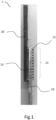
- Fig.1 shows a jointed unit 1 comprising a first component 10, preferably metallic with isotropic properties, which has a connection area 11 from which protuberances 12 extend transversally and preferably perpendicularly to this connection area.
- the first component is a metallic element e.g. a specimen wherein the connection zone 11 is a portion of surface on one end of the specimen having protuberances extending in a direction opposite to that surface.
- the shape of the first component 10 and in particular that of the protuberances 12 can be created using three-dimensional modeling software.
- the protuberances 12 can be arranged on the connection area 11 according to a pattern defined by the user, e.g.
- the jointed unit 1 includes a second component 20, preferably made of composite material such as CFRP, rigidly connected to the first component 10 by a cross-linking process of the fibers of such a composite material in the connection area 11 exploiting the construction configuration of the protuberances 12.
- the second component 20 includes first and second elongated fibrous elements 21, 22, preferably made of composite material such as for example carbon fiber strips, which are arranged in a stratified manner inside the channels 13 so that the first elongated elements 21 are arranged transversely and preferably perpendicular to the second elongated elements 22.
- the first and second elongated elements 21, 22 can respectively have longitudinally opposite ends which are arranged externally to the connection area 11, but a configuration can be provided wherein only one end of the first and/or second elongated elements protrudes from the connection area while the other remains positioned inside the latter.
- the first elongated elements 21 are each arranged in such a way as to extend along a channel transverse to the columns of protuberances of such a matrix of protuberances, e.g. along a channel formed between two rows of protuberances, while the second elongated elements 22 are each arranged in such a way as to extend along a channel transverse to the rows of protuberances of such a matrix of protuberances, e.g. along a channel formed between two columns of protuberances.
- a layer of second elongated elements 22 is positioned in the channels after a layer of first elongated elements 21 has been arranged.
- the arrangement of the first and second elongated elements 21, 22 in the respective channels 13 can be accompanied by the deposition of an epoxy resin to impregnate the fibers of the composite material to promote adhesion between the layers and at the same time favor the cross-linking process.
- a counter-mold can be created shaped so as to have projections that are inserted into the channels 13 to exert pressure on the layers of stratified fibers of the composite material. Therefore, once the desired layering level has been reached, e.g. equal to the height of the protuberances 12, the stratification of the composite material continues in such a way as to create the shape of the second component 20.
- the fibers of the composite material are made cross-linked, e.g. in an autoclave, in such a way as to rigidly connect the composite material fibers to the protuberances and form the jointed unit between the metal component and the composite material component.
- the inventors have identified that some geometries of protuberances 12, with the same dimensions of the base and height, provide the jointed unit with improved mechanical properties compared to other geometries. In particular, following FEM simulations and experimental tests, e.g.
- the protuberances 12 with a rectangular parallelepiped geometry present a profile that extends perpendicularly to the surface of the connection area 11, presenting a height greater than the long side and the short side of the base of the parallelepiped rectangle.
- the protuberances 12 with truncated pyramid geometry instead have a profile that extends from the surface of the connection area 11 perpendicularly and in a convergent manner, having a first base in contact with the surface of the connection area and a second base longitudinally opposite and preferably parallel to the first.
- CFRP-metal jointed unit were made according to the sample configuration of the ISO 22841 standard for tensile tests to evaluate the jointed unit under tensile shear.
- the jointed unit includes a first metallic component in In625 and a second component in CFRP rigidly connected to each other.
- the dimensions of the jointed unit are 110x20x6 mm.
- the dimensions of the connection area are 70x20x3 mm.
- the jointed unit area is 30x20 mm2.
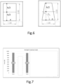
- the overall dimensions of the sample are shown in Fig. 5 .
- different geometries of protuberances 12 were made: rectangular parallelepiped, truncated pyramid and others not illustrated e.g. pyramid.
- a maximum transverse dimension e.g. in the specific case a diagonal of the value of a ⁇ 2 of the upper half-portion has a ratio between 0.8 and 1.4 with the height h.
- the matrix of protuberances 12 has a module wherein the projections themselves are spaced apart from each other by a. Thanks to the solidity e.g.
- the concentration per unit of surface area in a ratio with respect to the total volume occupied by the matrix of between 0.15 and 0.35.
- the total volume of the matrix is a polygon with a rectangular base, if the matrix is rectangular, which circumscribes all the protuberances 12 and has the same height as the protuberances themselves, which are all the same height.
- Such a volume is in the denominator and the overall volume of all the protuberances 12 contained in the volume is in the numerator. It is also possible to calculate the ratio by identifying a repetitive module of the matrix, this module including a protuberance 12 and an overall volume which, in fact, is repeated throughout the matrix.
- the bumps are arranged in a 12x8 matrix configuration on the connection area of the first component.
- the production process of the joint samples includes a first phase, in which the metal component is created through an additive printing process of LB-PBF, and a second phase in which the metal component is connected to the CFRP through the application of fibers of carbon in the channels between the protuberances and then cross-linked.
- the metal components are manufactured using the Renishaw AM 500M machine with Inconel 625. Apart from the rectangular parallelepiped and truncated pyramid geometries, all protuberances are generated without support structures during the growth of the parts, being able to support themselves. The process parameters are reported in Tab. 1, while Fig.7 shows the samples in their constructed configuration.
- the second step of the jointed unit manufacturing process is the generation of the CFRP side.
- the forming process comprises the simultaneous co-polymerization of the CFRP with the metal protuberances. Carbon fibers are placed in the channels between the protuberances together with a two-component epoxy resin. Lamination requires the preliminary fabrication of a counter mold through which stacking the layers and guide the flow of resin where necessary. Polyvinyl alcohol release agent is used on exposed surfaces to facilitate sample removal from the die.
- the first forming operation involves positioning the carbon fibers in the channels of the protuberances in a layered manner. Next, the twisted fiber layers are stacked and impregnated with epoxy resin until the CFRP laminate thickness is 3 mm (i.e. the same thickness as the metal part of the jointed unit).
- the resin polymerization process lasts 24 hours at room temperature and pressure.
- the contours of the sample are refined to achieve nominal dimensions.
- Fig.6 shows one of the samples for each protuberance geometry.
- the "2-volume model” reproduces the nominal geometry of the two joined materials, including protrusions in 3D, wherein two volumes are used to reproduce the two materials (In625 and CFRP).
- the "3-volume mixed model” uses the mixing rule to define a third material which is a medium representing the mechanical properties of the intermediate region where the protuberances are engaged in the CFRP. The actual geometry of the protuberances is not reproduced by this model.
- the "3-volume homogenized model” begins with the identification of the RVE (representative volume element). In the present case, the RVE is associated with the single metal protuberance and the surrounding composite. The metal part is defined with isotropic properties. The composite material is defined with the orthotropic properties of the fiber-matrix composition.
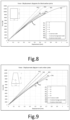
- a spacer is used to restore nominal alignment. Tests are performed in displacement control mode at a speed of 1 mm/min, while the tensile force is stored. The static force-displacement curves associated with the different metal protuberances are shown in the diagrams of Fig. 8 and 9 .
- the experimental stiffness is averaged between the interpolated curves with the least squares method applied on the experimental data.
- the 2-volume model gives an error range of -10% to 30%, the 3-volume mixed model -30% to 0%, and the 3-volume homogenized model - 10% to 10%.
- the 2-volume model provides small errors (-10% to 10%, except sample 24) for downward-oriented cuboids. Due to the large fluctuations in the displacement between 0 and 0.1 mm, the error values are overestimated. Excluding this range, the maximum error for the 3-volume mixed model is -20%, while for the 3-volume homogenized model it is +20%.
- the mixed model provides the lowest error range of -10% to 10%.
- the maximum load achieved in the experimental tests is shown in Fig. 7 .
- the maximum load corresponds to the failure of the jointed unit specimen or the onset of failure.
- the jointed units with rectangular parallelepiped protuberances show the highest maximum load (9327.32 N) although the experimental stiffness is not the highest.
- the behavior of the jointed units with truncated pyramid protuberances is comparable to that of rectangular parallelepipeds, with slight differences regarding the lower maximum load and the stiffness obtained.
- the failure modes of these jointed units are the same: the fibers break in the CFRP-metal connection area, leaving the protuberances intact. Little local delamination (cohesive failure) is observed between the layers above the jointed unit area.
- protuberances with parallelepiped and truncated pyramid geometry provide the best mechanical properties.
- the cohesive failure of the partial adhesive failure, with exposure of the carbon fibers, demonstrates the good engagement of the carbon fibers with the metal surface.
- the orientation of the protuberances aligned with or against the direction of the load shows no significant changes in the final performance of the jointed unit.
- the geometry of the pyramid protuberance shows the lowest strength and complete adhesive failure of the jointed unit, not allowing full loading of the fibers before separation of the materials.
- the jointed unit of the invention is preferably used for the creation of primary aeronautical structures e.g. wings and/or vertical aeronautical stabilizers and/or aeronautical tail rudders.
- the jointed unit of the invention is also used in boat fins, including foils.
- jointed unit of the invention is also used on board a turbine blade, e.g. wind power.
- jointed unit of the invention is also used on board wheeled land vehicles e.g. cars, motorcycles, to create devices with lift/downforce aerofoils.
Landscapes
- Engineering & Computer Science (AREA)
- Mechanical Engineering (AREA)
- Chemical & Material Sciences (AREA)
- Composite Materials (AREA)
- Crystallography & Structural Chemistry (AREA)
- Inorganic Chemistry (AREA)
- Moulding By Coating Moulds (AREA)
Applications Claiming Priority (1)
| Application Number | Priority Date | Filing Date | Title |
|---|---|---|---|
| IT102023000006393A IT202300006393A1 (it) | 2023-03-31 | 2023-03-31 | Giunzione comprendente protuberanze con geometria ottimizzata |
Publications (1)
| Publication Number | Publication Date |
|---|---|
| EP4458556A1 true EP4458556A1 (de) | 2024-11-06 |
Family
ID=86942451
Family Applications (1)
| Application Number | Title | Priority Date | Filing Date |
|---|---|---|---|
| EP24166873.0A Pending EP4458556A1 (de) | 2023-03-31 | 2024-03-27 | Zusammengefügte einheit mit strukturen mit optimierter geometrie |
Country Status (2)
| Country | Link |
|---|---|
| EP (1) | EP4458556A1 (de) |
| IT (1) | IT202300006393A1 (de) |
Citations (4)
| Publication number | Priority date | Publication date | Assignee | Title |
|---|---|---|---|---|
| US20150219133A1 (en) | 2007-03-13 | 2015-08-06 | Airbus Operations Limited | Preparation of a component for use in a joint |
| WO2017060646A1 (fr) * | 2015-10-07 | 2017-04-13 | Centre Technique Des Industries Mecaniques | Procédé de solidarisation d'un élément composite et d'un élément rigide |
| WO2018211233A1 (en) * | 2017-05-18 | 2018-11-22 | Bae Systems Plc | Fastenerless structural assembly |
| DE102019208677A1 (de) * | 2019-06-14 | 2020-12-17 | Premium Aerotec Gmbh | Verfahren zur Herstellung eines Hybridbauteils, Hybridbauteil und Luftfahrzeug |
-
2023
- 2023-03-31 IT IT102023000006393A patent/IT202300006393A1/it unknown
-
2024
- 2024-03-27 EP EP24166873.0A patent/EP4458556A1/de active Pending
Patent Citations (4)
| Publication number | Priority date | Publication date | Assignee | Title |
|---|---|---|---|---|
| US20150219133A1 (en) | 2007-03-13 | 2015-08-06 | Airbus Operations Limited | Preparation of a component for use in a joint |
| WO2017060646A1 (fr) * | 2015-10-07 | 2017-04-13 | Centre Technique Des Industries Mecaniques | Procédé de solidarisation d'un élément composite et d'un élément rigide |
| WO2018211233A1 (en) * | 2017-05-18 | 2018-11-22 | Bae Systems Plc | Fastenerless structural assembly |
| DE102019208677A1 (de) * | 2019-06-14 | 2020-12-17 | Premium Aerotec Gmbh | Verfahren zur Herstellung eines Hybridbauteils, Hybridbauteil und Luftfahrzeug |
Also Published As
| Publication number | Publication date |
|---|---|
| IT202300006393A1 (it) | 2024-10-01 |
Similar Documents
| Publication | Publication Date | Title |
|---|---|---|
| US11192322B2 (en) | 3-D honeycomb foam structure | |
| EP3305509B1 (de) | Laminiertes verbundradiusfüllmittel mit variablem radius | |
| EP2933094B1 (de) | Formherstellungverfahren für radiusfüllstoffe von verbundstrukturen | |
| Airoldi et al. | Chiral topologies for composite morphing structures–Part I: Development of a chiral rib for deformable airfoils | |
| EP1231046B1 (de) | Verfahren zur Herstellung von Elementen aus Verbundmaterial durch Co-Bonding Technik | |
| CN104669728B (zh) | 具有加强芯部的复合结构及其制造方法 | |
| Njim et al. | Analytical and numerical flexural properties of polymeric porous functionally graded (PFGM) sandwich beams | |
| US20100189566A1 (en) | Manufacturing a composite component | |
| Kaman et al. | Experimental and numerical analysis of critical buckling load of honeycomb sandwich panels | |
| US20160297509A1 (en) | Sandwich panel for an aircraft | |
| US9079365B2 (en) | Curable assembly and a filler component | |
| CN115464903B (zh) | 一种纤维增强复合材料牵引座及其制备方法、模具 | |
| EP3944944B1 (de) | Konturiertes strukturelement und herstellung des konturierten strukturelements | |
| JP4746340B2 (ja) | サンドイッチパネルの剥離進展防止構造 | |
| US20140106116A1 (en) | Composite structure core crush prevention | |
| EP4458556A1 (de) | Zusammengefügte einheit mit strukturen mit optimierter geometrie | |
| Atahan et al. | Comparative study on bending performances of 3D-printed monolithic and adhesively bonded sandwich structures with various auxetic cores: An innovative production approach | |
| CN102390129B (zh) | 一种泡沫夹层结构复合材料及其制备方法 | |
| CN111661307B (zh) | 复合结构及其成型方法 | |
| CN119249823A (zh) | 一种微米凸起结构增强金属与复材界面结合性能的有限元模拟方法 | |
| KR102079564B1 (ko) | 적층형 격자패널 및 이의 제조방법 | |
| EP2955005A1 (de) | Verbundstruktur und verfahren zur herstellung davon | |
| Johnson et al. | Behavior of three-dimensionally woven glass fiber reinforced polymeric bridge deck | |
| Falken et al. | From development of multi-material skins to morphing flight hardware production | |
| US20250367889A1 (en) | Composite radius fillers, assemblies including composite radius fillers, and systems and methods of forming the same |
Legal Events
| Date | Code | Title | Description |
|---|---|---|---|
| PUAI | Public reference made under article 153(3) epc to a published international application that has entered the european phase |
Free format text: ORIGINAL CODE: 0009012 |
|
| STAA | Information on the status of an ep patent application or granted ep patent |
Free format text: STATUS: THE APPLICATION HAS BEEN PUBLISHED |
|
| AK | Designated contracting states |
Kind code of ref document: A1 Designated state(s): AL AT BE BG CH CY CZ DE DK EE ES FI FR GB GR HR HU IE IS IT LI LT LU LV MC ME MK MT NL NO PL PT RO RS SE SI SK SM TR |
|
| STAA | Information on the status of an ep patent application or granted ep patent |
Free format text: STATUS: REQUEST FOR EXAMINATION WAS MADE |
|
| 17P | Request for examination filed |
Effective date: 20250505 |
|
| GRAP | Despatch of communication of intention to grant a patent |
Free format text: ORIGINAL CODE: EPIDOSNIGR1 |
|
| RIC1 | Information provided on ipc code assigned before grant |
Ipc: B29C 65/02 20060101AFI20260303BHEP Ipc: B29C 65/00 20060101ALI20260303BHEP Ipc: B29C 70/74 20060101ALI20260303BHEP Ipc: B29C 70/86 20060101ALI20260303BHEP Ipc: B29C 65/10 20060101ALN20260303BHEP Ipc: B29L 31/08 20060101ALN20260303BHEP Ipc: B29L 31/30 20060101ALN20260303BHEP |
|
| STAA | Information on the status of an ep patent application or granted ep patent |
Free format text: STATUS: GRANT OF PATENT IS INTENDED |
|
| RIC1 | Information provided on ipc code assigned before grant |
Ipc: B29C 65/02 20060101AFI20260317BHEP Ipc: B29C 70/74 20060101ALI20260317BHEP Ipc: B29C 70/86 20060101ALI20260317BHEP Ipc: B29C 65/10 20060101ALN20260317BHEP Ipc: B29L 31/08 20060101ALN20260317BHEP Ipc: B29L 31/30 20060101ALN20260317BHEP |