EP4458520A2 - Verfahren und vorrichtung zur bereitstellung von widerstand für benutzer einer wearable-vorrichtung - Google Patents
Verfahren und vorrichtung zur bereitstellung von widerstand für benutzer einer wearable-vorrichtung Download PDFInfo
- Publication number
- EP4458520A2 EP4458520A2 EP24200563.5A EP24200563A EP4458520A2 EP 4458520 A2 EP4458520 A2 EP 4458520A2 EP 24200563 A EP24200563 A EP 24200563A EP 4458520 A2 EP4458520 A2 EP 4458520A2
- Authority
- EP
- European Patent Office
- Prior art keywords
- motor
- user
- wearable device
- driver circuit
- motor driver
- Prior art date
- Legal status (The legal status is an assumption and is not a legal conclusion. Google has not performed a legal analysis and makes no representation as to the accuracy of the status listed.)
- Pending
Links
Images


Classifications
-
- A—HUMAN NECESSITIES
- A61—MEDICAL OR VETERINARY SCIENCE; HYGIENE
- A61H—PHYSICAL THERAPY APPARATUS, e.g. DEVICES FOR LOCATING OR STIMULATING REFLEX POINTS IN THE BODY; ARTIFICIAL RESPIRATION; MASSAGE; BATHING DEVICES FOR SPECIAL THERAPEUTIC OR HYGIENIC PURPOSES OR SPECIFIC PARTS OF THE BODY
- A61H1/00—Apparatus for passive exercising; Vibrating apparatus; Chiropractic devices, e.g. body impacting devices, external devices for briefly extending or aligning unbroken bones
- A61H1/02—Stretching or bending or torsioning apparatus for exercising
- A61H1/0237—Stretching or bending or torsioning apparatus for exercising for the lower limbs
- A61H1/024—Knee
-
- A—HUMAN NECESSITIES
- A61—MEDICAL OR VETERINARY SCIENCE; HYGIENE
- A61H—PHYSICAL THERAPY APPARATUS, e.g. DEVICES FOR LOCATING OR STIMULATING REFLEX POINTS IN THE BODY; ARTIFICIAL RESPIRATION; MASSAGE; BATHING DEVICES FOR SPECIAL THERAPEUTIC OR HYGIENIC PURPOSES OR SPECIFIC PARTS OF THE BODY
- A61H3/00—Appliances for aiding patients or disabled persons to walk about
-
- A—HUMAN NECESSITIES
- A61—MEDICAL OR VETERINARY SCIENCE; HYGIENE
- A61B—DIAGNOSIS; SURGERY; IDENTIFICATION
- A61B5/00—Measuring for diagnostic purposes; Identification of persons
- A61B5/103—Measuring devices for testing the shape, pattern, colour, size or movement of the body or parts thereof, for diagnostic purposes
- A61B5/107—Measuring physical dimensions, e.g. size of the entire body or parts thereof
- A61B5/1071—Measuring physical dimensions, e.g. size of the entire body or parts thereof measuring angles, e.g. using goniometers
-
- A—HUMAN NECESSITIES
- A61—MEDICAL OR VETERINARY SCIENCE; HYGIENE
- A61B—DIAGNOSIS; SURGERY; IDENTIFICATION
- A61B5/00—Measuring for diagnostic purposes; Identification of persons
- A61B5/103—Measuring devices for testing the shape, pattern, colour, size or movement of the body or parts thereof, for diagnostic purposes
- A61B5/11—Measuring movement of the entire body or parts thereof, e.g. head or hand tremor or mobility of a limb
- A61B5/112—Gait analysis
-
- A—HUMAN NECESSITIES
- A61—MEDICAL OR VETERINARY SCIENCE; HYGIENE
- A61B—DIAGNOSIS; SURGERY; IDENTIFICATION
- A61B5/00—Measuring for diagnostic purposes; Identification of persons
- A61B5/103—Measuring devices for testing the shape, pattern, colour, size or movement of the body or parts thereof, for diagnostic purposes
- A61B5/11—Measuring movement of the entire body or parts thereof, e.g. head or hand tremor or mobility of a limb
- A61B5/1121—Determining geometric values, e.g. centre of rotation or angular range of movement
-
- A—HUMAN NECESSITIES
- A61—MEDICAL OR VETERINARY SCIENCE; HYGIENE
- A61B—DIAGNOSIS; SURGERY; IDENTIFICATION
- A61B5/00—Measuring for diagnostic purposes; Identification of persons
- A61B5/68—Arrangements of detecting, measuring or recording means, e.g. sensors, in relation to patient
- A61B5/6801—Arrangements of detecting, measuring or recording means, e.g. sensors, in relation to patient specially adapted to be attached to or worn on the body surface
-
- A—HUMAN NECESSITIES
- A61—MEDICAL OR VETERINARY SCIENCE; HYGIENE
- A61H—PHYSICAL THERAPY APPARATUS, e.g. DEVICES FOR LOCATING OR STIMULATING REFLEX POINTS IN THE BODY; ARTIFICIAL RESPIRATION; MASSAGE; BATHING DEVICES FOR SPECIAL THERAPEUTIC OR HYGIENIC PURPOSES OR SPECIFIC PARTS OF THE BODY
- A61H1/00—Apparatus for passive exercising; Vibrating apparatus; Chiropractic devices, e.g. body impacting devices, external devices for briefly extending or aligning unbroken bones
- A61H1/02—Stretching or bending or torsioning apparatus for exercising
- A61H1/0237—Stretching or bending or torsioning apparatus for exercising for the lower limbs
- A61H1/0244—Hip
-
- A—HUMAN NECESSITIES
- A61—MEDICAL OR VETERINARY SCIENCE; HYGIENE
- A61H—PHYSICAL THERAPY APPARATUS, e.g. DEVICES FOR LOCATING OR STIMULATING REFLEX POINTS IN THE BODY; ARTIFICIAL RESPIRATION; MASSAGE; BATHING DEVICES FOR SPECIAL THERAPEUTIC OR HYGIENIC PURPOSES OR SPECIFIC PARTS OF THE BODY
- A61H1/00—Apparatus for passive exercising; Vibrating apparatus; Chiropractic devices, e.g. body impacting devices, external devices for briefly extending or aligning unbroken bones
- A61H1/02—Stretching or bending or torsioning apparatus for exercising
- A61H1/0237—Stretching or bending or torsioning apparatus for exercising for the lower limbs
- A61H1/0266—Foot
-
- A—HUMAN NECESSITIES
- A63—SPORTS; GAMES; AMUSEMENTS
- A63B—APPARATUS FOR PHYSICAL TRAINING, GYMNASTICS, SWIMMING, CLIMBING, OR FENCING; BALL GAMES; TRAINING EQUIPMENT
- A63B21/00—Exercising apparatus for developing or strengthening the muscles or joints of the body by working against a counterforce, with or without measuring devices
- A63B21/00181—Exercising apparatus for developing or strengthening the muscles or joints of the body by working against a counterforce, with or without measuring devices comprising additional means assisting the user to overcome part of the resisting force, i.e. assisted-active exercising
-
- A—HUMAN NECESSITIES
- A63—SPORTS; GAMES; AMUSEMENTS
- A63B—APPARATUS FOR PHYSICAL TRAINING, GYMNASTICS, SWIMMING, CLIMBING, OR FENCING; BALL GAMES; TRAINING EQUIPMENT
- A63B21/00—Exercising apparatus for developing or strengthening the muscles or joints of the body by working against a counterforce, with or without measuring devices
- A63B21/005—Exercising apparatus for developing or strengthening the muscles or joints of the body by working against a counterforce, with or without measuring devices using electromagnetic or electric force-resisters
- A63B21/0053—Exercising apparatus for developing or strengthening the muscles or joints of the body by working against a counterforce, with or without measuring devices using electromagnetic or electric force-resisters using alternators or dynamos
- A63B21/0054—Exercising apparatus for developing or strengthening the muscles or joints of the body by working against a counterforce, with or without measuring devices using electromagnetic or electric force-resisters using alternators or dynamos for charging a battery
-
- A—HUMAN NECESSITIES
- A63—SPORTS; GAMES; AMUSEMENTS
- A63B—APPARATUS FOR PHYSICAL TRAINING, GYMNASTICS, SWIMMING, CLIMBING, OR FENCING; BALL GAMES; TRAINING EQUIPMENT
- A63B21/00—Exercising apparatus for developing or strengthening the muscles or joints of the body by working against a counterforce, with or without measuring devices
- A63B21/005—Exercising apparatus for developing or strengthening the muscles or joints of the body by working against a counterforce, with or without measuring devices using electromagnetic or electric force-resisters
- A63B21/0058—Exercising apparatus for developing or strengthening the muscles or joints of the body by working against a counterforce, with or without measuring devices using electromagnetic or electric force-resisters using motors
- A63B21/0059—Exercising apparatus for developing or strengthening the muscles or joints of the body by working against a counterforce, with or without measuring devices using electromagnetic or electric force-resisters using motors using a frequency controlled AC motor
-
- A—HUMAN NECESSITIES
- A63—SPORTS; GAMES; AMUSEMENTS
- A63B—APPARATUS FOR PHYSICAL TRAINING, GYMNASTICS, SWIMMING, CLIMBING, OR FENCING; BALL GAMES; TRAINING EQUIPMENT
- A63B21/00—Exercising apparatus for developing or strengthening the muscles or joints of the body by working against a counterforce, with or without measuring devices
- A63B21/40—Interfaces with the user related to strength training; Details thereof
- A63B21/4001—Arrangements for attaching the exercising apparatus to the user's body, e.g. belts, shoes or gloves specially adapted therefor
- A63B21/4009—Arrangements for attaching the exercising apparatus to the user's body, e.g. belts, shoes or gloves specially adapted therefor to the waist
-
- A—HUMAN NECESSITIES
- A63—SPORTS; GAMES; AMUSEMENTS
- A63B—APPARATUS FOR PHYSICAL TRAINING, GYMNASTICS, SWIMMING, CLIMBING, OR FENCING; BALL GAMES; TRAINING EQUIPMENT
- A63B23/00—Exercising apparatus specially adapted for particular parts of the body
- A63B23/035—Exercising apparatus specially adapted for particular parts of the body for limbs, i.e. upper or lower limbs, e.g. simultaneously
- A63B23/04—Exercising apparatus specially adapted for particular parts of the body for limbs, i.e. upper or lower limbs, e.g. simultaneously for lower limbs
-
- A—HUMAN NECESSITIES
- A63—SPORTS; GAMES; AMUSEMENTS
- A63B—APPARATUS FOR PHYSICAL TRAINING, GYMNASTICS, SWIMMING, CLIMBING, OR FENCING; BALL GAMES; TRAINING EQUIPMENT
- A63B24/00—Electric or electronic controls for exercising apparatus of preceding groups; Controlling or monitoring of exercises, sportive games, training or athletic performances
- A63B24/0062—Monitoring athletic performances, e.g. for determining the work of a user on an exercise apparatus, the completed jogging or cycling distance
-
- A—HUMAN NECESSITIES
- A63—SPORTS; GAMES; AMUSEMENTS
- A63B—APPARATUS FOR PHYSICAL TRAINING, GYMNASTICS, SWIMMING, CLIMBING, OR FENCING; BALL GAMES; TRAINING EQUIPMENT
- A63B24/00—Electric or electronic controls for exercising apparatus of preceding groups; Controlling or monitoring of exercises, sportive games, training or athletic performances
- A63B24/0087—Electric or electronic controls for exercising apparatus of groups A63B21/00 - A63B23/00, e.g. controlling load
-
- B—PERFORMING OPERATIONS; TRANSPORTING
- B25—HAND TOOLS; PORTABLE POWER-DRIVEN TOOLS; MANIPULATORS
- B25J—MANIPULATORS; CHAMBERS PROVIDED WITH MANIPULATION DEVICES
- B25J9/00—Programme-controlled manipulators
- B25J9/0006—Exoskeletons, i.e. resembling a human figure
-
- H—ELECTRICITY
- H02—GENERATION; CONVERSION OR DISTRIBUTION OF ELECTRIC POWER
- H02P—CONTROL OR REGULATION OF ELECTRIC MOTORS, ELECTRIC GENERATORS OR DYNAMO-ELECTRIC CONVERTERS; CONTROLLING TRANSFORMERS, REACTORS OR CHOKE COILS
- H02P27/00—Arrangements or methods for the control of AC motors characterised by the kind of supply voltage
- H02P27/04—Arrangements or methods for the control of AC motors characterised by the kind of supply voltage using variable-frequency supply voltage, e.g. inverter or converter supply voltage
- H02P27/06—Arrangements or methods for the control of AC motors characterised by the kind of supply voltage using variable-frequency supply voltage, e.g. inverter or converter supply voltage using DC to AC converters or inverters
-
- A—HUMAN NECESSITIES
- A61—MEDICAL OR VETERINARY SCIENCE; HYGIENE
- A61H—PHYSICAL THERAPY APPARATUS, e.g. DEVICES FOR LOCATING OR STIMULATING REFLEX POINTS IN THE BODY; ARTIFICIAL RESPIRATION; MASSAGE; BATHING DEVICES FOR SPECIAL THERAPEUTIC OR HYGIENIC PURPOSES OR SPECIFIC PARTS OF THE BODY
- A61H2201/00—Characteristics of apparatus not provided for in the preceding codes
- A61H2201/12—Driving means
- A61H2201/1207—Driving means with electric or magnetic drive
- A61H2201/1215—Rotary drive
-
- A—HUMAN NECESSITIES
- A61—MEDICAL OR VETERINARY SCIENCE; HYGIENE
- A61H—PHYSICAL THERAPY APPARATUS, e.g. DEVICES FOR LOCATING OR STIMULATING REFLEX POINTS IN THE BODY; ARTIFICIAL RESPIRATION; MASSAGE; BATHING DEVICES FOR SPECIAL THERAPEUTIC OR HYGIENIC PURPOSES OR SPECIFIC PARTS OF THE BODY
- A61H2201/00—Characteristics of apparatus not provided for in the preceding codes
- A61H2201/12—Driving means
- A61H2201/1253—Driving means driven by a human being, e.g. hand driven
- A61H2201/1261—Driving means driven by a human being, e.g. hand driven combined with active exercising of the patient
-
- A—HUMAN NECESSITIES
- A61—MEDICAL OR VETERINARY SCIENCE; HYGIENE
- A61H—PHYSICAL THERAPY APPARATUS, e.g. DEVICES FOR LOCATING OR STIMULATING REFLEX POINTS IN THE BODY; ARTIFICIAL RESPIRATION; MASSAGE; BATHING DEVICES FOR SPECIAL THERAPEUTIC OR HYGIENIC PURPOSES OR SPECIFIC PARTS OF THE BODY
- A61H2201/00—Characteristics of apparatus not provided for in the preceding codes
- A61H2201/16—Physical interface with patient
- A61H2201/1602—Physical interface with patient kind of interface, e.g. head rest, knee support or lumbar support
- A61H2201/164—Feet or leg, e.g. pedal
-
- A—HUMAN NECESSITIES
- A61—MEDICAL OR VETERINARY SCIENCE; HYGIENE
- A61H—PHYSICAL THERAPY APPARATUS, e.g. DEVICES FOR LOCATING OR STIMULATING REFLEX POINTS IN THE BODY; ARTIFICIAL RESPIRATION; MASSAGE; BATHING DEVICES FOR SPECIAL THERAPEUTIC OR HYGIENIC PURPOSES OR SPECIFIC PARTS OF THE BODY
- A61H2201/00—Characteristics of apparatus not provided for in the preceding codes
- A61H2201/16—Physical interface with patient
- A61H2201/1602—Physical interface with patient kind of interface, e.g. head rest, knee support or lumbar support
- A61H2201/165—Wearable interfaces
-
- A—HUMAN NECESSITIES
- A61—MEDICAL OR VETERINARY SCIENCE; HYGIENE
- A61H—PHYSICAL THERAPY APPARATUS, e.g. DEVICES FOR LOCATING OR STIMULATING REFLEX POINTS IN THE BODY; ARTIFICIAL RESPIRATION; MASSAGE; BATHING DEVICES FOR SPECIAL THERAPEUTIC OR HYGIENIC PURPOSES OR SPECIFIC PARTS OF THE BODY
- A61H2201/00—Characteristics of apparatus not provided for in the preceding codes
- A61H2201/50—Control means thereof
- A61H2201/5023—Interfaces to the user
- A61H2201/5035—Several programs selectable
-
- A—HUMAN NECESSITIES
- A61—MEDICAL OR VETERINARY SCIENCE; HYGIENE
- A61H—PHYSICAL THERAPY APPARATUS, e.g. DEVICES FOR LOCATING OR STIMULATING REFLEX POINTS IN THE BODY; ARTIFICIAL RESPIRATION; MASSAGE; BATHING DEVICES FOR SPECIAL THERAPEUTIC OR HYGIENIC PURPOSES OR SPECIFIC PARTS OF THE BODY
- A61H2201/00—Characteristics of apparatus not provided for in the preceding codes
- A61H2201/50—Control means thereof
- A61H2201/5023—Interfaces to the user
- A61H2201/5043—Displays
-
- A—HUMAN NECESSITIES
- A61—MEDICAL OR VETERINARY SCIENCE; HYGIENE
- A61H—PHYSICAL THERAPY APPARATUS, e.g. DEVICES FOR LOCATING OR STIMULATING REFLEX POINTS IN THE BODY; ARTIFICIAL RESPIRATION; MASSAGE; BATHING DEVICES FOR SPECIAL THERAPEUTIC OR HYGIENIC PURPOSES OR SPECIFIC PARTS OF THE BODY
- A61H2201/00—Characteristics of apparatus not provided for in the preceding codes
- A61H2201/50—Control means thereof
- A61H2201/5058—Sensors or detectors
- A61H2201/5069—Angle sensors
-
- A—HUMAN NECESSITIES
- A61—MEDICAL OR VETERINARY SCIENCE; HYGIENE
- A61H—PHYSICAL THERAPY APPARATUS, e.g. DEVICES FOR LOCATING OR STIMULATING REFLEX POINTS IN THE BODY; ARTIFICIAL RESPIRATION; MASSAGE; BATHING DEVICES FOR SPECIAL THERAPEUTIC OR HYGIENIC PURPOSES OR SPECIFIC PARTS OF THE BODY
- A61H2230/00—Measuring physical parameters of the user
- A61H2230/60—Muscle strain, i.e. measured on the user, e.g. Electromyography [EMG]
- A61H2230/605—Muscle strain, i.e. measured on the user, e.g. Electromyography [EMG] used as a control parameter for the apparatus
-
- A—HUMAN NECESSITIES
- A61—MEDICAL OR VETERINARY SCIENCE; HYGIENE
- A61H—PHYSICAL THERAPY APPARATUS, e.g. DEVICES FOR LOCATING OR STIMULATING REFLEX POINTS IN THE BODY; ARTIFICIAL RESPIRATION; MASSAGE; BATHING DEVICES FOR SPECIAL THERAPEUTIC OR HYGIENIC PURPOSES OR SPECIFIC PARTS OF THE BODY
- A61H2230/00—Measuring physical parameters of the user
- A61H2230/62—Posture
- A61H2230/625—Posture used as a control parameter for the apparatus
-
- A—HUMAN NECESSITIES
- A63—SPORTS; GAMES; AMUSEMENTS
- A63B—APPARATUS FOR PHYSICAL TRAINING, GYMNASTICS, SWIMMING, CLIMBING, OR FENCING; BALL GAMES; TRAINING EQUIPMENT
- A63B24/00—Electric or electronic controls for exercising apparatus of preceding groups; Controlling or monitoring of exercises, sportive games, training or athletic performances
- A63B24/0087—Electric or electronic controls for exercising apparatus of groups A63B21/00 - A63B23/00, e.g. controlling load
- A63B2024/0093—Electric or electronic controls for exercising apparatus of groups A63B21/00 - A63B23/00, e.g. controlling load the load of the exercise apparatus being controlled by performance parameters, e.g. distance or speed
-
- A—HUMAN NECESSITIES
- A63—SPORTS; GAMES; AMUSEMENTS
- A63B—APPARATUS FOR PHYSICAL TRAINING, GYMNASTICS, SWIMMING, CLIMBING, OR FENCING; BALL GAMES; TRAINING EQUIPMENT
- A63B71/00—Games or sports accessories not covered in groups A63B1/00 - A63B69/00
- A63B71/06—Indicating or scoring devices for games or players, or for other sports activities
- A63B2071/0675—Input for modifying training controls during workout
- A63B2071/068—Input by voice recognition
-
- A—HUMAN NECESSITIES
- A63—SPORTS; GAMES; AMUSEMENTS
- A63B—APPARATUS FOR PHYSICAL TRAINING, GYMNASTICS, SWIMMING, CLIMBING, OR FENCING; BALL GAMES; TRAINING EQUIPMENT
- A63B21/00—Exercising apparatus for developing or strengthening the muscles or joints of the body by working against a counterforce, with or without measuring devices
- A63B21/40—Interfaces with the user related to strength training; Details thereof
- A63B21/4001—Arrangements for attaching the exercising apparatus to the user's body, e.g. belts, shoes or gloves specially adapted therefor
- A63B21/4011—Arrangements for attaching the exercising apparatus to the user's body, e.g. belts, shoes or gloves specially adapted therefor to the lower limbs
-
- A—HUMAN NECESSITIES
- A63—SPORTS; GAMES; AMUSEMENTS
- A63B—APPARATUS FOR PHYSICAL TRAINING, GYMNASTICS, SWIMMING, CLIMBING, OR FENCING; BALL GAMES; TRAINING EQUIPMENT
- A63B21/00—Exercising apparatus for developing or strengthening the muscles or joints of the body by working against a counterforce, with or without measuring devices
- A63B21/40—Interfaces with the user related to strength training; Details thereof
- A63B21/4023—Interfaces with the user related to strength training; Details thereof the user operating the resistance directly, without additional interface
- A63B21/4025—Resistance devices worn on the user's body
-
- A—HUMAN NECESSITIES
- A63—SPORTS; GAMES; AMUSEMENTS
- A63B—APPARATUS FOR PHYSICAL TRAINING, GYMNASTICS, SWIMMING, CLIMBING, OR FENCING; BALL GAMES; TRAINING EQUIPMENT
- A63B2220/00—Measuring of physical parameters relating to sporting activity
- A63B2220/20—Distances or displacements
- A63B2220/24—Angular displacement
-
- A—HUMAN NECESSITIES
- A63—SPORTS; GAMES; AMUSEMENTS
- A63B—APPARATUS FOR PHYSICAL TRAINING, GYMNASTICS, SWIMMING, CLIMBING, OR FENCING; BALL GAMES; TRAINING EQUIPMENT
- A63B2220/00—Measuring of physical parameters relating to sporting activity
- A63B2220/40—Acceleration
-
- A—HUMAN NECESSITIES
- A63—SPORTS; GAMES; AMUSEMENTS
- A63B—APPARATUS FOR PHYSICAL TRAINING, GYMNASTICS, SWIMMING, CLIMBING, OR FENCING; BALL GAMES; TRAINING EQUIPMENT
- A63B2220/00—Measuring of physical parameters relating to sporting activity
- A63B2220/50—Force related parameters
- A63B2220/51—Force
- A63B2220/52—Weight, e.g. weight distribution
-
- A—HUMAN NECESSITIES
- A63—SPORTS; GAMES; AMUSEMENTS
- A63B—APPARATUS FOR PHYSICAL TRAINING, GYMNASTICS, SWIMMING, CLIMBING, OR FENCING; BALL GAMES; TRAINING EQUIPMENT
- A63B2220/00—Measuring of physical parameters relating to sporting activity
- A63B2220/50—Force related parameters
- A63B2220/54—Torque
-
- A—HUMAN NECESSITIES
- A63—SPORTS; GAMES; AMUSEMENTS
- A63B—APPARATUS FOR PHYSICAL TRAINING, GYMNASTICS, SWIMMING, CLIMBING, OR FENCING; BALL GAMES; TRAINING EQUIPMENT
- A63B2220/00—Measuring of physical parameters relating to sporting activity
- A63B2220/62—Time or time measurement used for time reference, time stamp, master time or clock signal
-
- A—HUMAN NECESSITIES
- A63—SPORTS; GAMES; AMUSEMENTS
- A63B—APPARATUS FOR PHYSICAL TRAINING, GYMNASTICS, SWIMMING, CLIMBING, OR FENCING; BALL GAMES; TRAINING EQUIPMENT
- A63B2225/00—Miscellaneous features of sport apparatus, devices or equipment
- A63B2225/09—Adjustable dimensions
-
- A—HUMAN NECESSITIES
- A63—SPORTS; GAMES; AMUSEMENTS
- A63B—APPARATUS FOR PHYSICAL TRAINING, GYMNASTICS, SWIMMING, CLIMBING, OR FENCING; BALL GAMES; TRAINING EQUIPMENT
- A63B2225/00—Miscellaneous features of sport apparatus, devices or equipment
- A63B2225/50—Wireless data transmission, e.g. by radio transmitters or telemetry
-
- A—HUMAN NECESSITIES
- A63—SPORTS; GAMES; AMUSEMENTS
- A63B—APPARATUS FOR PHYSICAL TRAINING, GYMNASTICS, SWIMMING, CLIMBING, OR FENCING; BALL GAMES; TRAINING EQUIPMENT
- A63B2225/00—Miscellaneous features of sport apparatus, devices or equipment
- A63B2225/74—Miscellaneous features of sport apparatus, devices or equipment with powered illuminating means, e.g. lights
-
- A—HUMAN NECESSITIES
- A63—SPORTS; GAMES; AMUSEMENTS
- A63B—APPARATUS FOR PHYSICAL TRAINING, GYMNASTICS, SWIMMING, CLIMBING, OR FENCING; BALL GAMES; TRAINING EQUIPMENT
- A63B23/00—Exercising apparatus specially adapted for particular parts of the body
- A63B23/035—Exercising apparatus specially adapted for particular parts of the body for limbs, i.e. upper or lower limbs, e.g. simultaneously
- A63B23/03516—For both arms together or both legs together; Aspects related to the co-ordination between right and left side limbs of a user
-
- A—HUMAN NECESSITIES
- A63—SPORTS; GAMES; AMUSEMENTS
- A63B—APPARATUS FOR PHYSICAL TRAINING, GYMNASTICS, SWIMMING, CLIMBING, OR FENCING; BALL GAMES; TRAINING EQUIPMENT
- A63B23/00—Exercising apparatus specially adapted for particular parts of the body
- A63B23/035—Exercising apparatus specially adapted for particular parts of the body for limbs, i.e. upper or lower limbs, e.g. simultaneously
- A63B23/04—Exercising apparatus specially adapted for particular parts of the body for limbs, i.e. upper or lower limbs, e.g. simultaneously for lower limbs
- A63B23/0482—Exercising apparatus specially adapted for particular parts of the body for limbs, i.e. upper or lower limbs, e.g. simultaneously for lower limbs primarily by articulating the hip joints
-
- A—HUMAN NECESSITIES
- A63—SPORTS; GAMES; AMUSEMENTS
- A63B—APPARATUS FOR PHYSICAL TRAINING, GYMNASTICS, SWIMMING, CLIMBING, OR FENCING; BALL GAMES; TRAINING EQUIPMENT
- A63B24/00—Electric or electronic controls for exercising apparatus of preceding groups; Controlling or monitoring of exercises, sportive games, training or athletic performances
- A63B24/0075—Means for generating exercise programs or schemes, e.g. computerized virtual trainer, e.g. using expert databases
-
- H—ELECTRICITY
- H02—GENERATION; CONVERSION OR DISTRIBUTION OF ELECTRIC POWER
- H02J—CIRCUIT ARRANGEMENTS OR SYSTEMS FOR SUPPLYING OR DISTRIBUTING ELECTRIC POWER; SYSTEMS FOR STORING ELECTRIC ENERGY
- H02J2310/00—The network for supplying or distributing electric power characterised by its spatial reach or by the load
- H02J2310/10—The network having a local or delimited stationary reach
- H02J2310/20—The network being internal to a load
- H02J2310/23—The load being a medical device, a medical implant, or a life supporting device
-
- H—ELECTRICITY
- H02—GENERATION; CONVERSION OR DISTRIBUTION OF ELECTRIC POWER
- H02J—CIRCUIT ARRANGEMENTS OR SYSTEMS FOR SUPPLYING OR DISTRIBUTING ELECTRIC POWER; SYSTEMS FOR STORING ELECTRIC ENERGY
- H02J7/00—Circuit arrangements for charging or depolarising batteries or for supplying loads from batteries
- H02J7/32—Circuit arrangements for charging or depolarising batteries or for supplying loads from batteries for charging batteries from a charging set comprising a non-electric prime mover rotating at constant speed
-
- H—ELECTRICITY
- H02—GENERATION; CONVERSION OR DISTRIBUTION OF ELECTRIC POWER
- H02P—CONTROL OR REGULATION OF ELECTRIC MOTORS, ELECTRIC GENERATORS OR DYNAMO-ELECTRIC CONVERTERS; CONTROLLING TRANSFORMERS, REACTORS OR CHOKE COILS
- H02P27/00—Arrangements or methods for the control of AC motors characterised by the kind of supply voltage
- H02P27/04—Arrangements or methods for the control of AC motors characterised by the kind of supply voltage using variable-frequency supply voltage, e.g. inverter or converter supply voltage
- H02P27/06—Arrangements or methods for the control of AC motors characterised by the kind of supply voltage using variable-frequency supply voltage, e.g. inverter or converter supply voltage using DC to AC converters or inverters
- H02P27/08—Arrangements or methods for the control of AC motors characterised by the kind of supply voltage using variable-frequency supply voltage, e.g. inverter or converter supply voltage using DC to AC converters or inverters with pulse width modulation
-
- H—ELECTRICITY
- H02—GENERATION; CONVERSION OR DISTRIBUTION OF ELECTRIC POWER
- H02P—CONTROL OR REGULATION OF ELECTRIC MOTORS, ELECTRIC GENERATORS OR DYNAMO-ELECTRIC CONVERTERS; CONTROLLING TRANSFORMERS, REACTORS OR CHOKE COILS
- H02P7/00—Arrangements for regulating or controlling the speed or torque of electric DC motors
Definitions
- At least one example embodiment relates to a method and/or device for providing resistance to a user of a wearable device.
- at least one example embodiment relates to a method and/or device for providing resistance to a user of a wearable device without providing energy to a motor of the wearable device.
- Some example embodiments relate to a method of operating a wearable device to provide a resistance force to a user.
- the method includes measuring, via a sensor, a first angle of a first joint of the user, determining a resistance level to apply to the first joint based on the first angle, determining a connection ratio between a connected time for which a motor driver circuit electrically connected to a motor of the wearable device is controlled to be a closed loop and a disconnected time for which the motor driver circuit is controlled to be an open loop, based on the resistance level, and controlling the motor through the motor driver circuit based on the connection ratio.
- the motor driver circuit may include at least one switch configured to be controlled based on the connection ratio.
- connection ratio may be represented by a pulse width modulation (PWM).
- PWM pulse width modulation
- the resistance level to be provided to the user may be adjusted based on the connection ratio such that as the connected time for which the motor driver circuit is controlled to be the closed loop increases, the resistance force may increase.
- the motor driver circuit when the motor driver circuit is controlled to be the closed loop, the motor may operate as a generator with respect to an external force by the user.
- the method may further include charging a battery of the wearable device based on energy generated by the generator.
- the method may further include receiving, from the user, an instruction to set an operation mode of the wearable device to an exercise mode.
- the motor when the exercise mode is set, the motor may not be provided with energy from the battery of the wearable device.
- the method may further include receiving, from the user, an instruction to set an operation mode of the wearable device to an assistance mode, calculating an assistance torque value to apply to the first joint based on the first angle in response to the assistance mode being received, and providing an assistance force to the user by controlling the motor based on the assistance torque value.
- Some example embodiments relate to a wearable device configured to provide a resistance force to a user.
- the wearable device includes a memory configured to store a program that includes instructions to provide the resistance force to the user, a sensor configured to measure a first angle of a first joint of the user, a motor driver circuit, a motor electrically connected to the motor driver circuit, and a processor configured to execute the program to measure, via the sensor, the first angle of the first joint of the user, determine a resistance level to apply to the first joint based on the first angle, determine a connection ratio between a connected time for which the motor driver circuit is controlled to be a closed loop and a disconnected time for which the motor driver circuit is controlled to be an open loop based on the resistance level, and control the motor through the motor driver circuit based on the connection ratio.
- the motor driver circuit may include at least one switch configured to be controlled based on the connection ratio.
- connection ratio may be represented by a PWM, and the resistance force to be provided to the user may be adjusted based on the connection ratio such that, as the connected time for which the motor driver circuit is controlled to be the closed loop increases, the resistance force may increase.
- the motor driver circuit when the motor driver circuit is controlled to be the closed loop, the motor may operate as a generator with respect to an external force by the user.
- the processor when the motor operates as the generator, the processor is further configured to charge a battery of the wearable device based on energy generated by the generator.
- the processor is further configured to receive, from the user, an instruction to set an operation mode of the wearable device to an exercise mode, and determine the resistance level to apply to the first joint based on the exercise mode and the first angle.
- the motor when the exercise mode is set, the motor may not be provided with energy from the battery by the wearable device.
- the processor is further configured to, receive, from the user, an instruction to set an operation mode of the wearable device to an assistance mode, calculate an assistance torque value to apply to the first joint based on the first angle in response to the assistance mode being received, and provide an assistance force to the user by controlling the motor based on the assistance torque value.
- first, second, A, B, (a), (b), and the like may be used herein to describe components.
- Each of these terminologies is not used to define an essence, order or sequence of a corresponding component but used merely to distinguish the corresponding component from other component(s). It should be noted that if it is described in the specification that one component is “connected,” “coupled,” or “joined” to another component, a third component may be “connected,” “coupled,” and “joined” between the first and second components, although the first component may be directly connected, coupled or joined to the second component.
- FIGS. 1A through 1D are diagrams illustrating an example of a wearable device according to at least one example embodiment.
- a wearable device 100 may be worn on a user and configured to assist the user in walking more readily.
- the wearable device 100 may be a device that assists the user in walking.
- the wearable device 100 may also be an exercise device that provides an exercise function by providing the user with a resistance force to assist the user in doing an exercise.
- the resistance force to be provided to the user may not be a force that is actively applied to the user, for example, a force output by a device such as a motor, but a force that hinders a movement of the user, for example, a force acting in a direction opposite to a direction in which the user moves. That is, the resistance force may also be referred to as an exercise load.
- FIGS. 1A and 1B illustrate an example of a hip-type wearable device
- a type of a wearable device is not limited to the illustrated hip type, and the wearable device may be provided in a type that supports a whole lower body, supports a portion of the lower body, for example, a portion of the lower body up to a knee and a portion of the lower body up to an ankle, or supports a whole body.
- example embodiments to be described hereinafter with reference to FIGS. 1A and 1B are applicable to a hip-type wearable device, for example, the wearable device 100, the example embodiments are not limited to the hip-type wearable device, but applicable to all types of wearable devices.
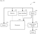
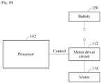
- the wearable device 100 includes a driver 110, a sensor 120, an inertial measurement unit (IMU) 130, a controller 140, and a battery 150.
- IMU inertial measurement unit
- the driver 110 includes a motor 114 and a motor driver circuit 112 configured to drive the motor 114.
- the sensor 120 includes at least one sensor 121.
- the controller 140 includes a processor 142, a memory 144, and an input interface 146.
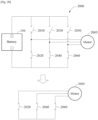
- a single sensor 121, a single motor driver circuit 112, and a single motor 114 are illustrated in FIG. 1C , examples are not limited thereto.
- a wearable device 100-1 may include a plurality of sensors 121 and 121-1, a plurality of motor driver circuits 112 and 112-1, and a plurality of motors 114 and 114-1, as illustrated in FIG. 1D .
- the wearable device 100 may include a plurality of processors. The number of motor driver circuits, the number of motors, or the number of processors may vary according to a body part on which the wearable device 100 is to be worn.
- the following descriptions of the sensor 121, the motor driver circuit 112, and the motor 114 are also applicable to the sensor 121-1, the motor driver circuit 112-1, and the motor 114-1 illustrated in FIG. 1D .
- the driver 110 may drive hip joints of the user wearing the wearable device 100.
- the driver 110 may be disposed in a portion of a right hip of the user and/or a portion of a left hip of the user.
- the driver 110 may be additionally disposed in a portion of knees of the user and a portion of ankles of the user.
- the driver 110 includes the motor 114 configured to generate a rotational torque and the motor driver circuit 112 configured to drive the motor 114.
- the sensor 120 may measure a hip joint angle of the user when the user walks.
- information associated with the hip joint angle sensed by the sensor 120 may include an angle of a right hip joint, an angle of a left hip joint, a difference between the angle of the right hip joint and the angle of the left hip joint, and/or a hip joint movement direction.
- the sensor 121 may be disposed in the driver 110. Based on a position of the sensor 121, the sensor 120 may additionally measure a knee angle of the user and an ankle angle of the user.
- the senor 120 may include a potentiometer.
- the potentiometer may sense an R-axis joint angle and an L-axis joint angle, and an R-axis joint angular velocity and an L-axis joint angular velocity, based on a walking motion of the user.
- the IMU 130 may measure acceleration information and pose information when the user walks. For example, the IMU 130 may sense an X-axis acceleration, a Y-axis acceleration, and a Z-axis acceleration, and an X-axis angular velocity, a Y-axis angular velocity, and a Z-axis angular velocity, based on a walking motion of the user.
- the wearable device 100 may detect a point at which a foot of the user lands based on the acceleration information measured by the IMU 130.
- a pressure sensor (not shown) may be disposed on a sole of a foot of the user and detect a point in time at which the foot of the user lands.
- the wearable device 100 may include other sensors configured to sense a change in a quantity of motion of the user or a change in biosignal based on a walking motion of the user.
- the sensors may include an electromyogram (EMG) sensor, for example.
- EMG electromyogram
- the processor 142 of the controller 140 may control the driver 110 to provide a resistance force to the user.
- the driver 110 may provide the resistance force to the user through back-drivability of the motor 114 without outputting a torque to the user.
- back-drivability of the motor 114 may indicate reactivity of a rotation axis of the motor 114 in response to an external force.
- high back-drivability of the motor 114 may indicate readily responding to an external force applied to the rotation axis of the motor 114, that is, the rotation axis of the motor 114 rotates readily.
- a degree of a rotation of the rotation axis of the motor 114 may directly vary depending on a level of back-drivability.
- a method of providing a resistance force to a user will be described in detail hereinafter with reference to FIGS. 7 through 21 .
- the processor 142 of the controller 140 may control the driver 110 to output a torque, for example, an assistance torque, to assist the user in walking.
- a torque for example, an assistance torque
- the driver 110 may be provided as two drivers for the right hip and the left hip, respectively, in the wearable device 100 of the hip type, and the controller 140 may output a control signal for controlling the driver 110 such that the torque is generated.
- the driver 110 may generate the torque based on the control signal output by the controller 140.
- a torque value used to generate the torque may be set externally or set by the controller 140.
- the controller 140 may use a magnitude of a current with respect to a signal transmitted to the driver 110. That is, as the magnitude of the current received by the driver 110 increases, the torque value may increase.
- the battery 150 may provide power to components of the wearable device 100.
- a circuit for example, a power management integrated circuit (PMIC) that is configured to convert power of the battery 150 to an operating voltage of each of the components of the wearable device 100 and then provide the power to the components.
- PMIC power management integrated circuit
- the battery 150 may provide or not provide power to the motor 114 based on an operation mode of the wearable device 100. That is, the battery 150 may provide power to the motor 114 in an assistance mode, and not provide power to the motor 114 in an exercise mode. Thus, less power may be consumed in the battery 150 in the exercise mode, and thus an available time for using the wearable device 100 may increase.
- FIG. 2 is a diagram illustrating an example of a wearable device communicating with an electronic device according to at least one example embodiment.
- the wearable device 100 may communicate with an electronic device 200.
- the electronic device 200 may include, for example, a smartphone, a tablet personal computer (PC), a smart watch, eyeglasses, and the like, but examples are not limited thereto.
- the electronic device 200 may be an electronic device associated with a user of the wearable device 100.
- the user may do exercise together with a trainer with the wearable device 100 on.
- the electronic device 200 may be an electronic device associated with the trainer.
- the wearable device 100 and the electronic device 200 may communicate with each other via a server (not shown) using a short-range wireless communication method or a cellular mobile communication method.
- the electronic device 200 may display, on a display 200-1, a user interface (UI) for controlling an operation of the wearable device 100.
- UI user interface
- the UI may include at least one softkey that enables the user to control the wearable device 100.
- the user or the trainer may input a control instruction for controlling an operation of the wearable device 100 through the UI on the display 200-1 of the electronic device 200.
- the electronic device 200 may transmit the control instruction to the wearable device 100.
- the wearable device 100 may operate according to the received control instruction, and transmit a control result to the electronic device 200.
- the electronic device 200 may display a message indicating control completion on the display 200-1 of the electronic device 200.
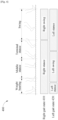
- FIG. 3 is a diagram illustrating an example of a gait state according to at least one example embodiment.
- a gait state or a gait phase of one of legs of a user of a wearable device may be defined (or, alternatively, predefined).
- the gait state may include a stance and a swing.
- the swing indicates a state in which a foot is away from the ground.
- a gait state of a left leg of the user may include a left stance (LSt) and a left swing (LSw)
- a gait state of a right leg of the user may include a right stance (RSt) and a right swing (RSw).
- a gait cycle of such gait states or phases may be mapped in advance. For example, 0% of the gait cycle may be mapped at a point in time at which a stance starts, 60% of the gait cycle may be mapped at a point in time at which a swing starts, and 100% of the gait cycle may be mapped at a point in time immediately before a next stance starts.
- FSM finite-state machine
- the stance and the swing may be more elaborately classified into a plurality of states.
- the stance may be classified into, for example, an initial contact, a weight bearing, a middle stance, a terminal stance, and a pre-swing.
- the swing may be classified into, for example, an initial swing, a middle swing, and a terminal swing.
- the classification of the stance and the swing is not limited to the example classification described in the foregoing, and the stance and the swing may be differently classified according to examples.
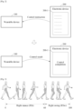
- FIG. 4 is a diagram illustrating an example of a transition in gait state according to at least one example embodiment.
- a gait state of each of both legs may include a stance and a swing, and the stance and the swing may occur alternately for walking.
- a gait state 410 of a right leg according to a change 400 in the right leg by walking may include a right stance and a right swing.
- the stance may include a weight bearing, a middle stance, and a terminal stance.
- examples are not limited to the illustrated example.
- a gait state 420 of a left leg according to a change (not shown) in the left leg with respect to the change 400 in the right leg may include a left stance and a left swing.
- a wearable device may be provided to those who may have difficulty in adjusting an angle of an ankle themselves due to reduced muscular strength of the ankle.
- the wearable device may be worn around an ankle of a user and output an assistance torque based on a value sensed in association with walking or gait of the user.
- the assistance torque may be used to adjust an angle of the ankle of the user.
- example embodiment described above relates to assisting or supporting an ankle
- example embodiment may also be similarly and substantially applied to assisting or supporting a hip joint or a knee.
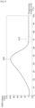
- FIG. 5 is a diagram illustrating an example of a trajectory of an ankle joint angle with respect to a gait cycle according to at least one example embodiment.
- an ankle joint angle of the user may change as shown in a trajectory 500.
- an ankle joint angle may change even in the same gait state based on a stride and a walking speed, trajectories of an ankle joint angle with respect to one gait cycle may develop in a similar pattern.
- the trajectory 500 may have an illustrated range of changes in a progression of a gait cycle. The range of changes may include weight bearing 510, middle stance 520, terminal stance 530 and swing 540.
- the illustrated trajectory 500 may not be shown in an ankle joint angle of a leg of a patient who may experience inconvenience with the leg.
- the ankle joint angle of the leg from which the patient may experience inconvenience is adjusted such that the ankle joint angle of the leg has the trajectory 500, a gait mechanism of the patient may be improved.
- FIG. 6 is a diagram illustrating an example of a trajectory of an ankle torque with respect to a gait cycle according to at least one example embodiment.
- FIG. 6 what is to be described hereinafter with reference to FIG. 6 may be applied to a case in which the wearable device 100 operates in an assistance mode in which the wearable device 100 assists a user wearing the wearable device 100 in walking.
- a case in which the wearable device 100 operates in an exercise mode will be described in detail with reference to FIGS. 7 through 21 .
- an ankle torque to be output by an ankle joint of the user may change as shown in a trajectory 600.
- a positive value of the ankle torque may increase an ankle joint angle, for example, enabling plantar flexion.
- a negative value of the ankle torque may decrease the ankle joint angle, for example, enabling dorsiflexion.
- a first portion 610 of the trajectory 600 of the ankle torque that corresponds to a segment after a push-off occurs may be an assistance torque value for the dorsiflexion to prevent a foot drop.
- the assistance torque value for the dorsiflexion may be a negative value.
- a patient who may experience inconvenience with his/her leg may not generate a sufficient assistance torque himself/herself, and thus the patient may wear a wearable device on the leg from which the patient experiences inconvenience to receive the assistance torque.
- the wearable device may output the assistance torque through a driver and adjust an ankle angle.
- the assistance torque for adjusting the ankle angle may need to be output at a desirable timing so that the user may not experience inconvenience.
- a relatively high assistance torque for increasing the ankle angle may need to be provided at a time at which the leg performs a push-off.
- the timing may be determined by directly determining a gait state of the leg from which the patient experiences inconvenience.
- the timing may be determined by indirectly determining a gait state of the leg based on a gait state of the other normal leg from which the patient does not experience inconvenience.
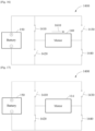
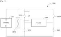
- FIGS. 7 through 10 are diagrams illustrating an example of a motor driver circuit of a wearable device according to at least one example embodiment.
- the motor driver circuit 112 is an H-bridge circuit and includes a plurality of switches, for example, a first switch 710, a second switch 720, a third switch 730, and a fourth switch 740.
- the motor driver circuit 112 is connected to the motor 114.
- a closed loop including the battery 150 may be formed.
- power may be provided to the motor 114 from the battery 150.
- the motor 114 may rotate in a first direction.
- a closed loop including the battery 150 may be formed.
- power may be provided to the motor 114 from the battery 150.
- the motor 114 may rotate in a second direction which is opposite to the first direction.
- the motor driver circuit 112 may be controlled such that a closed loop including the battery 150 is formed.
- the battery 150 may provide power to the motor 114.
- the motor 114 may rotate in a direction corresponding to a direction of a current.
- the processor 142 may control the motor driver circuit 112 such that the closed loop including the battery 150 is formed.
- the motor driver circuit 112 may also be controlled such that the battery 150 is excluded. Such an example will be described hereinafter with reference to FIGS. 9 and 10 .
- the example of controlling the motor driver circuit 112 as described hereinafter with reference to FIGS. 9 and 10 may be used when an operation mode of the wearable device 100 is an exercise mode.
- the processor 142 may block an electrical connection between the battery 150 and the motor 114 by opening the first switch 710 and the second switch 720.
- the first switch 710 and the second switch 720 may remain opened.
- a lower driver circuit including the third switch 730 and the fourth switch 740 connected to the motor 114 may only be controlled.
- the processor 142 may apply control signal 1 to the third switch 730 and apply control signal 2 to the fourth switch 740 such that a control state of the motor driver circuit 112 changes between a first control state and a second control state.
- control signal 1 and control signal 2 may be in a form of a PWM in which a high value and a low value repeatedly alternate and have a duty ratio.
- the duty ratio may indicate a connection ratio. In a case in which one period is T and a time for which a high value is maintained in one period T is t H , the duty ratio is t H /T.
- the outputting of control signals 1 and 2 by the processor 142 is described herein, examples are not limited thereto.
- the processor 142 may output a single control signal, and the output control signal may be divided by a separate circuit. Control signals obtained through the dividing may be applied to the third switch 730 and the fourth switch 740, respectively.
- a (+) terminal and a (-) terminal of the motor 114 may be connected to be in an equipotential state. That is, in the first control state, the (+) terminal and the (-) terminal of the motor 114 may be electrically connected to have the same potential or voltage.
- the motor 114 may form a closed loop with the ground without an electrical connection with the battery 150.
- the first control state may also be referred to as a closed loop state of the motor 114 free of the electrical connection with the battery 150.
- the motor 114 disposed around a corresponding joint of the user may rotate by the movement of the joint of the user.
- an electromotive force or a potential difference may occur in the motor 114.
- the terminals of the motor 114 in the first control state may be in the equipotential state, and thus a rotation resistance may be generated in the motor 114 to reduce the generated electromotive force. This rotation resistance may be provided to the user as a resistance force.
- control signals 1 and 2 are low values
- the (+) terminal and the (-) terminal of the motor 114 may be electrically opened.
- the second control state there is no electrical connection to the motor 114.
- the second control state may also be referred to as an open loop state of the motor 114.
- the motor 114 When a user moves in the second control state, the motor 114 may rotate by the movement of the user. In the second control state, the (+) terminal and the (-) terminal of the motor 114 may be electrically opened, and thus an electromotive force may not occur in the motor 114 and the resistance force may not be output. That is, back-drivability of the motor 114 may increase, and a frictional force by a gear ratio may only be felt or experienced by the user as the resistance force.
- control signals 1 and 2 may repeat according to a PWM signal, and thus the control sate of the motor driver circuit 112 may be switched repeatedly between the first control state and the second control state.
- the processor 142 may adjust a magnitude of the resistance force by controlling a duty ratio of each of control signals 1 and 2. For example, when a time for which a high value is maintained increases in a period of each of control signals 1 and 2 (that is, a time for which a low value is maintained decreases), a ratio of the motor 114 operating in the first control state in a period of each of control signals 1 and 2 may increase compared to a ratio of the motor 114 operating in the second control state in a period of each of control signals 1 and 2. Thus, an intensity of the resistance force to be output to the user may increase.
- a ratio of the motor 114 operating in the second control state in a period of each of control signals 1 and 2 may increase compared to a ratio of the motor 114 operating in the first control state in a period of each of control signals 1 and 2.
- an intensity of the resistance force to be output to the user may decrease.
- the wearable device 100 may output a resistance force without providing power of the battery 150 to the motor 114, and it is thus possible to consume less power of the battery 150 and increase an available time for using the wearable device 100.
- the motor 114 may malfunction.
- the power of the battery 150 may not be provided to the motor 114, and thus a potential malfunction of the motor 114 may be prevented and the safety of the wearable device 100 may be improved further.
- the motor driver circuit 112 may be controlled not to include the battery 150.
- the battery 150 may be electrically disconnected from the motor 114.
- the motor 114 may generate an electromotive force (in a case in which the connection state corresponds to a closed loop) by an external force or may not generate the electromotive force (in a case in which the connection state corresponds to an open loop).
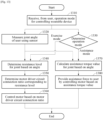
- FIG. 11 is a flowchart illustrating an example of a method of providing a resistance force according to at least one example embodiment.
- Operations 1110 through 1180 to be described hereinafter with reference to FIG. 11 may be performed by the wearable device 100.
- the wearable device 100 is described above as being worn on a lower body of a user, examples of the wearable device 100 are not limited thereto.
- the wearable device 100 may be worn on an upper body of a user.
- the wearable device 100 may be worn throughout a whole body of a user.
- the wearable device 100 receives, from a user, an operation mode that controls the wearable device 100.
- the operation mode may include an exercise mode and an assistance mode, and the received operation mode may be the exercise mode or the assistance mode.
- the user may transmit the operation mode to the wearable device 100 through a user terminal connected to the wearable device 100 through a wireless network.
- the wearable device 100 may receive the operation mode through a communication module.
- the wireless network may include, for example, a cellular network, a Bluetooth network, a WiFi network, and the like, but examples are not limited thereto.
- the user may input the operation mode through the input interface 146 of the wearable device 100.
- the input interface 146 may include, for example, a physical button for receiving an input of the user, a software button formed based on a touch panel, a display and an indicator for outputting a state of the wearable device 100, and the like.
- the indicator may be, for example, a light-emitting diode (LED), but examples are not limited thereto.
- a plurality of dynamic modes that control the wearable device 100 may be provided in advance in the wearable device 100.
- the wearable device 100 may control an operation of the wearable device 100 through a control algorithm.
- the control algorithm may be an algorithm that outputs a control value corresponding to an input including, for example, an input from the user and an input from the sensor 120, the IMU 130, and the like.
- the control algorithm may operate based on a control table indicating an output value corresponding to input values.
- the wearable device 100 may control an operation of the wearable device 100 based on a neural network corresponding to each operation mode rather than through a control algorithm.
- the neural network may be an artificial neural network, and be trained in advance through machine learning.
- the neural network may be, for example, a convolutional neural network (CNN), a recurrent neural network (RNN), a deep neural network (DNN), and a combination thereof, but examples are not limited thereto.
- the neural network may output a result for the input. For example, when an angle of a joint is input, a neural network trained with the assistance mode may determine a gait state corresponding to the angle and calculate an assistance torque value for the joint. For another example, when an angle of a joint is input, a neural network trained with the exercise mode may determine a gait state corresponding to the angle and calculate and output a resistance level for the joint. In this example, the resistance level to be calculated may vary based on an exercise level set by the user. For example, when a higher exercise level is set, a higher resistance level may be calculated.
- the wearable device 100 measures an angle of a joint of the user using the sensor 121.
- the sensor 121 may be an angle sensor, and measure an angle of at least one of a hip joint, a knee joint, or an ankle joint.
- respective angles of a plurality of joints may be measured.
- the angles of the joints that are simultaneously measured may form a joint angle set with respect to a certain time.
- the joint angle set may be used to determine a level of a gait cycle of the user. For example, a leg pose of the user may be determined based on a hip joint angle, a knee joint angle, and an ankle joint angle.
- the joint angle set may additionally include an angular acceleration calculated based on a variation in the same joint angle.
- hip joint the knee joint, and the ankle joint are described herein as examples, the foregoing description may also be applied to other joints including, for example, a shoulder joint, an elbow joint, and a wrist joint.
- operation 1120 is illustrated as being performed between operations 1110 and 1130, operation 1120 may be performed continuously as long as power is provided to the sensor 121.
- the sensor 121 may generate data including, for example, a joint angle, on a preset period. That is, the joint angle may be measured successively and continuously.
- the processor 142 of the wearable device 100 determines whether the operation mode is the exercise mode or the assistance mode.
- a resistance force may be provided to the user.
- an assistance force may be provided to the user.
- operations 1140 through 1160 may be performed.
- operations 1170 and 1180 may be performed.
- operation mode is determined in operation 1130
- whether the operation mode is the assistance mode may be determined in operation 1130 and then whether the operation mode is the exercise mode may be determined when the operation mode is determined not to be the assistance mode.
- whether the operation mode is the exercise mode may be determined in operation 1130 and then whether the operation mode is the assistance mode may be determined when the operation mode is determined not to be the exercise mode.
- the exercise mode when the user walks, the exercise mode may be applied in the entire gait state, or selectively applied in a certain gait state.
- the exercise mode may be applied only in a swing state between a stance state and the swing state as the user chooses.
- the angle of the joint of the user may be used.
- the processor 142 of the wearable device 100 determines the resistance level for the joint based on the measured angle of the joint. For example, through the control algorithm, a resistance level for an input of a joint angle may be determined. For another example, a resistance level may be output by inputting a joint angle to a neural network determined based on the operation mode.
- the resistance level refers to a level or magnitude of a resistance force the user may feel or experience. For example, when the user desires to receive the same resistance force for an entire gait motion (or a running motion), the same resistance level may be determined for the entire gait motion. For another example, when the user desires to receive a different resistance force for a certain state or phase of a gait mechanism (e.g., a swing state), a level of a gait cycle of the user may be determined based on a joint angle (e.g., a joint angle set) and a resistance level corresponding to the determined level of the gait cycle may be determined. The level of the gait cycle may change in real time, and thus the resistance level to be determined may change in real time.
- a joint angle e.g., a joint angle set
- a resistance force profile generated in advance may indicate a trajectory of a resistance level with respect to an entire gait cycle. Based on the resistance force profile with respect to the entire gait cycle, a resistance level corresponding to a level of a current gait cycle may be determined.
- the resistance profile may be adjusted by the user.
- the user may adjust a resistance level of at least a portion of the resistance force profile through the input interface 146 of the wearable device 100 or a user terminal connected to the wearable device 100. That is, the user may adjust a resistance level of at least a portion of the resistance force profile to set an exercise method desired by the user.
- the resistance force profile will be described in detail with reference to FIG. 12 .
- a neural network for each operation mode may be pretrained by a manufacturer of the wearable device 100.
- the neural network may be additionally trained, for example, fine-tuned, by the user of the wearable device 100.
- the user may input feedback on a current output of the neural network to the wearable device 100, and the processor 142 may additionally train the neural network such that the feedback is reflected.
- backpropagation or reinforcement learning may be used, but examples are not limited thereto.
- the resistance level may be determined based on a position and an angle of a joint of the user.
- a target pose of a left leg of the user may be set in advance, and a resistance level may be determined based on a difference between the target pose and a current pose of the user.
- the resistance level may be determined to be small.
- the resistance level may be determined to be great.
- a maximum resistance level may be provided to the user.
- a resistance level may be greater when the user lifts the thigh higher, and the user may feel or experience a strongest resistance force from the target pose.
- a damping control technology to which a muscle model is applied may be used.
- resistance levels determined through the damping control technology change in sequential order, a sense of resistance the user may feel or experience against a change in exercise load may be reduced.
- the input stimulus signal when a stimulus signal is input to muscle, the input stimulus signal may be amplified in proportion to a force generated by the muscle (which is positive feedback), and muscular strength (or a force) amplified by the stimulus signal may have a relational expression by a length of the muscle and a contraction speed of the muscle.
- a biological muscle model e.g., a hill-type muscle model developed in medical engineering
- the muscle When the muscle is contracted most and when the muscle is stretched most, there may not be a great force. However, when the muscle has an appropriate length, the muscle may have strongest power. A force generated based on a speed at which the length of the muscle changes may be greater when the speed of the change increases.
- a relationship between the length of the muscle and the muscular strength of the muscle based on the length of the muscle may be in a form of a normal distribution.
- a relationship between the muscle stretching speed and the muscular strength of the muscle based on the muscle stretching speed may be in a form of a sigmoid.
- the user may be familiar with a change in a physical movement based on the stretching of the muscle and the magnitude of the corresponding strength or force.
- a resistance level corresponding to the magnitude of the force exhibited in response to the change in the physical movement is provided to the user, the user may also become familiar with a resistance force (or an exercise load) provided by the resistance level and a change in the resistance force based on a change in the resistance level.
- the wearable device 100 may calculate a physical movement of the user based on a position and an angle of a joint of the user.
- the processor 142 of the wearable device 100 may calculate the physical movement and the magnitude of the corresponding force by the movement, based on the position and the angle of the joint of the user, and calculate a control level based on the calculated magnitude of the force.
- the processor 142 of the wearable device 100 determines a ratio between a time for which the motor driver circuit 112 is controlled to be a closed loop and a time for which the motor driver circuit 112 is controlled to be an open loop, based on the resistance level.
- the ratio between the time for which the motor driver circuit 112 is controlled to be the closed loop and the time for which the motor driver circuit 112 is controlled to be the open loop may also be referred to as a connection ratio.
- the connection ratio of the motor driver circuit 112 corresponding to the resistance level may be determined.
- the connection ratio of the motor driver circuit 112 may indicate a ratio at which the motor driver circuit 112 is controlled to be the closed loop (e.g., the first control state) or the open loop (e.g., the second control state) while energy is controlled not to be provided to the motor 114 from the battery 150.
- the connection ratio being 0.5 may indicate that the closed loop state is controlled to be 50% and an open loop state is controlled to be 50% in a set (or, alternatively, a preset) period.
- the connection ratio may be dynamically adjusted.
- connection ratio may be implemented using a PWM.
- PWM pulse width modulator
- the connection ratio determined in operation 1150 may be represented by a PWM having a certain duty ratio.
- the PWM having the duty ratio may be set (or, alternatively, preset) such that a desired resistance force is provided to the user.
- the motor driver circuit 112 may be controlled to be the closed loop (first control state) or the open loop (second control state).
- the processor 142 may control the motor driver circuit 112 to be the closed loop or the open loop by controlling an operation of each of switches in the motor driver circuit 112 using the PWM.
- the motor 114 When the motor driver circuit 112 is the closed loop, the motor 114 may operate as a generator, and back-drivability of the motor 114 may decrease by dynamic braking. When the back-drivability decreases, a resistance force the user may feel or experience may increase. In contrast, when the motor driver circuit 112 is the open loop, the back-drivability of the motor 114 may increase, and only a frictional force by a gear ratio may be experienced by the user as a resistance force.
- a desired back-drivability may be obtained by adjusting an open-closed state ratio of the motor driver circuit 112 based on the connection ratio.
- the resistance force to be provided to the user may be adjusted by the ratio at which the motor driver circuit 112 is controlled to be the closed loop or the open loop within a uniform and repetitive time interval of the PWM, and the resistance force may increase when the ratio of the time for controlling the motor driver circuit 112 to be the closed loop increases.
- the processor 142 of the wearable device 100 controls the motor 114 through the motor driver circuit 112 based on the determined connection ratio.
- the motor driver circuit 112 may include at least one switch (e.g., the first to fourth switches 710-740) to be controlled based on the connection ratio, and the motor driver circuit 112 may be controlled to be the closed loop or the open loop by the switch.
- energy of the wearable device 100 may not be provided to the motor 114.
- electric energy stored in the battery 150 of the wearable device 100 may not be provided to the motor 114.
- the back-drivability of the motor 112 may be controlled by controlling the motor driver circuit 112 to be the closed loop or the open loop, and thus the resistance force may be adjusted by the controlled back-drivability.
- the motor 112 may not operate as the generator.
- the resistance force may not be generated and provided to the user. That is, the resistance force that is generated based on the back-drivability of the motor 112 may only occur when the user moves.
- the battery 150 of the wearable device 100 may be charged based on energy generated by the generator. That is, while the wearable device 100 is operating in the exercise mode, the energy of the battery 150 of the wearable device 100 may be consumed considerably less, but charged instead. When the wearable device 100 operates in the exercise mode, the wearable device 100 may continue operating even when energy is not supplied from outside.
- Operations 1140 through 1160 described above may be performed when the operation mode of the wearable device 100 is set as the exercise mode.
- Operations 1170 and 1180 to be described hereinafter may be performed when the operation mode of the wearable device 100 is set as the assistance mode.
- the processor 142 of the wearable device 100 calculates an assistance torque value for the joint based on the measured angle of the joint.
- the assistance torque value for the input joint angle may be determined through the control algorithm.
- the assistance torque value may be output by inputting the joint angle to the neural network determined based on the operation mode.
- the processor 142 may determine a gait state or phase, or a progression of a gait cycle, of the user based on the angle of the joint, and determine an assistance torque value corresponding to the determined gait state or the determined progression of the gait cycle. For example, when the number of joints to be measured increases, a more accurate gait state or a more accurate progression of a gait cycle may be determined.
- the assistance torque value may be determined based on a desired (or, alternatively, a preset) torque profile.
- a method of calculating an assistance torque value is not limited to the foregoing example.
- the processor 142 of the wearable device 100 provides an assistance force to the user by controlling the motor 114 based on the assistance torque value.
- the wearable device 100 may operate or drive the motor 114 using the battery 150 of the wearable device 100 such that an assistance torque is output, and provide the assistance force to the user by the assistance torque output by the motor 114.
- the assistance torque value may indicate a control signal applied to the motor 114, and the assistance torque may indicate a rotation torque output by the motor 114 based on the assistance torque value.
- the assistance force may indicate a force the user may feel or experience by the assistance torque.
- the wearable device 100 may operate only in the exercise mode. In a case in which the wearable device 100 operates only in the exercise mode, operations 1110, 1130, 1170, and 1180 described above may not be performed. In addition, the wearable device 100 may not include a battery to provide power to the motor 114. When the battery is not included, the wearable device 100 may be lightened in terms of weight.
- FIG. 12 is a diagram illustrating an example of a resistance force profile output from a user terminal according to at least one example embodiment.
- the wearable device 100 may be connected to a user terminal 1200 through a wired or wireless network.
- the wearable device 100 may transmit and receive information associated with the wearable device 100 through an application installed in the user terminal 1200.
- the information associated with the wearable device 100 may include, for example, a setting value of the wearable device 100, an operation state of the wearable device 100, a device state of the wearable device 100, and the like.
- the setting values of the wearable device 100 may include, for example, detailed setting values that are set by a user for an assistance mode or an exercise mode.
- the operation state of the wearable device 100 may include, for example, a current gait state of the user or a progression of a gait cycle.
- the device state of the wearable device 100 may include, for example, a residual amount of the battery 150.
- Various resistance force profiles associated with the exercise mode may be stored in advance in the wearable device 100 or the user terminal 1200.
- the resistance force profiles may be generated in advance to produce different exercise effects.
- the user may individualize an existing resistance force profile 1210 by adjusting at least a portion 1220 of the resistance force profile 1210 to be a resistance level desired by the user.
- the portion 1220 may correspond to a swing state, and the user may adjust the resistance level of the portion 1220 such that the resistance level is to be almost minimized in the swing state.
- the user may adjust the resistance level by touching the portion 1220 through a touch panel of the user terminal 1200 and dragging a trajectory of the selected portion 1220.
- FIG. 13 is a flowchart illustrating another example of a method of providing a resistance force according to at least one example embodiment.
- Operations 1310 through 1380 to be described hereinafter with reference to FIG. 13 may be performed by the wearable device 100.
- the wearable device 100 receives, from a user, an operation mode that controls the wearable device 100.
- an operation mode that controls the wearable device 100.
- the wearable device 100 measures an angle of a joint of the user using the sensor 121.
- operation 1320 reference may be made to the description of operation 1120 provided above with reference to FIG. 11 .
- Operation 1320 may be independently performed with operation 1330 in parallel.
- the wearable device 100 determines whether the operation mode is an exercise mode or an assistance mode.
- the wearable device 100 may determine a neural network corresponding to the determined operation mode. Based on the determined neural network, subsequent operations may be performed. For example, an exercise mode neural network may be determined for the exercise mode, and an assistance mode neural network may be determined for the assistance mode. When the operation mode is the exercise mode, operations 1340 through 1360 may be performed. When the operation mode is the assistance mode, operations 1370 and 1380 may be performed.
- the exercise mode or the assistance mode operates based on its corresponding neural network
- examples are not limited thereto.
- an operation of the wearable device 100 may be controlled through a control algorithm, not such a neural network.
- the processor 142 of the wearable device 100 determines a resistance level for the joint based on the measured angle of the joint. For a more detailed description of operation 1340, reference may be made to the description of operation 1140 provided above with reference to FIG. 11 .
- the processor 142 of the wearable device 100 determines a connection ratio of the motor driver circuit 112 corresponding to the resistance level. For a more detailed description of operation 1350, reference may be made to the description of operation 1150 provided above with reference to FIG. 11 .
- the processor 142 of the wearable device 100 controls the motor 114 through the connection ratio of the motor driver circuit 112.
- operation 1360 reference may be made to the description of operation 1160 provided above with reference to FIG. 11 .
- the processor 142 of the wearable device 100 calculates an assistance torque value for the joint based on the measured angle of the joint.
- operation 1370 reference may be made to the description of operation 1170 provided above with reference to FIG. 11 .
- the processor 142 of the wearable device 100 provides an assistance force to the user by controlling the motor 114 based on the assistance torque value.
- the description of operation 1180 provided above with reference to FIG. 11 reference may be made to the description of operation 1180 provided above with reference to FIG. 11 .
- FIG. 14 is a diagram illustrating an example of a motor driver circuit of an open loop according to at least one example embodiment.
- a motor driver circuit 1400 may be an H-bridge circuit.
- the motor driver circuit 1400 may have an open or closed state that is determined based on a connection state of switches 1410 through 1440.
- the switches 1410 through 1440 may be embodied as, for example, a bipolar junction transistor (BJT) and a metal-oxide-semiconductor field-effect transistor (MOSFET), but examples are not limited thereto.
- BJT bipolar junction transistor
- MOSFET metal-oxide-semiconductor field-effect transistor
- the motor driver circuit 1400 When the motor driver circuit 1400 is in an open circuit state, dynamic braking of the motor 114 may be minimized, and thus back-drivability of the motor 114 may increase. In such a case, the back-drivability may be a frictional force generated by gears connected to the motor 114.
- FIGS. 15 and 16 are diagrams illustrating examples of a motor driver circuit of a closed loop according to at least one example embodiment.
- a closed loop of the motor driver circuit 1400 may be formed to include the battery 150 and the motor 114.
- a current provided to the motor 114 may flow in a first direction 1510.
- a current provided to the motor 114 may flow in a second direction 1610.
- the second direction 1610 may be a direction opposite to the first direction 1510. Based on such a current direction, a rotation direction of an axis of the motor 114 may change.
- These example closed loops may be formed in a case of an assistance mode, and the example current directions 1510 and 1610 may be determined based on a direction of an assistance force to be provided to a user.
- FIG. 17 is a diagram illustrating an example of a motor driver circuit of a closed loop according to at least one example embodiment.
- the motor driver circuit 1400 connected to the motor 114 that is controlled not to use energy of the battery 150 may form a closed loop. That is, in the example of FIG. 17 , the motor driver circuit 1400 may be a motor driver circuit for an exercise mode that does not use power of the battery 150 and a closed loop circuit connected to the motor 114.
- a closed loop including the motor 114 may be formed. That is, the closed loop may be formed by a lower driver circuit of the motor driver circuit 1400. The closed loop may be formed in a case of the exercise mode, and dynamic braking of the motor 114 may occur. A user who rotates the motor 114 may feel or experience a resistance force by the dynamic braking.
- FIG. 18 is a diagram illustrating an example of a motor driver circuit of a closed loop including a braking resistor according to at least one example embodiment.
- a motor driver circuit 1800 includes the battery 150, switches 1810 through 1840 connected to the motor 114, and a braking resistor 1850.
- the switches 1820 and 1840 are closed, and thus a closed loop including the motor 114 may be formed.
- a resistance force that may be felt or experienced by a user may be maximized.
- a level of the resistance force may be adjusted.
- the closed loop state may be maintained to maximize the resistance force, and the open loop state may be maintained to minimize the resistance force.
- the motor 114 may operate as a generator for an external force by the user, and generated energy may be consumed as heat through the braking resistor 1850.
- a current which is the energy generated by the motor 114 may flow in a direction from a (+) terminal of the battery 150 to a (-) terminal of the battery 150 by a diode, regardless of a rotation direction of a rotation axis of the motor 114.
- the generated energy may charge the battery 150.
- FIG. 19 is a diagram illustrating an example of a motor driver circuit of a closed loop including a resistor according to at least one example embodiment.
- a motor driver circuit 1900 obtained by adding an auxiliary path including at least one resistor 1962 and switch 1964 to the motor driver circuit 1400 described above with reference to FIGS. 14 through 17 may increase electrical stability of a closed loop.
- the motor 114 may operate as a generator while rotating by an external force and generate an electromotive force.
- electromotive force there may be a probability that electronic components in the closed loop are damaged.
- an internal resistance value of the closed loop may increase, and thus a magnitude of a current generated by the electromotive force may decrease.
- the probability that the internal electronic components in the closed loop are damaged may also be reduced.
- FIG. 20 s a diagram illustrating an example of a motor driver circuit of a closed loop including a brushless direct current (BLDC) motor according to at least one example embodiment.
- BLDC brushless direct current
- the motor driver circuits 1400, 1800, and 1900 illustrated in FIGS. 14 through 19 may be connected to a direct circuit (DC) motor.
- a motor driver circuit 2000 may be connected to a BLDC motor 2005.
- the BLDC motor 2005 may be connected to three terminals in the motor driver circuit 2000.
- a BLDC motor may generate a torque that is great relative to a volume, and may not have a friction generated between a brush and a rotor coil because it does not use a mechanical brush that is used in the DC motor for commuting a current. Since there is no friction between the brush and the rotor coil, the BLDC motor may have a greater durability than the DC motor.
- a closed loop including the BLDC motor 2005 may be formed.
- the closed loop may be formed with the battery 150 excluded.
- a closed loop state and an open loop state of the motor driver circuit 2000 may be controlled.
- a control ratio may change according to a resistance level.
- the switch 2020 may control opening and closing of a first terminal (u) of the BLDC motor 2005.
- the switch 2040 may control opening and closing of a second terminal (v) of the BLDC motor 2005.
- the switch 2060 may control opening and closing of a third terminal (w) of the BLDC motor 2005. For example, when the same PWM signal is applied to the switches 2020, 2040, and 2060, a closed loop that is not related to a commutation sequence for the BLDC motor 2005 may be formed.
- the BLDC motor 2005 Since the BLDC motor 2005 are connected to the three terminals u, v, and w, it may possible to form a closed loop by determining hall sensor information (e.g., an angle of a rotation axis of a motor) of a rotor and then selectively connecting two switches among the switches 2020, 2040, and 2060 to match the commutation sequence, in order to form an electrical closed loop among the terminals u, v, and w.
- hall sensor information e.g., an angle of a rotation axis of a motor
- a PWM signal may be applied to each of the switches 2020, 2040, and 2060 to form a closed loop corresponding to a commutation sequence for a state classified based on an angle of a rotation axis of the BLDC motor 2005.
- FIG. 21 is a diagram illustrating an example of a driver of a wearable device according to at least one example embodiment.
- the driver 110 of the wearable device 100 includes a motor 2110, a clutch 2120, and a plurality of gears including a low reduction gear 2130 and a high reduction gear 2140. From among the gears, different gears may be selected according to an input of a user or a determined resistance level.
- the clutch 2120 may control driving force transfer by selectively connecting the motor 2110 to one of the gears.
- a gear ratio may be differently set based on an objective of an operation mode of the wearable device 100, and thus a magnitude of a resistance force to be provided to the user may be adjusted.
- a wearable device may be a whole body-type wearable device 1 to be described hereinafter with reference to FIGS. 22 through 24 .
- the whole body-type wearable device 1 may be configured to provide a walking assistance torque respectively to a hip joint, a knee joint, and an ankle joint of a user.
- FIGS. 22 through 24 are diagrams illustrating an example of a whole body-type wearable device 1 according to at least one example embodiment.
- FIG. 22 is a front view of the whole body-type wearable device 1
- FIG. 23 is a side view of the whole body-type wearable device 1
- FIG. 24 is a rear view of the whole body-type wearable device 1.
- the whole body-type wearable device 1 may include the driver 110, the sensor 120, the IMU 130, the controller 140, and the battery 150 that are described above.
- the whole body-type wearable device 1 may be provided in an exoskeleton structure to be worn on a left leg and a right leg of a user.
- the user may be able to perform various movements, for example, extension, flexion, adduction, and abduction.
- the extension may indicate a movement or an exercise of stretching joints
- the flexion may indicate a movement or an exercise of bending joints.
- the adduction may indicate a movement or an exercise of moving legs to be closer to a central axis of a body
- the abduction may indicate a movement or an exercise of stretching legs in a direction receding from a central axis of a body.
- the wearable device 1 includes a main body portion 10 and a device portion including 20R and 20L, 30R and 30L, and 40R and 40L.
- the main body portion 10 includes a housing 11 in which various components are embedded.
- the components to be embedded in the housing 11 may include, for example, a central processing unit (CPU), a printed circuit board (PCB), various types of storage devices, and a power source.
- the whole body-type wearable device 1 may also include the driver 110, the sensor 120, the IMU 130, and the controller 140 that are described above.
- the main body portion 10 may include the controller 140, where the controller 140 may include the CPU and the PCB.
- the CPU may be a microprocessor.
- the microprocessor may be provided with an arithmetic logic operator, a register, a program counter, an instruction decoder, and/or a control circuit in a silicon chip.
- the CPU may select a control mode that is suitable for a walking environment, and generate a control signal to control an operation of the device portion.
- the PCB refers to a board on which a circuit is printed, and the CPU and/or the various storage devices may be installed in the PCB.
- the PCB may be fixed to an inner side surface of the housing 11.
- the various types of storage devices may be embedded in the housing 11.
- the storage devices may include a magnetic disk storage device configured to magnetize a magnetic disk surface and store data, and a semiconductor memory device configured to store data using various types of memory semiconductors.
- the power source embedded in the housing 11 may supply power to the various components embedded in the housing 11 or the device portion.
- the main body portion 10 further includes a waist support 12 configured to support a waist of the user.
- the waist support 12 may be provided in a shape of a curved flat surface plate that supports the waist of the user.
- the main body portion 10 further includes a fixing portion 11a configured to fix the housing 11 to a hip portion of the user, and a fixing portion 12a configured to fix the waist support 12 to the waist of the user.
- the fixing portions 11a and 12a may be embodied by one of a band, a belt, and a strap which are elastic.
- the main body portion 10 also includes the IMU 130.
- the IMU 130 may be provided inside or outside the housing 11.
- the IMU 130 may be provided on the PCB provided inside the housing 11.
- the IMU 130 may measure an acceleration and an angular velocity.
- the device portion includes a first structure 20, a second structure 30, and a third structure 40 as illustrated in FIGS. 22 through 24 .
- the first structure 20 including right 20R and left 20L portions may assist or support a movement of a thigh and a hip joint of the user when the user walks.
- the first structure 20 includes a first driving device including 21R and 21L, a first support including 22R and 22L, and a first fixing portion including 23R and 23L.
- the driver 110 may include the first driving device including 21R and 21L.
- the description of the driver 110 may be replaced with the description of the first driving device including 21R and 21L to be provided hereinafter with reference to FIGS. 22 through 24 .
- the first driving device including 21R and 21L may be disposed on the hip joint of the first structure 20 including 20R and 20L, and generate a rotational force of different magnitudes in a certain direction.
- the rotational force generated in the first driving device including 21R and 21L may be applied to the first support including 22R and 22L.
- the first driving device including 21R and 21L may be set to rotate within a motion range of a hip joint of a human body.
- the first driving device including 21R and 21L may operate based on a control signal provided by the main body portion 10.
- the first driving device including 21R and 21L may be embodied by one of a motor, a vacuum pump, and a hydraulic pump, but examples are not limited thereto.
- a joint angle sensor may be provided around the first driving device including 21R and 21L.
- the joint angle sensor may detect an angle by which the first driving device including 21R and 21L rotates on a rotation axis.
- the sensor 120 may include the joint angle sensor.
- the first support including 22R and 22L may be physically connected to the first driving device including 21R and 21L.
- the first support including 22R and 22L may rotate in a certain direction by the rotational force generated from the first driving device including 21R and 21L.
- the first support including 22R and 22L may be provided in various shapes.
- the first support including 22R and 22L may be provided in a shape in which nodes are connected with each other. A joint may be between the nodes, by which the first support including 22R and 22L may be bent within a certain range.
- the first support including 22R and 22L may be provided in a shape of a rod.
- the first support including 22R and 22L may be formed with a flexible material that may be bent within a certain range.
- the first fixing portion including 23R and 23L may be provided in the first support including 22R and 22L.
- the first fixing portion including 23R and 23L may fix the first support including 22R and 22L to the thigh of the user.
- FIGS. 22 through 24 illustrate that the first support including 22R and 22L is fixed on an outer side of the thigh of the user by the first fixing portion including 23R and 23L.
- the first driving device including 21R and 21L operates and the first support including 22R and 22L rotates
- the thigh to which the first support including 22R and 22L is fixed may also rotate in a same direction as a rotation direction in which the first support including 22R and 22L rotates.
- the first fixing portion including 23R and 23L may be embodied by one of a band, a belt, and a strap which are elastic, or by a metal material.
- FIG. 22 illustrates the first fixing portion including 23R and 23L as a chain.
- the second structure 30 including right 30R and left 30L portions may assist or support a movement of a calf and a knee joint of the user when the user walks.
- the second structure 30 including 30R and 30L includes a second driving device including 31R and 31L, a second support including 32R and 32L, and a second fixing portion including 33R and 33L.
- the second driving device including 31R and 31L may be disposed on the knee joint of the second structure 30 including 30R and 30L, and generate a rotational force of different magnitudes in a certain direction.
- the rotational force generated in the second driving device including 31R and 31L may be applied to the second support including 32R and 32L.
- the second driving device including 31R and 31L may be set to rotate within a motion range of a knee joint of a human body.
- the driver 110 may include the second driving device including 31R and 31L.
- the second driving device including 31R and 31L.
- the second driving device including 31R and 31L may operate based on a control signal provided by the main body portion 10.
- the second driving device including 31R and 31L may be embodied by one of a motor, a vacuum pump, and a hydraulic pump, but examples are not limited thereto.
- a joint angle sensor may be provided around the second driving device including 31R and 31L.
- the joint angle sensor may detect an angle by which the second driving device including 31R and 31L rotates on a rotation axis.
- the sensor 120 may include the joint angle sensor.
- the second support including 32R and 32L may be physically connected to the second driving device including 31R and 31L.
- the second support including 32R and 32L may rotate in a direction by the rotational force generated from the second driving device 31R and 31L.
- the second fixing portion including 33R and 33L may be provided in the second support including 32R and 32L.
- the second fixing portion including 33R and 33L may fix the second support including 32R and 32L to the calf of the user.
- FIGS. 22 through 24 illustrate that the second support including 32R and 32L is fixed on an outer side of the calf of the user by the second fixing portion including 33R and 33L.
- the calf to which the second support including 32R and 32L is fixed may also rotate in a same direction as a rotation direction in which the second support including 32R and 32L rotates.
- the second fixing portion including 33R and 33L may be embodied by one of a band, a belt, and a strap which are elastic, or by a metal material.
- the third structure 40 including right 40R and left 40L portions may assist or support a movement of an ankle joint and related muscles of the user when the user walks.
- the third structure 40 including 40R and 40L includes a third driving device including 41R and 41L, a foot support including 42R and 42L, and a third fixing portion including 43R and 43L.
- the driver 110 may include the third driving device including 41R and 41L.
- the third driving device including 41R and 41L.
- the third driving device including 41R and 41L may be disposed on the ankle joint of the third structure 40 including 40R and 40L, and operate based on a control signal provided by the main body portion 10. Similar to the first driving device including 21R and 21L or the second driving device including 30R and 30L, the third driving device including 41R and 41L may be embodied by a motor.
- the foot support including 42R and 42L may be disposed at a position corresponding to a sole of a foot of the user, and physically connected to the third driving device including 41R and 41L.
- the third fixing portion including 43R and 43R may be provided in the foot support including 42R and 42L.
- the third fixing portion including 43R and 43L may fix the foot of the user to the foot support including 42R and 42L.
- the units and/or modules described herein may be implemented using hardware components and software components.
- the hardware components may include microphones, amplifiers, band-pass filters, audio to digital convertors, and processing devices.
- a processing device may be implemented using one or more hardware device configured to carry out and/or execute program code by performing arithmetical, logical, and input/output operations.
- the processing device(s) may include a processor, a controller and an arithmetic logic unit, a digital signal processor, a microcomputer, a field programmable array, a programmable logic unit, a microprocessor or any other device capable of responding to and executing instructions in a defined manner.
- the processing device may run an operating system (OS) and one or more software applications that run on the OS.
- OS operating system
- the processing device also may access, store, manipulate, process, and create data in response to execution of the software.
- a processing device may include multiple processing elements and multiple types of processing elements.
- a processing device may include multiple processors or a processor and a controller.
- different processing configurations are possible, such a parallel processors.
- the software may include a computer program, a piece of code, an instruction, or some combination thereof, to independently or collectively instruct and/or configure the processing device to operate as desired, thereby transforming the processing device into a special purpose processor.
- Software and data may be embodied permanently or temporarily in any type of machine, component, physical or virtual equipment, computer storage medium or device, or in a propagated signal wave capable of providing instructions or data to or being interpreted by the processing device.
- the software also may be distributed over network coupled computer systems so that the software is stored and executed in a distributed fashion.
- the software and data may be stored by one or more non-transitory computer readable recording mediums.
- the methods according to the above-described example embodiments may be recorded in non-transitory computer-readable media including program instructions to implement various operations of the above-described example embodiments.
- the media may also include, alone or in combination with the program instructions, data files, data structures, and the like.
- the program instructions recorded on the media may be those specially designed and constructed for the purposes of example embodiments, or they may be of the kind well-known and available to those having skill in the computer software arts.
- non-transitory computer-readable media examples include magnetic media such as hard disks, floppy disks, and magnetic tape; optical media such as CD-ROM discs, DVDs, and/or Blue-ray discs; magneto-optical media such as optical discs; and hardware devices that are specially configured to store and perform program instructions, such as read-only memory (ROM), random access memory (RAM), flash memory (e.g., USB flash drives, memory cards, memory sticks, etc.), and the like.
- program instructions include both machine code, such as produced by a compiler, and files containing higher level code that may be executed by the computer using an interpreter.
- the above-described devices may be configured to act as one or more software modules in order to perform the operations of the above-described example embodiments, or vice versa.
Landscapes
- Health & Medical Sciences (AREA)
- Life Sciences & Earth Sciences (AREA)
- General Health & Medical Sciences (AREA)
- Physical Education & Sports Medicine (AREA)
- Biophysics (AREA)
- Orthopedic Medicine & Surgery (AREA)
- Veterinary Medicine (AREA)
- Animal Behavior & Ethology (AREA)
- Public Health (AREA)
- Physics & Mathematics (AREA)
- Engineering & Computer Science (AREA)
- Pain & Pain Management (AREA)
- Epidemiology (AREA)
- Rehabilitation Therapy (AREA)
- Surgery (AREA)
- Pathology (AREA)
- Biomedical Technology (AREA)
- Heart & Thoracic Surgery (AREA)
- Medical Informatics (AREA)
- Molecular Biology (AREA)
- Electromagnetism (AREA)
- Oral & Maxillofacial Surgery (AREA)
- Dentistry (AREA)
- Physiology (AREA)
- Geometry (AREA)
- Mechanical Engineering (AREA)
- Robotics (AREA)
- Power Engineering (AREA)
- Rehabilitation Tools (AREA)
- Manipulator (AREA)
- User Interface Of Digital Computer (AREA)
Applications Claiming Priority (4)
| Application Number | Priority Date | Filing Date | Title |
|---|---|---|---|
| KR20190158819 | 2019-12-03 | ||
| KR1020200136562A KR102826532B1 (ko) | 2019-12-03 | 2020-10-21 | 웨어러블 장치의 사용자에게 저항력을 제공하는 방법 및 장치 |
| PCT/KR2020/017527 WO2021112578A1 (en) | 2019-12-03 | 2020-12-03 | Method and device for providing resistance to user of wearable device |
| EP20896890.9A EP4041177B1 (de) | 2019-12-03 | 2020-12-03 | Verfahren und vorrichtung zur bereitstellung von widerstand für den benutzer einer am körper tragbaren vorrichtung |
Related Parent Applications (2)
| Application Number | Title | Priority Date | Filing Date |
|---|---|---|---|
| EP20896890.9A Division EP4041177B1 (de) | 2019-12-03 | 2020-12-03 | Verfahren und vorrichtung zur bereitstellung von widerstand für den benutzer einer am körper tragbaren vorrichtung |
| EP20896890.9A Division-Into EP4041177B1 (de) | 2019-12-03 | 2020-12-03 | Verfahren und vorrichtung zur bereitstellung von widerstand für den benutzer einer am körper tragbaren vorrichtung |
Publications (2)
| Publication Number | Publication Date |
|---|---|
| EP4458520A2 true EP4458520A2 (de) | 2024-11-06 |
| EP4458520A3 EP4458520A3 (de) | 2025-01-01 |
Family
ID=76092128
Family Applications (2)
| Application Number | Title | Priority Date | Filing Date |
|---|---|---|---|
| EP24200563.5A Pending EP4458520A3 (de) | 2019-12-03 | 2020-12-03 | Verfahren und vorrichtung zur bereitstellung von widerstand für benutzer einer wearable-vorrichtung |
| EP20896890.9A Active EP4041177B1 (de) | 2019-12-03 | 2020-12-03 | Verfahren und vorrichtung zur bereitstellung von widerstand für den benutzer einer am körper tragbaren vorrichtung |
Family Applications After (1)
| Application Number | Title | Priority Date | Filing Date |
|---|---|---|---|
| EP20896890.9A Active EP4041177B1 (de) | 2019-12-03 | 2020-12-03 | Verfahren und vorrichtung zur bereitstellung von widerstand für den benutzer einer am körper tragbaren vorrichtung |
Country Status (6)
| Country | Link |
|---|---|
| US (1) | US20210162263A1 (de) |
| EP (2) | EP4458520A3 (de) |
| JP (2) | JP7670708B2 (de) |
| KR (1) | KR20250107139A (de) |
| CN (2) | CN120788881A (de) |
| WO (1) | WO2021112578A1 (de) |
Families Citing this family (6)
| Publication number | Priority date | Publication date | Assignee | Title |
|---|---|---|---|---|
| KR102771801B1 (ko) * | 2019-11-04 | 2025-02-26 | 삼성전자주식회사 | 웨어러블 장치 및 그 웨어러블 장치에 의해 수행되는 운동 지원 방법 |
| US20230016173A1 (en) * | 2021-07-13 | 2023-01-19 | Free Bionics Taiwan Inc. | Training device and utilizing method thereof |
| ES3022882T3 (en) * | 2021-09-16 | 2025-05-29 | Ncte Ag | Exoskeleton fitness device for training the human body |
| CN113908492A (zh) * | 2021-11-24 | 2022-01-11 | 滨州职业学院 | 一种体育舞蹈用下肢力量训练装置 |
| TWI812486B (zh) * | 2022-09-23 | 2023-08-11 | 國家中山科學研究院 | 可變阻力調力裝置 |
| CN115549534A (zh) * | 2022-10-21 | 2022-12-30 | 成都晨电智能科技有限公司 | 一种有刷电机阻力控制电路、控制方法及健身训练装置 |
Family Cites Families (31)
| Publication number | Priority date | Publication date | Assignee | Title |
|---|---|---|---|---|
| JPH06105405A (ja) * | 1992-09-18 | 1994-04-15 | Hitachi Ltd | 電気自動車の制動制御装置 |
| IL105034A (en) * | 1993-03-12 | 1998-03-10 | Sate Of Israel Ministry Of Def | Exoskeletal system |
| AU3083601A (en) * | 1999-11-24 | 2001-06-04 | Kenneth M. Bueche | Trainable therapeutic exercise device with force feedback |
| EP1430595A1 (de) * | 2001-09-28 | 2004-06-23 | Graber Products, Inc. | Selbstversorgender fahrrad-trainer mit variablem widerstand |
| JP2003231491A (ja) * | 2002-02-08 | 2003-08-19 | Sunstar Eng Inc | 有酸素運動を可能とする電動アシスト自転車 |
| US6966882B2 (en) * | 2002-11-25 | 2005-11-22 | Tibion Corporation | Active muscle assistance device and method |
| US7821216B2 (en) * | 2003-09-12 | 2010-10-26 | Brother Kogyo Kabushiki Kaisha | Motor control method and control device |
| JP2007054086A (ja) * | 2005-08-22 | 2007-03-08 | Kochi Univ Of Technology | 動作補助用装具 |
| US7833135B2 (en) * | 2007-06-27 | 2010-11-16 | Scott B. Radow | Stationary exercise equipment |
| JP5101469B2 (ja) * | 2008-08-25 | 2012-12-19 | 本田技研工業株式会社 | アシスト装置 |
| EP2370185A1 (de) * | 2008-12-02 | 2011-10-05 | Industrial Research Limited | Armtrainingsgerät und system |
| JP5388748B2 (ja) * | 2009-08-10 | 2014-01-15 | 本田技研工業株式会社 | トレーニング装置 |
| US8007405B2 (en) | 2009-10-12 | 2011-08-30 | Madonna Rehabilitation Hospital | Rehabilitation and exercise machine |
| KR101350334B1 (ko) * | 2009-12-21 | 2014-01-10 | 한국전자통신연구원 | 보행 의도를 감지하는 다중 센서 신호 처리 시스템, 상기 시스템을 포함하는 보행 보조 장치 및 상기 장치를 제어하는 방법 |
| TWI395601B (zh) * | 2010-07-07 | 2013-05-11 | Rhymebus Corp | 健身器材節能與能源回收控制系統 |
| US9682006B2 (en) | 2010-09-27 | 2017-06-20 | Vanderbilt University | Movement assistance devices |
| JP2012125477A (ja) * | 2010-12-17 | 2012-07-05 | Bosch Corp | 装着式動作補助装置及び供給電力の制御方法 |
| JP2012143488A (ja) * | 2011-01-14 | 2012-08-02 | Ibaraki Univ | 段差乗り越え機構を備えた歩行器 |
| KR101899014B1 (ko) * | 2012-01-06 | 2018-09-17 | 삼성전자주식회사 | 비엘디씨 모터의 제어 장치 및 그 방법 |
| JP5126919B1 (ja) * | 2012-04-09 | 2013-01-23 | 英治 川西 | 歩行補助装置 |
| BR112015020937A2 (pt) * | 2013-02-28 | 2017-07-18 | Facebook Inc | controlador de realimentação de força exoesquelética modular |
| KR102131277B1 (ko) * | 2013-12-30 | 2020-07-07 | 삼성전자주식회사 | 보행 보조 장치 및 보행 보조 장치의 제어 방법 |
| JP5779685B2 (ja) * | 2014-04-07 | 2015-09-16 | 本田技研工業株式会社 | 車両用電動ダンパ装置 |
| KR102161310B1 (ko) * | 2014-11-26 | 2020-09-29 | 삼성전자주식회사 | 보조력 설정 방법 및 장치 |
| US9844692B2 (en) * | 2015-05-15 | 2017-12-19 | Joseph Gregory Rollins | Compact smart phone enabled system for strength and endurance training |
| US11298533B2 (en) * | 2015-08-26 | 2022-04-12 | The Regents Of The University Of California | Concerted use of noninvasive neuromodulation device with exoskeleton to enable voluntary movement and greater muscle activation when stepping in a chronically paralyzed subject |
| CN105213156B (zh) * | 2015-11-05 | 2018-07-27 | 京东方科技集团股份有限公司 | 一种动力外骨骼及其控制方法 |
| KR101948115B1 (ko) * | 2017-03-28 | 2019-02-14 | 주식회사 엑소시스템즈 | 웨어러블 장치 및 그것을 포함하는 재활 시스템 |
| FI20187009A1 (fi) * | 2018-01-30 | 2019-07-31 | Welapro Oy | Kuntolaitteen tasavirtamoottorilla toteutettu vastusyksikkö |
| WO2019196997A1 (en) * | 2018-04-08 | 2019-10-17 | Kompan A/S | Exercise machine with a variable load provided by an electric motor |
| CN109289167A (zh) * | 2018-08-10 | 2019-02-01 | 昆山瑞诺德智能科技有限公司 | 一种穿戴式外骨骼手部康复训练机器系统及方法 |
-
2020
- 2020-12-01 US US17/108,326 patent/US20210162263A1/en active Pending
- 2020-12-03 CN CN202511002713.6A patent/CN120788881A/zh active Pending
- 2020-12-03 EP EP24200563.5A patent/EP4458520A3/de active Pending
- 2020-12-03 WO PCT/KR2020/017527 patent/WO2021112578A1/en not_active Ceased
- 2020-12-03 EP EP20896890.9A patent/EP4041177B1/de active Active
- 2020-12-03 CN CN202080084048.9A patent/CN114760971B/zh active Active
- 2020-12-03 JP JP2022529282A patent/JP7670708B2/ja active Active
-
2025
- 2025-04-17 JP JP2025068035A patent/JP2025121915A/ja active Pending
- 2025-06-23 KR KR1020250082657A patent/KR20250107139A/ko active Pending
Also Published As
| Publication number | Publication date |
|---|---|
| EP4458520A3 (de) | 2025-01-01 |
| EP4041177A1 (de) | 2022-08-17 |
| JP7670708B2 (ja) | 2025-04-30 |
| WO2021112578A1 (en) | 2021-06-10 |
| CN114760971B (zh) | 2025-08-08 |
| KR20250107139A (ko) | 2025-07-11 |
| JP2025121915A (ja) | 2025-08-20 |
| EP4041177B1 (de) | 2024-10-23 |
| EP4041177C0 (de) | 2024-10-23 |
| US20210162263A1 (en) | 2021-06-03 |
| CN120788881A (zh) | 2025-10-17 |
| EP4041177A4 (de) | 2022-11-23 |
| JP2023504364A (ja) | 2023-02-03 |
| CN114760971A (zh) | 2022-07-15 |
Similar Documents
| Publication | Publication Date | Title |
|---|---|---|
| EP4041177B1 (de) | Verfahren und vorrichtung zur bereitstellung von widerstand für den benutzer einer am körper tragbaren vorrichtung | |
| US20190083002A1 (en) | Method and apparatus for updating personalized gait policy | |
| KR102826532B1 (ko) | 웨어러블 장치의 사용자에게 저항력을 제공하는 방법 및 장치 | |
| KR102485718B1 (ko) | 보행 보조 장치의 토크 계산 방법 및 장치 | |
| US11951066B2 (en) | Walking assistance method and apparatus | |
| US11590383B2 (en) | Wearable device and exercise support method performed by the wearable device | |
| US11744764B2 (en) | Method and device for assisting walking | |
| CN113018112B (zh) | 步行辅助系统及其控制方法 | |
| KR20200078107A (ko) | 보행 보조 방법 및 그 방법을 수행하는 보행 보조 장치 | |
| US20250205103A1 (en) | Wearable device and operating method therefor | |
| JP2021126218A (ja) | 歩行補助装置、歩行補助方法及び歩行補助プログラム | |
| EP4238711A1 (de) | Verfahren und vorrichtung zur messung der muskelfitness eines benutzers unter verwendung einer wearable-vorrichtung | |
| Yu et al. | A Novel Force/Position Control for the Flexible Lower Limb Exoskeleton with Hybrid Actuators | |
| US12134000B2 (en) | Wearable device and operation method thereof | |
| Zhao et al. | Biomechanical Design, Modeling and Control of an Ankle-Exosuit System | |
| US20250032002A1 (en) | Wearable device and operating method thereof | |
| CN117015457A (zh) | 使用可穿戴装置测量用户肌肉适能的方法和装置 | |
| KR20220144292A (ko) | 웨어러블 장치를 이용한 사용자의 근체력을 측정하는 방법 및 장치 | |
| CN120916867A (zh) | 可穿戴装置及其操作方法 |
Legal Events
| Date | Code | Title | Description |
|---|---|---|---|
| PUAI | Public reference made under article 153(3) epc to a published international application that has entered the european phase |
Free format text: ORIGINAL CODE: 0009012 |
|
| STAA | Information on the status of an ep patent application or granted ep patent |
Free format text: STATUS: THE APPLICATION HAS BEEN PUBLISHED |
|
| AC | Divisional application: reference to earlier application |
Ref document number: 4041177 Country of ref document: EP Kind code of ref document: P |
|
| AK | Designated contracting states |
Kind code of ref document: A2 Designated state(s): AL AT BE BG CH CY CZ DE DK EE ES FI FR GB GR HR HU IE IS IT LI LT LU LV MC MK MT NL NO PL PT RO RS SE SI SK SM TR |
|
| REG | Reference to a national code |
Ref country code: DE Ref legal event code: R079 Free format text: PREVIOUS MAIN CLASS: B25J0009000000 Ipc: A61H0003000000 |
|
| PUAL | Search report despatched |
Free format text: ORIGINAL CODE: 0009013 |
|
| AK | Designated contracting states |
Kind code of ref document: A3 Designated state(s): AL AT BE BG CH CY CZ DE DK EE ES FI FR GB GR HR HU IE IS IT LI LT LU LV MC MK MT NL NO PL PT RO RS SE SI SK SM TR |
|
| RIC1 | Information provided on ipc code assigned before grant |
Ipc: B25J 9/00 20060101ALI20241127BHEP Ipc: A63B 23/04 20060101ALI20241127BHEP Ipc: A61B 5/11 20060101ALI20241127BHEP Ipc: A61H 3/00 20060101AFI20241127BHEP |
|
| STAA | Information on the status of an ep patent application or granted ep patent |
Free format text: STATUS: REQUEST FOR EXAMINATION WAS MADE |
|
| GRAP | Despatch of communication of intention to grant a patent |
Free format text: ORIGINAL CODE: EPIDOSNIGR1 |
|
| STAA | Information on the status of an ep patent application or granted ep patent |
Free format text: STATUS: GRANT OF PATENT IS INTENDED |
|
| 17P | Request for examination filed |
Effective date: 20250625 |
|
| INTG | Intention to grant announced |
Effective date: 20250730 |
|
| RIN1 | Information on inventor provided before grant (corrected) |
Inventor name: ROH, CHANGHYUN |
|
| GRAS | Grant fee paid |
Free format text: ORIGINAL CODE: EPIDOSNIGR3 |