EP4458481A1 - Mineral sorting system - Google Patents
Mineral sorting system Download PDFInfo
- Publication number
- EP4458481A1 EP4458481A1 EP22913653.6A EP22913653A EP4458481A1 EP 4458481 A1 EP4458481 A1 EP 4458481A1 EP 22913653 A EP22913653 A EP 22913653A EP 4458481 A1 EP4458481 A1 EP 4458481A1
- Authority
- EP
- European Patent Office
- Prior art keywords
- conveyor belt
- ray
- separation system
- mineral separation
- length direction
- Prior art date
- Legal status (The legal status is an assumption and is not a legal conclusion. Google has not performed a legal analysis and makes no representation as to the accuracy of the status listed.)
- Pending
Links
Images

Classifications
-
- B—PERFORMING OPERATIONS; TRANSPORTING
- B07—SEPARATING SOLIDS FROM SOLIDS; SORTING
- B07C—POSTAL SORTING; SORTING INDIVIDUAL ARTICLES, OR BULK MATERIAL FIT TO BE SORTED PIECE-MEAL, e.g. BY PICKING
- B07C5/00—Sorting according to a characteristic or feature of the articles or material being sorted, e.g. by control effected by devices which detect or measure such characteristic or feature; Sorting by manually actuated devices, e.g. switches
- B07C5/02—Measures preceding sorting, e.g. arranging articles in a stream orientating
-
- B—PERFORMING OPERATIONS; TRANSPORTING
- B07—SEPARATING SOLIDS FROM SOLIDS; SORTING
- B07C—POSTAL SORTING; SORTING INDIVIDUAL ARTICLES, OR BULK MATERIAL FIT TO BE SORTED PIECE-MEAL, e.g. BY PICKING
- B07C5/00—Sorting according to a characteristic or feature of the articles or material being sorted, e.g. by control effected by devices which detect or measure such characteristic or feature; Sorting by manually actuated devices, e.g. switches
- B07C5/34—Sorting according to other particular properties
- B07C5/3416—Sorting according to other particular properties according to radiation transmissivity, e.g. for light, x-rays, particle radiation
-
- B—PERFORMING OPERATIONS; TRANSPORTING
- B07—SEPARATING SOLIDS FROM SOLIDS; SORTING
- B07C—POSTAL SORTING; SORTING INDIVIDUAL ARTICLES, OR BULK MATERIAL FIT TO BE SORTED PIECE-MEAL, e.g. BY PICKING
- B07C5/00—Sorting according to a characteristic or feature of the articles or material being sorted, e.g. by control effected by devices which detect or measure such characteristic or feature; Sorting by manually actuated devices, e.g. switches
- B07C5/34—Sorting according to other particular properties
- B07C5/342—Sorting according to other particular properties according to optical properties, e.g. colour
-
- B—PERFORMING OPERATIONS; TRANSPORTING
- B07—SEPARATING SOLIDS FROM SOLIDS; SORTING
- B07C—POSTAL SORTING; SORTING INDIVIDUAL ARTICLES, OR BULK MATERIAL FIT TO BE SORTED PIECE-MEAL, e.g. BY PICKING
- B07C5/00—Sorting according to a characteristic or feature of the articles or material being sorted, e.g. by control effected by devices which detect or measure such characteristic or feature; Sorting by manually actuated devices, e.g. switches
- B07C5/36—Sorting apparatus characterised by the means used for distribution
- B07C5/363—Sorting apparatus characterised by the means used for distribution by means of air
-
- G—PHYSICS
- G01—MEASURING; TESTING
- G01N—INVESTIGATING OR ANALYSING MATERIALS BY DETERMINING THEIR CHEMICAL OR PHYSICAL PROPERTIES
- G01N23/00—Investigating or analysing materials by the use of wave or particle radiation, e.g. X-rays or neutrons, not covered by groups G01N3/00 – G01N17/00, G01N21/00 or G01N22/00
- G01N23/02—Investigating or analysing materials by the use of wave or particle radiation, e.g. X-rays or neutrons, not covered by groups G01N3/00 – G01N17/00, G01N21/00 or G01N22/00 by transmitting the radiation through the material
- G01N23/04—Investigating or analysing materials by the use of wave or particle radiation, e.g. X-rays or neutrons, not covered by groups G01N3/00 – G01N17/00, G01N21/00 or G01N22/00 by transmitting the radiation through the material and forming images of the material
-
- G—PHYSICS
- G01—MEASURING; TESTING
- G01N—INVESTIGATING OR ANALYSING MATERIALS BY DETERMINING THEIR CHEMICAL OR PHYSICAL PROPERTIES
- G01N23/00—Investigating or analysing materials by the use of wave or particle radiation, e.g. X-rays or neutrons, not covered by groups G01N3/00 – G01N17/00, G01N21/00 or G01N22/00
- G01N23/02—Investigating or analysing materials by the use of wave or particle radiation, e.g. X-rays or neutrons, not covered by groups G01N3/00 – G01N17/00, G01N21/00 or G01N22/00 by transmitting the radiation through the material
- G01N23/06—Investigating or analysing materials by the use of wave or particle radiation, e.g. X-rays or neutrons, not covered by groups G01N3/00 – G01N17/00, G01N21/00 or G01N22/00 by transmitting the radiation through the material and measuring the absorption
- G01N23/083—Investigating or analysing materials by the use of wave or particle radiation, e.g. X-rays or neutrons, not covered by groups G01N3/00 – G01N17/00, G01N21/00 or G01N22/00 by transmitting the radiation through the material and measuring the absorption the radiation being X-rays
-
- G—PHYSICS
- G01—MEASURING; TESTING
- G01N—INVESTIGATING OR ANALYSING MATERIALS BY DETERMINING THEIR CHEMICAL OR PHYSICAL PROPERTIES
- G01N23/00—Investigating or analysing materials by the use of wave or particle radiation, e.g. X-rays or neutrons, not covered by groups G01N3/00 – G01N17/00, G01N21/00 or G01N22/00
- G01N23/02—Investigating or analysing materials by the use of wave or particle radiation, e.g. X-rays or neutrons, not covered by groups G01N3/00 – G01N17/00, G01N21/00 or G01N22/00 by transmitting the radiation through the material
- G01N23/06—Investigating or analysing materials by the use of wave or particle radiation, e.g. X-rays or neutrons, not covered by groups G01N3/00 – G01N17/00, G01N21/00 or G01N22/00 by transmitting the radiation through the material and measuring the absorption
- G01N23/12—Investigating or analysing materials by the use of wave or particle radiation, e.g. X-rays or neutrons, not covered by groups G01N3/00 – G01N17/00, G01N21/00 or G01N22/00 by transmitting the radiation through the material and measuring the absorption the material being a flowing fluid or a flowing granular solid
-
- G—PHYSICS
- G01—MEASURING; TESTING
- G01N—INVESTIGATING OR ANALYSING MATERIALS BY DETERMINING THEIR CHEMICAL OR PHYSICAL PROPERTIES
- G01N33/00—Investigating or analysing materials by specific methods not covered by groups G01N1/00 - G01N31/00
- G01N33/24—Earth materials
Definitions
- the present disclosure generally relates to a field of mineral separation technology, and more specifically to a mineral separation system.
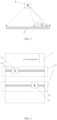
- an existing mineral separation system includes a ray source 1, a detector 2, a conveyor belt, a blowing device, and a control device.
- a principle lies in that: the ray source 1 generates X-rays and irradiates an ore block to be separated on the conveyor belt, transmitted rays are received by the detector 2 for imaging; as different mineral components in the ore block have different attenuation coefficients for the rays, an image of the ore block obtained under the irradiation of the ray source 1 of the same power has a distribution of different optical densities corresponding to different components in the ore block, then the control device analyzes and position the mineral components accordingly, and determines, according to a predetermined threshold, an ore block that needs to be separated, which is then blown and separated by the blowing device.
- a region ab is an operating region of the conveyor belt.
- the ore block to be separated is placed in the region ab. If two ore blocks (such as ore block I and ore block II) are arranged adjacent to each other on the conveyor belt, the ore block I and the ore block II may block each other since there is only one ray source 1.
- a projection region on the detector is a region cd, and the detector 2 may receive a superposition information of the ore block I and the ore block II.
- Embodiments of the present disclosure provide a mineral separation system, including a conveyor belt and at least two imaging devices, where each of the at least two imaging devices includes a ray source located above the conveyor belt and a ray detector located below the conveyor belt, the ray source and the ray detector of each imaging device are arranged facing each other in a direction perpendicular to the conveyor belt, the ray sources are staggered in a length direction of the conveyor belt and a width direction of the conveyor belt, projection regions of ray beams emitted by the ray sources do not overlap with each other, and orthographic projections of the ray beams emitted by the ray sources have an overlapping portion in the length direction of the conveyor belt.
- the conveyor belt has an operating region for placing a mineral to be separated, and an orthographic projection of the operating region in the length direction of the conveying belt falls within the overlapping portion.
- the ray source is arranged obliquely with respect to a conveying plane of the conveyor belt.
- the mineral separation system includes two imaging devices; and the ray sources of the two imaging device are respectively located on both sides of a symmetry plane in the length direction of the conveyor belt.
- the ray sources of the two imaging devices have a same distance to the symmetry plane.
- the ray sources of the imaging devices are arranged at equal intervals in the length direction and/or the width direction of the conveyor belt.
- the imaging device further includes a collimator configured to collimate a ray beam emitted by the ray source.
- the mineral separation system further includes a frame, and the ray source is rotatably connected to the frame.
- the mineral separation system further includes a blowing device and a control device, and the control device is electrically connected to the ray source, the ray detector, the conveyor belt and the blowing device.
- the blowing device includes a high-pressure nozzle, and the high-pressure nozzle includes blowing holes arranged in an array.
- the mineral separation system includes at least two imaging devices. Orthographic projections of ray beams of the imaging devices have an overlapping portion in the length direction of the conveyor belt. A region of the conveyor belt that faces the overlapping region in the width direction is used as an operating region for conveying an ore block to be separated. Each imaging device may image the ore block placed in the operating region. By imaging the same ore block from different angles using different imaging devices, it is possible to improve an accuracy of composition analysis of the ore block and improve a positioning accuracy of the ore block.
- a mineral separation system including a conveyor belt 21 and at least two imaging devices 22.
- Each imaging device 22 includes a ray source 221 located above the conveyor belt 21 and a ray detector 222 located below the conveyor belt 21.
- the ray source 221 and the ray detector 222 of each imaging device 22 are arranged facing each other in a direction perpendicular to the conveyor belt 21.
- the ray sources 221 are arranged in a stagger manner in a length direction and a width direction of the conveyor belt 21. Projection regions of ray beams of the ray sources 221 do not overlap with each other. Orthographic projections of the ray beams emitted by the ray sources 221 have an overlapping portion in the length direction of the conveyor belt 21.
- the mineral separation system includes at least two imaging devices, the orthographic projections of the ray beams emitted by the ray sources of the imaging devices have an overlapping portion in the length direction of the conveyor belt, and the conveyor belt conveys an ore block to be separated in the length direction (i.e., a conveying direction).
- an ore block may be imaged at least twice to form at least two images.
- the imaging devices may scan and image the ore block on the conveyor belt from different angles, so that an accuracy of composition analysis and a positioning precision of the ore block may be improved.
- the conveyor belt has an operating region for placing the ore block to be separated, and an orthographic projection of the operating region in the length direction of the conveying belt falls within the above-mentioned overlapping portion.
- the orthographic projection of the operating region in the length direction of the conveyor belt may completely coincide with a bottom of the overlapping portion, or the orthographic projection of the operating region in the length direction of the conveyor belt is a part of the bottom of the above-mentioned overlapping portion.
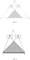
- a shaded region illustrates the overlapping portion of the orthographic projections of the ray beams emitted by the two ray sources 221 in the length direction of the conveyor belt 21.
- the operating region of the conveyor belt 21 for placing the ore block to be separated faces a region AB. Generally, the ore block to be separated in the operating region does not exceed a range of the region AB.
- the ray sources 221 are staggered in the length direction and the width direction of the conveyor belt 21, so that the imaging devices may scan and image the ore block on the conveyor belt 21 from different angles, and the problem of errors in composition analysis and positioning when imaging the ore block using a single ray source from a single angle may be overcome.
- the projection regions of the ray beams emitted by the ray sources 221 do not overlap with each other, it may be ensured that the imaging of the imaging devices do not interfere with each other and the imaging regions do not overlap with each other.
- the plurality of imaging devices may scan a same ore block to obtain a plurality of scanning images.
- a comprehensive analysis may be performed on the plurality of scanning images to obtain an average value of the composition of the ore block, thereby improving the accuracy of composition analysis.
- the plurality of scanning images may also be used for a comprehensive analysis of positions of ore blocks, which may help to improve a positioning precision of the ore block and an accuracy of positioning blowing, thereby ensuring that the separated ore block meets a separation requirement.
- the mineral separation system has a frame (not shown), which may be used to support the conveyor belt 21, the ray source 221 and the ray detector 222.
- the mineral separation system further includes a blowing device and a control device.
- the blowing device is installed on the frame, and the control device is electrically connected to the conveyor belt, the ray source, the ray detector and the blowing device.
- an orthographic projection of any ray source 221 on a conveying plane of the conveyor belt 21 falls within the conveyor belt 21.
- a distance between the orthographic projection of any ray source on the conveying plane of the conveyor belt 21 and a conveying end of the conveyor belt 21 is not less than a predetermined spacing.
- a blowing device is installed on the frame.
- the blowing device includes a high-pressure nozzle, and the high-pressure nozzle includes a plurality of blowing holes arranged in an array.
- the high-pressure nozzle is provided above the conveyor belt 21 and is used to blow a target ore block on the conveyor belt 21.
- the blowing device is movably installed on the frame, so that a blowing position may be adjusted based on a control command of the control device.
- the ray sources are located at inner sides of the conveyor belt 21, so that most of the ray beams emitted by the ray source 221 distributed near an edge of the conveyor belt 21 may irradiate the operating region of the conveyor belt 21.
- such design may allow the aforementioned overlapping portion to substantially face a middle region in the width direction of the conveyor belt 21, that is, it may be ensured that the operating region is substantially located in the middle region in the width direction of the conveyor belt 21.
- a distance between the ray source 221 of each imaging device 22 and the conveying end of the conveyor belt 21 is not less than a predetermined spacing.
- the associated control device may analyze the mineral composition according to the image for the ore block, determine a moving speed of the conveyor belt 21 according to an imaging time difference between different imaging devices and the spacing between different imaging devices, and control the corresponding blowing device to blow air before the ore block reaches the conveying end of the conveyor belt 21. If the ray source 221 is located at the conveying end of the conveyor belt 21, it is possible that the composition analysis, the positioning and the separation of the ore block have not been completed when the ore block leaves the conveyor belt 21.
- blowing device located at the conveying end of the conveyor belt 21 .
- an intermediate blowing device a blowing device between the plurality of imaging devices 22.
- an imaging device located before the intermediate blowing device After the primary blowing, it is possible to perform a composition analysis and positioning again by using an imaging device located after the intermediate blowing device, and perform a secondary blowing of ore blocks according to a corresponding scanning result and requirement, so that the accuracy of mineral separation may be further improved.
- the ray source 221 may be arranged obliquely with respect to the conveying plane of the conveyor belt 21, so that a size of the overlapping portion of the ray beams emitted by the ray sources 221 in the imaging devices 22 may be adjusted.
- the mineral separation system includes two imaging devices 22, and the ray sources 221 of the two imaging devices 22 are respectively located on both sides of a symmetry plane in the length direction of the conveyor belt 21.
- Such design may allow the aforementioned overlapping portion to substantially face the middle region in the width direction of the conveyor belt 21, so as to ensure that the operating region is substantially located in the middle region in the width direction of the conveyor belt 21, prevent the operating region from being biased to one side of the conveyor belt, and ensure that the conveyor belt 21 may convey the ore block smoothly.
- the ray sources of the two imaging devices 22 have a same distance to the symmetry plane, so that the operating region is located in the middle region in the width direction of the conveyor belt 21.
- a shaded region represents the overlapping portion of the orthographic projections of the ray beams of the two ray sources 221 in the length direction of the conveyor belt 21.
- An ore block located in the shaded region of the conveyor belt may be successively detected by the two imaging devices, an ore block located in a region CA of the conveyor belt may only be detected by a left imaging device 221, and an ore block located in a region BD of the conveyor belt may only be detected by a right imaging device 221. Therefore, the region AB is preferably used as the operating region of the conveyor belt for placing the ore block to be separated.
- the mineral separation system includes at least two imaging devices 22, and the ray sources 221 of the imaging devices 22 are arranged at equal intervals in the width direction of the conveyor belt 21.
- Such design may allow the aforementioned overlapping portion to substantially face the middle region in the width direction of the conveyor belt 21, so as to ensure that the operating region is substantially located in the middle region in the width direction of the conveyor belt 21, prevent the operating region from being biased to one side of the conveyor belt, and ensure that the conveyor belt may convey the mineral block smoothly.
- the ray sources 221 of the imaging devices 22 are arranged at equal intervals in the length direction of the conveyor belt 21.
- FIG. 4 shows a schematic diagram of a projection structure in a length direction of a mineral separation system provided by another embodiment of the present disclosure.
- each imaging device 22 further includes a collimator (not shown).
- the collimator faces the ray source in a direction perpendicular to the conveying belt 21.
- the collimator is arranged between the ray source 221 and the conveyor belt 21 to collimate a ray beam emitted by the ray source 221.
- a right field angle of a right ray source 221 may be reduced using a collimator, and a left field angle of a left ray source 221 may be reduced using a collimator, so that the field angles of the two ray sources 221 may be limited within the region AB covering the conveyor belt.
- the imaging device using the collimator is suitable for a conveyor belt with a narrow width, and the region AB as the operating region may cover an entire conveying surface of the conveyor belt.
- FIG. 5 shows a schematic diagram of a projection structure in a length direction of a mineral separation system according to another embodiment of the present disclosure.
- the mineral separation system provided by such embodiment differs from the mineral separation system in the embodiment of FIG. 3 in that the ray source is rotatably connected to the frame.
- a ray source bracket is provided on the frame, and the ray source is hinged to the ray source bracket.
- the ray source is locked to the ray source bracket through a locking member (such as screws/bolts).
- the ray sources are suitable for a conveyor belt with a narrow width, and the region AB as the operating region may cover the entire conveying surface of the conveyor belt.
- FIG. 6 shows a schematic structural diagram of a mineral separation system provided by an embodiment of the present disclosure for irradiating and imaging adjacent ore blocks.
- the mineral separation system shown in FIG. 4 is used in such embodiments.
- the mineral separation system includes two imaging devices, each imaging device includes a collimator, and the entire conveying surface of the conveyor belt is the operating region AB.
- the ore block II is partially or completely blocked by the ore block I in the projection direction of the ray beam, so that a ray information received by the corresponding ray detector is a superposition information of the ore block I and the ore block II; when the right ray source 221 is used, the ray information received by the corresponding ray detector includes the information about rays passing through the ore block I and the information about rays passing through the ore block II, so that the ore block I and the ore block II may be distinguished.
- a projection region of the ore block I on the ray detector of the right imaging device is EF
- a projection region of the ore block II on the ray detector of the right imaging device is GH.
- the use of two imaging devices may analyze the composition of adjacent arranged ore block I and ore block II more accurately, and the accuracy of composition analysis may be improved.
- the mineral separation system shown in FIG. 3 or FIG. 5 may accurately identify the composition of ore block and improve the accuracy of composition analysis; and may accurately identity the position of ore block and improve the positioning blowing precision.
- the ray source is an X-ray emitter.
- the ray source is used to emit a fan-shaped ray beam, and a field angle of the fan-shaped ray beam may be reduced by a collimator, so that a projection region of the fan-shaped ray beam may be reduced; or the ray source is used to emit a cone ray beam, which may be converted into a fan-shaped ray beam through a collimator.
- first first
- second second
- first information may also be referred to as a second information
- first information may also be referred to as a first information
Landscapes
- Health & Medical Sciences (AREA)
- General Health & Medical Sciences (AREA)
- Life Sciences & Earth Sciences (AREA)
- Chemical & Material Sciences (AREA)
- General Physics & Mathematics (AREA)
- Analytical Chemistry (AREA)
- Biochemistry (AREA)
- Physics & Mathematics (AREA)
- Immunology (AREA)
- Pathology (AREA)
- Toxicology (AREA)
- Engineering & Computer Science (AREA)
- Environmental & Geological Engineering (AREA)
- General Life Sciences & Earth Sciences (AREA)
- Geology (AREA)
- Remote Sensing (AREA)
- Food Science & Technology (AREA)
- Medicinal Chemistry (AREA)
- Analysing Materials By The Use Of Radiation (AREA)
Abstract
Description
- The present disclosure generally relates to a field of mineral separation technology, and more specifically to a mineral separation system.
- In recent years, with a rapid development of economy, a contradiction between supply and demand of mineral resources has become increasingly prominent, and high-grade, easy-to-select, and easy-to-smelt mineral resources have been increasingly reduced. In order to improve a comprehensive utilization of mineral resources, save resources, and ensure a provision of high-quality mineral products, it has become an urgent need to effectively utilize mineral resources such as associated minerals, fine-grained minerals and low-grade minerals and improve a separation efficiency of such mineral products.
- At present, X-ray transmission imaging technology (XRT) is used for separation of mineral products. Referring to
FIG. 1 , an existing mineral separation system includes aray source 1, adetector 2, a conveyor belt, a blowing device, and a control device. A principle lies in that: theray source 1 generates X-rays and irradiates an ore block to be separated on the conveyor belt, transmitted rays are received by thedetector 2 for imaging; as different mineral components in the ore block have different attenuation coefficients for the rays, an image of the ore block obtained under the irradiation of theray source 1 of the same power has a distribution of different optical densities corresponding to different components in the ore block, then the control device analyzes and position the mineral components accordingly, and determines, according to a predetermined threshold, an ore block that needs to be separated, which is then blown and separated by the blowing device. - Referring to
FIG. 1 , a region ab is an operating region of the conveyor belt. The ore block to be separated is placed in the region ab. If two ore blocks (such as ore block I and ore block II) are arranged adjacent to each other on the conveyor belt, the ore block I and the ore block II may block each other since there is only oneray source 1. When X-rays irradiate the ore block I and the ore block II, a projection region on the detector is a region cd, and thedetector 2 may receive a superposition information of the ore block I and the ore block II. It may fail to obtain the information of the ore block I and the information of the ore block II separately, and fail to accurately analyze the two ore blocks separately, which affects an accuracy of a composition analysis. Further, it may fail to accurately determine a position of each ore block in a width direction of the conveyor belt, which affects an accuracy of positioning blowing. - In view of the above defects or deficiencies in the related art, it is desired to provide a mineral separation system.
- Embodiments of the present disclosure provide a mineral separation system, including a conveyor belt and at least two imaging devices, where each of the at least two imaging devices includes a ray source located above the conveyor belt and a ray detector located below the conveyor belt, the ray source and the ray detector of each imaging device are arranged facing each other in a direction perpendicular to the conveyor belt, the ray sources are staggered in a length direction of the conveyor belt and a width direction of the conveyor belt, projection regions of ray beams emitted by the ray sources do not overlap with each other, and orthographic projections of the ray beams emitted by the ray sources have an overlapping portion in the length direction of the conveyor belt.
- Further, the conveyor belt has an operating region for placing a mineral to be separated, and an orthographic projection of the operating region in the length direction of the conveying belt falls within the overlapping portion.
- Further, the ray source is arranged obliquely with respect to a conveying plane of the conveyor belt.
- Further, the mineral separation system includes two imaging devices; and the ray sources of the two imaging device are respectively located on both sides of a symmetry plane in the length direction of the conveyor belt.
- Further, the ray sources of the two imaging devices have a same distance to the symmetry plane.
- Further, the ray sources of the imaging devices are arranged at equal intervals in the length direction and/or the width direction of the conveyor belt.
- Further, the imaging device further includes a collimator configured to collimate a ray beam emitted by the ray source.
- Further, the mineral separation system further includes a frame, and the ray source is rotatably connected to the frame.
- Further, the mineral separation system further includes a blowing device and a control device, and the control device is electrically connected to the ray source, the ray detector, the conveyor belt and the blowing device.
- Further, the blowing device includes a high-pressure nozzle, and the high-pressure nozzle includes blowing holes arranged in an array.
- Technical solutions provided by embodiments of the present disclosure have the following beneficial effects.
- The mineral separation system provided by embodiments of the present disclosure includes at least two imaging devices. Orthographic projections of ray beams of the imaging devices have an overlapping portion in the length direction of the conveyor belt. A region of the conveyor belt that faces the overlapping region in the width direction is used as an operating region for conveying an ore block to be separated. Each imaging device may image the ore block placed in the operating region. By imaging the same ore block from different angles using different imaging devices, it is possible to improve an accuracy of composition analysis of the ore block and improve a positioning accuracy of the ore block.
- Other features, objectives and advantages of the present disclosure will become clearer upon reading the detailed description of non-limiting embodiments with reference to the accompanying drawings. In the accompanying drawings:
-
FIG. 1 shows a schematic structural diagram of a mineral separation system in the related art; -
FIG. 2 shows a schematic structural diagram of a mineral separation system provided by an embodiment of the present disclosure; -
FIG. 3 shows a schematic diagram of a projection structure in a length direction of a mineral separation system provided by an embodiment of the present disclosure; -
FIG. 4 shows a schematic diagram of a projection structure in a length direction of a mineral separation system provided by another embodiment of the present disclosure; -
FIG. 5 shows a schematic diagram of a projection structure in a length direction of a mineral separation system provided by still another embodiment of the present disclosure; and -
FIG. 6 shows a schematic structural diagram of a mineral separation system provided by an embodiment of the present disclosure for irradiating and imaging adjacent ore blocks. - The present disclosure will be further described in detail below in conjunction with the accompanying drawings and embodiments. It may be understood that the specific embodiments described here are just used to explain the relevant invention, but not to limit the invention. It should also be noted that, for sake of description, only the parts related to the invention are shown in the accompanying drawings.
- It should be noted that, as long as there is no conflict, embodiments and features in embodiments of the present disclosure may be combined with each other. The present disclosure will be described in detail below with reference to the accompanying drawings and embodiments.
- As shown in
FIG. 2 andFIG. 3 , embodiments of the present disclosure provide a mineral separation system, including a conveyor belt 21 and at least two imaging devices 22. Each imaging device 22 includes aray source 221 located above the conveyor belt 21 and a ray detector 222 located below the conveyor belt 21. Theray source 221 and the ray detector 222 of each imaging device 22 are arranged facing each other in a direction perpendicular to the conveyor belt 21. Theray sources 221 are arranged in a stagger manner in a length direction and a width direction of the conveyor belt 21. Projection regions of ray beams of theray sources 221 do not overlap with each other. Orthographic projections of the ray beams emitted by theray sources 221 have an overlapping portion in the length direction of the conveyor belt 21. - In such embodiments, the mineral separation system includes at least two imaging devices, the orthographic projections of the ray beams emitted by the ray sources of the imaging devices have an overlapping portion in the length direction of the conveyor belt, and the conveyor belt conveys an ore block to be separated in the length direction (i.e., a conveying direction). Thus, an ore block may be imaged at least twice to form at least two images. In the width direction of the conveyor belt, the imaging devices may scan and image the ore block on the conveyor belt from different angles, so that an accuracy of composition analysis and a positioning precision of the ore block may be improved.
- Specifically, the conveyor belt has an operating region for placing the ore block to be separated, and an orthographic projection of the operating region in the length direction of the conveying belt falls within the above-mentioned overlapping portion.
- For example, the orthographic projection of the operating region in the length direction of the conveyor belt may completely coincide with a bottom of the overlapping portion, or the orthographic projection of the operating region in the length direction of the conveyor belt is a part of the bottom of the above-mentioned overlapping portion.
- Referring to
FIG. 3 , a shaded region illustrates the overlapping portion of the orthographic projections of the ray beams emitted by the tworay sources 221 in the length direction of the conveyor belt 21. The operating region of the conveyor belt 21 for placing the ore block to be separated faces a region AB. Generally, the ore block to be separated in the operating region does not exceed a range of the region AB. - In such embodiments, the
ray sources 221 are staggered in the length direction and the width direction of the conveyor belt 21, so that the imaging devices may scan and image the ore block on the conveyor belt 21 from different angles, and the problem of errors in composition analysis and positioning when imaging the ore block using a single ray source from a single angle may be overcome. - Specifically, as the projection regions of the ray beams emitted by the
ray sources 221 do not overlap with each other, it may be ensured that the imaging of the imaging devices do not interfere with each other and the imaging regions do not overlap with each other. - In addition, the plurality of imaging devices may scan a same ore block to obtain a plurality of scanning images. A comprehensive analysis may be performed on the plurality of scanning images to obtain an average value of the composition of the ore block, thereby improving the accuracy of composition analysis. The plurality of scanning images may also be used for a comprehensive analysis of positions of ore blocks, which may help to improve a positioning precision of the ore block and an accuracy of positioning blowing, thereby ensuring that the separated ore block meets a separation requirement.
- Further, the mineral separation system has a frame (not shown), which may be used to support the conveyor belt 21, the
ray source 221 and the ray detector 222. - The mineral separation system further includes a blowing device and a control device. The blowing device is installed on the frame, and the control device is electrically connected to the conveyor belt, the ray source, the ray detector and the blowing device.
- Specifically, an orthographic projection of any
ray source 221 on a conveying plane of the conveyor belt 21 falls within the conveyor belt 21. - A distance between the orthographic projection of any ray source on the conveying plane of the conveyor belt 21 and a conveying end of the conveyor belt 21 is not less than a predetermined spacing.
- At the conveying end of the conveyor belt 21, a blowing device is installed on the frame. The blowing device includes a high-pressure nozzle, and the high-pressure nozzle includes a plurality of blowing holes arranged in an array. The high-pressure nozzle is provided above the conveyor belt 21 and is used to blow a target ore block on the conveyor belt 21. Preferably, the blowing device is movably installed on the frame, so that a blowing position may be adjusted based on a control command of the control device.
- In both the width direction and the length direction of the conveyor belt 21, the ray sources are located at inner sides of the conveyor belt 21, so that most of the ray beams emitted by the
ray source 221 distributed near an edge of the conveyor belt 21 may irradiate the operating region of the conveyor belt 21. In the width direction of the conveyor belt 21, such design may allow the aforementioned overlapping portion to substantially face a middle region in the width direction of the conveyor belt 21, that is, it may be ensured that the operating region is substantially located in the middle region in the width direction of the conveyor belt 21. - In the length direction of the conveyor belt 21, a distance between the
ray source 221 of each imaging device 22 and the conveying end of the conveyor belt 21 is not less than a predetermined spacing. After the imaging device 22 detects an ore block and generates an image for the ore block, the associated control device may analyze the mineral composition according to the image for the ore block, determine a moving speed of the conveyor belt 21 according to an imaging time difference between different imaging devices and the spacing between different imaging devices, and control the corresponding blowing device to blow air before the ore block reaches the conveying end of the conveyor belt 21. If theray source 221 is located at the conveying end of the conveyor belt 21, it is possible that the composition analysis, the positioning and the separation of the ore block have not been completed when the ore block leaves the conveyor belt 21. - In the aforementioned embodiments, an example in which the blowing device is located at the conveying end of the conveyor belt 21 is shown. However, according to actual needs, it is also possible to provide a blowing device (hereinafter referred to as an intermediate blowing device) between the plurality of imaging devices 22. In this way, it is possible to perform a primary blowing of ore blocks according to a scanning result and requirement of an imaging device located before the intermediate blowing device. After the primary blowing, it is possible to perform a composition analysis and positioning again by using an imaging device located after the intermediate blowing device, and perform a secondary blowing of ore blocks according to a corresponding scanning result and requirement, so that the accuracy of mineral separation may be further improved.
- Furthermore, the
ray source 221 may be arranged obliquely with respect to the conveying plane of the conveyor belt 21, so that a size of the overlapping portion of the ray beams emitted by theray sources 221 in the imaging devices 22 may be adjusted. - As an optional embodiment, the mineral separation system includes two imaging devices 22, and the
ray sources 221 of the two imaging devices 22 are respectively located on both sides of a symmetry plane in the length direction of the conveyor belt 21. Such design may allow the aforementioned overlapping portion to substantially face the middle region in the width direction of the conveyor belt 21, so as to ensure that the operating region is substantially located in the middle region in the width direction of the conveyor belt 21, prevent the operating region from being biased to one side of the conveyor belt, and ensure that the conveyor belt 21 may convey the ore block smoothly. - Specifically, it is preferable that the ray sources of the two imaging devices 22 have a same distance to the symmetry plane, so that the operating region is located in the middle region in the width direction of the conveyor belt 21.
- Referring to
FIG. 3 , a shaded region represents the overlapping portion of the orthographic projections of the ray beams of the tworay sources 221 in the length direction of the conveyor belt 21. An ore block located in the shaded region of the conveyor belt may be successively detected by the two imaging devices, an ore block located in a region CA of the conveyor belt may only be detected by aleft imaging device 221, and an ore block located in a region BD of the conveyor belt may only be detected by aright imaging device 221. Therefore, the region AB is preferably used as the operating region of the conveyor belt for placing the ore block to be separated. - Furthermore, the mineral separation system includes at least two imaging devices 22, and the
ray sources 221 of the imaging devices 22 are arranged at equal intervals in the width direction of the conveyor belt 21. Such design may allow the aforementioned overlapping portion to substantially face the middle region in the width direction of the conveyor belt 21, so as to ensure that the operating region is substantially located in the middle region in the width direction of the conveyor belt 21, prevent the operating region from being biased to one side of the conveyor belt, and ensure that the conveyor belt may convey the mineral block smoothly. - Furthermore, the
ray sources 221 of the imaging devices 22 are arranged at equal intervals in the length direction of the conveyor belt 21. -
FIG. 4 shows a schematic diagram of a projection structure in a length direction of a mineral separation system provided by another embodiment of the present disclosure. - Referring to
FIG. 4 , the mineral separation system provided by such embodiment differs from the mineral separation system in the embodiment ofFIG. 3 in that each imaging device 22 further includes a collimator (not shown). The collimator faces the ray source in a direction perpendicular to the conveying belt 21. The collimator is arranged between theray source 221 and the conveyor belt 21 to collimate a ray beam emitted by theray source 221. - As shown in
FIG. 4 , a right field angle of aright ray source 221 may be reduced using a collimator, and a left field angle of aleft ray source 221 may be reduced using a collimator, so that the field angles of the tworay sources 221 may be limited within the region AB covering the conveyor belt. - The imaging device using the collimator is suitable for a conveyor belt with a narrow width, and the region AB as the operating region may cover an entire conveying surface of the conveyor belt.
-
FIG. 5 shows a schematic diagram of a projection structure in a length direction of a mineral separation system according to another embodiment of the present disclosure. - Referring to
FIG. 5 , the mineral separation system provided by such embodiment differs from the mineral separation system in the embodiment ofFIG. 3 in that the ray source is rotatably connected to the frame. - For example, a ray source bracket is provided on the frame, and the ray source is hinged to the ray source bracket. The ray source is locked to the ray source bracket through a locking member (such as screws/bolts).
- As shown in
FIG. 5 , by rotating both ray sources at a certain angle, it is possible to limit the ray beams of the two ray sources within the region AB covering both ends of the conveyor belt. - Similarly, by adjusting the angle of the ray sources, the ray sources are suitable for a conveyor belt with a narrow width, and the region AB as the operating region may cover the entire conveying surface of the conveyor belt.
-
FIG. 6 shows a schematic structural diagram of a mineral separation system provided by an embodiment of the present disclosure for irradiating and imaging adjacent ore blocks. - The mineral separation system shown in
FIG. 4 is used in such embodiments. The mineral separation system includes two imaging devices, each imaging device includes a collimator, and the entire conveying surface of the conveyor belt is the operating region AB. - As shown in
FIG. 6 , in the operating region AB, for adjacent arranged ore block I and ore block II, when theleft ray source 221 is used, the ore block II is partially or completely blocked by the ore block I in the projection direction of the ray beam, so that a ray information received by the corresponding ray detector is a superposition information of the ore block I and the ore block II; when theright ray source 221 is used, the ray information received by the corresponding ray detector includes the information about rays passing through the ore block I and the information about rays passing through the ore block II, so that the ore block I and the ore block II may be distinguished. In this case, a projection region of the ore block I on the ray detector of the right imaging device is EF, and a projection region of the ore block II on the ray detector of the right imaging device is GH. Compared with the use of a single ray source, the use of two imaging devices may analyze the composition of adjacent arranged ore block I and ore block II more accurately, and the accuracy of composition analysis may be improved. Furthermore, based on two imaging devices, it is possible to more accurately obtain a longitudinal vertical projection of the ore block in the length direction of the conveyor belt and a transverse vertical projection perpendicular to the length direction of the conveyor belt, thereby accurately identifying the position of the ore block and improving a positioning blowing precision. - If the mineral separation system shown in
FIG. 3 orFIG. 5 is used in such embodiments, it is also possible to clearly distinguish the adjacent arranged ore block I and ore block II. The mineral separation system provided by any of the above-mentioned embodiments may accurately identify the composition of ore block and improve the accuracy of composition analysis; and may accurately identity the position of ore block and improve the positioning blowing precision. - In embodiments of the present disclosure, it is preferred that the ray source is an X-ray emitter. The ray source is used to emit a fan-shaped ray beam, and a field angle of the fan-shaped ray beam may be reduced by a collimator, so that a projection region of the fan-shaped ray beam may be reduced; or the ray source is used to emit a cone ray beam, which may be converted into a fan-shaped ray beam through a collimator.
- In the present disclosure, "first", "second", etc. are used to describe various information. However, the information should not be limited to those terms. Those terms are just used to distinguish information of the same type from each other. For example, without departing from the scope of the present disclosure, a first information may also be referred to as a second information, and similarly, a second information may also be referred to as a first information.
- In the description of the present disclosure, it should be understood that terms "center", "longitudinal", "transverse", "length", "width", "thickness", "upper", "lower", "before", "after", "left", "right", "vertical", "horizontal", "top", "bottom", "inside", "outside", "clockwise", "counterclockwise", "axial direction", "radial direction", "circumferential direction", etc. are used to indicate orientations or positional relationships shown based on the accompanying drawings, which are intended to facilitate the description of the present disclosure and simplify the description, not to indicate or imply that the device or element referred to must have a specific orientation or must be constructed or operated in a specific orientation, and should not be understood as limitations to the present disclosure.
- The above description is just an illustration of preferred embodiments of the present disclosure and technical principles used in the present disclosure. Those skilled in the art should understand that the scope of the invention involved in the present disclosure is not limited to technical solutions formed by a specific combination of the above technical features, but should also cover additional technical solutions formed by any combination of the above technical features or equivalent features without departing from the inventive concept, such as technical solutions formed by exchanging the above features with technical features disclosed in (but not limited to) the present disclosure with similar functions.
Claims (10)
- A mineral separation system, comprising:a conveyor belt; andat least two imaging devices,wherein each of the at least two imaging devices comprises a ray source located above the conveyor belt and a ray detector located below the conveyor belt, the ray source and the ray detector of each imaging device are arranged facing each other in a direction perpendicular to the conveyor belt, the ray sources are staggered in a length direction of the conveyor belt and a width direction of the conveyor belt, projection regions of ray beams emitted by the ray sources do not overlap with each other, and orthographic projections of the ray beams emitted by the ray sources have an overlapping portion in the length direction of the conveyor belt.
- The mineral separation system according to claim 1, wherein the conveyor belt has an operating region for placing a mineral to be separated, and an orthographic projection of the operating region in the length direction of the conveying belt falls within the overlapping portion.
- The mineral separation system according to claim 2, wherein the ray source is arranged obliquely with respect to a conveying plane of the conveyor belt.
- The mineral separation system according to any one of claims 1 to 3, wherein the mineral separation system comprises two imaging devices; and
the ray sources of the two imaging device are respectively located on both sides of a symmetry plane in the length direction of the conveyor belt. - The mineral separation system according to claim 4, wherein the ray sources of the two imaging devices have a same distance to the symmetry plane.
- The mineral separation system according to any one of claims 1 to 3, wherein the ray sources of the imaging devices are arranged at equal intervals in the length direction and/or the width direction of the conveyor belt.
- The mineral separation system according to any one of claims 1 to 3 and 5, wherein the imaging device further comprises a collimator configured to collimate a ray beam emitted by the ray source.
- The mineral separation system according to any one of claims 1 to 3 and 5, further comprising a frame, wherein the ray source is rotatably connected to the frame.
- The mineral separation system according to claim 1, further comprising a blowing device and a control device, wherein the control device is electrically connected to the ray source, the ray detector, the conveyor belt and the blowing device.
- The mineral separation system according to claim 9, wherein the blowing device comprises a high-pressure nozzle, and the high-pressure nozzle comprises blowing holes arranged in an array.
Applications Claiming Priority (2)
| Application Number | Priority Date | Filing Date | Title |
|---|---|---|---|
| CN202111613455.7A CN114146942A (en) | 2021-12-27 | 2021-12-27 | Mineral sorting system |
| PCT/CN2022/125074 WO2023124389A1 (en) | 2021-12-27 | 2022-10-13 | Mineral sorting system |
Publications (2)
| Publication Number | Publication Date |
|---|---|
| EP4458481A1 true EP4458481A1 (en) | 2024-11-06 |
| EP4458481A4 EP4458481A4 (en) | 2025-12-31 |
Family
ID=80452061
Family Applications (1)
| Application Number | Title | Priority Date | Filing Date |
|---|---|---|---|
| EP22913653.6A Pending EP4458481A4 (en) | 2021-12-27 | 2022-10-13 | MINERAL SORTING SYSTEM |
Country Status (4)
| Country | Link |
|---|---|
| EP (1) | EP4458481A4 (en) |
| CN (1) | CN114146942A (en) |
| MX (1) | MX2024007440A (en) |
| WO (1) | WO2023124389A1 (en) |
Families Citing this family (3)
| Publication number | Priority date | Publication date | Assignee | Title |
|---|---|---|---|---|
| CN114146942A (en) * | 2021-12-27 | 2022-03-08 | 同方威视技术股份有限公司 | Mineral sorting system |
| CN116871177B (en) * | 2023-09-05 | 2023-11-17 | 国擎(山东)信息科技有限公司 | Method and system for separating kaolin crude ore based on multispectral technology |
| CN222318720U (en) * | 2024-06-18 | 2025-01-07 | 常州锐奇精密测量技术有限公司 | Surface density full detection mechanism |
Family Cites Families (20)
| Publication number | Priority date | Publication date | Assignee | Title |
|---|---|---|---|---|
| CN2229844Y (en) * | 1995-07-11 | 1996-06-26 | 华中理工大学 | Ore Ray Separator |
| US6088423A (en) * | 1998-06-05 | 2000-07-11 | Vivid Technologies, Inc. | Multiview x-ray based system for detecting contraband such as in baggage |
| DE10125531A1 (en) * | 2001-05-23 | 2002-11-28 | Heimann Systems Gmbh & Co | Object inspection system for detecting disallowed items in baggage has radiation sources for producing three or more beams, and is enclosed in housing of separate apparatus |
| DE102004001790A1 (en) * | 2004-01-12 | 2005-08-04 | Commodas Daten- Und Systemtechnik Nach Mass Gmbh | Device for separating bulk materials |
| CN100565336C (en) * | 2005-11-21 | 2009-12-02 | 清华大学 | Imaging system |
| US8137976B2 (en) * | 2006-07-12 | 2012-03-20 | Varian Medical Systems, Inc. | Dual angle radiation scanning of objects |
| CN101561405B (en) * | 2008-04-17 | 2011-07-06 | 清华大学 | Straight-line track scanning imaging system and method |
| US20110142201A1 (en) * | 2009-12-15 | 2011-06-16 | General Electric Company | Multi-view imaging system and method |
| CN102735700B (en) * | 2012-06-18 | 2014-08-06 | 天津三英精密仪器有限公司 | X-ray micro-imaging system |
| CN103226114B (en) * | 2013-04-02 | 2015-09-30 | 清华大学 | Various visual angles stereoscopic radiation imaging system and method |
| CN104459812A (en) * | 2014-12-17 | 2015-03-25 | 同方威视技术股份有限公司 | Trailer-type multi-view item inspection system and its application method |
| CN105784733A (en) * | 2015-01-26 | 2016-07-20 | 公安部第研究所 | Channel type double-view-angle X-ray safety inspection device |
| CN105268634A (en) * | 2015-04-16 | 2016-01-27 | 天津美腾科技有限公司 | Intelligent mineral dry separation system based on intelligent arrayed air nozzles |
| CN205020424U (en) * | 2015-09-25 | 2016-02-10 | 重庆科技学院 | Mineral sorting unit and mineral sorting facilities based on X ray image |
| CN106040617A (en) * | 2016-05-29 | 2016-10-26 | 内蒙古科技大学 | Radioactive ore sorting machine |
| CN107677693B (en) * | 2017-09-26 | 2020-06-09 | 同方威视技术股份有限公司 | Scanning imaging system and imaging method for article security inspection |
| CN109821766A (en) * | 2019-03-05 | 2019-05-31 | 天津美腾科技有限公司 | TDS intelligence dry-dressing machine dijection source discrimination and system |
| CN210690842U (en) * | 2019-04-29 | 2020-06-05 | 公安部第一研究所 | A dual-view intelligent X-ray security inspection equipment |
| CN216779483U (en) * | 2021-12-27 | 2022-06-21 | 同方威视技术股份有限公司 | Mineral sorting system |
| CN114146942A (en) * | 2021-12-27 | 2022-03-08 | 同方威视技术股份有限公司 | Mineral sorting system |
-
2021
- 2021-12-27 CN CN202111613455.7A patent/CN114146942A/en active Pending
-
2022
- 2022-10-13 MX MX2024007440A patent/MX2024007440A/en unknown
- 2022-10-13 WO PCT/CN2022/125074 patent/WO2023124389A1/en not_active Ceased
- 2022-10-13 EP EP22913653.6A patent/EP4458481A4/en active Pending
Also Published As
| Publication number | Publication date |
|---|---|
| EP4458481A4 (en) | 2025-12-31 |
| CN114146942A (en) | 2022-03-08 |
| WO2023124389A1 (en) | 2023-07-06 |
| MX2024007440A (en) | 2024-07-04 |
Similar Documents
| Publication | Publication Date | Title |
|---|---|---|
| WO2023124389A1 (en) | Mineral sorting system | |
| EP3412210B1 (en) | X-ray collimator and x-ray imaging apparatus using same | |
| JP5936718B2 (en) | Particle beam rotation irradiation apparatus and particle beam therapy apparatus | |
| US7819580B2 (en) | Arm frame structure and scan apparatus having the same | |
| EP2899537B1 (en) | Luggage ct safety inspection system and detector device thereof | |
| US10727026B2 (en) | Charged particle beam inspection method | |
| RU2253861C2 (en) | Method and device for detecting prohibited objects | |
| EP3182175B1 (en) | X-ray diffraction detection system and method | |
| US20180144842A1 (en) | Controlling accelerator system | |
| JP2008531377A (en) | Optical tracking system for refueling | |
| US20250035569A1 (en) | Security inspection device, security inspection system, and security inspection method | |
| US20240249401A1 (en) | Method for determining a position of a corner region of an electrode assembly stack | |
| WO2011097386A1 (en) | Multiple plane multi-inverse fan-beam detection systems and method for using the same | |
| JP2019211296A (en) | Electron beam inspection device and electron beam inspection method | |
| HK1218162A1 (en) | Safety inspection apparatus | |
| CN115825117B (en) | Digital ray detection device and detection method for fillet weld of finned tube of gasifier | |
| CN115508392A (en) | Scanning imaging apparatus and scanning imaging method | |
| WO2023056881A1 (en) | Ct imaging system | |
| KR102263464B1 (en) | X-ray inspection apparatus for welded steel pipe having transporting and position adjusting means | |
| CN113884513B (en) | Security check machine and cargo detection method | |
| CN218726798U (en) | scanning imaging equipment | |
| US6628753B2 (en) | X-ray imaging apparatus | |
| KR20240153261A (en) | Inspection apparatus and operation method thereof | |
| CN114121334B (en) | A ray collimation adjustment device | |
| JP2020068885A (en) | Positioning phantom for X-ray imaging system |
Legal Events
| Date | Code | Title | Description |
|---|---|---|---|
| STAA | Information on the status of an ep patent application or granted ep patent |
Free format text: STATUS: THE INTERNATIONAL PUBLICATION HAS BEEN MADE |
|
| PUAI | Public reference made under article 153(3) epc to a published international application that has entered the european phase |
Free format text: ORIGINAL CODE: 0009012 |
|
| STAA | Information on the status of an ep patent application or granted ep patent |
Free format text: STATUS: REQUEST FOR EXAMINATION WAS MADE |
|
| 17P | Request for examination filed |
Effective date: 20240514 |
|
| AK | Designated contracting states |
Kind code of ref document: A1 Designated state(s): AL AT BE BG CH CY CZ DE DK EE ES FI FR GB GR HR HU IE IS IT LI LT LU LV MC ME MK MT NL NO PL PT RO RS SE SI SK SM TR |
|
| DAV | Request for validation of the european patent (deleted) | ||
| DAX | Request for extension of the european patent (deleted) | ||
| A4 | Supplementary search report drawn up and despatched |
Effective date: 20251202 |
|
| RIC1 | Information provided on ipc code assigned before grant |
Ipc: B07C 5/02 20060101AFI20251126BHEP Ipc: B07C 5/34 20060101ALI20251126BHEP Ipc: B07C 5/36 20060101ALI20251126BHEP Ipc: G01N 23/04 20180101ALI20251126BHEP Ipc: G01N 23/083 20180101ALI20251126BHEP Ipc: G01N 23/12 20180101ALI20251126BHEP Ipc: G01N 33/24 20060101ALI20251126BHEP Ipc: B07C 5/342 20060101ALI20251126BHEP |