EP4458471A1 - Container and purification apparatus - Google Patents
Container and purification apparatus Download PDFInfo
- Publication number
- EP4458471A1 EP4458471A1 EP22915488.5A EP22915488A EP4458471A1 EP 4458471 A1 EP4458471 A1 EP 4458471A1 EP 22915488 A EP22915488 A EP 22915488A EP 4458471 A1 EP4458471 A1 EP 4458471A1
- Authority
- EP
- European Patent Office
- Prior art keywords
- container
- solution
- discharge
- discharge port
- introduction
- Prior art date
- Legal status (The legal status is an assumption and is not a legal conclusion. Google has not performed a legal analysis and makes no representation as to the accuracy of the status listed.)
- Pending
Links
Images




Classifications
-
- C—CHEMISTRY; METALLURGY
- C02—TREATMENT OF WATER, WASTE WATER, SEWAGE, OR SLUDGE
- C02F—TREATMENT OF WATER, WASTE WATER, SEWAGE, OR SLUDGE
- C02F1/00—Treatment of water, waste water, or sewage
- C02F1/72—Treatment of water, waste water, or sewage by oxidation
- C02F1/722—Oxidation by peroxides
-
- G—PHYSICS
- G01—MEASURING; TESTING
- G01N—INVESTIGATING OR ANALYSING MATERIALS BY DETERMINING THEIR CHEMICAL OR PHYSICAL PROPERTIES
- G01N1/00—Sampling; Preparing specimens for investigation
- G01N1/28—Preparing specimens for investigation including physical details of (bio-)chemical methods covered elsewhere, e.g. G01N33/50, C12Q
- G01N1/40—Concentrating samples
- G01N1/4077—Concentrating samples by other techniques involving separation of suspended solids
-
- B—PERFORMING OPERATIONS; TRANSPORTING
- B03—SEPARATION OF SOLID MATERIALS USING LIQUIDS OR USING PNEUMATIC TABLES OR JIGS; MAGNETIC OR ELECTROSTATIC SEPARATION OF SOLID MATERIALS FROM SOLID MATERIALS OR FLUIDS; SEPARATION BY HIGH-VOLTAGE ELECTRIC FIELDS
- B03B—SEPARATING SOLID MATERIALS USING LIQUIDS OR USING PNEUMATIC TABLES OR JIGS
- B03B5/00—Washing granular, powdered or lumpy materials; Wet separating
- B03B5/28—Washing granular, powdered or lumpy materials; Wet separating by sink-float separation
- B03B5/30—Washing granular, powdered or lumpy materials; Wet separating by sink-float separation using heavy liquids or suspensions
- B03B5/36—Devices therefor, other than using centrifugal force
-
- B—PERFORMING OPERATIONS; TRANSPORTING
- B29—WORKING OF PLASTICS; WORKING OF SUBSTANCES IN A PLASTIC STATE IN GENERAL
- B29B—PREPARATION OR PRETREATMENT OF THE MATERIAL TO BE SHAPED; MAKING GRANULES OR PREFORMS; RECOVERY OF PLASTICS OR OTHER CONSTITUENTS OF WASTE MATERIAL CONTAINING PLASTICS
- B29B17/00—Recovery of plastics or other constituents of waste material containing plastics
- B29B17/02—Separating plastics from other materials
-
- C—CHEMISTRY; METALLURGY
- C02—TREATMENT OF WATER, WASTE WATER, SEWAGE, OR SLUDGE
- C02F—TREATMENT OF WATER, WASTE WATER, SEWAGE, OR SLUDGE
- C02F1/00—Treatment of water, waste water, or sewage
- C02F1/68—Treatment of water, waste water, or sewage by addition of specified substances, e.g. trace elements, for ameliorating potable water
-
- G—PHYSICS
- G01—MEASURING; TESTING
- G01N—INVESTIGATING OR ANALYSING MATERIALS BY DETERMINING THEIR CHEMICAL OR PHYSICAL PROPERTIES
- G01N1/00—Sampling; Preparing specimens for investigation
- G01N1/28—Preparing specimens for investigation including physical details of (bio-)chemical methods covered elsewhere, e.g. G01N33/50, C12Q
- G01N1/34—Purifying; Cleaning
-
- G—PHYSICS
- G01—MEASURING; TESTING
- G01N—INVESTIGATING OR ANALYSING MATERIALS BY DETERMINING THEIR CHEMICAL OR PHYSICAL PROPERTIES
- G01N1/00—Sampling; Preparing specimens for investigation
- G01N1/28—Preparing specimens for investigation including physical details of (bio-)chemical methods covered elsewhere, e.g. G01N33/50, C12Q
- G01N1/40—Concentrating samples
- G01N1/4022—Concentrating samples by thermal techniques; Phase changes
-
- G—PHYSICS
- G01—MEASURING; TESTING
- G01N—INVESTIGATING OR ANALYSING MATERIALS BY DETERMINING THEIR CHEMICAL OR PHYSICAL PROPERTIES
- G01N1/00—Sampling; Preparing specimens for investigation
- G01N1/28—Preparing specimens for investigation including physical details of (bio-)chemical methods covered elsewhere, e.g. G01N33/50, C12Q
- G01N1/40—Concentrating samples
- G01N1/4044—Concentrating samples by chemical techniques; Digestion; Chemical decomposition
-
- B—PERFORMING OPERATIONS; TRANSPORTING
- B01—PHYSICAL OR CHEMICAL PROCESSES OR APPARATUS IN GENERAL
- B01D—SEPARATION
- B01D21/00—Separation of suspended solid particles from liquids by sedimentation
- B01D21/0084—Enhancing liquid-particle separation using the flotation principle
-
- B—PERFORMING OPERATIONS; TRANSPORTING
- B01—PHYSICAL OR CHEMICAL PROCESSES OR APPARATUS IN GENERAL
- B01D—SEPARATION
- B01D21/00—Separation of suspended solid particles from liquids by sedimentation
- B01D21/24—Feed or discharge mechanisms for settling tanks
- B01D21/2433—Discharge mechanisms for floating particles
-
- B—PERFORMING OPERATIONS; TRANSPORTING
- B03—SEPARATION OF SOLID MATERIALS USING LIQUIDS OR USING PNEUMATIC TABLES OR JIGS; MAGNETIC OR ELECTROSTATIC SEPARATION OF SOLID MATERIALS FROM SOLID MATERIALS OR FLUIDS; SEPARATION BY HIGH-VOLTAGE ELECTRIC FIELDS
- B03B—SEPARATING SOLID MATERIALS USING LIQUIDS OR USING PNEUMATIC TABLES OR JIGS
- B03B5/00—Washing granular, powdered or lumpy materials; Wet separating
- B03B5/28—Washing granular, powdered or lumpy materials; Wet separating by sink-float separation
- B03B5/30—Washing granular, powdered or lumpy materials; Wet separating by sink-float separation using heavy liquids or suspensions
-
- B—PERFORMING OPERATIONS; TRANSPORTING
- B03—SEPARATION OF SOLID MATERIALS USING LIQUIDS OR USING PNEUMATIC TABLES OR JIGS; MAGNETIC OR ELECTROSTATIC SEPARATION OF SOLID MATERIALS FROM SOLID MATERIALS OR FLUIDS; SEPARATION BY HIGH-VOLTAGE ELECTRIC FIELDS
- B03D—FLOTATION; DIFFERENTIAL SEDIMENTATION
- B03D1/00—Flotation
- B03D1/14—Flotation machines
-
- B—PERFORMING OPERATIONS; TRANSPORTING
- B29—WORKING OF PLASTICS; WORKING OF SUBSTANCES IN A PLASTIC STATE IN GENERAL
- B29B—PREPARATION OR PRETREATMENT OF THE MATERIAL TO BE SHAPED; MAKING GRANULES OR PREFORMS; RECOVERY OF PLASTICS OR OTHER CONSTITUENTS OF WASTE MATERIAL CONTAINING PLASTICS
- B29B17/00—Recovery of plastics or other constituents of waste material containing plastics
- B29B17/02—Separating plastics from other materials
- B29B2017/0213—Specific separating techniques
- B29B2017/0217—Mechanical separating techniques; devices therefor
- B29B2017/0224—Screens, sieves
-
- B—PERFORMING OPERATIONS; TRANSPORTING
- B29—WORKING OF PLASTICS; WORKING OF SUBSTANCES IN A PLASTIC STATE IN GENERAL
- B29B—PREPARATION OR PRETREATMENT OF THE MATERIAL TO BE SHAPED; MAKING GRANULES OR PREFORMS; RECOVERY OF PLASTICS OR OTHER CONSTITUENTS OF WASTE MATERIAL CONTAINING PLASTICS
- B29B17/00—Recovery of plastics or other constituents of waste material containing plastics
- B29B17/02—Separating plastics from other materials
- B29B2017/0213—Specific separating techniques
- B29B2017/0217—Mechanical separating techniques; devices therefor
- B29B2017/0237—Mechanical separating techniques; devices therefor using density difference
- B29B2017/0244—Mechanical separating techniques; devices therefor using density difference in liquids
-
- C—CHEMISTRY; METALLURGY
- C02—TREATMENT OF WATER, WASTE WATER, SEWAGE, OR SLUDGE
- C02F—TREATMENT OF WATER, WASTE WATER, SEWAGE, OR SLUDGE
- C02F1/00—Treatment of water, waste water, or sewage
- C02F2001/007—Processes including a sedimentation step
-
- C—CHEMISTRY; METALLURGY
- C02—TREATMENT OF WATER, WASTE WATER, SEWAGE, OR SLUDGE
- C02F—TREATMENT OF WATER, WASTE WATER, SEWAGE, OR SLUDGE
- C02F2101/00—Nature of the contaminant
- C02F2101/10—Inorganic compounds
-
- C—CHEMISTRY; METALLURGY
- C02—TREATMENT OF WATER, WASTE WATER, SEWAGE, OR SLUDGE
- C02F—TREATMENT OF WATER, WASTE WATER, SEWAGE, OR SLUDGE
- C02F2101/00—Nature of the contaminant
- C02F2101/30—Organic compounds
-
- C—CHEMISTRY; METALLURGY
- C02—TREATMENT OF WATER, WASTE WATER, SEWAGE, OR SLUDGE
- C02F—TREATMENT OF WATER, WASTE WATER, SEWAGE, OR SLUDGE
- C02F2103/00—Nature of the water, waste water, sewage or sludge to be treated
- C02F2103/08—Seawater, e.g. for desalination
-
- G—PHYSICS
- G01—MEASURING; TESTING
- G01N—INVESTIGATING OR ANALYSING MATERIALS BY DETERMINING THEIR CHEMICAL OR PHYSICAL PROPERTIES
- G01N1/00—Sampling; Preparing specimens for investigation
- G01N1/28—Preparing specimens for investigation including physical details of (bio-)chemical methods covered elsewhere, e.g. G01N33/50, C12Q
- G01N1/40—Concentrating samples
- G01N1/4077—Concentrating samples by other techniques involving separation of suspended solids
- G01N2001/4088—Concentrating samples by other techniques involving separation of suspended solids filtration
Definitions
- the present disclosure relates to a container and a purification apparatus that purifies a sample.
- NPL 1 discloses a method of purifying and collecting microplastic from aquatic sediments. NPL 1 describes introduction of a heavy solution through a pipe connected to a lower portion of a container for collection of microplastic.
- NPL 1 " A novel, highly efficient method for the separation and quantification of plastic particles in sediments of aquatic environments," [Searched on December 10, 2021], the Internet ⁇ URL:https://aslopubs.onlinelibrary.wiley.com/doi/epdf/10.4319/lom.2012.10.524>
- a heavy solution, a rinse, or the like should be introduced into the container and a waste solution should be discharged to the outside of the container. Therefore, a pipe for introduction and a pipe for discharge may be connected to the container included in a purification apparatus.
- the present disclosure was made to solve the problem described above, and an object thereof is to provide a container included in a purification apparatus that purifies a sample, the container simplifying works for checking a pipe for introduction and a pipe for discharge.
- a container is included in a purification apparatus that purifies a specific sample from a mixed sample.
- the mixed sample is accommodated.
- the container has a shape extending in an axial direction.
- the container has an outer circumferential surface.
- the container includes an introduction port for introduction into the container, of a decomposition solution for treatment of a contaminant contained in the mixed sample, a heavy solution for separation of the mixed sample based on a specific gravity difference, or a rinse solution for cleaning of the container, and a first discharge port for discharge of a waste solution from the container.
- the introduction port and the first discharge port are both arranged at positions displaced toward one end position on the outer circumferential surface of the container.
- the introduction port and the first discharge port are located at positions displaced toward one end in the outer circumferential surface of the container. Therefore, a state of both of the introduction port and the first discharge port can be checked at a glance simply by viewing the container from a position opposed to one end, and hence works for checking the introduction port and the first discharge port can be simplified.
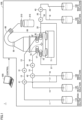
- FIG. 1 is a diagram schematically showing purification apparatus 1 according to the present embodiment.
- Fig. 2 is a diagram showing a construction of purification instrument 100 according to the present embodiment.
- purification apparatus 1 includes purification instrument 100 that purifies a target substance from a mixed sample and a control device 500.
- Control device 500 controls purification instrument 100.
- control device 500 controls purification instrument 100 to purify and collect the target substance from the mixed sample.
- Purification encompasses taking a target substance out of the mixed sample. In the present disclosure, "taking the target substance out of the mixed sample” may simply be referred to as “purification of the sample.”
- seawater and sand collected from the sea or the seashore represent an exemplary "mixed sample.”
- any substance collected by purification apparatus 1 may be applicable as the target substance to be collected by purification apparatus 1.
- exemplary target substances include microplastic which is fine plastic particles having a size not larger than 5 mm.
- microplastic contained in seawater and sand collected from the sea or the seashore represents an exemplary target substance.
- Microplastic which is the target substance is an exemplary "specific sample" in the present disclosure.
- purification instrument 100 includes a container 50 where a mixed sample is accommodated, pipes 11 to 23, pumps 31 to 33, electromagnetic valves 41 to 43, introduction ports 1F and 2F, discharge ports 1E and 2E, a stirrer 71, a stirring bar 72, a discharge pipe 80, a decomposition solution reservoir 110, a heavy solution reservoir 120, a rinse solution reservoir 130, waste solution reservoirs 140 and 150, a filter 210, a supernatant reservoir 215, and a casing 300.
- purification instrument 100 in the present embodiment includes two introduction ports of introduction ports 1F and 2F, it may include only a single introduction port.
- purification instrument 100 includes two discharge ports of discharge ports 1E and 2E, it may include only a single discharge port.
- Casing 300 surrounds a circumference of container 50.
- Casing 300 in the present embodiment includes a casing 300B arranged on a rear surface of container 50, a casing 300R arranged on the right of container 50, and a casing 300L arranged on the left of container 50.
- Casing 300 represents an exemplary "wall portion" in the present disclosure.
- a vertical direction when container 50 is installed is referred to as a "Z-axis direction.”
- a direction in which casing 300B extends when casing 300B is viewed from a side of a positive direction of the Z-axis direction is referred to as an "X-axis direction.”
- a direction in which casing 300L or casing 300R extends when casing 300L or casing 300R is viewed from the side of the positive direction of the Z-axis direction is referred to as a "Y-axis direction.”
- Each of the X-axis direction and the Y-axis direction is a direction perpendicular to the Z-axis direction.
- the positive direction of a Z axis in each figure may be referred to as an "upper side” and a negative direction of the Z axis may be referred to as a "lower side”
- the positive direction of an X axis may be referred to as a "right side” and the negative direction of the X axis may be referred to as a "left side”
- the positive direction of a Y axis may be referred to as a "front side” and the negative direction of the Y axis may be referred to as a "rear side.”
- Casing 300 may include an upper casing that covers an upper surface of the container. As shown in Fig. 2 , casing 300B is provided with passage holes 310, 320, and 330 for arrangement of respective pumps 31, 32, and 33.
- Container 50 includes a first member 51 and a second member 52 located above first member 51.
- Container 50 is dividable into first member 51 and second member 52.
- a user puts a mixed sample in the inside of first member 51 by removing second member 52 from first member 51.
- First member 51 and second member 52 are fixed in a connected state by a fixing tool (not shown) or the like.
- Container 50 is in a shape extending in the Z-axis direction. More specifically, first member 51 of container 50 is formed in a shape of a column with a circular bottom surface. Since first member 51 of container 50 is in the columnar shape, purification apparatus 1 in the present embodiment achieves improvement in efficiency in processing for stirring the mixed sample accommodated in container 50. In other words, since first member 51 of container 50 is in the columnar shape, uniform stirring of the mixed sample accommodated in the inside of container 50 is facilitated.
- the bottom surface of container 50 is not limited to the circular surface but may be in another shape such as a polygonal shape or an oval shape.
- Container 50 in the present embodiment is formed of glass.
- container 50 is transparent, and a user can externally visually recognize the mixed sample accommodated in container 50.
- the user can externally check occurrence of clogging or the like in introduction port 1F or 2F or discharge port 1E or 2E in container 50 in the present embodiment.
- Pipe 11 connects decomposition solution reservoir 110 and electromagnetic valve 41 to each other.
- Pipe 12 connects electromagnetic valve 41 and pump 31 to each other.
- Pipe 13 connects pump 31 and introduction port 2F to each other.
- Introduction port 2F is provided in an outer circumferential portion of container 50. Decomposition solution reservoir 110 and introduction port 2F of container 50 are thus connected to each other through pipes 11, 12, and 13 with electromagnetic valve 41 and pump 31 being interposed.
- Pipe 14 connects heavy solution reservoir 120 and electromagnetic valve 42 to each other.
- Pipe 15 connects electromagnetic valve 42 and pump 32 to each other.
- Pipe 16 connects pump 32 and introduction port 1F to each other.
- Port 62 is provided in the outer circumferential portion of container 50. Heavy solution reservoir 120 and introduction port 1F of container 50 are thus connected to each other through pipes 14, 15, and 16 with electromagnetic valve 42 and pump 32 being interposed.
- Pipe 17 connects rinse solution reservoir 130 and electromagnetic valve 41 to each other.
- electromagnetic valve 41 is connected to decomposition solution reservoir 110 through pipe 11, it is connected also to rinse solution reservoir 130 through pipe 17.
- Rinse solution reservoir 130 and introduction port 2F of container 50 are thus connected to each other through pipes 17, 12, and 13 with electromagnetic valve 41 and pump 31 being interposed.
- Pipe 18 connects rinse solution reservoir 130 and electromagnetic valve 42 to each other.
- electromagnetic valve 42 is connected to heavy solution reservoir 120 through pipe 14, it is connected also to rinse solution reservoir 130 through pipe 18.
- Rinse solution reservoir 130 and introduction port 1F of container 50 are thus connected to each other through pipes 18, 15, and 16 with electromagnetic valve 42 and pump 32 being interposed.
- Pipe 19 connects waste solution reservoir 140 and electromagnetic valve 43 to each other.
- Pipe 20 connects electromagnetic valve 43 and pump 33 to each other.
- Pipe 21 connects pump 33 and discharge port 1E to each other.
- Discharge port 1E is provided in the outer circumferential portion of container 50. Waste solution reservoir 140 and discharge port 1E of container 50 are thus connected to each other through pipes 19, 20, and 21 with electromagnetic valve 43 and pump 33 being interposed.
- Pipe 22 connects discharge port 2E and port 64 to each other.
- Discharge port 2E is provided in the outer circumferential portion of container 50.
- pump 33 is connected to discharge port 1E of container 50 through pipe 21, it is connected also to discharge port 2E of container 50 through pipe 22.
- Waste solution reservoir 140 and discharge port 2E of container 50 are thus connected to each other through pipes 19, 20, and 22 with electromagnetic valve 43 and pump 33 being interposed.
- Pipe 23 connects waste solution reservoir 150 and electromagnetic valve 43 to each other.
- electromagnetic valve 43 is connected to waste solution reservoir 140 through pipe 19, it is connected also to waste solution reservoir 150 through pipe 23.
- Waste solution reservoir 150 and discharge port 1E of container 50 are thus connected to each other through pipes 23, 20, and 21 with electromagnetic valve 43 and pump 33 being interposed.
- Waste solution reservoir 150 and discharge port 2E of container 50 are connected to each other through pipes 23, 20, and 22 with electromagnetic valve 43 and pump 33 being interposed.
- a decomposition solution for treatment of a contaminant is stored in decomposition solution reservoir 110.
- the "contaminant” refers to a foreign matter in the mixed sample, other than a target substance to be collected.
- an exemplary "contaminant” includes an organic contaminant having a property of an organic substance. Any “decomposition solution” may be applicable so long as the contaminant is decomposed therewith.
- the "decomposition solution” decomposes an organic contaminant.
- An exemplary “decomposition solution” includes an oxidizing agent such as oxygenated water (H 2 O 2 ) and a mixture of oxygenated water (H 2 O 2 ) and iron (II) oxide (FeO).
- exemplary "organic contaminants” include a scrap piece of wood mixed in seawater or sand and planktons.
- a heavy solution for separation of a mixed sample based on a specific gravity difference is stored in heavy solution reservoir 120. Any heavy solution may be applicable so long as the “heavy solution” separates the mixed sample based on the specific gravity difference.
- the "heavy solution” allows an inorganic contaminant having a property of an inorganic substance to settle based on the specific gravity difference.
- Exemplary “heavy solutions” include sodium chloride (NaCl), sodium iodide (NaI), and zinc chloride (ZnCl 2 ).
- exemplary “inorganic contaminants” include sand, glass, and stone.
- a specific gravity of the "heavy solution” is set to be greater than a specific gravity of the target substance to be collected by purification apparatus 1 and to be smaller than a specific gravity of the "inorganic contaminant.”
- the "heavy solution” should only be greater in specific gravity than microplastic and should only be smaller in specific gravity than sand, glass, stone, and the like.
- the specific gravity of the "heavy solution” should only be set approximately to 1.5 to 1.7.
- a rinse solution for cleaning of the inside of container 50 is stored in rinse solution reservoir 130. Any rinse solution may be applicable so long as the inside of container 50 is cleaned with the "rinse solution.”
- An exemplary “rinse solution” includes water. The "rinse solution” plays a role to clean the inside of container 50 and a role to dilute the decomposition solution introduced into container 50.
- a waste solution discharged from container 50 such as the heavy solution, the rinse solution, and sea water contained in the mixed sample is stored in waste solution reservoirs 140 and 150.
- Pump 31 introduces the decomposition solution in decomposition solution reservoir 110 or the rinse solution in rinse solution reservoir 130 into container 50 through introduction port 2F under the control by control device 500.
- Pump 32 introduces the heavy solution in heavy solution reservoir 120 or the rinse solution in rinse solution reservoir 130 into container 50 through introduction port 1F under the control by control device 500.
- Pump 33 discharges the waste solution in container 50 through discharge port 1E or discharge port 2E to waste solution reservoir 140 or waste solution reservoir 150 under the control by control device 500.
- Electromagnetic valve 41 switches a reservoir to be connected to introduction port 2F between decomposition solution reservoir 110 and rinse solution reservoir 130 under the control by control device 500.
- Electromagnetic valve 42 switches a reservoir to be connected to introduction port 1F between heavy solution reservoir 120 and rinse solution reservoir 130 under the control by control device 500.
- Electromagnetic valve 43 switches a path to be connected to discharge ports 1E and 2E between a path between waste solution reservoir 140 and discharge ports 1E and 2E of container 50 (a path through pipes 19, 20, and 21 or a path through pipes 19, 20, and 22) and a path between waste solution reservoir 150 and discharge ports 1E and 2E of container 50 (a path through pipes 23, 20, and 21 or a path through pipes 23, 20, and 22) under the control by control device 500.
- the decomposition solution in decomposition solution reservoir 110 or the rinse solution in rinse solution reservoir 130 suctioned by pump 31 is introduced into container 50 through introduction port 2F.
- the heavy solution in heavy solution reservoir 120 or the rinse solution in rinse solution reservoir 130 suctioned by pump 32 is introduced into container 50 through introduction port 1F.
- the waste solution in container 50 suctioned by pump 33 is discharged to waste solution reservoir 140 or waste solution reservoir 150 through discharge ports 1E and 2E.
- a filter (not shown) is provided not to allow discharge from container 50, of a target substance contained in the mixed sample.
- the filter is a mesh having a mesh size small enough to trap microplastic to be collected.
- the filter (mesh) is, for example, a wire gauze made of steel use stainless (SUS) or a membrane filter made of polytetrafluoroethylene (PTFE) (Teflon TM ).
- the mesh size of the filter (mesh) should be small enough not to allow passage therethrough of a particle having a size of 0.1 to 5.0 mm, and the mesh size is preferably approximately 0.1 mm.
- Introduction ports 1F and 2F and discharge ports 1E and 2E may collectively be referred to as the "port" below.
- Stirrer 71 is, for example, a magnetic constant-temperature stirrer, and arranged below container 50. Stirrer 71 generates magnetic force under the control by control device 500 to rotate stirring bar 72 provided in container 50. Stirring bar 72 stirs the mixed sample in container 50 by rotation or vibration upon receiving magnetic force from stirrer 71.
- stirrer 71 keeps a temperature of the mixed sample in container 50 constant by heating container 50 from below container 50 under the control by control device 500.
- a temperature of stirrer 71 is set approximately to 60°C to 70°C, and fluid in container 50 heated by stirrer 71 in accordance with a setting temperature is kept at approximately 50°C.
- Discharge pipe 80 is connected to a discharge port 55 provided at an uppermost portion of container 50, and a supernatant of the mixed sample that flows over container 50 is discharged therethrough to the outside.
- Filter 210 collects the target substance to be collected that is contained in the supernatant of the mixed sample discharged through discharge pipe 80 by filtering the supernatant. The supernatant that has passed through filter 210 is collected in supernatant reservoir 215.
- Filter 210 is a mesh having a mesh size small enough to trap microplastic to be collected.
- Filter 210 (mesh) is, for example, a wire gauze made of SUS or a membrane filter made of PTFE.
- the mesh size (size) of filter 210 should be small enough not to allow passage therethrough of a particle having a size of 0.1 to 5.0 mm, and the mesh size is preferably approximately 0.1 mm.
- Control device 500 may be implemented by a general-purpose computer or a dedicated computer for controlling purification instrument 100.
- Control device 500 controls pumps 31 to 33, electromagnetic valves 41 to 43, and stirrer 71 in purification instrument 100.
- control device 500 has electric power provided to pumps 31 to 33 to drive motors (not shown) to thereby open and close valves (not shown). Pumps 3 1 to 33 thus suction or deliver various types of fluid.
- Control device 500 has electric power provided to electromagnetic valves 41 to 43 to open and close the valves (not shown). Electromagnetic valves 41 to 43 thus switch a path through which various types of fluid pass.
- Control device 500 has electric power provided to stirrer 71 to drive a motor (not shown) to thereby rotate stirring bar 72 in container 50 with magnetic force. Furthermore, control device 500 has electric power provided to stirrer 71 to drive a heater (not shown) to apply certain heat to container 50.
- control device 500 includes, as main hardware elements thereof, a computing device 501, a memory 502, a communication device 503, a display device 504, an input device 505, a data reading device 506, and a storage 510.
- Computing device 501 is a computer that reads a program (for example, a control program 511 and an operating system (OS) 513) stored in storage 510 and develops the read program on memory 502 to execute the same.
- computing device 501 performs purification processing (which will be described later with reference to Fig. 4 ) for controlling purification instrument 100 by executing control program 511.
- Computing device 501 is implemented, for example, by a central processing unit (CPU), a field programmable gate array (FPGA), a graphics processing unit (GPU), a multi processing unit (MPU), or the like.
- Computing device 501 may be implemented by processing circuitry.
- Memory 502 provides a storage area where a program code or a work memory is temporarily stored in execution of any program by computing device 501.
- Memory 502 is implemented by a volatile memory such as a dynamic random access memory (DRAM) or a static random access memory (SRAM) or a non-volatile memory such as a read only memory (ROM) or a flash memory.
- DRAM dynamic random access memory
- SRAM static random access memory
- ROM read only memory
- flash memory non-volatile memory
- Communication device 503 transmits and receives data to and from another device over a network (not shown).
- Communication device 503 is in conformity with any communication scheme such as Ethernet ® , wireless local area network (LAN), and Bluetooth ® .
- Display device 504 is implemented, for example, by a liquid crystal display (LCD), and shows a program design screen or an alert screen on the occurrence of an abnormal condition.
- LCD liquid crystal display
- Input device 505 is implemented, for example, by a keyboard, a mouse, or the like, and used for input of design information by a user in design of a program.
- Input device 505 may include a start switch for starting purification processing by computing device 501.
- Data reading device 506 reads data stored in a storage medium 507.
- a storage medium 507 Any other storage medium such as a compact disc (CD), a digital versatile disc (DVD), or a universal serial bus (USB) memory may be applicable so long as various types of data can be stored in storage medium 507.
- CD compact disc
- DVD digital versatile disc
- USB universal serial bus
- Storage 510 provides a storage area where various types of data required for purification processing or the like are stored.
- Storage 510 is implemented, for example, by a non-volatile memory device such as a hard disk drive (HDD) or a solid state drive (SSD).
- Control program 511, control data 512, and operating system (OS) 513 are stored in storage 510.
- Control program 511 is a program in which contents of purification processing are described, and executed by computing device 501.
- Control program 511 may be designed by a user with the use of input device 505, read from storage medium 507 by data reading device 506, or obtained through the network from another device such as a server by communication device 503.
- Control data 512 is data used in execution of control program 511 by computing device 501.
- control data 512 includes data such as a setting value for control of each of pumps 31 to 33, electromagnetic valves 41 to 43, and stirrer 71.
- Control data 512 may be inputted by a user with the use of input device 505, read from storage medium 507 by data reading device 506, or obtained through the network from another device such as a server by communication device 503.
- OS 513 provides a basic function for computing device 501 to perform various types of processing.
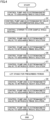
- Fig. 4 is a flowchart of purification processing performed by purification apparatus 1 according to the present embodiment. Each step shown in Fig. 4 is performed by execution of OS 513 and control program 511 by computing device 501 of control device 500. "S” in the drawings is used as abbreviation of "STEP".
- a user introduces a mixed sample into container 50 of purification apparatus 1.
- the user removes the first member from the second member to open container 50 to introduce the mixed sample into container 50.
- the user performs a start operation with the use of input device 505 of control device 500 to start control of purification instrument 100 by control device 500.
- control device 500 When control device 500 starts control of purification instrument 100, as shown in Fig. 4 , control device 500 controls pump 33 and electromagnetic valve 43 to discharge the waste solution in container 50 to waste solution reservoir 150 through pipes 20 to 23 and ports 63 and 64 (S1). Microplastic or the like to be collected that is contained in the mixed sample remains in container 50 without being discharged to the outside, owing to the filter provided in the inside of ports 63 and 64.
- Control device 500 then deactivates pump 33 on a discharge side and controls pump 31 and electromagnetic valve 41 to introduce the decomposition solution in decomposition solution reservoir 110 into container 50 through pipes 11 to 13 and port 61 (S2).
- Control device 500 then controls stirrer 71 to rotate stirring bar 72 provided in container 50 to stir the mixed sample while certain heat is applied to container 50 (S3).
- a temperature of container 50 and a rotation speed and a rotation time period of stirring bar 72 are set in advance by the user.
- oxidation treatment with an oxidizing agent is performed and an organic contaminant contained in the mixed sample is decomposed.
- heating is not necessarily required during stirring of the mixed sample, decomposition by oxidation treatment tends to be accelerated by the temperature of the mixed sample maintained constant by heating.
- Control device 500 then controls pump 33 and electromagnetic valve 43 to discharge the waste solution in container 50 included in the mixed sample in which the organic contaminant has been decomposed to waste solution reservoir 150 through pipes 20 to 23 and ports 63 and 64 (S4). Microplastic or the like to be collected that is contained in the mixed sample remains in container 50 without being discharged to the outside, owing to the filter provided in the inside of ports 63 and 64.
- Control device 500 then deactivates pump 33 on the discharge side and controls pump 31 and electromagnetic valve 41 to introduce the rinse solution in rinse solution reservoir 130 into container 50 through pipes 17, 12, and 13 and port 61 to clean the inside of container 50 (S5). At this time, control device 500 controls an amount of suction by pump 31 to introduce the rinse solution in an amount set in advance by the user into container 50.
- Control device 500 then controls pump 33 and electromagnetic valve 43 to discharge the waste solution in container 50 into which the rinse solution has been introduced to waste solution reservoir 150 through pipes 20 to 23 and ports 63 and 64 (S6).
- the inside of container 50 is thus cleaned with the rinse solution.
- Microplastic or the like to be collected that is contained in the mixed sample remains in container 50 without being discharged to the outside, owing to the filter provided in the inside of ports 63 and 64.
- control device 500 may let the mixed sample stand as it is for a prescribed period (for example, for one day) to dry the mixed sample.
- Control device 500 then controls pump 32 and electromagnetic valve 42 to introduce the heavy solution in heavy solution reservoir 120 into container 50 through pipes 14 to 16 and port 62 (S7). At this time, control device 500 controls the amount of suction by pump 32 to introduce the heavy solution in an amount set in advance by the user into container 50.
- control device 500 lets the mixed sample stand as it is for a prescribed period (for example, for one day) (S8). As the heavy solution is thus introduced into the mixed sample in container 50 and let stand, an inorganic contaminant contained in the mixed sample settles around the bottom of container 50 owing to the specific gravity difference.
- Control device 500 then again controls pump 32 and electromagnetic valve 42 to again introduce the heavy solution in heavy solution reservoir 120 into container 50 through pipes 14 to 16 and port 62 (S9). At this time, control device 500 controls the amount of suction by pump 32 to introduce the heavy solution in the amount set in advance by the user into container 50. As the heavy solution is thus introduced again into the mixed sample in container 50, a fluid level of the mixed sample separated based on the specific gravity gradually rises in container 50 and the supernatant of the mixed sample soon reaches discharge port 55 of container 50. Then, the supernatant of the mixed sample is discharged to the outside through discharge port 55 and discharge pipe 80.
- the supernatant of the mixed sample discharged through discharge pipe 80 is filtered by filter 210, and only the waste solution is collected in supernatant reservoir 215.
- Microplastic which is the target substance lighter in specific gravity than the heavy solution remains at filter 210.
- control device 500 After microplastic is collected as a result of purification of the mixed sample, control device 500 has container 50 cleaned as post-treatment. Specifically, control device 500 controls pump 33 and electromagnetic valve 43 to discharge the waste solution in container 50 from which microplastic has been collected to waste solution reservoir 140 through pipes 19 to 22 and ports 63 and 64 (S10).
- Control device 500 then deactivates pump 33 on the discharge side and controls pump 32 and electromagnetic valve 42 to introduce the rinse solution in rinse solution reservoir 130 into container 50 through pipes 18, 15, and 16 and port 62 to clean the inside of container 50 (S11). At this time, control device 500 controls the amount of suction by pump 32 to introduce the rinse solution in the amount set in advance by the user into container 50.
- Control device 500 then controls pump 33 and electromagnetic valve 43 to discharge the waste solution in container 50 into which the rinse solution has been introduced to waste solution reservoir 140 through pipes 19 to 22 and ports 63 and 64 (S12). The inside of container 50 is thus cleaned with the rinse solution.
- control device 500 automatically has the decomposition solution and the heavy solution introduced into the mixed sample accommodated in container 50 at appropriate timing for an appropriate time period, or has the waste solution discharged from container 50. Therefore, the user himself/herself does not have to introduce the decomposition solution and the heavy solution into container 50 or to discharge the waste solution from container 50. Thus, time and efforts by the user are not required, there is no possibility of variation in accuracy in collection of microplastic depending on skills of the user, and the user can accurately purify the mixed sample without spending time and efforts.
- control device 500 after microplastic is collected, control device 500 has used container 50 automatically cleaned. Therefore, the user himself/herself does not have to clean container 50.
- the mixed sample is seawater, sand, or the like.
- Seawater, sand, or the like taken from the nature may contain a contaminant which may cause clogging of introduction port 1F or 2F and discharge port 1E or 2E.
- the mixed sample contains the contaminant larger than the inner diameter of introduction port 1F or 2F and discharge port 1E or 2E, the contaminant may clog a portion of connection between the port and the container. Consequently, a flow of the heavy solution, the decomposition solution, the rinse solution, the waste solution, or the like may be blocked.
- Purification apparatus 1 automatically performs purification processing at appropriate timing for an appropriate time period under the control by control device 500 unless an abnormal condition occurs in purification apparatus 1.
- the purification apparatus can perform the purification processing without requiring an operation or intervention by the user for each type of processing.
- purification apparatus 1 When an abnormal condition such as clogging occurs in at least one of introduction ports 1F and 2F and discharge ports 1E and 2E during the purification processing, purification apparatus 1 is unable to perform normal purification processing.
- the purification processing proceeds with the abnormal condition being maintained in at least one of introduction ports 1F and 2F and discharge ports 1E and 2E, the user recognizes that the purification processing automatically normally proceeds, and hence long time is required before the user is aware of occurrence of the abnormal condition.
- purification apparatus 1 checking works for checking a state of the port may be carried out.
- Purification apparatus 1 according to the present embodiment is constructed to simplify the works for checking the port.
- a construction of introduction ports 1F and 2F and discharge ports 1E and 2E in purification apparatus 1 according to the present embodiment will be described below with reference to Figs. 5 and 6 .
- introduction ports 1F and 2F and discharge ports 1E and 2E are arranged at positions displaced toward one end in the outer circumferential surface of container 50, so that the checking works are simplified.
- the outer circumferential surface of container 50 is a surface that surrounds the axial direction of container 50.
- a side surface of container 50 corresponds to the outer circumferential surface.
- Fig. 5 is a first diagram for illustrating arrangement of introduction ports 1F and 2F and discharge ports 1E and 2E according to the present embodiment.
- Fig. 5 shows container 50 and casing 300 when viewed from the side of the negative direction of the Z axis. Therefore, Fig. 5 shows a circular shape which is the shape of the bottom surface of first member 51 of container 50.
- casing 300R On the side of the positive direction of the X axis of container 50, casing 300R which is a part of casing 300 is arranged. On the side of the negative direction of the X axis of container 50, casing 300L which is a part of casing 300 is arranged. Furthermore, on the side of the negative direction of the Y axis of container 50, casing 300B which is a part of casing 300 is arranged. On the side of the positive direction of the Y axis of container 50, casing 300 is not arranged. In other words, casing 300 is provided with an opening 300P on the side of the positive direction of the Y axis of container 50.
- An end P1 is an end of the outer circumferential surface of container 50 when container 50 is viewed from the side of the negative direction of the Z axis. End P1 is the end at a position closest to opening 300P in the outer circumferential surface of container 50. As shown in Fig. 5 , introduction ports 1F and 2F and discharge ports 1E and 2E are arranged at positions displaced toward end P1 in the outer circumferential surface of container 50.
- introduction ports 1F and 2F and discharge ports 1E and 2E are arranged in a first region Rg1 in the outer circumferential surface of container 50.
- First region Rg1 is one region when a region of the outer circumferential surface of container 50 is divided into two parts, a boundary between which is defined by a line Ln1 that passes through a center point CP1 in the shape of the bottom surface of container 50.
- first region Rg1 is the region on the side of the positive direction of the Y axis in the outer circumferential surface of container 50.
- a second region Rg2, on the other hand, is a region on the side of the negative direction of the Y axis in the outer circumferential surface of container 50.
- Introduction ports 1F and 2F and discharge ports 1E and 2E are arranged in a semicircle of the circular shape of container 50 when viewed from the negative direction of the Z axis.
- an angle Ag1 of intersection between a line that connects discharge port 1E and center point CP1 to each other and a line that connects discharge port 2E and center point CP1 to each other is 120 degrees. Any angle Ag1 may be applicable so long as it is smaller than 180 degrees.
- container 50 included in purification apparatus 1 in the present embodiment arrangement of all of introduction ports 1F and 2F and discharge ports 1E and 2E is thus displaced toward end P1 in the outer circumferential surface of container 50.
- the state of all of introduction ports 1F and 2F and discharge ports 1E and 2E is thus visually recognizable at once simply by viewing container 50 from the side opposed to end P1. In other words, the user can check at a glance, the state of each of introduction ports 1F and 2F and discharge ports 1E and 2E. Therefore, container 50 included in purification apparatus 1 in the present embodiment can simplify the works for checking introduction ports 1F and 2F and discharge ports 1E and 2E.
- introduction ports 1F and 2F and discharge ports 1E and 2E are arranged in the order of discharge port 1E, introduction port 1F, introduction port 2F, and discharge port 2E from the side of the negative direction of the X axis along the outer circumferential surface of container 50.
- introduction ports 1F and 2F are arranged between discharge port 1E and discharge port 2E along the outer circumferential surface of container 50.
- Container 50 can thus suppress, when any one of discharge port 1E and discharge port 2E is clogged by the contaminant, concentration of the contaminant in the port which is not clogged.
- the contaminant is concentrated in the vicinity of discharge port 1E due to suction by pump 33. Consequently, the contaminant is concentrated also in discharge port 2E arranged in the vicinity of discharge port 1E, and clogging may be caused in a linked manner.
- discharge port 1E and discharge port 2E are located at positions distant from each other. Therefore, even when any one discharge port is clogged, clogging in the other discharge port in a linked manner can be suppressed.
- Fig. 6 is a second diagram for illustrating arrangement of introduction ports 1F and 2F and discharge ports 1E and 2E according to the present embodiment.
- Fig. 6 shows container 50 when viewed from the side of the positive direction of the Y axis.
- Fig. 6 shows container 50 when end P1 is viewed from a position of opening 300P provided in casing 300.
- Introduction ports 1F and 2F and discharge ports 1E and 2E are thus arranged at positions opposed to opening 300P. Therefore, container 50 in the present embodiment can simplify the works for checking introduction ports 1F and 2F and discharge ports 1E and 2E; simply by viewing introduction ports 1F and 2F and discharge ports 1E and 2E through opening 300P, they are checked.
- a height HE1 at which discharge port 1E is connected to container 50 is lower than a height HF 1 at which introduction port 1F is connected to container 50.
- discharge port 1E is arranged on the side of the negative direction of the Z axis of introduction port 1F.
- Discharge port 2E is connected to container 50 at a position at height HE1, similarly to discharge port 1E.
- Introduction port 2F is connected to container 50 at a position at height HF1, similarly to introduction port 1F.
- height HE1 at which discharge ports 1E and 2E are arranged in the outer circumferential surface of container 50 is different from height HF1 at which introduction ports 1F and 2F are arranged in the outer circumferential surface of container 50.
- the user can thus recognize whether a port is the introduction port or the discharge port, based on a difference in height at which the port is arranged, and connection of a pipe to a wrong port can be suppressed.
- height HE1 at which discharge ports 1E and 2E are arranged is lower than height HF 1 at which introduction ports 1F and 2F are arranged, so that discharge of the waste solution in container 50 can be smoothed.
- discharge ports 1E and 2E are arranged at the positions close to the bottom surface, so that the waste solution in container 50 tends to be guided to discharge ports 1E and 2E.
- Figs. 5 and 6 illustrate the construction in which container 50 is columnar.
- Container 50 may be in another shape instead of the columnar shape.
- Fig. 7 is a first diagram for illustrating arrangement of introduction ports 1F and 2F and discharge ports 1E and 2E according to a modification.
- Fig. 7 shows container 50 and casing 300 in the modification when viewed from the side of the negative direction of the Z axis.
- container 50 in the modification has the bottom surface in a quadrangular shape.
- container 50 in the modification is in a shape of a quadrangular prism having the Z axis as the axial direction.
- each of introduction ports 1F and 2F and discharge ports 1E and 2E is arranged at a position displaced toward end P1 in the outer circumferential surface of container 50. More specifically, each of introduction ports 1F and 2F and discharge ports 1E and 2E is arranged in a surface Sf1 opposed to opening 300P in a side surface of the quadrangular prism.
- introduction ports 1F and 2F and discharge ports 1E and 2E are thus visually recognizable at once simply by viewing container 50 from the side opposed to end P1. Therefore, container 50 included in purification apparatus 1 in the modification can simplify the works for checking introduction ports 1F and 2F and discharge ports 1E and 2E.
- Fig. 8 is a second diagram for illustrating arrangement of introduction ports 1F and 2F and discharge ports 1E and 2E according to the modification.
- Fig. 8 shows container 50 when viewed from the side of the positive direction of the Y axis.
- height HE1 at which discharge ports 1E and 2E are arranged in the outer circumferential surface of container 50 is lower than height HF 1 at which introduction ports 1F and 2F are arranged in the outer circumferential surface of container 50.
- the user can recognize whether or not a port is the introduction port or the discharge port, based on the difference in height at which the port is arranged, and connection of a pipe to a wrong port can be suppressed. Since discharge ports 1E and 2E are arranged at positions close to the bottom surface, the waste solution in container 50 tends to be guided to discharge ports 1E and 2E.
- a container is included in a purification apparatus that purifies a specific sample from a mixed sample.
- the mixed sample is accommodated.
- the container has a shape extending in an axial direction.
- the container has an outer circumferential surface.
- the container includes an introduction port for introduction into the container, of a decomposition solution for treatment of a contaminant contained in the mixed sample, a heavy solution for separation of the mixed sample based on a specific gravity difference, or a rinse solution for cleaning of the container, and a first discharge port for discharge of a waste solution from the container.
- the introduction port and the first discharge port are both arranged at positions displaced toward one end position on the outer circumferential surface of the container.
- the outer circumferential surface includes a first region and a second region, a boundary between which is defined by a line that passes through a center point in a shape of a cross section with respect to the axial direction of the container.
- the introduction port and the first discharge port are arranged in the first region.
- a height of the first discharge port on the outer circumferential surface is lower than a height of the introduction port on the outer circumferential surface.
- discharge of the waste solution in the container can be smoothed.
- a second discharge port for discharge of the waste solution from the container is further provided.
- the introduction port is arranged between the first discharge port and the second discharge port along the outer circumferential surface.
- a purification apparatus is a purification apparatus that purifies a mixed sample.
- the purification apparatus includes a container for separation of the mixed sample with a heavy solution based on a specific gravity difference, a decomposition solution reservoir that holds a decomposition solution, a heavy solution reservoir that holds the heavy solution, and a rinse solution reservoir that holds a rinse solution.
- the container has a shape extending in an axial direction.
- the container has an outer circumferential surface.
- the container includes an introduction port for introduction into the container, of a decomposition solution for treatment of a contaminant contained in the mixed sample, a heavy solution for separation of the mixed sample based on a specific gravity difference, or a rinse solution for cleaning of the container, and a first discharge port for discharge of a waste solution from the container.
- the introduction port and the first discharge port are both arranged at positions displaced toward one end position on the outer circumferential surface of the container.
- a wall portion that surrounds a circumference of the container is further provided.
- the wall portion is provided with an opening.
- the introduction port and the first discharge port are arranged at positions opposed to the opening.
- 1 purification apparatus 1E, 2E discharge port; 1F, 2F introduction port; 11 to 23 pipe; 31 to 33 pump; 41 to 43 electromagnetic valve; 50 container; 51 first member; 52 second member; 55 discharge port; 61 to 64 port; 71 stirrer; 72 stirring bar; 80 discharge pipe; 100 purification instrument; 110 decomposition solution reservoir; 120 heavy solution reservoir; 130 rinse solution reservoir; 140, 150 waste solution reservoir; 210 filter; 215 supernatant reservoir; 300 casing; 300P opening; 310, 320, 330 passage hole; 500 control device; 501 computing device; 502 memory; 503 communication device; 504 display device; 505 input device; 506 data reading device; 507 storage medium; 510 storage; 511 control program; 512 control data; Ag1 angle; CP1 center point; HE1, HF1 height; Ln1 line; P1 end; Rg1 first region; Rg2 second region; Sf1 surface
Landscapes
- Chemical & Material Sciences (AREA)
- Life Sciences & Earth Sciences (AREA)
- Health & Medical Sciences (AREA)
- Engineering & Computer Science (AREA)
- General Physics & Mathematics (AREA)
- Pathology (AREA)
- Physics & Mathematics (AREA)
- Analytical Chemistry (AREA)
- Biochemistry (AREA)
- General Health & Medical Sciences (AREA)
- Immunology (AREA)
- Environmental & Geological Engineering (AREA)
- Water Supply & Treatment (AREA)
- Hydrology & Water Resources (AREA)
- Organic Chemistry (AREA)
- Medicinal Chemistry (AREA)
- Biomedical Technology (AREA)
- Molecular Biology (AREA)
- Mechanical Engineering (AREA)
- Sampling And Sample Adjustment (AREA)
- Separation Of Solids By Using Liquids Or Pneumatic Power (AREA)
- Apparatus Associated With Microorganisms And Enzymes (AREA)
Abstract
Description
- The present disclosure relates to a container and a purification apparatus that purifies a sample.
- A technique to collect a target substance by purification of the target substance from a mixed sample has conventionally been known. For example, NPL 1 discloses a method of purifying and collecting microplastic from aquatic sediments. NPL 1 describes introduction of a heavy solution through a pipe connected to a lower portion of a container for collection of microplastic.
- NPL 1: "A novel, highly efficient method for the separation and quantification of plastic particles in sediments of aquatic environments," [Searched on December 10, 2021], the Internet <URL:https://aslopubs.onlinelibrary.wiley.com/doi/epdf/10.4319/lom.2012.10.524>
- In purification of a target substance from a mixed sample in a container, a heavy solution, a rinse, or the like should be introduced into the container and a waste solution should be discharged to the outside of the container. Therefore, a pipe for introduction and a pipe for discharge may be connected to the container included in a purification apparatus.
- When an abnormal condition such as clogging occurs in at least one of the pipe for introduction and the pipe for discharge, an unfavorable situation such as inability to discharge the waste solution in purification processing is caused. Though checking works for checking whether or not the abnormal condition has occurred in each of the pipe for introduction and the pipe for discharge are required, such checking works have been bothersome.
- The present disclosure was made to solve the problem described above, and an object thereof is to provide a container included in a purification apparatus that purifies a sample, the container simplifying works for checking a pipe for introduction and a pipe for discharge.
- A container according to one aspect of the present disclosure is included in a purification apparatus that purifies a specific sample from a mixed sample. In the container, the mixed sample is accommodated. The container has a shape extending in an axial direction. The container has an outer circumferential surface. The container includes an introduction port for introduction into the container, of a decomposition solution for treatment of a contaminant contained in the mixed sample, a heavy solution for separation of the mixed sample based on a specific gravity difference, or a rinse solution for cleaning of the container, and a first discharge port for discharge of a waste solution from the container. When the container is viewed from the axial direction, the introduction port and the first discharge port are both arranged at positions displaced toward one end position on the outer circumferential surface of the container.
- According to the present disclosure, the introduction port and the first discharge port are located at positions displaced toward one end in the outer circumferential surface of the container. Therefore, a state of both of the introduction port and the first discharge port can be checked at a glance simply by viewing the container from a position opposed to one end, and hence works for checking the introduction port and the first discharge port can be simplified.
-
-
Fig. 1 is a diagram schematically showing a purification apparatus according to the present embodiment. -
Fig. 2 is a diagram showing a construction of a purification instrument according to the present embodiment. -
Fig. 3 is a diagram for illustrating a hardware configuration of the purification apparatus according to the present embodiment. -
Fig. 4 is a flowchart of purification processing performed by the purification apparatus according to the present embodiment. -
Fig. 5 is a first diagram for illustrating arrangement of an introduction port and a discharge port according to the present embodiment. -
Fig. 6 is a second diagram for illustrating arrangement of the introduction port and the discharge port according to the present embodiment. -
Fig. 7 is a first diagram for illustrating arrangement of the introduction port and the discharge port according to a modification. -
Fig. 8 is a second diagram for illustrating arrangement of the introduction port and the discharge port according to the modification. - The present embodiment will be described in detail with reference to the drawings. The same or corresponding elements in the drawings have the same reference characters allotted and description thereof will not be repeated in principle.
- A main construction of a
purification apparatus 1 and apurification instrument 100 according to the present embodiment will be described with reference toFigs. 1 and2 .Fig. 1 is a diagram schematically showingpurification apparatus 1 according to the present embodiment.Fig. 2 is a diagram showing a construction ofpurification instrument 100 according to the present embodiment. - As shown in
Fig. 1 ,purification apparatus 1 includespurification instrument 100 that purifies a target substance from a mixed sample and acontrol device 500.Control device 500controls purification instrument 100. Inpurification apparatus 1 according to the present embodiment,control device 500controls purification instrument 100 to purify and collect the target substance from the mixed sample. "Purification" encompasses taking a target substance out of the mixed sample. In the present disclosure, "taking the target substance out of the mixed sample" may simply be referred to as "purification of the sample." - Anything containing a target substance to be collected may be applicable as a "mixed sample." Exemplary "mixed samples" include seawater and sand collected from the sea or the seashore and processed products such as food and cosmetics. In the present embodiment, seawater and sand collected from the sea or the seashore represent an exemplary "mixed sample."
- Any substance collected by
purification apparatus 1 may be applicable as the target substance to be collected bypurification apparatus 1. Exemplary target substances include microplastic which is fine plastic particles having a size not larger than 5 mm. In the present embodiment, microplastic contained in seawater and sand collected from the sea or the seashore represents an exemplary target substance. Microplastic which is the target substance is an exemplary "specific sample" in the present disclosure. - As shown in
Figs. 1 and2 ,purification instrument 100 includes acontainer 50 where a mixed sample is accommodated,pipes 11 to 23,pumps 31 to 33,electromagnetic valves 41 to 43,introduction ports discharge ports stirrer 71, astirring bar 72, adischarge pipe 80, adecomposition solution reservoir 110, aheavy solution reservoir 120, arinse solution reservoir 130,waste solution reservoirs filter 210, asupernatant reservoir 215, and acasing 300. Thoughpurification instrument 100 in the present embodiment includes two introduction ports ofintroduction ports purification instrument 100 includes two discharge ports ofdischarge ports -
Casing 300 surrounds a circumference ofcontainer 50. Casing 300 in the present embodiment includes acasing 300B arranged on a rear surface ofcontainer 50, acasing 300R arranged on the right ofcontainer 50, and acasing 300L arranged on the left ofcontainer 50.Casing 300 represents an exemplary "wall portion" in the present disclosure. - In
Fig. 2 , a vertical direction whencontainer 50 is installed is referred to as a "Z-axis direction." A direction in whichcasing 300B extends whencasing 300B is viewed from a side of a positive direction of the Z-axis direction is referred to as an "X-axis direction." A direction in whichcasing 300L orcasing 300R extends whencasing 300L orcasing 300R is viewed from the side of the positive direction of the Z-axis direction is referred to as a "Y-axis direction." Each of the X-axis direction and the Y-axis direction is a direction perpendicular to the Z-axis direction. The positive direction of a Z axis in each figure may be referred to as an "upper side" and a negative direction of the Z axis may be referred to as a "lower side," the positive direction of an X axis may be referred to as a "right side" and the negative direction of the X axis may be referred to as a "left side," and the positive direction of a Y axis may be referred to as a "front side" and the negative direction of the Y axis may be referred to as a "rear side." -
Casing 300 may include an upper casing that covers an upper surface of the container. As shown inFig. 2 ,casing 300B is provided withpassage holes 310, 320, and 330 for arrangement ofrespective pumps -
Container 50 includes afirst member 51 and asecond member 52 located abovefirst member 51.Container 50 is dividable intofirst member 51 andsecond member 52. A user puts a mixed sample in the inside offirst member 51 by removingsecond member 52 fromfirst member 51.First member 51 andsecond member 52 are fixed in a connected state by a fixing tool (not shown) or the like. - The mixed sample is thus accommodated in the inside of
container 50.Container 50 according to the present embodiment is in a shape extending in the Z-axis direction. More specifically,first member 51 ofcontainer 50 is formed in a shape of a column with a circular bottom surface. Sincefirst member 51 ofcontainer 50 is in the columnar shape,purification apparatus 1 in the present embodiment achieves improvement in efficiency in processing for stirring the mixed sample accommodated incontainer 50. In other words, sincefirst member 51 ofcontainer 50 is in the columnar shape, uniform stirring of the mixed sample accommodated in the inside ofcontainer 50 is facilitated. The bottom surface ofcontainer 50 is not limited to the circular surface but may be in another shape such as a polygonal shape or an oval shape.Container 50 in the present embodiment is formed of glass. In other words,container 50 is transparent, and a user can externally visually recognize the mixed sample accommodated incontainer 50. Thus, the user can externally check occurrence of clogging or the like inintroduction port port container 50 in the present embodiment. -
Pipe 11 connectsdecomposition solution reservoir 110 andelectromagnetic valve 41 to each other.Pipe 12 connectselectromagnetic valve 41 and pump 31 to each other.Pipe 13 connectspump 31 andintroduction port 2F to each other.Introduction port 2F is provided in an outer circumferential portion ofcontainer 50.Decomposition solution reservoir 110 andintroduction port 2F ofcontainer 50 are thus connected to each other throughpipes electromagnetic valve 41 and pump 31 being interposed. -
Pipe 14 connectsheavy solution reservoir 120 andelectromagnetic valve 42 to each other.Pipe 15 connectselectromagnetic valve 42 and pump 32 to each other.Pipe 16 connectspump 32 andintroduction port 1F to each other. Port 62 is provided in the outer circumferential portion ofcontainer 50.Heavy solution reservoir 120 andintroduction port 1F ofcontainer 50 are thus connected to each other throughpipes electromagnetic valve 42 and pump 32 being interposed. -
Pipe 17 connects rinsesolution reservoir 130 andelectromagnetic valve 41 to each other. In other words, whileelectromagnetic valve 41 is connected todecomposition solution reservoir 110 throughpipe 11, it is connected also to rinsesolution reservoir 130 throughpipe 17. Rinsesolution reservoir 130 andintroduction port 2F ofcontainer 50 are thus connected to each other throughpipes electromagnetic valve 41 and pump 31 being interposed. -
Pipe 18 connects rinsesolution reservoir 130 andelectromagnetic valve 42 to each other. In other words, whileelectromagnetic valve 42 is connected toheavy solution reservoir 120 throughpipe 14, it is connected also to rinsesolution reservoir 130 throughpipe 18. Rinsesolution reservoir 130 andintroduction port 1F ofcontainer 50 are thus connected to each other throughpipes electromagnetic valve 42 and pump 32 being interposed. -
Pipe 19 connectswaste solution reservoir 140 andelectromagnetic valve 43 to each other.Pipe 20 connectselectromagnetic valve 43 and pump 33 to each other.Pipe 21 connectspump 33 anddischarge port 1E to each other.Discharge port 1E is provided in the outer circumferential portion ofcontainer 50.Waste solution reservoir 140 and dischargeport 1E ofcontainer 50 are thus connected to each other throughpipes electromagnetic valve 43 and pump 33 being interposed. -
Pipe 22 connectsdischarge port 2E and port 64 to each other.Discharge port 2E is provided in the outer circumferential portion ofcontainer 50. In other words, whilepump 33 is connected to dischargeport 1E ofcontainer 50 throughpipe 21, it is connected also to dischargeport 2E ofcontainer 50 throughpipe 22.Waste solution reservoir 140 and dischargeport 2E ofcontainer 50 are thus connected to each other throughpipes electromagnetic valve 43 and pump 33 being interposed. -
Pipe 23 connectswaste solution reservoir 150 andelectromagnetic valve 43 to each other. In other words, whileelectromagnetic valve 43 is connected to wastesolution reservoir 140 throughpipe 19, it is connected also to wastesolution reservoir 150 throughpipe 23.Waste solution reservoir 150 and dischargeport 1E ofcontainer 50 are thus connected to each other throughpipes electromagnetic valve 43 and pump 33 being interposed.Waste solution reservoir 150 and dischargeport 2E ofcontainer 50 are connected to each other throughpipes electromagnetic valve 43 and pump 33 being interposed. - A decomposition solution for treatment of a contaminant is stored in
decomposition solution reservoir 110. The "contaminant" refers to a foreign matter in the mixed sample, other than a target substance to be collected. In the present embodiment, an exemplary "contaminant" includes an organic contaminant having a property of an organic substance. Any "decomposition solution" may be applicable so long as the contaminant is decomposed therewith. In the present embodiment, the "decomposition solution" decomposes an organic contaminant. An exemplary "decomposition solution" includes an oxidizing agent such as oxygenated water (H2O2) and a mixture of oxygenated water (H2O2) and iron (II) oxide (FeO). When seawater and sand are adopted as the "mixed sample," exemplary "organic contaminants" include a scrap piece of wood mixed in seawater or sand and planktons. - A heavy solution for separation of a mixed sample based on a specific gravity difference is stored in
heavy solution reservoir 120. Any heavy solution may be applicable so long as the "heavy solution" separates the mixed sample based on the specific gravity difference. In the present embodiment, the "heavy solution" allows an inorganic contaminant having a property of an inorganic substance to settle based on the specific gravity difference. Exemplary "heavy solutions" include sodium chloride (NaCl), sodium iodide (NaI), and zinc chloride (ZnCl2). When seawater and sand are adopted as the "mixed sample," exemplary "inorganic contaminants" include sand, glass, and stone. A specific gravity of the "heavy solution" is set to be greater than a specific gravity of the target substance to be collected bypurification apparatus 1 and to be smaller than a specific gravity of the "inorganic contaminant." For example, when microplastic is adopted as the target substance to be collected bypurification apparatus 1 and sand, glass, stone, and the like are adopted as the "inorganic contaminant," the "heavy solution" should only be greater in specific gravity than microplastic and should only be smaller in specific gravity than sand, glass, stone, and the like. Specifically, the specific gravity of the "heavy solution" should only be set approximately to 1.5 to 1.7. - A rinse solution for cleaning of the inside of
container 50 is stored in rinsesolution reservoir 130. Any rinse solution may be applicable so long as the inside ofcontainer 50 is cleaned with the "rinse solution." An exemplary "rinse solution" includes water. The "rinse solution" plays a role to clean the inside ofcontainer 50 and a role to dilute the decomposition solution introduced intocontainer 50. - A waste solution discharged from
container 50 such as the heavy solution, the rinse solution, and sea water contained in the mixed sample is stored inwaste solution reservoirs -
Pump 31 introduces the decomposition solution indecomposition solution reservoir 110 or the rinse solution in rinsesolution reservoir 130 intocontainer 50 throughintroduction port 2F under the control bycontrol device 500. -
Pump 32 introduces the heavy solution inheavy solution reservoir 120 or the rinse solution in rinsesolution reservoir 130 intocontainer 50 throughintroduction port 1F under the control bycontrol device 500. -
Pump 33 discharges the waste solution incontainer 50 throughdischarge port 1E or dischargeport 2E to wastesolution reservoir 140 orwaste solution reservoir 150 under the control bycontrol device 500. -
Electromagnetic valve 41 switches a reservoir to be connected tointroduction port 2F betweendecomposition solution reservoir 110 and rinsesolution reservoir 130 under the control bycontrol device 500. -
Electromagnetic valve 42 switches a reservoir to be connected tointroduction port 1F betweenheavy solution reservoir 120 and rinsesolution reservoir 130 under the control bycontrol device 500. -
Electromagnetic valve 43 switches a path to be connected to dischargeports waste solution reservoir 140 anddischarge ports pipes pipes waste solution reservoir 150 anddischarge ports pipes pipes control device 500. - The decomposition solution in
decomposition solution reservoir 110 or the rinse solution in rinsesolution reservoir 130 suctioned bypump 31 is introduced intocontainer 50 throughintroduction port 2F. The heavy solution inheavy solution reservoir 120 or the rinse solution in rinsesolution reservoir 130 suctioned bypump 32 is introduced intocontainer 50 throughintroduction port 1F. The waste solution incontainer 50 suctioned bypump 33 is discharged to wastesolution reservoir 140 orwaste solution reservoir 150 throughdischarge ports - In the inside of each of
introduction ports discharge ports container 50, of a target substance contained in the mixed sample. The filter is a mesh having a mesh size small enough to trap microplastic to be collected. The filter (mesh) is, for example, a wire gauze made of steel use stainless (SUS) or a membrane filter made of polytetrafluoroethylene (PTFE) (Teflon™). When microplastic is to be collected, the mesh size of the filter (mesh) should be small enough not to allow passage therethrough of a particle having a size of 0.1 to 5.0 mm, and the mesh size is preferably approximately 0.1 mm.Introduction ports discharge ports -
Stirrer 71 is, for example, a magnetic constant-temperature stirrer, and arranged belowcontainer 50.Stirrer 71 generates magnetic force under the control bycontrol device 500 to rotate stirringbar 72 provided incontainer 50. Stirringbar 72 stirs the mixed sample incontainer 50 by rotation or vibration upon receiving magnetic force fromstirrer 71. - Furthermore,
stirrer 71 keeps a temperature of the mixed sample incontainer 50 constant byheating container 50 from belowcontainer 50 under the control bycontrol device 500. A temperature ofstirrer 71 is set approximately to 60°C to 70°C, and fluid incontainer 50 heated bystirrer 71 in accordance with a setting temperature is kept at approximately 50°C. -
Discharge pipe 80 is connected to adischarge port 55 provided at an uppermost portion ofcontainer 50, and a supernatant of the mixed sample that flows overcontainer 50 is discharged therethrough to the outside. -
Filter 210 collects the target substance to be collected that is contained in the supernatant of the mixed sample discharged throughdischarge pipe 80 by filtering the supernatant. The supernatant that has passed throughfilter 210 is collected insupernatant reservoir 215.Filter 210 is a mesh having a mesh size small enough to trap microplastic to be collected. Filter 210 (mesh) is, for example, a wire gauze made of SUS or a membrane filter made of PTFE. When microplastic is to be collected, the mesh size (size) offilter 210 should be small enough not to allow passage therethrough of a particle having a size of 0.1 to 5.0 mm, and the mesh size is preferably approximately 0.1 mm. -
Control device 500 may be implemented by a general-purpose computer or a dedicated computer for controllingpurification instrument 100.Control device 500 controls pumps 31 to 33,electromagnetic valves 41 to 43, andstirrer 71 inpurification instrument 100. - Specifically,
control device 500 has electric power provided topumps 31 to 33 to drive motors (not shown) to thereby open and close valves (not shown). Pumps 3 1 to 33 thus suction or deliver various types of fluid. -
Control device 500 has electric power provided toelectromagnetic valves 41 to 43 to open and close the valves (not shown).Electromagnetic valves 41 to 43 thus switch a path through which various types of fluid pass. -
Control device 500 has electric power provided tostirrer 71 to drive a motor (not shown) to thereby rotate stirringbar 72 incontainer 50 with magnetic force. Furthermore,control device 500 has electric power provided tostirrer 71 to drive a heater (not shown) to apply certain heat tocontainer 50. - A hardware configuration of
purification apparatus 1 according to the present embodiment will be described with reference toFig. 3. Fig. 3 is a diagram for illustrating a hardware configuration ofpurification apparatus 1 according to the present embodiment. As shown inFig. 3 ,control device 500 includes, as main hardware elements thereof, acomputing device 501, amemory 502, acommunication device 503, adisplay device 504, aninput device 505, adata reading device 506, and astorage 510. -
Computing device 501 is a computer that reads a program (for example, acontrol program 511 and an operating system (OS) 513) stored instorage 510 and develops the read program onmemory 502 to execute the same. For example,computing device 501 performs purification processing (which will be described later with reference toFig. 4 ) for controllingpurification instrument 100 by executingcontrol program 511.Computing device 501 is implemented, for example, by a central processing unit (CPU), a field programmable gate array (FPGA), a graphics processing unit (GPU), a multi processing unit (MPU), or the like.Computing device 501 may be implemented by processing circuitry. -
Memory 502 provides a storage area where a program code or a work memory is temporarily stored in execution of any program by computingdevice 501.Memory 502 is implemented by a volatile memory such as a dynamic random access memory (DRAM) or a static random access memory (SRAM) or a non-volatile memory such as a read only memory (ROM) or a flash memory. -
Communication device 503 transmits and receives data to and from another device over a network (not shown).Communication device 503 is in conformity with any communication scheme such as Ethernet®, wireless local area network (LAN), and Bluetooth®. -
Display device 504 is implemented, for example, by a liquid crystal display (LCD), and shows a program design screen or an alert screen on the occurrence of an abnormal condition. -
Input device 505 is implemented, for example, by a keyboard, a mouse, or the like, and used for input of design information by a user in design of a program.Input device 505 may include a start switch for starting purification processing bycomputing device 501. -
Data reading device 506 reads data stored in astorage medium 507. Any other storage medium such as a compact disc (CD), a digital versatile disc (DVD), or a universal serial bus (USB) memory may be applicable so long as various types of data can be stored instorage medium 507. -
Storage 510 provides a storage area where various types of data required for purification processing or the like are stored.Storage 510 is implemented, for example, by a non-volatile memory device such as a hard disk drive (HDD) or a solid state drive (SSD).Control program 511,control data 512, and operating system (OS) 513 are stored instorage 510. -
Control program 511 is a program in which contents of purification processing are described, and executed by computingdevice 501.Control program 511 may be designed by a user with the use ofinput device 505, read fromstorage medium 507 bydata reading device 506, or obtained through the network from another device such as a server bycommunication device 503. -
Control data 512 is data used in execution ofcontrol program 511 by computingdevice 501. For example,control data 512 includes data such as a setting value for control of each of pumps 31 to 33,electromagnetic valves 41 to 43, andstirrer 71.Control data 512 may be inputted by a user with the use ofinput device 505, read fromstorage medium 507 bydata reading device 506, or obtained through the network from another device such as a server bycommunication device 503. -
OS 513 provides a basic function forcomputing device 501 to perform various types of processing. - Mixed sample purification processing performed by
purification apparatus 1 will now be described with reference toFig. 4. Fig. 4 is a flowchart of purification processing performed bypurification apparatus 1 according to the present embodiment. Each step shown inFig. 4 is performed by execution ofOS 513 andcontrol program 511 by computingdevice 501 ofcontrol device 500. "S" in the drawings is used as abbreviation of "STEP". - For preparation, a user introduces a mixed sample into
container 50 ofpurification apparatus 1. For example, the user removes the first member from the second member to opencontainer 50 to introduce the mixed sample intocontainer 50. Thereafter, the user performs a start operation with the use ofinput device 505 ofcontrol device 500 to start control ofpurification instrument 100 bycontrol device 500. - When
control device 500 starts control ofpurification instrument 100, as shown inFig. 4 ,control device 500 controls pump 33 andelectromagnetic valve 43 to discharge the waste solution incontainer 50 to wastesolution reservoir 150 throughpipes 20 to 23 and ports 63 and 64 (S1). Microplastic or the like to be collected that is contained in the mixed sample remains incontainer 50 without being discharged to the outside, owing to the filter provided in the inside of ports 63 and 64. -
Control device 500 then deactivates pump 33 on a discharge side and controls pump 31 andelectromagnetic valve 41 to introduce the decomposition solution indecomposition solution reservoir 110 intocontainer 50 throughpipes 11 to 13 and port 61 (S2). -
Control device 500 then controlsstirrer 71 to rotate stirringbar 72 provided incontainer 50 to stir the mixed sample while certain heat is applied to container 50 (S3). A temperature ofcontainer 50 and a rotation speed and a rotation time period of stirringbar 72 are set in advance by the user. As the mixed sample is thus stirred, oxidation treatment with an oxidizing agent is performed and an organic contaminant contained in the mixed sample is decomposed. Though heating is not necessarily required during stirring of the mixed sample, decomposition by oxidation treatment tends to be accelerated by the temperature of the mixed sample maintained constant by heating. -
Control device 500 then controls pump 33 andelectromagnetic valve 43 to discharge the waste solution incontainer 50 included in the mixed sample in which the organic contaminant has been decomposed towaste solution reservoir 150 throughpipes 20 to 23 and ports 63 and 64 (S4). Microplastic or the like to be collected that is contained in the mixed sample remains incontainer 50 without being discharged to the outside, owing to the filter provided in the inside of ports 63 and 64. -
Control device 500 then deactivates pump 33 on the discharge side and controls pump 31 andelectromagnetic valve 41 to introduce the rinse solution in rinsesolution reservoir 130 intocontainer 50 throughpipes control device 500 controls an amount of suction bypump 31 to introduce the rinse solution in an amount set in advance by the user intocontainer 50. -
Control device 500 then controls pump 33 andelectromagnetic valve 43 to discharge the waste solution incontainer 50 into which the rinse solution has been introduced towaste solution reservoir 150 throughpipes 20 to 23 and ports 63 and 64 (S6). The inside ofcontainer 50 is thus cleaned with the rinse solution. Microplastic or the like to be collected that is contained in the mixed sample remains incontainer 50 without being discharged to the outside, owing to the filter provided in the inside of ports 63 and 64. Thereafter,control device 500 may let the mixed sample stand as it is for a prescribed period (for example, for one day) to dry the mixed sample. -
Control device 500 then controls pump 32 andelectromagnetic valve 42 to introduce the heavy solution inheavy solution reservoir 120 intocontainer 50 throughpipes 14 to 16 and port 62 (S7). At this time,control device 500 controls the amount of suction bypump 32 to introduce the heavy solution in an amount set in advance by the user intocontainer 50. - Thereafter,
control device 500 lets the mixed sample stand as it is for a prescribed period (for example, for one day) (S8). As the heavy solution is thus introduced into the mixed sample incontainer 50 and let stand, an inorganic contaminant contained in the mixed sample settles around the bottom ofcontainer 50 owing to the specific gravity difference. -
Control device 500 then again controlspump 32 andelectromagnetic valve 42 to again introduce the heavy solution inheavy solution reservoir 120 intocontainer 50 throughpipes 14 to 16 and port 62 (S9). At this time,control device 500 controls the amount of suction bypump 32 to introduce the heavy solution in the amount set in advance by the user intocontainer 50. As the heavy solution is thus introduced again into the mixed sample incontainer 50, a fluid level of the mixed sample separated based on the specific gravity gradually rises incontainer 50 and the supernatant of the mixed sample soon reachesdischarge port 55 ofcontainer 50. Then, the supernatant of the mixed sample is discharged to the outside throughdischarge port 55 anddischarge pipe 80. - The supernatant of the mixed sample discharged through
discharge pipe 80 is filtered byfilter 210, and only the waste solution is collected insupernatant reservoir 215. Microplastic which is the target substance lighter in specific gravity than the heavy solution remains atfilter 210. - After microplastic is collected as a result of purification of the mixed sample,
control device 500 hascontainer 50 cleaned as post-treatment. Specifically,control device 500 controls pump 33 andelectromagnetic valve 43 to discharge the waste solution incontainer 50 from which microplastic has been collected towaste solution reservoir 140 throughpipes 19 to 22 and ports 63 and 64 (S10). -
Control device 500 then deactivates pump 33 on the discharge side and controls pump 32 andelectromagnetic valve 42 to introduce the rinse solution in rinsesolution reservoir 130 intocontainer 50 throughpipes control device 500 controls the amount of suction bypump 32 to introduce the rinse solution in the amount set in advance by the user intocontainer 50. -
Control device 500 then controls pump 33 andelectromagnetic valve 43 to discharge the waste solution incontainer 50 into which the rinse solution has been introduced towaste solution reservoir 140 throughpipes 19 to 22 and ports 63 and 64 (S12). The inside ofcontainer 50 is thus cleaned with the rinse solution. - As set forth above, according to
purification apparatus 1 according to the present embodiment,control device 500 automatically has the decomposition solution and the heavy solution introduced into the mixed sample accommodated incontainer 50 at appropriate timing for an appropriate time period, or has the waste solution discharged fromcontainer 50. Therefore, the user himself/herself does not have to introduce the decomposition solution and the heavy solution intocontainer 50 or to discharge the waste solution fromcontainer 50. Thus, time and efforts by the user are not required, there is no possibility of variation in accuracy in collection of microplastic depending on skills of the user, and the user can accurately purify the mixed sample without spending time and efforts. - Furthermore, according to
purification apparatus 1 according to the present embodiment, after microplastic is collected,control device 500 has usedcontainer 50 automatically cleaned. Therefore, the user himself/herself does not have to cleancontainer 50. - As described above, in
purification apparatus 1 in the present embodiment, the mixed sample is seawater, sand, or the like. Seawater, sand, or the like taken from the nature may contain a contaminant which may cause clogging ofintroduction port port introduction port port -
Purification apparatus 1 according to the present embodiment automatically performs purification processing at appropriate timing for an appropriate time period under the control bycontrol device 500 unless an abnormal condition occurs inpurification apparatus 1. In other words, the purification apparatus can perform the purification processing without requiring an operation or intervention by the user for each type of processing. - When an abnormal condition such as clogging occurs in at least one of
introduction ports discharge ports purification apparatus 1 is unable to perform normal purification processing. When the purification processing proceeds with the abnormal condition being maintained in at least one ofintroduction ports discharge ports - Therefore, in
purification apparatus 1, checking works for checking a state of the port may be carried out.Purification apparatus 1 according to the present embodiment is constructed to simplify the works for checking the port. A construction ofintroduction ports discharge ports purification apparatus 1 according to the present embodiment will be described below with reference toFigs. 5 and6 . Specifically, inpurification apparatus 1 in the present embodiment,introduction ports discharge ports container 50, so that the checking works are simplified. The outer circumferential surface ofcontainer 50 is a surface that surrounds the axial direction ofcontainer 50. Regardingcontainer 50 in a columnar shape, a side surface ofcontainer 50 corresponds to the outer circumferential surface. -
Fig. 5 is a first diagram for illustrating arrangement ofintroduction ports discharge ports Fig. 5 showscontainer 50 andcasing 300 when viewed from the side of the negative direction of the Z axis. Therefore,Fig. 5 shows a circular shape which is the shape of the bottom surface offirst member 51 ofcontainer 50. - On the side of the positive direction of the X axis of
container 50, casing 300R which is a part ofcasing 300 is arranged. On the side of the negative direction of the X axis ofcontainer 50,casing 300L which is a part ofcasing 300 is arranged. Furthermore, on the side of the negative direction of the Y axis ofcontainer 50,casing 300B which is a part ofcasing 300 is arranged. On the side of the positive direction of the Y axis ofcontainer 50, casing 300 is not arranged. In other words, casing 300 is provided with anopening 300P on the side of the positive direction of the Y axis ofcontainer 50. - An end P1 is an end of the outer circumferential surface of
container 50 whencontainer 50 is viewed from the side of the negative direction of the Z axis. End P1 is the end at a position closest to opening 300P in the outer circumferential surface ofcontainer 50. As shown inFig. 5 ,introduction ports discharge ports container 50. - Specifically,
introduction ports discharge ports container 50. First region Rg1 is one region when a region of the outer circumferential surface ofcontainer 50 is divided into two parts, a boundary between which is defined by a line Ln1 that passes through a center point CP1 in the shape of the bottom surface ofcontainer 50. In other words, first region Rg1 is the region on the side of the positive direction of the Y axis in the outer circumferential surface ofcontainer 50. A second region Rg2, on the other hand, is a region on the side of the negative direction of the Y axis in the outer circumferential surface ofcontainer 50.Introduction ports discharge ports container 50 when viewed from the negative direction of the Z axis. - More specifically, an angle Ag1 of intersection between a line that connects
discharge port 1E and center point CP1 to each other and a line that connectsdischarge port 2E and center point CP1 to each other is 120 degrees. Any angle Ag1 may be applicable so long as it is smaller than 180 degrees. - In
container 50 included inpurification apparatus 1 in the present embodiment, arrangement of all ofintroduction ports discharge ports container 50. The state of all ofintroduction ports discharge ports container 50 from the side opposed to end P1. In other words, the user can check at a glance, the state of each ofintroduction ports discharge ports container 50 included inpurification apparatus 1 in the present embodiment can simplify the works for checkingintroduction ports discharge ports - As shown in
Fig. 5 ,introduction ports discharge ports discharge port 1E,introduction port 1F,introduction port 2F, and dischargeport 2E from the side of the negative direction of the X axis along the outer circumferential surface ofcontainer 50. In other words,introduction ports discharge port 1E and dischargeport 2E along the outer circumferential surface ofcontainer 50. -
Container 50 can thus suppress, when any one ofdischarge port 1E and dischargeport 2E is clogged by the contaminant, concentration of the contaminant in the port which is not clogged. For example, whendischarge port 1E and dischargeport 2E are successively arranged in the outer circumferential surface ofcontainer 50 anddischarge port 1E is clogged, the contaminant is concentrated in the vicinity ofdischarge port 1E due to suction bypump 33. Consequently, the contaminant is concentrated also indischarge port 2E arranged in the vicinity ofdischarge port 1E, and clogging may be caused in a linked manner. Incontainer 50 in the present embodiment, dischargeport 1E and dischargeport 2E are located at positions distant from each other. Therefore, even when any one discharge port is clogged, clogging in the other discharge port in a linked manner can be suppressed. -
Fig. 6 is a second diagram for illustrating arrangement ofintroduction ports discharge ports Fig. 6 showscontainer 50 when viewed from the side of the positive direction of the Y axis. In other words,Fig. 6 showscontainer 50 when end P1 is viewed from a position ofopening 300P provided incasing 300.Introduction ports discharge ports opening 300P. Therefore,container 50 in the present embodiment can simplify the works for checkingintroduction ports discharge ports introduction ports discharge ports opening 300P, they are checked. - As shown in
Fig. 6 , a height HE1 at which dischargeport 1E is connected tocontainer 50 is lower than aheight HF 1 at whichintroduction port 1F is connected tocontainer 50. In other words, dischargeport 1E is arranged on the side of the negative direction of the Z axis ofintroduction port 1F.Discharge port 2E is connected tocontainer 50 at a position at height HE1, similarly to dischargeport 1E.Introduction port 2F is connected tocontainer 50 at a position at height HF1, similarly tointroduction port 1F. - Thus, in
container 50 in the present embodiment, height HE1 at which dischargeports container 50 is different from height HF1 at whichintroduction ports container 50. The user can thus recognize whether a port is the introduction port or the discharge port, based on a difference in height at which the port is arranged, and connection of a pipe to a wrong port can be suppressed. Furthermore, height HE1 at which dischargeports height HF 1 at whichintroduction ports container 50 can be smoothed. In other words,discharge ports container 50 tends to be guided to dischargeports -
Figs. 5 and6 illustrate the construction in whichcontainer 50 is columnar.Container 50, however, may be in another shape instead of the columnar shape. -
Fig. 7 is a first diagram for illustrating arrangement ofintroduction ports discharge ports Fig. 7 showscontainer 50 andcasing 300 in the modification when viewed from the side of the negative direction of the Z axis. As shown inFig. 7 ,container 50 in the modification has the bottom surface in a quadrangular shape. In other words,container 50 in the modification is in a shape of a quadrangular prism having the Z axis as the axial direction. - In the modification in
Fig. 7 as well, incontainer 50 included inpurification apparatus 1 in the modification, each ofintroduction ports discharge ports container 50. More specifically, each ofintroduction ports discharge ports - The state of all of
introduction ports discharge ports container 50 from the side opposed to end P1. Therefore,container 50 included inpurification apparatus 1 in the modification can simplify the works for checkingintroduction ports discharge ports -
Fig. 8 is a second diagram for illustrating arrangement ofintroduction ports discharge ports Fig. 8 showscontainer 50 when viewed from the side of the positive direction of the Y axis. As shown inFig. 8 , also incontainer 50 in the modification, height HE1 at which dischargeports container 50 is lower thanheight HF 1 at whichintroduction ports container 50. Thus, also in the modification, the user can recognize whether or not a port is the introduction port or the discharge port, based on the difference in height at which the port is arranged, and connection of a pipe to a wrong port can be suppressed. Sincedischarge ports container 50 tends to be guided to dischargeports - Illustrative embodiments described above are understood by a person skilled in the art as specific examples of aspects below.
- (Clause 1) A container according to one aspect is included in a purification apparatus that purifies a specific sample from a mixed sample. In the container, the mixed sample is accommodated. The container has a shape extending in an axial direction. The container has an outer circumferential surface. The container includes an introduction port for introduction into the container, of a decomposition solution for treatment of a contaminant contained in the mixed sample, a heavy solution for separation of the mixed sample based on a specific gravity difference, or a rinse solution for cleaning of the container, and a first discharge port for discharge of a waste solution from the container. When the container is viewed from the axial direction, the introduction port and the first discharge port are both arranged at positions displaced toward one end position on the outer circumferential surface of the container.
- According to the container described in
Clause 1, works for checking the introduction port and the first discharge port can be simplified. - (Clause 2) The outer circumferential surface includes a first region and a second region, a boundary between which is defined by a line that passes through a center point in a shape of a cross section with respect to the axial direction of the container. The introduction port and the first discharge port are arranged in the first region.
- According to the container described in Clause 2, a state of each of the introduction port and the first discharge port can be checked at a glance.
- (Clause 3) A height of the first discharge port on the outer circumferential surface is lower than a height of the introduction port on the outer circumferential surface.
- According to the container described in Clause 3, discharge of the waste solution in the container can be smoothed.
- (Clause 4) A second discharge port for discharge of the waste solution from the container is further provided. The introduction port is arranged between the first discharge port and the second discharge port along the outer circumferential surface.
- According to the container described in
Clause 4, even when any one of the first discharge port and the second discharge port is clogged, linked occurrence of clogging in the other discharge port can be suppressed. - (Clause 5) The container is columnar.
- According to the container described in
Clause 5, efficiency in processing for stirring the mixed sample accommodated in the container is improved. - (Clause 6) A purification apparatus according to one aspect is a purification apparatus that purifies a mixed sample. The purification apparatus includes a container for separation of the mixed sample with a heavy solution based on a specific gravity difference, a decomposition solution reservoir that holds a decomposition solution, a heavy solution reservoir that holds the heavy solution, and a rinse solution reservoir that holds a rinse solution. The container has a shape extending in an axial direction. The container has an outer circumferential surface. The container includes an introduction port for introduction into the container, of a decomposition solution for treatment of a contaminant contained in the mixed sample, a heavy solution for separation of the mixed sample based on a specific gravity difference, or a rinse solution for cleaning of the container, and a first discharge port for discharge of a waste solution from the container. When the container is viewed from the axial direction, the introduction port and the first discharge port are both arranged at positions displaced toward one end position on the outer circumferential surface of the container.
- According to the purification apparatus described in Clause 6, works for checking the introduction port and the first discharge port can be simplified.
- (Clause 7) A wall portion that surrounds a circumference of the container is further provided. The wall portion is provided with an opening. The introduction port and the first discharge port are arranged at positions opposed to the opening.
- According to the purification apparatus described in
Clause 7, works for checking the introduction port and the first discharge port can be simplified; simply by viewing the introduction port and the first discharge port through the opening, they can be checked. - It should be understood that the embodiment disclosed herein is illustrative and non-restrictive in every respect. The scope of the present invention is defined by the terms of the claims rather than the description of the embodiment above and is intended to include any modifications within the scope and meaning equivalent to the terms of the claims.
- 1 purification apparatus; 1E, 2E discharge port; 1F, 2F introduction port; 11 to 23 pipe; 31 to 33 pump; 41 to 43 electromagnetic valve; 50 container; 51 first member; 52 second member; 55 discharge port; 61 to 64 port; 71 stirrer; 72 stirring bar; 80 discharge pipe; 100 purification instrument; 110 decomposition solution reservoir; 120 heavy solution reservoir; 130 rinse solution reservoir; 140, 150 waste solution reservoir; 210 filter; 215 supernatant reservoir; 300 casing; 300P opening; 310, 320, 330 passage hole; 500 control device; 501 computing device; 502 memory; 503 communication device; 504 display device; 505 input device; 506 data reading device; 507 storage medium; 510 storage; 511 control program; 512 control data; Ag1 angle; CP1 center point; HE1, HF1 height; Ln1 line; P1 end; Rg1 first region; Rg2 second region; Sf1 surface
Claims (7)
- A container in which a mixed sample is accommodated, the container being included in a purification apparatus that purifies a specific sample from the mixed sample, the container having a shape extending in an axial direction, the container having an outer circumferential surface, the container comprising:an introduction port for introduction into the container, of a decomposition solution for treatment of a contaminant contained in the mixed sample, a heavy solution for separation of the mixed sample based on a specific gravity difference, or a rinse solution for cleaning of the container; anda first discharge port for discharge of a waste solution from the container, whereinwhen the container is viewed from the axial direction, the introduction port and the first discharge port are both arranged at positions displaced toward one end position on the outer circumferential surface of the container.
- The container according to claim 1, whereinthe outer circumferential surface includes a first region and a second region, a boundary between which is defined by a line that passes through a center point in a shape of a cross section with respect to the axial direction of the container, andthe introduction port and the first discharge port are arranged in the first region.
- The container according to claim 1, wherein
a height of the first discharge port on the outer circumferential surface is lower than a height of the introduction port on the outer circumferential surface. - The container according to claim 1, further comprising a second discharge port for discharge of the waste solution from the container, wherein
the introduction port is arranged between the first discharge port and the second discharge port along the outer circumferential surface. - The container according to claim 1, wherein the container is columnar.
- A purification apparatus that purifies a mixed sample, the purification apparatus comprising:a container for separation of the mixed sample with a heavy solution based on a specific gravity difference;a decomposition solution reservoir that holds a decomposition solution;a heavy solution reservoir that holds the heavy solution; anda rinse solution reservoir that holds a rinse solution, whereinthe container has a shape extending in an axial direction,the container has an outer circumferential surface,the container includesan introduction port for introduction of the decomposition solution, the heavy solution, or the rinse solution into the container, anda first discharge port for discharge of a waste solution from the container, andwhen the container is viewed from the axial direction, the introduction port and the first discharge port both are arranged at positions displaced toward one end position on the outer circumferential surface of the container.
- The purification apparatus according to claim 6, further comprising a wall portion that surrounds a circumference of the container, whereinthe wall portion is provided with an opening, andthe introduction port and the first discharge port are arranged at positions opposed to the opening.
Applications Claiming Priority (2)
| Application Number | Priority Date | Filing Date | Title |
|---|---|---|---|
| JP2021213099 | 2021-12-27 | ||
| PCT/JP2022/039626 WO2023127254A1 (en) | 2021-12-27 | 2022-10-25 | Container and purification apparatus |
Publications (2)
| Publication Number | Publication Date |
|---|---|
| EP4458471A1 true EP4458471A1 (en) | 2024-11-06 |
| EP4458471A4 EP4458471A4 (en) | 2025-11-19 |
Family
ID=86998649
Family Applications (1)
| Application Number | Title | Priority Date | Filing Date |
|---|---|---|---|
| EP22915488.5A Pending EP4458471A4 (en) | 2021-12-27 | 2022-10-25 | CONTAINER AND CLEANING DEVICE |
Country Status (5)
| Country | Link |
|---|---|
| US (1) | US20250026672A1 (en) |
| EP (1) | EP4458471A4 (en) |
| JP (1) | JP7722470B2 (en) |
| CN (1) | CN118338969A (en) |
| WO (1) | WO2023127254A1 (en) |
Family Cites Families (7)
| Publication number | Priority date | Publication date | Assignee | Title |
|---|---|---|---|---|
| JP4097440B2 (en) * | 2002-03-07 | 2008-06-11 | 文彦 中野 | Oil / water separation and recovery equipment |
| CN112004607B (en) * | 2017-12-09 | 2023-10-10 | 欧佩克修复技术有限公司 | Methods and equipment for separating substances from water |
| CN210279470U (en) * | 2019-06-03 | 2020-04-10 | 罗平金丰油脂有限公司 | Impurity removal device for vegetable seed cleaning and sorting machine |
| CN110773331B (en) * | 2019-09-30 | 2022-02-01 | 河南大学 | Enrichment device for separating micro-plastics in environmental soil and sediments |
| CN214234466U (en) * | 2020-11-24 | 2021-09-21 | 青岛浩海仪器有限公司 | Device for separating micro-plastics from sediments |
| CN112845522B (en) * | 2020-12-31 | 2024-01-05 | 华南理工大学 | An integrated device for efficient separation of microplastics in sediments and partial desorption of adsorbed pollutants and its use method |
| CN113686734B (en) * | 2021-08-17 | 2022-09-06 | 江南大学 | Integrated device and method for simulating micro plastic migration and target extraction |
-
2022
- 2022-10-25 JP JP2023570673A patent/JP7722470B2/en active Active
- 2022-10-25 WO PCT/JP2022/039626 patent/WO2023127254A1/en not_active Ceased
- 2022-10-25 EP EP22915488.5A patent/EP4458471A4/en active Pending
- 2022-10-25 US US18/715,233 patent/US20250026672A1/en active Pending
- 2022-10-25 CN CN202280079360.8A patent/CN118338969A/en active Pending
Also Published As
| Publication number | Publication date |
|---|---|
| EP4458471A4 (en) | 2025-11-19 |
| WO2023127254A1 (en) | 2023-07-06 |
| US20250026672A1 (en) | 2025-01-23 |
| JPWO2023127254A1 (en) | 2023-07-06 |
| JP7722470B2 (en) | 2025-08-13 |
| CN118338969A (en) | 2024-07-12 |
Similar Documents
| Publication | Publication Date | Title |
|---|---|---|
| EP4174468A1 (en) | Specimen refining device, analysis system, specimen refining method, and control program | |
| EP4458471A1 (en) | Container and purification apparatus | |
| EP4458473A1 (en) | Purifier | |
| EP4454759A1 (en) | Purification apparatus | |
| US12287263B2 (en) | Sample purification apparatus and analysis system | |
| EP4458474A1 (en) | Purification apparatus | |
| US20250026669A1 (en) | Purification apparatus and method of controlling purification apparatus | |
| EP4459256A1 (en) | Refining device and control method for refining device | |
| EP4603169A1 (en) | Recovery implement and recovery system | |
| US20250011203A1 (en) | Purification apparatus and control method | |
| JP3926777B2 (en) | Mud suction device | |
| WO2024079837A1 (en) | Treatment device |
Legal Events
| Date | Code | Title | Description |
|---|---|---|---|
| STAA | Information on the status of an ep patent application or granted ep patent |
Free format text: STATUS: THE INTERNATIONAL PUBLICATION HAS BEEN MADE |
|
| PUAI | Public reference made under article 153(3) epc to a published international application that has entered the european phase |
Free format text: ORIGINAL CODE: 0009012 |
|
| STAA | Information on the status of an ep patent application or granted ep patent |
Free format text: STATUS: REQUEST FOR EXAMINATION WAS MADE |
|
| 17P | Request for examination filed |
Effective date: 20240523 |
|
| AK | Designated contracting states |
Kind code of ref document: A1 Designated state(s): AL AT BE BG CH CY CZ DE DK EE ES FI FR GB GR HR HU IE IS IT LI LT LU LV MC ME MK MT NL NO PL PT RO RS SE SI SK SM TR |
|
| DAV | Request for validation of the european patent (deleted) | ||
| DAX | Request for extension of the european patent (deleted) | ||
| A4 | Supplementary search report drawn up and despatched |
Effective date: 20251020 |
|
| RIC1 | Information provided on ipc code assigned before grant |
Ipc: B03B 5/30 20060101AFI20251014BHEP Ipc: B01J 4/00 20060101ALI20251014BHEP Ipc: G01N 1/34 20060101ALI20251014BHEP Ipc: B01D 21/00 20060101ALI20251014BHEP Ipc: B01D 21/24 20060101ALI20251014BHEP Ipc: B03D 1/14 20060101ALI20251014BHEP Ipc: B29B 17/02 20060101ALI20251014BHEP |