EP4458442A2 - Verfahren zum installieren eines packungsabschnitts in einem mantelring - Google Patents
Verfahren zum installieren eines packungsabschnitts in einem mantelring Download PDFInfo
- Publication number
- EP4458442A2 EP4458442A2 EP24196022.8A EP24196022A EP4458442A2 EP 4458442 A2 EP4458442 A2 EP 4458442A2 EP 24196022 A EP24196022 A EP 24196022A EP 4458442 A2 EP4458442 A2 EP 4458442A2
- Authority
- EP
- European Patent Office
- Prior art keywords
- ferrule
- shell
- section
- cradle
- inlet opening
- Prior art date
- Legal status (The legal status is an assumption and is not a legal conclusion. Google has not performed a legal analysis and makes no representation as to the accuracy of the status listed.)
- Pending
Links
Images


Classifications
-
- B—PERFORMING OPERATIONS; TRANSPORTING
- B01—PHYSICAL OR CHEMICAL PROCESSES OR APPARATUS IN GENERAL
- B01J—CHEMICAL OR PHYSICAL PROCESSES, e.g. CATALYSIS OR COLLOID CHEMISTRY; THEIR RELEVANT APPARATUS
- B01J19/00—Chemical, physical or physico-chemical processes in general; Their relevant apparatus
- B01J19/30—Loose or shaped packing elements, e.g. Raschig rings or Berl saddles, for pouring into the apparatus for mass or heat transfer
-
- B—PERFORMING OPERATIONS; TRANSPORTING
- B01—PHYSICAL OR CHEMICAL PROCESSES OR APPARATUS IN GENERAL
- B01J—CHEMICAL OR PHYSICAL PROCESSES, e.g. CATALYSIS OR COLLOID CHEMISTRY; THEIR RELEVANT APPARATUS
- B01J19/00—Chemical, physical or physico-chemical processes in general; Their relevant apparatus
- B01J19/32—Packing elements in the form of grids or built-up elements for forming a unit or module inside the apparatus for mass or heat transfer
- B01J19/325—Attachment devices therefor, e.g. hooks, consoles, brackets
-
- B—PERFORMING OPERATIONS; TRANSPORTING
- B01—PHYSICAL OR CHEMICAL PROCESSES OR APPARATUS IN GENERAL
- B01D—SEPARATION
- B01D3/00—Distillation or related exchange processes in which liquids are contacted with gaseous media, e.g. stripping
-
- B—PERFORMING OPERATIONS; TRANSPORTING
- B01—PHYSICAL OR CHEMICAL PROCESSES OR APPARATUS IN GENERAL
- B01D—SEPARATION
- B01D3/00—Distillation or related exchange processes in which liquids are contacted with gaseous media, e.g. stripping
- B01D3/14—Fractional distillation or use of a fractionation or rectification column
- B01D3/26—Fractionating columns in which vapour and liquid flow past each other, or in which the fluid is sprayed into the vapour, or in which a two-phase mixture is passed in one direction
-
- B—PERFORMING OPERATIONS; TRANSPORTING
- B01—PHYSICAL OR CHEMICAL PROCESSES OR APPARATUS IN GENERAL
- B01D—SEPARATION
- B01D3/00—Distillation or related exchange processes in which liquids are contacted with gaseous media, e.g. stripping
- B01D3/14—Fractional distillation or use of a fractionation or rectification column
- B01D3/32—Other features of fractionating columns ; Constructional details of fractionating columns not provided for in groups B01D3/16 - B01D3/30
-
- B—PERFORMING OPERATIONS; TRANSPORTING
- B23—MACHINE TOOLS; METAL-WORKING NOT OTHERWISE PROVIDED FOR
- B23P—METAL-WORKING NOT OTHERWISE PROVIDED FOR; COMBINED OPERATIONS; UNIVERSAL MACHINE TOOLS
- B23P11/00—Connecting or disconnecting metal parts or objects by metal-working techniques not otherwise provided for
- B23P11/02—Connecting or disconnecting metal parts or objects by metal-working techniques not otherwise provided for by first expanding and then shrinking or vice versa, e.g. by using pressure fluids; by making force fits
-
- B—PERFORMING OPERATIONS; TRANSPORTING
- B23—MACHINE TOOLS; METAL-WORKING NOT OTHERWISE PROVIDED FOR
- B23P—METAL-WORKING NOT OTHERWISE PROVIDED FOR; COMBINED OPERATIONS; UNIVERSAL MACHINE TOOLS
- B23P15/00—Making specific metal objects by operations not covered by a single other subclass or a group in this subclass
-
- B—PERFORMING OPERATIONS; TRANSPORTING
- B23—MACHINE TOOLS; METAL-WORKING NOT OTHERWISE PROVIDED FOR
- B23P—METAL-WORKING NOT OTHERWISE PROVIDED FOR; COMBINED OPERATIONS; UNIVERSAL MACHINE TOOLS
- B23P19/00—Machines for simply fitting together or separating metal parts or objects, or metal and non-metal parts, whether or not involving some deformation; Tools or devices therefor so far as not provided for in other classes
- B23P19/10—Aligning parts to be fitted together
- B23P19/12—Alignment of parts for insertion into bores
-
- B—PERFORMING OPERATIONS; TRANSPORTING
- B01—PHYSICAL OR CHEMICAL PROCESSES OR APPARATUS IN GENERAL
- B01J—CHEMICAL OR PHYSICAL PROCESSES, e.g. CATALYSIS OR COLLOID CHEMISTRY; THEIR RELEVANT APPARATUS
- B01J2219/00—Chemical, physical or physico-chemical processes in general; Their relevant apparatus
- B01J2219/32—Details relating to packing elements in the form of grids or built-up elements for forming a unit of module inside the apparatus for mass or heat transfer
- B01J2219/322—Basic shape of the elements
- B01J2219/32203—Sheets
- B01J2219/32275—Mounting or joining of the blocks or sheets within the column or vessel
-
- B—PERFORMING OPERATIONS; TRANSPORTING
- B01—PHYSICAL OR CHEMICAL PROCESSES OR APPARATUS IN GENERAL
- B01J—CHEMICAL OR PHYSICAL PROCESSES, e.g. CATALYSIS OR COLLOID CHEMISTRY; THEIR RELEVANT APPARATUS
- B01J2219/00—Chemical, physical or physico-chemical processes in general; Their relevant apparatus
- B01J2219/32—Details relating to packing elements in the form of grids or built-up elements for forming a unit of module inside the apparatus for mass or heat transfer
- B01J2219/322—Basic shape of the elements
- B01J2219/32279—Tubes or cylinders
-
- B—PERFORMING OPERATIONS; TRANSPORTING
- B01—PHYSICAL OR CHEMICAL PROCESSES OR APPARATUS IN GENERAL
- B01J—CHEMICAL OR PHYSICAL PROCESSES, e.g. CATALYSIS OR COLLOID CHEMISTRY; THEIR RELEVANT APPARATUS
- B01J2219/00—Chemical, physical or physico-chemical processes in general; Their relevant apparatus
- B01J2219/32—Details relating to packing elements in the form of grids or built-up elements for forming a unit of module inside the apparatus for mass or heat transfer
- B01J2219/33—Details relating to the packing elements in general
- B01J2219/3306—Dimensions or size aspects
Definitions
- the present invention relates to the field of gas/liquid separation columns and their assembly and it relates more particularly to a method of installing a packing section in a shell in order to form said gas/liquid separation columns.
- Gas/liquid separation columns have been known for many years and can be used, for example, to separate different chemical elements that make up a homogeneous fluid, for example by distillation or absorption.
- the manufacture of a gas/liquid separation column includes in particular a step of inserting a plurality of packing sections into a shell.
- the packing sections are used in particular in columns to ensure the exchange of material and heat between a rising gas and a descending liquid.
- These packing sections which are notably formed by a superposition of several corrugated strips, are often called "packs".
- the packing sections are conventionally stacked on top of each other, if necessary with interposed separators, in order to participate in the separation of the components of the fluid on the axial dimension of the column.
- This force of gravity can even cause a slight deformation of the shell and make it complicated to center the packing section relative to an entry opening of the shell opposite which the packing section must be positioned before being pushed inside this shell.
- the present invention has as its main object a method according to claim 1.
- the ferrule advantageously and generally takes a cylindrical shape extending along the longitudinal direction, the latter being parallel to the axis of revolution of said cylinder. It is understood from the above, and from the horizontal mounting of the ferrule, that the longitudinal direction is substantially parallel to the ground on which the ferrule is installed during the method of installing the packing section.
- This particular arrangement of the ferrule relative to the ground facilitates the insertion of the packing section when the ferrule has a length, measured along a direction parallel to the longitudinal direction, and a diameter, corresponding to the diameter of the cylinder, equal to and/or greater than ten meters for example.
- such a method of installing a section of packing can also be applied to the installation of a section of packing on a shell whose length and/or diameter would be less than ten meters.
- the step of mounting the installation assistance device on the shell is carried out upstream of the positioning step and the pushing step.
- the installation assistance device is advantageously fixed in the vicinity of the inlet opening to assist in mounting the packing section in the shell, so as to ensure the correct positioning of these two elements relative to each other and reduce the risk of deformation of the shell and/or the packing section when pushing one into the other.
- the fixing is advantageously a removable fixing so that the installation assistance device can be removed once all of the packing sections are arranged inside the shell.
- the fixing of the installation assistance device is carried out by screwing between said installation assistance device and the tubular wall of the shell.
- the installation assistance device takes a first position in which the installation assistance device is secured to the ferrule and a second position in which the installation assistance device is detached from the ferrule.
- the packing section is positioned relative to the installation aid to facilitate insertion of the packing section into the shell, i.e. the installation aid is configured so that the packing section is properly centered when resting on the installation aid. In this way, it is possible to subsequently easily push the packing section into the shell and thus reduce frictional forces against the inner face of the tubular wall.
- a means for transporting the packing section maintains the packing section opposite the inlet opening at least until said packing section is positioned against the loading assistance device. the installation.
- the means of transport may in particular be formed by a device for inserting a packing section, which comprises both means for holding a packing section and means for pushing this packing section.
- the means of transport may also be a portable system of packing sections, independent of a pushing means.
- the device for assisting in installing a section of packing comprises a removable cone, the method for installing the section comprising a step of mounting a removable cone on the shell and at least one centering step during which the removable cone centers the section of packing relative to the inlet opening of the shell.
- the removable cone is fixed on an upper portion of the ferrule in the vicinity of the inlet opening.
- upper portion means a portion of the ferrule opposite the ground on which the ferrule rests relative to the lower part, this arrangement being assessed relative to a vertical direction substantially perpendicular to the longitudinal direction.
- the cradle has an at least partially circular section seen in a plane perpendicular to the longitudinal direction and falling within a circle of diameter identical to that in which the tubular wall of the shell is inscribed.
- the cradle extends in the extension of the shell, having a curvature similar to that of the shell.
- the cradle extends over at least 25% of the circumference of the inlet opening of the shell.
- the section of the cradle generally takes the shape of an arc of a circle, so as to extend over a portion of the circumference of the inlet opening. Due to the position in the lower part of the cradle, its only function is to ensure the vertical maintenance of the packing section for ensuring that the vertical position of this section is correct relative to the shell, the cradle may have a circumferential extent such that raised edges prevent the section of packing in place on the cradle from tilting laterally. More particularly, the cradle may extend over 33% of the circumference of the shell entry opening.
- the cradle has a longitudinal dimension, measured between the inlet opening of the shell and a free end of the cradle, which is between 75 and 150 mm.
- the longitudinal dimension, measured parallel to the axis of revolution of the cylinder forming the shell, is greater than 75 mm in order to allow sufficient force absorption to support the packing section during the positioning step and while waiting for the packing section to be pushed inside the shell.
- the longitudinal dimension is between 90 and 110 mm. Even more advantageously, the longitudinal dimension is 100 mm.
- the cradle comprises at least one metallic material.
- the cradle comprises stainless steel and/or aluminum.
- the fixing means is permanently arranged on the ferrule and configured to be able to cooperate with an attachment body of the device for assisting in the installation of the packing section.
- the fixing means is a weld bead between the device for assisting in installing the packing section and the ferrule.
- the installation assistance device comprises a removable cone, the attachment body being carried by the removable cone, the attachment body cooperating with the fixing means to secure the removable cone to the ferrule.
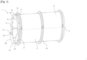
- a ferrule 1 is illustrated used during a method of installing a packing section 2 according to the invention, the packing section 2 being shown in the figure 2 .
- This method of installing the packing section 2 makes it possible to install a packing section 2 in the shell 1, in particular during installation in a shell arranged horizontally, by cleverly reducing the risk of deformation of the shell 1 during said method.
- the shell 1 extends mainly along a longitudinal direction L, thus having two longitudinal ends.
- the shell 1 is positioned horizontally during the installation process of the packing section 2, i.e. the longitudinal direction L extends substantially parallel to the ground on which the shell 1 is installed.
- the shell 1 comprises at least one tubular wall 4, which extends mainly along the longitudinal direction L, generally taking the shape of a right cylinder, the longitudinal direction L corresponding here to the main direction of extension of the tubular wall 4 and to its axis of revolution.
- a section of the tubular wall 4 seen in a plane perpendicular to the longitudinal direction L is substantially inscribed in a circle.
- the tubular wall 4 has an internal face 6 oriented towards the inside of the shell 1 and an external face 8 facing towards the outside of the shell 1.
- the internal face 6 of the tubular wall 4 helps to delimit a housing for at least one section of packing 2, installed in the shell 1 via the installation method according to the invention.
- the tubular wall 4 participates in delimiting an inlet opening 10 at one of the longitudinal ends of the shell 1.
- the inlet opening 10 corresponds to the opening through which the packing sections 2 are inserted into the shell 1 during said installation process.
- the ferrule 1 includes a bottom wall 12, visible on the figure 4 , arranged at the other longitudinal end of the shell 1, that is to say opposite the inlet opening 10. At least the first section of packing 2 installed in the shell 1 is positioned in the vicinity of the bottom wall, if necessary against the bottom wall 12.
- the packing section 2 as illustrated in the figures 2 And 3 , generally takes the form of a cylindrical body capable of being installed in the housing of the tubular wall 4.
- the lining section 2 has a peripheral edge 8 whose profile, seen in a plane perpendicular to the longitudinal direction L, is a circle whose diameter is equal to or substantially less than the diameter of the shell at the level of the internal face of the tubular wall 4.
- a packing section is notably constituted by a superposition of several corrugated and intersecting strips and the stacking of these sections within a shell makes it possible to ensure, during the operation of the gas/liquid separation column comprising this shell, the exchange of material and heat between a rising gas and a descending liquid.
- the packing sections are conventionally stacked on top of each other, if necessary with interposed separators. Obtaining a separation column thus involves inserting packing sections within the shell one after the other, via an appropriate insertion device during a method of installing packing sections.
- the method for installing a section of packing 2 in a shell 1 is carried out using a device 14 for assisting in installing a section of packing 2, which is more particularly arranged in the vicinity of the longitudinal end of the shell 1 forming the inlet opening 10.
- this installation assistance device 14 is a removable device, which is only fixed to the shell 1 during the method for inserting the section of packing into the shell, with the shell in a horizontal position, and which is subsequently removed, in particular when the shell returns to a vertical functional position.
- the ferrule 1 comprises at least one means 15 for fixing the installation assistance device 14 to the ferrule 1, this fixing means 15 being able, according to the variant embodiments of the invention, to be formed of an element permanently present on the ferrule 1 and in particular on the tubular wall 4 of the ferrule, and used only when the installation assistance device 14 must be fixed on the ferrule, or else to be formed by a weld bead made between the ferrule 1 and the installation assistance device 14, the weld bead being unsoldered in a second stage after insertion of the packing sections into the ferrule 1.
- this at least one fixing means 15 can for example take the form of a through orifice formed in the tubular wall 4 of the ferrule 1, the orifice being intended to receive a tightening assembly, for example a screw cooperating with a bolt to press against the tubular wall 4 an attachment body 17 of the installation assistance device 14 equipped with holes arranged opposite the fixing means 15 provided on the ferrule.
- a tightening assembly for example a screw cooperating with a bolt to press against the tubular wall 4 an attachment body 17 of the installation assistance device 14 equipped with holes arranged opposite the fixing means 15 provided on the ferrule.
- the at least one fixing means 15 can take the form of a weld bead formed between a longitudinal end of the tubular wall 4 and the installation assistance device 14.
- This weld bead is in particular produced in order to secure the installation assistance device 14 to the inlet opening 10 of the shell 1.
- the weld bead is the result of edge-to-edge welding between the installation assistance device 14 and the tubular wall 4.
- the installation assistance device 14 and the tubular wall 4 are positioned in contact with each other at an end edge, without overlapping either edge, at the time of welding between the installation assistance device 14 and the tubular wall 4.
- the installation assistance device 14 comprises a cradle 16 which extends in an extension of at least part of the tubular wall 4, from the inlet opening 10 along the longitudinal direction L opposite the bottom wall 12.
- the cradle 16 takes the form of an extension wall projecting from the tubular wall 4, in the vicinity of the longitudinal end of the shell 1 in which the inlet opening 10 is formed, opposite the bottom wall 12.
- the cradle 16 is in particular configured to receive and carry at least partially the packing section 2 during the installation method according to the invention, and in particular prior to its insertion within the shell.
- the cradle 16 is installed in the extension of a lower portion 18 of the shell 1, this lower portion 18 being assessed with respect to a vertical direction extending perpendicularly to the main extension plane of the ground on which said ferrule 1 is arranged. It is understood that the cradle 16 is arranged at the level of the lower portion 18 of the ferrule 1 in order to be able to rest the packing section 2 thereon and maintain it in position, facing the inlet opening 10, despite the gravitational force which tends to attract the packing section towards the ground.
- the cradle 16 can carry the packing section 2 so that it remains positioned facing the inlet opening 10 of the ferrule 1, in particular for the time that the means of transport used to bring the packing section into this position is disengaged from the packing section and that an appropriate pushing means is arranged to push this packing section into the ferrule.
- the cradle 16 has an at least partially circular section seen in a plane perpendicular to the longitudinal direction L and falling within a circle of diameter identical to that in which the tubular wall 4 of the shell 1 is inscribed. In other words, the curvature of the cradle 16 is substantially the same as the curvature of the tubular wall 4.
- the section of the cradle 16 generally takes the form of an arc of a circle, so as to extend over a portion of the circumference of the inlet opening 10. More particularly, the cradle 16 extends over at least 25% of the circumference of the inlet opening 10 of the shell 1, extending in particular on either side, advantageously symmetrically, of the lower portion of the shell, i.e. the portion of the shell closest to the ground on which this shell rests. In this way, the cradle provides support for the section of packing when the latter is released by the means of transport and the cradle prevents the section of packing from escaping laterally.
- the cradle 16 can be welded edge to edge on the ferrule 1, in the direct extension of the edge participating in delimiting the entry opening 10 of the ferrule 1, or else be fixed by reversible attachment means, via an attachment body 17 which is then intended to be in contact with the tubular wall 4 of the ferrule 1.
- the cradle comprises a support portion 19, forming the projecting part of the ferrule 1 and which has a free end 22 opposite the inlet opening 10.
- the attachment body 17 is pressed against one face of the tubular wall, here the external face of this tubular wall 4, without this however limiting the invention.
- the attachment body 17 has a longitudinal dimension making it possible to ensure sufficient coverage of the tubular wall and to allow stability of the entire cradle, and more particularly to allow the attachment means 15 to be held without tearing off the cradle when the lining section is resting on the support portion 19 of the cradle.
- the support portion 19 of the cradle has a longitudinal dimension, measured between the inlet opening 10 of the ferrule 1 and the free end 20, which is between 75 and 150 mm. It is understood here that the longitudinal dimension of the cradle 16 is at least 75 mm in order to allow the packing section 2 to be positioned correctly on the cradle 16 during the installation process. This longitudinal dimension also corresponds to at least 50% of a longitudinal dimension of the packing section 2. More particularly, the longitudinal dimension of the cradle may be between 90 and 110 mm, and be of the order of 100 mm.
- the cradle 16 may have a longitudinal end that is welded to the inlet opening 10 of the ferrule 1, this longitudinal end then being able to be unwelded at the end of the assembly process.
- the removal of the cradle 16 may also be carried out by cutting out the inlet opening 10 of the ferrule 1. It is thus understood that the cradle 16 does not comprise an attachment body as it could have been described above.
- the cradle 16 comprises at least one metallic material, which may notably consist of stainless steel and/or aluminum.
- This type of material thus optimizes the solidity of the cradle 16 and its ability to support the section of filling 2 during the installation process.
- the installation assistance device 14 may comprise a removable cone 22 configured to guide the assembly of the packing section 2 by centering said packing section 2 on the inlet opening 10.
- the removable cone 22 can be welded edge to edge on the ferrule 1, in the direct extension of the edge participating in delimiting the inlet opening 10 of the ferrule 1, or else be fixed by reversible fastening means, via a fastening body 17 which is then intended to be in contact with the tubular wall 4 of the ferrule 1.
- the removable cone 22 comprises a guide portion 21, forming the projecting part of the ferrule 1 and which has a free edge 24 opposite the inlet opening 10.
- the attachment body 17 is pressed against the external face of this tubular wall, without this however being limiting of the invention.
- the attachment body 17 has a longitudinal dimension which makes it possible to ensure sufficient coverage of the tubular wall 4 of the ferrule 1 and to allow stability of the entire removable cone 22, and more particularly to allow the attachment means 15 to be held without tearing off the removable cone when the packing section forces longitudinally against the removable cone to be centered.
- the removable cone 22 is installed at the inlet opening 10 of the ferrule 1, and the guide portion 21 of the removable cone 22 forms a truncated portion whose section is at least partially circular when viewed in a plane perpendicular to the longitudinal direction, this section tending to enlarge as one moves away from the inlet opening 10 and from the ferrule as a whole.
- the first section of the removable cone 22 is inscribed in a circle of larger diameter than the circle in which the second section of the removable cone 22 is inscribed. It is understood here that the removable cone 22 is arranged at the inlet opening 10 of the shell 1 so that, during the process of installing the packing section 2, the removable cone 22 guides the packing section 2 by centering it on the inlet opening 10.
- the removable cone 22 thus orients the packing section 2 so that an axis parallel to the longitudinal direction L and passing through the center of the circle in which the curvature of the external surface 8 of the packing section 2 is inscribed coincides with the axis of revolution of the tubular wall 4 of the shell 1.
- the removable cone 22 has a longitudinal end which is welded edge to edge with the edge of the ferrule delimiting the inlet opening 10 of the ferrule 1, this longitudinal end can then be unwelded from the ferrule at the end of the assembly process, that is to say once the packing sections are installed.
- the removal of the removable cone 22 can also be carried out by cutting the inlet opening 10 of the ferrule 1. It is thus understood that the removable cone 22 therefore does not comprise an attachment body as it could have been described above.
- the removable cone 22 extends over at least 50% of the circumference of the inlet opening 10 of the ferrule 1, and preferably over 67% of this circumference.
- the section of the removable cone 22 here generally takes the form of an arc of a circle, so as to extend over a portion of the circumference of the inlet opening 10. Such a circumferential extent of the removable cone 22 is sufficient to center the packing section 2 on the inlet opening 10, and it also makes it possible to install the removable cone 22 and the cradle 16 around the periphery of the inlet opening 10.
- the cradle 16 and the removable cone 22 extend one after the other so that their respective attachment bodies 17 together cover substantially the entire circumference of the inlet opening 10 of the ferrule 1.
- the removable cone 22 has a longitudinal dimension measured between the inlet opening 10 of the ferrule 1 and the free edge 24 of the removable cone 22 of between 30 and 50 mm. This dimension is in particular measured along a direction parallel to the longitudinal direction L, between the edge of the removable cone 22 in contact with the tubular wall 4 and a projection of the free edge 24 of the removable cone 22 on said direction.
- the longitudinal dimension is greater than 30 mm in order to be able to center the packing section 2 on the inlet opening 10 during the positioning step. More particularly, the longitudinal dimension of the truncated portion of the removable cone can be between 30 and 40 mm, and be of the order of 35 mm.
- the longitudinal dimension of the cradle 16 is advantageously greater than the longitudinal dimension of the removable cone 22.
- the function of the cradle is to provide possible support for the packing section 2 during the centering of said packing section 2 by the removable cone 22.
- the function of the cradle 16 is to support the packing section 2 between the moment when the transport means, used to bring the packing section opposite the inlet opening of the shell, releases the packing section and the moment when the pushing means, used to insert the packing section into the shell by a horizontal pushing movement, is in contact with the packing section. The release of the section takes place once the packing section 2 has been centered by means of the removable cone 22.
- the removable cone 22 comprises at least one metallic material.
- the metallic material may be stainless steel and/or aluminum.
- the removable cone 22 is elastically deformable between a centering position, under the constraint of the packing section, and a rest position which it tends to return to by actually recentering the packing section. This characteristic promotes the installation and centering of the packing section 2 on the inlet opening 10 by reducing the risk of degradation of the shell 1 and/or the packing section 2.
- each potential component of the installation assistance device 14, namely the cradle 16 and possibly the removable cone 22, may have an attachment body 17 intended to be pressed against the tubular wall of the ferrule to allow the removable attachment of the installation assistance device during the method of installing the packing section according to the invention.
- the device installation aid comprises a fastening body 17 which must be fixed to the tubular wall 4 of the ferrule.
- fixing holes are made through the plate forming the attachment body 17 to be arranged opposite the fixing means 15, more particularly here the orifices, present in the tubular portion in the vicinity of the inlet opening.
- a clamping assembly here not visible and for example of the screw-nut type, is then used to cooperate with the fixing holes of the attachment body 17 and the fixing means 15 of the ferrule, to make the cradle 16 and/or the removable cone 22 of the ferrule 1 integral.
- the ferrule 1 comprises several fixing means 15 arranged regularly around the periphery of the tubular wall, or as illustrated in the figure 5 , the ferrule 1 may comprise a single fixing means extending around the entire circumference of the ferrule 1 and formed by a weld bead.
- the ferrule 1 is installed horizontally in order to be able to mount the packing section 2 along the longitudinal direction L.
- the ferrule 1 is equipped with a device 14 for assisting in installing the packing section 2 comprising both a cradle 16 and a removable cone 22.
- a method for installing a packing section 2 implementing a device 14 for assisting in installing a packing section 2 comprising only the cradle 16 would not depart from the scope of the invention.
- the method comprises a step of mounting the installation assistance device 14 on the shell 1, during which the installation assistance device 14 is fixed in the vicinity of the inlet opening 10 of the shell 1, a step of positioning the packing section 2 opposite the inlet opening 10, in cooperation with the installation assistance device 14, and at least one pushing step during which the packing section 2 is pushed into the housing of the shell 1.
- the step of mounting the installation assistance device 14 on the shell 1 is carried out upstream of the positioning step and the pushing step.
- the installation assistance device 14 is advantageously fixed in the vicinity of the inlet opening 10 to assist in mounting the packing section 2 in the shell 1, so as to reduce the risk of deformation of the shell 1.
- the fixing of the installation assistance device 14 is carried out by screwing, or by welding if necessary, between said installation assistance device 14 and the tubular wall 4 of the shell 1, by fixing the cradle 16 to the tubular wall 4 then the removable cone 22 to said tubular wall 4, or vice versa.
- the assembly method thus comprises a step of assembly of the cradle 16 on the ferrule 1 during which the cradle 16 is fixed on a lower portion 18 of the tubular wall 4 of the ferrule 1 in the vicinity of the inlet opening 10, and a step of assembly of a removable cone 22 on an upper portion of the tubular wall 4 of the ferrule 1.
- each of these elements of the installation assistance device is carried out here in a similar manner, by arranging the attachment body 17 against the tubular wall 4 of the ferrule and leaving the support portion 19 of the cradle and/or the guide portion 21 of the removable cone projecting from the ferrule, then by adjusting the position so that the holes formed in the attachment body 17 are opposite the attachment means 15 of the ferrule, and finally by tightening the clamping assemblies provided for this purpose and passing through the attachment means 15 and the attachment body 17.
- the assembly of each of these elements of the installation assistance device 14 is done in a similar manner by welding the edge of the cradle 16 and of the removable cone 22 to the edge of the ferrule 1 participating in delimiting the entry opening 10.
- This edge-to-edge welding makes it possible to leave the support portion 19 of the cradle 16 and/or the guide portion 21 of the removable cone 22 protruding from the ferrule 1.
- the fixing of the installation assistance device 14 is removable, so that at the end of the method which will continue to be described, the installation assistance device 14 is detached from the ferrule 1.
- the installation assistance device 14, and a fortiori the cradle 16 and possibly removable cone 22, is able to take a first position in which the installation assistance device 14 is detached from the ferrule 1.
- the installation 14 is secured to the ferrule 1 and a second position in which the installation assistance device 14 is detached from the ferrule 1.
- the packing section 2 is positioned relative to the installation assistance device 14 to subsequently facilitate the insertion of the packing section 2 into the shell 1.
- the installation assistance device 14 makes it possible, for example, to center the packing section 2 on the inlet opening 10 so as to be able to easily push the packing section 2 into the shell 1 and thus reduce the friction forces against the internal face 6 of the tubular wall 4.
- a means 26 for transporting the packing section 2 positions the packing section 2 on the cradle 16 of the installation assistance device 14.
- the means of transport is independent of any pushing means implemented subsequently, but it should be noted that these means could be combined in a single installation without this departing from the context of the invention.
- the installation method also comprises a centering step during which, following the positioning step, simultaneously with it, or even where appropriate prior to it, the removable cone 22 participates in centering the packing section 2 relative to the inlet opening 10 of the shell 1.
- the packing section 2 is offset along the longitudinal direction L towards the bottom wall 12, the radial edge of said packing section 2 running along an internal surface of the removable cone 22 to be centered on the inlet opening 10.
- the centering step is carried out upstream of the positioning step, that is to say that the packing section 2 is first centered by the removable cone 22 on the inlet opening 10 of the ferrule 1 before being positioned on the cradle 16 of the ferrule 1, in anticipation of the pushing step.
- the positioning step makes it possible to switch from the centering step to the pushing step by ensuring that the packing section 2 is supported, in particular by avoiding a vertical movement of said guide section 2, after having been centered on the inlet opening 10 and before being pushed into the housing of the ferrule 1.
- This positioning step thus gives the time necessary to remove the transport means 26, which must be released so as not to hinder the insertion of the packing section 2, then bring a pushing means into contact with the packing section 2.
- the packing section 2 is moved along the longitudinal direction L towards the bottom wall 12 of the shell 1 during the pushing step.
- a pushing device 28 for the packing section 2 is provided for this purpose, capable of at least exerting sufficient force on the packing section 2 for it to move in the housing of the shell 1.
- the pushing device 28 is secured to the shell 1 upstream of the pushing step in order to allow, when the pushing device 28 moves the packing section 2 in the shell 1, to keep the shell 1 in position, reducing the risk of deformation of the tubular wall 4 and the shell 1.
- the method for installing a packing section 2 comprises a step of dismantling the installation assistance device 14, during which the cradle 16 and/or the removable cone 22 are separated from the shell. If necessary, once the packing sections 2 intended to be installed in the shell 1 have been installed, the installation assistance device 14 can be dismantled to be reassembled on another shell 1 in which packing sections 2 are to be installed.
- the installation assistance device 14 is dismantled by disconnecting the clamping assembly cooperating with the fixing means 15 and the attachment body 17, so that the installation assistance device 14 is no longer secured to the ferrule 1.
- the fixing means 15 remain visible on the ferrule 1 in the vicinity of the inlet opening 10.
- the orifices forming the fixing means 15 can therefore be plugged by sealing means ensuring the sealing of the gas/liquid separation column that the ferrule 1 helps to form.
- the step of dismantling the installation assistance device 14 may consist, in the variant of the invention in which the fixing means 15 takes the form of a weld bead, in an operation of desoldering the installation aid device 14 and/or cutting the inlet opening 10.
- the desoldering is first carried out, then a machining operation is carried out in order to make the longitudinal end of the ferrule 1 smooth around its periphery, such as a deburring operation for example. It is thus understood that no mark of the fixing of the installation aid device 14 is visible on the inlet opening 10 at the end of the method of installing the packing section 2.
- the installation assistance device 14 of a packing section 2 in the shell 1 is a clever solution for optimizing the installation of said packing section 2 in the shell 1.
- This installation assistance device 14 thus prevents the risks of deformation of the tubular wall 4 of the shell 1, by correctly positioning the packing section 2 relative to the inlet opening 10 of the shell 1.
- this installation assistance device 14 can be mounted and/or dismounted from a shell 1, making it possible to use a shell without a protruding appendage at the inlet opening in a gas/liquid separation column.
Landscapes
- Chemical & Material Sciences (AREA)
- Chemical Kinetics & Catalysis (AREA)
- Engineering & Computer Science (AREA)
- Mechanical Engineering (AREA)
- Physics & Mathematics (AREA)
- Thermal Sciences (AREA)
- Organic Chemistry (AREA)
- Gasket Seals (AREA)
- Filtering Of Dispersed Particles In Gases (AREA)
- Automatic Assembly (AREA)
- Sewage (AREA)
- Lining Or Joining Of Plastics Or The Like (AREA)
Applications Claiming Priority (2)
| Application Number | Priority Date | Filing Date | Title |
|---|---|---|---|
| FR2114214A FR3130629A1 (fr) | 2021-12-22 | 2021-12-22 | Procédé d’installation d’un tronçon de garnissage dans une virole. |
| EP22211458.9A EP4201497A1 (de) | 2021-12-22 | 2022-12-05 | Verfahren zum installieren eines packungsabschnitts in einem mantelring |
Related Parent Applications (1)
| Application Number | Title | Priority Date | Filing Date |
|---|---|---|---|
| EP22211458.9A Division EP4201497A1 (de) | 2021-12-22 | 2022-12-05 | Verfahren zum installieren eines packungsabschnitts in einem mantelring |
Publications (2)
| Publication Number | Publication Date |
|---|---|
| EP4458442A2 true EP4458442A2 (de) | 2024-11-06 |
| EP4458442A3 EP4458442A3 (de) | 2025-01-08 |
Family
ID=80786476
Family Applications (2)
| Application Number | Title | Priority Date | Filing Date |
|---|---|---|---|
| EP22211458.9A Pending EP4201497A1 (de) | 2021-12-22 | 2022-12-05 | Verfahren zum installieren eines packungsabschnitts in einem mantelring |
| EP24196022.8A Pending EP4458442A3 (de) | 2021-12-22 | 2022-12-05 | Verfahren zum installieren eines packungsabschnitts in einem mantelring |
Family Applications Before (1)
| Application Number | Title | Priority Date | Filing Date |
|---|---|---|---|
| EP22211458.9A Pending EP4201497A1 (de) | 2021-12-22 | 2022-12-05 | Verfahren zum installieren eines packungsabschnitts in einem mantelring |
Country Status (4)
| Country | Link |
|---|---|
| US (2) | US12076703B2 (de) |
| EP (2) | EP4201497A1 (de) |
| CN (1) | CN116328708A (de) |
| FR (1) | FR3130629A1 (de) |
Families Citing this family (1)
| Publication number | Priority date | Publication date | Assignee | Title |
|---|---|---|---|---|
| US6263754B1 (en) | 1998-07-28 | 2001-07-24 | Sram Corporation | Two axis hand lever |
Family Cites Families (10)
| Publication number | Priority date | Publication date | Assignee | Title |
|---|---|---|---|---|
| US2575146A (en) * | 1947-05-02 | 1951-11-13 | Raymond R Thomas | Pipe line scraper inserter and remover |
| JPS57209127A (en) * | 1981-06-15 | 1982-12-22 | Fumio Yahiro | Pipe inserting and removing device |
| FR2775439B1 (fr) * | 1997-10-14 | 2000-04-14 | Air Liquide | Procede de construction d'une structure interieure de confinement de fluide allongee, de grandes dimensions, et entouree d'une structure exterieure |
| EP1397042A1 (de) * | 2001-02-26 | 2004-03-17 | The Procter & Gamble Company | Zusammensetzungen und verfahren zur insektenbekämpfung |
| US7200910B2 (en) * | 2003-10-28 | 2007-04-10 | Delphi Technologies, Inc. | System and method of disposing a substrate in a housing |
| JP3740154B2 (ja) * | 2004-03-25 | 2006-02-01 | 株式会社ユーメックス | 触媒コンバータの製造方法および触媒コンバータ |
| US7536742B2 (en) * | 2005-09-12 | 2009-05-26 | Dean Schlosser | Method and apparatus for pushing a dual diameter pig into a pipeline |
| DE102007021493A1 (de) * | 2007-05-08 | 2008-11-13 | Arvinmeritor Emissions Technologies Gmbh | Verfahren sowie Werkzeug zum Herstellen einer abgasführenden Vorrichtung |
| US9187194B2 (en) * | 2013-05-24 | 2015-11-17 | L'Air Liquide Société Anonyme Pour L'Étude Et L'Exploitation Des Procedes Georges Claude | System for distributing the weight of a column section |
| EP3426387B1 (de) | 2016-03-10 | 2020-06-10 | Linde Aktiengesellschaft | Vorrichtung und verfahren zum einbau einer packungsscheibe einer strukturierten packung in einen behälter einer stoffaustauschkolonne |
-
2021
- 2021-12-22 FR FR2114214A patent/FR3130629A1/fr active Pending
-
2022
- 2022-12-05 EP EP22211458.9A patent/EP4201497A1/de active Pending
- 2022-12-05 EP EP24196022.8A patent/EP4458442A3/de active Pending
- 2022-12-19 US US18/084,474 patent/US12076703B2/en active Active
- 2022-12-21 CN CN202211649553.0A patent/CN116328708A/zh active Pending
-
2024
- 2024-03-26 US US18/616,968 patent/US12377398B2/en active Active
Also Published As
| Publication number | Publication date |
|---|---|
| US12377398B2 (en) | 2025-08-05 |
| FR3130629A1 (fr) | 2023-06-23 |
| US20240238752A1 (en) | 2024-07-18 |
| US12076703B2 (en) | 2024-09-03 |
| US20230191359A1 (en) | 2023-06-22 |
| CN116328708A (zh) | 2023-06-27 |
| EP4201497A1 (de) | 2023-06-28 |
| EP4458442A3 (de) | 2025-01-08 |
Similar Documents
| Publication | Publication Date | Title |
|---|---|---|
| EP3310690B1 (de) | Verfahren zur herstellung eines aerosolventils sowie aerosolventil | |
| EP2140459B1 (de) | Container zum transportieren und/oder lagern von kernmaterialien mit einer aus auf eine metallverstärkung gegossenem blei hergestellten radiologischen abschirmung | |
| CA2913861A1 (fr) | Dispositif de fixation de deux pieces entre elles | |
| EP2300141B1 (de) | System zum externen halten einer katalysatorschüttung in einem radialstromreaktor | |
| EP2961573B1 (de) | Gerät, verfahren und kit für die montage eines innenrings eines rollenlagers mit einem wälzlagerkäfig und schrauben in einer turbomaschine, | |
| EP4458442A2 (de) | Verfahren zum installieren eines packungsabschnitts in einem mantelring | |
| FR2744205A1 (fr) | Echangeur de chaleur et machine pour le montage d'un tel echangeur | |
| FR3064976A1 (fr) | Flotteur, notamment d'eolienne offshore. | |
| EP1053065A1 (de) | Verfahren zum herstellung von rohren zum verbinden in eines doppelwandige rohrsystems und vorrichtung zur herstellung | |
| EP4218998B1 (de) | Mantelring einer gas-flüssigkeits-trennsäule | |
| CA1293983C (fr) | Dispositif de jonction entre tuyaux comportant un bout male et un emboitement | |
| FR2796567A1 (fr) | Filtre pour fluides,pourvu de moyens de filtration interchangeables | |
| WO2002020338A2 (fr) | Dispositif d'accrochage d'un rayon a la jante d'une roue de bicyclette | |
| FR2654545A1 (fr) | Dispositif de calage de la plaque superieure de support des guides de grappes par rapport a la cuve d'un reacteur nucleaire. | |
| FR3104044A1 (fr) | Molette de soudage à bague amovible. | |
| EP2367647B1 (de) | Wiederverwendbares gussglied | |
| EP2319049A1 (de) | Verfahren zur herstellung einer verpackung für den transport und/oder die lagerung von kernmaterial anhand des nahtschrumpfungsphänomens | |
| EP4124791A1 (de) | Behälter, insbesondere für einen flüssigwasserstofftank, der mit mindestens einer kuppel versehen ist, die durch eine äussere schweissnaht befestigt ist | |
| FR2969587A1 (fr) | Dispositif allege de chargement de particules solides | |
| EP4241871B1 (de) | Füllkörperabschnitt einer gas-flüssigkeits-trennsäule | |
| FR2796566A1 (fr) | Carter de filtre pour fluide et filtre pour fluide pourvu d'un tel carter | |
| FR2967223A1 (fr) | Element de suspension temporaire, et procedes de fixation et de demontage utilisant ledit element | |
| FR3080705A1 (fr) | Emballage de transport et/ou d'entreposage de matieres radioactives permettant une fabrication facilitee ainsi qu'une amelioration de la conduction thermique | |
| BE337217A (de) | ||
| FR2816026A1 (fr) | Dispositif d'isolation thermique pour la traversee d'une cloison par au moins une canalisation et ensemble comprenant une canalisation, une cloison et un tel dispositif |
Legal Events
| Date | Code | Title | Description |
|---|---|---|---|
| PUAI | Public reference made under article 153(3) epc to a published international application that has entered the european phase |
Free format text: ORIGINAL CODE: 0009012 |
|
| STAA | Information on the status of an ep patent application or granted ep patent |
Free format text: STATUS: THE APPLICATION HAS BEEN PUBLISHED |
|
| AC | Divisional application: reference to earlier application |
Ref document number: 4201497 Country of ref document: EP Kind code of ref document: P |
|
| AK | Designated contracting states |
Kind code of ref document: A2 Designated state(s): AL AT BE BG CH CY CZ DE DK EE ES FI FR GB GR HR HU IE IS IT LI LT LU LV MC ME MK MT NL NO PL PT RO RS SE SI SK SM TR |
|
| REG | Reference to a national code |
Ref country code: DE Ref legal event code: R079 Free format text: PREVIOUS MAIN CLASS: B01D0003320000 Ipc: B01D0003000000 |
|
| PUAL | Search report despatched |
Free format text: ORIGINAL CODE: 0009013 |
|
| AK | Designated contracting states |
Kind code of ref document: A3 Designated state(s): AL AT BE BG CH CY CZ DE DK EE ES FI FR GB GR HR HU IE IS IT LI LT LU LV MC ME MK MT NL NO PL PT RO RS SE SI SK SM TR |
|
| RIC1 | Information provided on ipc code assigned before grant |
Ipc: B01D 3/32 20060101ALI20241205BHEP Ipc: B01D 3/26 20060101ALI20241205BHEP Ipc: B01D 3/00 20060101AFI20241205BHEP |
|
| STAA | Information on the status of an ep patent application or granted ep patent |
Free format text: STATUS: REQUEST FOR EXAMINATION WAS MADE |
|
| 17P | Request for examination filed |
Effective date: 20250708 |