EP4458431A1 - Verfahren zur überwachung des betriebs eines benutzers und signalerfassungsvorrichtung - Google Patents
Verfahren zur überwachung des betriebs eines benutzers und signalerfassungsvorrichtung Download PDFInfo
- Publication number
- EP4458431A1 EP4458431A1 EP22960339.4A EP22960339A EP4458431A1 EP 4458431 A1 EP4458431 A1 EP 4458431A1 EP 22960339 A EP22960339 A EP 22960339A EP 4458431 A1 EP4458431 A1 EP 4458431A1
- Authority
- EP
- European Patent Office
- Prior art keywords
- signal
- electrode
- emg
- feature values
- running
- Prior art date
- Legal status (The legal status is an assumption and is not a legal conclusion. Google has not performed a legal analysis and makes no representation as to the accuracy of the status listed.)
- Pending
Links
Images


Classifications
-
- A—HUMAN NECESSITIES
- A61—MEDICAL OR VETERINARY SCIENCE; HYGIENE
- A61B—DIAGNOSIS; SURGERY; IDENTIFICATION
- A61B5/00—Measuring for diagnostic purposes; Identification of persons
- A61B5/24—Detecting, measuring or recording bioelectric or biomagnetic signals of the body or parts thereof
- A61B5/316—Modalities, i.e. specific diagnostic methods
- A61B5/389—Electromyography [EMG]
-
- A—HUMAN NECESSITIES
- A61—MEDICAL OR VETERINARY SCIENCE; HYGIENE
- A61B—DIAGNOSIS; SURGERY; IDENTIFICATION
- A61B5/00—Measuring for diagnostic purposes; Identification of persons
- A61B5/24—Detecting, measuring or recording bioelectric or biomagnetic signals of the body or parts thereof
- A61B5/25—Bioelectric electrodes therefor
- A61B5/251—Means for maintaining electrode contact with the body
- A61B5/256—Wearable electrodes, e.g. having straps or bands
-
- A—HUMAN NECESSITIES
- A61—MEDICAL OR VETERINARY SCIENCE; HYGIENE
- A61B—DIAGNOSIS; SURGERY; IDENTIFICATION
- A61B5/00—Measuring for diagnostic purposes; Identification of persons
- A61B5/24—Detecting, measuring or recording bioelectric or biomagnetic signals of the body or parts thereof
- A61B5/25—Bioelectric electrodes therefor
- A61B5/279—Bioelectric electrodes therefor specially adapted for particular uses
- A61B5/291—Bioelectric electrodes therefor specially adapted for particular uses for electroencephalography [EEG]
-
- A—HUMAN NECESSITIES
- A61—MEDICAL OR VETERINARY SCIENCE; HYGIENE
- A61B—DIAGNOSIS; SURGERY; IDENTIFICATION
- A61B5/00—Measuring for diagnostic purposes; Identification of persons
- A61B5/24—Detecting, measuring or recording bioelectric or biomagnetic signals of the body or parts thereof
- A61B5/25—Bioelectric electrodes therefor
- A61B5/279—Bioelectric electrodes therefor specially adapted for particular uses
- A61B5/296—Bioelectric electrodes therefor specially adapted for particular uses for electromyography [EMG]
-
- A—HUMAN NECESSITIES
- A61—MEDICAL OR VETERINARY SCIENCE; HYGIENE
- A61B—DIAGNOSIS; SURGERY; IDENTIFICATION
- A61B5/00—Measuring for diagnostic purposes; Identification of persons
- A61B5/68—Arrangements of detecting, measuring or recording means, e.g. sensors, in relation to patient
- A61B5/6801—Arrangements of detecting, measuring or recording means, e.g. sensors, in relation to patient specially adapted to be attached to or worn on the body surface
- A61B5/6802—Sensor mounted on worn items
- A61B5/6804—Garments; Clothes
-
- A—HUMAN NECESSITIES
- A61—MEDICAL OR VETERINARY SCIENCE; HYGIENE
- A61B—DIAGNOSIS; SURGERY; IDENTIFICATION
- A61B5/00—Measuring for diagnostic purposes; Identification of persons
- A61B5/68—Arrangements of detecting, measuring or recording means, e.g. sensors, in relation to patient
- A61B5/6801—Arrangements of detecting, measuring or recording means, e.g. sensors, in relation to patient specially adapted to be attached to or worn on the body surface
- A61B5/6813—Specially adapted to be attached to a specific body part
- A61B5/6824—Arm or wrist
-
- A—HUMAN NECESSITIES
- A61—MEDICAL OR VETERINARY SCIENCE; HYGIENE
- A61B—DIAGNOSIS; SURGERY; IDENTIFICATION
- A61B5/00—Measuring for diagnostic purposes; Identification of persons
- A61B5/68—Arrangements of detecting, measuring or recording means, e.g. sensors, in relation to patient
- A61B5/6801—Arrangements of detecting, measuring or recording means, e.g. sensors, in relation to patient specially adapted to be attached to or worn on the body surface
- A61B5/683—Means for maintaining contact with the body
- A61B5/6831—Straps, bands or harnesses
-
- A—HUMAN NECESSITIES
- A61—MEDICAL OR VETERINARY SCIENCE; HYGIENE
- A61B—DIAGNOSIS; SURGERY; IDENTIFICATION
- A61B5/00—Measuring for diagnostic purposes; Identification of persons
- A61B5/68—Arrangements of detecting, measuring or recording means, e.g. sensors, in relation to patient
- A61B5/6801—Arrangements of detecting, measuring or recording means, e.g. sensors, in relation to patient specially adapted to be attached to or worn on the body surface
- A61B5/6843—Monitoring or controlling sensor contact pressure
-
- A—HUMAN NECESSITIES
- A61—MEDICAL OR VETERINARY SCIENCE; HYGIENE
- A61B—DIAGNOSIS; SURGERY; IDENTIFICATION
- A61B5/00—Measuring for diagnostic purposes; Identification of persons
- A61B5/72—Signal processing specially adapted for physiological signals or for diagnostic purposes
- A61B5/7203—Signal processing specially adapted for physiological signals or for diagnostic purposes for noise prevention, reduction or removal
-
- A—HUMAN NECESSITIES
- A61—MEDICAL OR VETERINARY SCIENCE; HYGIENE
- A61B—DIAGNOSIS; SURGERY; IDENTIFICATION
- A61B5/00—Measuring for diagnostic purposes; Identification of persons
- A61B5/72—Signal processing specially adapted for physiological signals or for diagnostic purposes
- A61B5/7235—Details of waveform analysis
- A61B5/7239—Details of waveform analysis using differentiation including higher order derivatives
-
- A—HUMAN NECESSITIES
- A63—SPORTS; GAMES; AMUSEMENTS
- A63B—APPARATUS FOR PHYSICAL TRAINING, GYMNASTICS, SWIMMING, CLIMBING, OR FENCING; BALL GAMES; TRAINING EQUIPMENT
- A63B22/00—Exercising apparatus specially adapted for conditioning the cardio-vascular system, for training agility or co-ordination of movements
- A63B22/02—Exercising apparatus specially adapted for conditioning the cardio-vascular system, for training agility or co-ordination of movements with movable endless bands, e.g. treadmills
-
- G—PHYSICS
- G09—EDUCATION; CRYPTOGRAPHY; DISPLAY; ADVERTISING; SEALS
- G09B—EDUCATIONAL OR DEMONSTRATION APPLIANCES; APPLIANCES FOR TEACHING, OR COMMUNICATING WITH, THE BLIND, DEAF OR MUTE; MODELS; PLANETARIA; GLOBES; MAPS; DIAGRAMS
- G09B19/00—Teaching not covered by other main groups of this subclass
- G09B19/003—Repetitive work cycles; Sequence of movements
- G09B19/0038—Sports
-
- A—HUMAN NECESSITIES
- A61—MEDICAL OR VETERINARY SCIENCE; HYGIENE
- A61B—DIAGNOSIS; SURGERY; IDENTIFICATION
- A61B2562/00—Details of sensors; Constructional details of sensor housings or probes; Accessories for sensors
- A61B2562/04—Arrangements of multiple sensors of the same type
- A61B2562/046—Arrangements of multiple sensors of the same type in a matrix array
Definitions
- the present disclosure relates to the field of artificial intelligence technology, and in particular, to a method for monitoring user's running and a signal collection device.
- an electromyographic (EMG) signal of a leg muscle may be interfered with by a plurality of factors. For example, an artifact generated during movement, a difference in locations and structures of different leg muscles, etc., may increase the noise during the collection of the EMG signal. Additionally, how to monitor user's running based on the collected EMG signal is a problem to be solved.
- EMG electromyographic
- the signal collection device may be configured to collect an EMG signal of a leg muscle.
- the user's running can be monitored based on the collected EMG signal, which can improve the accuracy of signal collection, provide the user with running feedback information, and enhance user experience.
- the signal collection device includes a wearable body and a plurality of electrodes disposed on the wearable body and in contact with the skin of a user.
- the plurality of electrodes include a first electrode and a second electrode.
- the first electrode and the second electrode are configured to collect an electromyographic (EMG) signal of a muscle of the user and are spaced apart along a muscle fiber direction of the muscle.
- EMG electromyographic
- the muscle refers to a single muscle or a muscle group (e.g., the quadriceps muscle group, which includes the rectus femoris, lateral femoris, medial femoris, and intermediate femoris).
- the first electrode and the second electrode extend along an extension direction perpendicular to the muscle fiber direction, respectively, and each of the first electrode and the second electrode has a size in the muscle fiber direction that is smaller than a size in the extension direction.
- the plurality of electrodes further include an artifact electrode spaced apart from the first electrode along the extension direction
- the signal collection device further includes a processing circuit configured to perform noise cancellation on a signal collected by the first electrode and a signal collected by the second electrode based on a signal collected by the artifact electrode.
- the performing the noise cancellation on the signal collected by the first electrode and the signal collected by the second electrode based on the signal collected by the artifact electrode includes: obtaining a first signal by performing a differential operation on the signal collected by the first electrode and the signal collected by the second electrode; obtaining a second signal by performing a differential operation on the signal collected by the first electrode and the signal collected by the artifact electrode; and performing the noise cancellation on the first signal based on the second signal.
- the plurality of electrodes further include a second artifact electrode spaced apart from the second electrode along the extension direction
- the processing circuit is further configured to perform the noise cancellation on the signal collected by the first electrode and the signal collected by the second electrode based on the signal collected by the artifact electrode and a signal collected by the second artifact electrode.
- a value of a configuration parameter of the artifact electrode is different from a value of the configuration parameter of the first electrode or a value of the configuration parameter of the second electrode.
- the configuration parameter includes at least one of an area, a material, or a pressure on the skin of the user per unit of area.
- the plurality of electrodes further include a reference electrode.
- the reference electrode is an integral electrode, and in the extension direction, a length of the reference electrode is greater than a length of the first electrode or a length of the second electrode.
- the plurality of electrodes further include a reference electrode including a plurality of sub-electrodes spaced apart and connected by wires, wherein, along the muscle fiber direction of the muscle, projections of the plurality of sub-electrodes are at least partially coincident with the first electrode or the second electrode.
- the wearable body includes a leg strap or a leg sleeve, and the plurality of electrodes are configured to collect an EMG signal of a front side or a back side of a leg of the user.
- the signal collection device further includes a plurality of additional electrodes configured to collect an EMG signal of an outer side of a thigh of the user.
- the plurality of additional electrodes are disposed above the plurality of electrodes along a height direction of the user.
- the EMG signal of the outer side of the thigh includes an EMG signal of a tensor fascia lata.
- a ratio of a height difference between the plurality of additional electrodes and the plurality of electrodes to a length of the thigh is greater than 1/10.
- the signal collection device further includes a circuit board disposed on the wearable body.
- the circuit board is provided with a processing circuit configured to process signals collected by the plurality of electrodes, wherein each of the plurality of electrodes is connected to the circuit board via a wire, the wearable body includes a two-layer structure, the wire is sandwiched in the two-layer structure, and a length of the wire is configured to adapt to an elastic stretching length of the wearable body.
- the wire for each electrode of the plurality of electrodes, includes a first connection point connected to the electrode and a second connection point connected to the circuit board, and the length of the wire is greater than 110% of a straight-line distance between the first connection point and the second connection point.
- the signal collection device is configured to collect an EMG signal of a leg muscle of the user
- the processing circuit is configured to: obtain the EMG signal of the leg muscle of the user when the user is running; identify a plurality of feature values of the EMG signal in a plurality of target time intervals; and in response to that the plurality of feature values satisfy a preset condition, generate running feedback information.
- the plurality of feature values include at least one of: amplitude values, absolute amplitude values, an average amplitude value, a maximum amplitude value, a minimum amplitude value, a medium value frequency, a peak frequency, a total force value, an EMG power, a foot contact time, or an average frequency, corresponding to the EMG signal in each of the plurality of target time intervals.
- the identifying a plurality of feature values of the EMG signal in a plurality of target time intervals includes: segmenting the EMG signal based on a plurality of first time windows and determining first segmented EMG signals in the plurality of first time windows; and determining the plurality of feature values based on the first segmented EMG signals.
- the determining the plurality of feature values based on the first segmented EMG signals includes: determining a candidate value of each first segmented EMG signal; and determining, from a plurality of candidate values corresponding to the first segmented EMG signals, candidate values that satisfy a condition as the plurality of feature values.
- a duration of each first time window of the plurality of first time windows is smaller than or equal to a running cycle of the user, and the candidate value of each first segmented EMG signal includes an average amplitude value of the each first segmented EMG signal.
- the determining, from a plurality of candidate values corresponding to the first segmented EMG signals, candidate values that satisfy a condition as the plurality of feature values include: segmenting the EMG signal based on a plurality of second time windows and determining second segmented EMG signals in the plurality of second time windows; and determining the plurality of feature values based on candidate values of the second segmented EMG signal in each second time window.
- a duration of each second time window is larger than a duration of each first time window.
- the determining the plurality of feature values based on candidate values of the second segmented EMG signal in each second time window includes: for each second time window, determining at least one of a maximum value, a minimum value, an intermediate value, an average value, and a weighted average value of the candidate values of the second segmented EMG signal in the second time window as the plurality of feature values.
- the preset condition includes: a feature parameter that indicates a change in the plurality of feature values being greater than a preset threshold.
- the running feedback information includes at least one of: a fatigue reminder, a running workout amount recommendation, or a target muscle strength training recommendation.
- the EMG signal includes a plurality of EMG signals corresponding to a plurality of leg muscles of the user
- the plurality of feature values include: an amplitude ratio of EMG signals of at least two leg muscles of the plurality of leg muscles when performing a same running action
- the preset condition includes: a difference between at least two feature values in the plurality of feature values being greater than a difference threshold.
- One or more embodiments of the present disclosure provide a method for monitoring user's running.
- the method includes: obtaining an electromyographic (EMG) signal of a leg muscle of a user when the user is running; identifying a plurality of feature values of the EMG signal in a plurality of target time intervals; and in response to that the plurality of feature values satisfy a preset condition, generating running feedback information.
- EMG electromyographic
- the plurality of feature values include at least one of: amplitude values, an absolute amplitude value, an average amplitude value, a maximum amplitude value, a minimum amplitude value, a medium value frequency, a peak frequency, a total force value, an EMG power, a foot contact time, or an average frequency corresponding to the EMG signal in each of the plurality of target time intervals.
- the identifying a plurality of feature values of the EMG signal in a plurality of target time intervals includes: segmenting the EMG signal based on a plurality of first time windows and determining a first segmented EMG signals in the plurality of first time windows; and determining the plurality of feature values based on the first segmented EMG signals.
- the determining the plurality of feature values based on the first segmented EMG signals includes: determining a candidate value of each segmented EMG signal in the first segmented EMG signals; and determining, from a plurality of candidate values corresponding to the first segmented EMG signals, candidate values that satisfy a condition as the plurality of feature values.
- a duration of each first time window of the plurality of first time windows is smaller than or equal to a running cycle of the user, and the candidate values of each segmented EMG signals include an average amplitude value of the each segmented EMG signal.
- the determining, from a plurality of candidate values corresponding to the first segmented EMG signals, candidate values that satisfy a condition as the plurality of feature values includes: segmenting the EMG signal based on a plurality of second time window and determining a second segmented EMG signals in the plurality of second time windows; and filtering candidate values of a segmented EMG signal in each second time window of the plurality of second time windows and determining candidate values that satisfy the condition as the plurality of feature values.
- a duration of the each second time window is larger than a duration of the each first time window.
- the determining the plurality of feature values based on candidate values of the second segmented EMG signal in each second time window includes: for each second time window, determining at least one of a maximum value, a minimum value, an intermediate value, an average value, and a weighted average value of the candidate values of the second segmented EMG signal in the second time window as the plurality of feature values.
- the determining the plurality of feature values based on the first segmented EMG signal includes: determining an average amplitude value of each first segmented EMG signal as the plurality of feature values.
- the preset condition includes: a feature parameter that indicates a change in the plurality of feature values being greater than a preset threshold.
- the plurality of feature values include a maximal value
- the preset condition includes: the plurality of feature values including a feature value greater than the maximal value
- the running feedback information includes at least one of: a fatigue reminder, a running workout amount recommendation, or a target muscle strength training recommendation.
- the EMG signal includes a plurality of EMG signals corresponding to a plurality of leg muscles of the user
- the plurality of feature values include: an amplitude ratio of EMG signals of at least two leg muscles of the plurality of leg muscles when performing a same running action
- the preset condition includes: a difference between at least two feature values in the plurality of feature values being greater than a difference threshold.
- Flowcharts are used in the present disclosure to illustrate the operations performed by the system according to some embodiments of the present disclosure. It should be understood that the operations described herein are not necessarily executed in a specific order. Instead, the operations may be executed in reverse order or simultaneously. Additionally, one or more other operations may be added to these processes, or one or more operations may be removed from these processes.
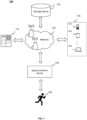
- FIG. 1 is a schematic diagram illustrating a system for monitoring user's running according to some embodiments of the present disclosure.
- a system 100 for monitoring user's running may include a processing device 110, a network 120, a storage device 130, one or more terminal devices 140, and a signal collection device 150.
- Components of the system 100 may be connected in a variety of manners.
- the signal collection device 150 may be connected to the storage device 130 and/or the processing device 110 via the network 120, or directly connected to the storage device 130 and/or the processing device 110.
- the storage device 130 may be directly connected to the processing device 110 or connected via the network 120.
- the one or more terminal devices 140 may be connected to the storage device 130 and/or the processing device 110 via the network 120 or may be directly connected to the storage device 130 and/or the processing device 110.
- the system 100 may generate running feedback information specific to a user's running status by implementing the methods and/or processes disclosed in the present disclosure.
- the processing device 110 may collect a motion signal (e.g., an EMG signal) of the leg muscles of the user when the user is running, identify a plurality of feature values of the motion signal in a plurality of target time intervals, and generate running feedback information in response to that the plurality of feature values satisfy a preset condition.
- a motion signal e.g., an EMG signal
- the processing device 110 may process data and/or information obtained from the signal collection device 150, the storage device 130, the one or more terminal devices 140, and/or other components of the system 100.
- the processing device 110 may obtain the motion signal of the user 160 from any one or more of the signal collection device 150, the storage device 130, or the one or more terminal devices 140, and process the motion signal to generate the running feedback information.
- the processing device 110 may obtain pre-stored computer instructions from the storage device 130 and execute the computer instructions to implement a method for monitoring the user's running as described herein.
- the processing device 110 may be a single server or a server group.
- the server group may be centralized or distributed.
- the processing device 110 may be local or remote.
- the processing device 110 may access information and/or data from the signal collection device 150, the storage device 130, and/or the one or more terminal devices 140 via the network 120.
- the processing device 110 may be directly connected to the signal collection device 150, the storage device 130, and/or the one or more terminal devices 140 to access the information and/or data.
- the processing device 110 may be implemented on a cloud platform.
- the cloud platform may include a private cloud, a public cloud, a hybrid cloud, a community cloud, a distributed cloud, an inter-cloud cloud, a multi-cloud, or the like, or any combination thereof.
- the network 120 may connect various components of the system 100 and/or connect the system 100 to an external resource component.
- the network 120 may enable communication between the various components of the system 100, as well as with other components of the system 100 outside of the system 100, thereby facilitating the exchange of data and/or information.
- the processing device 110 may obtain a motion signal from the signal collection device 150 and/or the storage device 130 via the network 120.
- the processing device 110 may obtain a user operation instruction from the one or more terminal devices 140 via the network 120, and exemplary operation instructions may include, but are not limited to, setting user information (e.g., gender, age, height, weight, disease history, etc.), selecting a motion mode (e.g., running, jumping rope, swimming, muscle training, etc.), setting a motion time, etc.
- setting user information e.g., gender, age, height, weight, disease history, etc.
- a motion mode e.g., running, jumping rope, swimming, muscle training, etc.
- the network 120 may be any form of wired or wireless network, or any combination thereof.
- the network 120 may include a cable network, a wired network, a fiber optic network, a telecommunication network, an intranet, the Internet, a local area network (LAN), a wide area network (WAN), a wireless local area network (WLAN), a metropolitan area network (MAN), a public switched telephone network (PSTN), a Bluetooth network, a ZigBee network, a near-field communication (NFC) network, etc. or any combination thereof.
- the network 120 may include at least one network access point, and at least one component of the system 100 may be connected to the network 120 via the access point to exchange data and/or information. For example, data such as motion signals, a user's motion status, or the like, may be communicated via the network 120.
- the storage device 130 may store data, instructions, and/or any other information.
- the storage device 130 may store data obtained from the signal collection device 150, the processing device 110, and/or the one or more terminal devices 140.
- the storage device 130 may store motion signals acquired by the signal collection device 150.
- the storage device 130 may store data and/or instructions used by the processing device 110 to execute or use to accomplish the exemplary methods described in the present disclosure.
- the storage device 130 may include mass memory, removable memory, volatile read-write memory, read-only memory (ROM), or the like, or any combination thereof.
- Exemplary mass memory may include a disk, an optical disk, a solid state disk, or the like.
- the storage device 130 may be implemented on a cloud platform.
- the cloud platform may include a private cloud, a public cloud, a hybrid cloud, a community cloud, a distributed cloud, an on-premises cloud, a multi-tiered cloud, or the like, or any combination thereof.
- the storage device 130 may be connected to the network 120 to communicate with at least one other component (e.g., the signal collection device 150, the processing device 110, the one or more terminal devices 140) of the system 100. At least one component of the system 100 may access data, instructions, or other information stored in the storage device 130 via the network 120. In some embodiments, the storage device 130 may be directly connected or in communication with one or more components (e.g., the signal collection device 150, the one or more terminal devices 140) of the system 100. In some embodiments, the storage device 130 may be part of the signal collection device 150 and/or the processing device 110.
- the one or more terminal devices 140 may receive, send and/or display data.
- Received data may include data collected by the signal collection device 150, data stored by the storage device 130, running feedback information generated by the processing device 110, etc.
- the data received and/or displayed by the one or more terminal devices 140 may include a motion signal collected by the signal collection device 150, a plurality of feature values of the motion signal in a plurality of target time intervals identified by the processing device 110, running feedback information generated by the processing device 110 based on the plurality of feature values of the motion signal, or the like.
- Sent data may include user input data, instructions, etc.
- the one or more terminal devices 140 may send the operation instruction input by the user to the signal collection device 150 via the network 120 to control the signal collection device 150 to perform data collection.
- the one or more terminal devices 140 may include a mobile device 141, a tablet computer 142, a laptop computer 143, or the like, or any combination thereof.
- the mobile device 141 may include a cell phone, a personal digital assistant (PDA), a medical mobile terminal, or the like, or any combination thereof.
- the one or more terminal devices 140 may include an input device (e.g., a keyboard, a touch screen), an output device (e.g., a display, a speaker), or the like.
- the processing device 110 may be part of the one or more terminal devices 140.
- the signal collection device 150 refers to a device that collects a motion signal from a user.
- the motion signal refers to a signal generated by the user 160 during motion.
- Exemplary motion signals may include a postural signal, an electromyographic (EMG) signal, a mechanical signal, an electrocardiographic (ECG) signal, a respiratory signal, a sweat signal, or the like.
- EMG electromyographic
- ECG electrocardiographic
- the signal collection device 150 may include a posture signal collection device, an EMG signal collection device, and a mechanics signal collection device.
- the posture signal collection device may include a velocity sensor, an inertial sensor (e.g., an acceleration sensor, an angular velocity sensor (e.g., a gyroscope), etc.), an optical sensor (e.g., an optical distance sensor, a video/image grabber), an acoustic distance sensor, a tension sensor, or the like, or any combination thereof.
- the EMG signal collection device may include one or more electrodes.
- the EMG signal collection device may include a plurality of electrodes, and the plurality of electrodes may be configured to affix with different parts (e.g., the chest, back, elbow, leg, abdomen, wrist, etc.) of the user 160 to collect EMG signals from the different parts of the user 160.
- the mechanical signal collection device may include a pressure sensor.
- pressure sensors may be provided at different parts of the user 160 so as to collect pressure signals at the different parts.
- the signal collection device 150 may also include an ECG signal collection device, a respiratory signal collection device, a sweat signal collection device, or the like.
- the ECG signal collection device may include a plurality of electrodes, and the plurality of electrodes may be configured to affix with different parts of the user 160 to collect ECG signals of the user 160.
- the respiratory signal collection device may include a respiratory frequency sensor, a flow sensor, or the like, which are respectively configured to detect signals such as a respiratory frequency, a gas flow rate, or the like, of the user 160 in motion.
- the sweat signal collection device may include a plurality of electrodes in contact with the skin of the user 160, and the plurality of electrodes may be configured to detect a flow rate of the user's sweat, analyze a composition of the sweat, or the like.
- the signal collection device 150 may have a separate power supply and may send collected data to other components (e.g., the processing device 110, the storage device 130, the one or more terminal devices 140) via wired or wireless (e.g., Bluetooth, WiFi, etc.) manners.
- one or more components of the system 100 may be implemented on the signal collection device 150.
- the processing device 110, the storage device 130, or the like may be included in the signal collection device 150. More descriptions regarding the structure of the signal collection device 150 may be found in FIG.2 , FIG.3 , FIG.4A , FIG.4 B , FIG.5 A , and FIG.5 B , and the related descriptions thereof.
- the user 160 refers to a user of the signal collection device 150.
- the user may be a runner, an exercise equipment tester, or the like.
- the user may issue a query request.
- the user inquires about his or her motion status, running feedback information, or the like.
- the user may receive feedback (e.g., a query result, running feedback information, or the like) from the signal collection device 150 or the one or more terminal devices 140.
- the count of users may be one or more.
- system 100 is intended to be exemplary and illustrative only and does not limit the scope of the present disclosure.
- various modifications and variations may be made to the system 100 under the guidance of the present disclosure. However, these modifications and variations remain within the scope of the present disclosure.
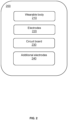
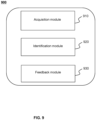
- FIG. 2 is a block diagram illustrating an exemplary signal collection device according to some embodiments of the present disclosure.
- the signal collection device 200 may be configured to collect an EMG signal of a muscle of a user.
- the signal collection device 200 may be configured to collect the EMG signal of the muscle of the user via a plurality of electrodes affixed to the skin of the user.
- the signal collection device 200 may be implemented as a wearable device (e.g., a garment), wherein a plurality of electrodes may be in contact with the skin of the user when the wearable device is worn by the user, thereby collecting the EMG signal from a surface of the skin.
- the signal collection device 200 may be in contact with a plurality of parts of the human body, such as the calf, thigh, hip, waist, back, chest, shoulder, neck, or the like, to collect EMG signals of the plurality of parts.
- the signal collection device 200 may be configured to collect an EMG signal of a leg muscle of the user.
- the signal collection device 200 may include a wearable body 210, a plurality of electrodes 220, a circuit board 230, and a plurality of additional electrodes 240.
- the wearable body 210 refers to a carrier for carrying components such as the plurality of electrodes 220, the circuit board 230, and the plurality of electrodes 220.
- the wearable body 210 may be configured as a leg-wearable device, such as a leg strap (e.g., a full leg strap, a thigh strap, a calf strap, etc.), a leg sleeve (e.g., a full leg sleeve, a thigh sleeve, a calf sleeve, etc.), a sock (e.g., a calf sock, a thigh sock, a pantyhose, etc.), a pair of pants, or the like.
- a leg strap e.g., a full leg strap, a thigh strap, a calf strap, etc.
- a leg sleeve e.g., a full leg sleeve
- the plurality of electrodes 220 may be configured to collect an EMG signal of a muscle of the user.
- the plurality of electrodes 220 may be secured to the wearable body 210 and in contact with the skin of the user to collect the EMG signal from the surface of the skin.
- the plurality of electrodes 220 may include a first electrode and a second electrode.
- the first electrode and the second electrode may be configured to collect the EMG signal of a muscle of the user.
- the muscle may refer to a single muscle or a muscle group (e.g., a quadriceps muscle group including the rectus femoris, lateral femoris, medial femoris, and intermediate femoris).
- the first electrode and the second electrode may be spaced apart along a muscle fiber direction of the muscle and extend along an extension direction perpendicular to the muscle fiber direction, respectively, so that the first electrode and the second electrode may be located at respective positions to collect potentials from the surface of the skin, and a potential difference between the collected potentials may reflect the EMG signal of the muscle.
- the plurality of electrodes 220 may further include a reference electrode, the reference electrode may be configured to provide a reference potential for the first electrode or the second electrode, thereby reducing interference from noise.
- the usability of the plurality of electrodes 220 may be improved by configuring parameters such as a material, a structure, a size, a spacing between electrodes, etc., of the first electrode and/or the second electrode.
- the size of the first electrode and/or the second electrode, and the spacing between the first electrode and the second electrode may be configured to reduce noise or an effect on the strength of the EMG signal caused by a displacement of the plurality of electrodes 220 relative to the skin, thereby achieving more accurate and more efficient signal collection.
- the performance or comfort of the signal collection device 200 may be improved by configuring the material, the structure, etc., of the plurality of electrodes 220. More descriptions regarding configuring the parameters of the plurality of electrodes may be found in FIG. 3 and the related descriptions thereof, and will not be repeated here.
- the plurality of electrodes 220 may further include one or more artifact electrodes.
- the one or more artifact electrodes may be spaced apart with respect to the first electrode and/or the second electrode along the extension direction.
- the one or more artifact electrodes may be used to eliminate noise from a signal collected by the first electrode and a signal collected by the second electrode.
- the noise may include a motion artifact noise caused by a displacement of the plurality of electrodes 220 relative to the skin, etc.
- the processing device may process the signal collected by the first electrode and the signal collected by the second electrode based on a signal collected by the one or more artifact electrodes, thereby eliminating the effect of noise on the EMG signal, and obtaining an EMG signal with higher quality. More descriptions regarding the artifact electrode may be found in FIGs. 4 A-5B and the related descriptions thereof, which will not be repeated here.
- the circuit board 230 may be secured to the wearing body 210, and the plurality of electrodes 220 may be respectively connected to the circuit board 230 by wires.
- the circuit board 230 may be provided with a processing circuit, and the processing circuit may be configured to process, store, transmit, etc., a signal.
- the processing circuit may be configured to process a signal collected by a plurality of electrodes of the circuit board 230.
- the processing device 110 in the system 100 may be implemented on the circuit board 230.
- the processing circuit may perform as the processing device 110 to implement the method for monitoring the user's running as described in the present disclosure.
- the plurality of electrodes 220 may be configured to collect EMG signals from an anterior side (i.e., a front side), a posterior side (i.e., a back side), or a medial side (i.e., an inner side) of a leg part of the user.
- an anterior side i.e., a front side
- a posterior side i.e., a back side
- a medial side i.e., an inner side
- muscles on the anterior side of the thigh of the user may include the quadriceps femoris, the sartorius, etc.; muscles on the posterior side of the thigh may include the biceps femoris, the semitendinosus, the semimembranosus, etc.; and muscles on the medial side of the thigh may include the gracilis, the adductor longus, the adductor magnus, the pectineus, etc. Since the iliotibial band on a lateral side (i.e., an outer side) of the thigh is a non-muscle tissue, it may produce little or no EMG signal.
- an effective EMG signal may not be collected, and even if an EMG signal is collected, the collected EMG signal may be susceptible to interference from adjacent anterior or posterior muscles.
- postural errors or excessive fatigue during the user's motion e.g., running, side leg raises, etc.
- the iliotibial band therefore needs to be monitored during the monitoring of the user's motion.
- the signal collection device 200 may further include a plurality of additional electrodes 220 for collecting an EMG signal of the lateral side of the thigh of the user (e.g., an EMG signal of the tensor fascia lata).
- the plurality of additional electrodes 240 may be disposed above the plurality of electrodes 220 along a height direction of the user.
- the signal collection device 200 may include one or more components (e.g., batteries, Bluetooth, amplifiers, memory, inertial sensors, etc.).
- the one or more components may be located on the lateral side of the leg or at the waist, etc., when the user is wearing the signal collection device 200.
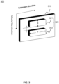
- FIG. 3 is a schematic diagram illustrating an exemplary structure of an electrode module according to some embodiments of the present disclosure.
- an electrode module 300 may include a substrate structure 310 and a plurality of electrodes 320, as shown in FIG. 3 .
- the plurality of electrodes 320 may be secured to the wearable body by the substrate structure 310.
- the substrate structure may be made of a flexible insulating material (e.g., resin, soft PVC, silicone, fabric, etc.), and the plurality of electrodes 320 may be fixedly attached to the substrate structure 310 by pasting, snap-fitting, welding, sewing, hot pressing, etc., and further fixed to the wearing body through the substrate structure 310.
- the substrate structure 310 may be omitted, and the plurality of electrodes 320 may be integrally molded (e.g., integrally woven, etc.) with the wearable body.
- the plurality of electrodes 320 may be in contact with the skin of a user when the user is wearing the signal collection device.
- the plurality of electrodes 320 may include a first electrode 321 and a second electrode 322.
- the first electrode 321 and the second electrode 322 may be configured to collect an EMG signal of a muscle of the user.
- the first electrode 321 and the second electrode 322 may be proximate to an intermediate position of the muscle in a muscle fiber direction (also referred to as a muscle length direction) when the user wears the signal collection device.
- the first electrode 321 and the second electrode 322 may be spaced apart along the muscle fiber direction and extend in an extension direction perpendicular to the muscle fiber direction, respectively. Different positions in the muscle fiber direction have different electric potentials, a position of a muscle fiber where the first electrode 321 is located has a first electric potential, a position of a muscle fiber where the second electrode 322 is located has a second electric potential, the first potential and the second potential have a potential difference between them, and the potential difference may be used to reflect the EMG signal.
- a collection accuracy and/or a collection efficiency of the plurality of electrodes 320 may be improved by configuring dimensions of the first electrode 321 and/or the second electrode 322, spacing between the first electrode 321 and the second electrode 322, or the like, to collect a signal more accurately and more efficiently.
- a width of the first electrode 321 and/or the second electrode 322 in the muscle fiber direction is a
- a length in the extension direction is b
- the spacing between the first electrode 321 and the second electrode 322 i.e., a distance between two adjacent sides of the first electrode 321 and the second electrode 322 is c.
- the length b of the first electrode 321 and/or the second electrode 322 may be determined based on the size of the muscle (also referred to as a muscle width) in the extension direction of the electrodes.
- the length b may have a large value to minimize noise caused when there is a relative displacement between the plurality of electrodes 320 and the muscle, or an effect on a strength of the collected EMG signal when the plurality of electrodes 320 are deviated from a position of the muscle.
- the length b may be greater than or equal to the width of the muscle, greater than or equal to 30% of the width of the muscle, 50% of the width, 60% of the width, 80% of the width, etc.
- the plurality of electrodes 320 may span two or more groups of muscles (e.g., a group of target muscles and a group of non-target muscles), causing collected EMG signals to interfere with each other, and further making it impossible to accurately detect the EMG signal of the target muscle. Therefore, the length b may not be too large.
- the length b may be greater than or equal to 30% of the width of the target muscle and less than or equal to a sum of the width of the target muscle and a spacing between the target muscle and the non-target muscle.
- the length b may be greater than or equal to 50% of the width of the target muscle and less than or equal to the width of the target muscle.
- a length b of an electrode 320 corresponding to the target muscle may be determined based on test data of the target muscle, and a scaling factor of the target muscle may be determined based on a relative relationship (e.g., a size relationship) of the target muscle to other target muscles of the group of target muscles, thereby determining the length b of the electrode 320 corresponding to the target muscle.
- a range of the length b of the corresponding electrode 320 may be determined based on the test data of the rectus femoris muscle.
- the length b corresponding to the rectus femoris muscle may range from 1 mm to 120 mm.
- the length b corresponding to the rectus femoris muscle may range from 10 mm to 100 mm.
- the length b corresponding to the rectus femoris muscle may range from 20 mm to 80 mm.
- different scaling factors may be determined for different target muscles.
- the size of the biceps femoris muscle is similar to the size of the rectus femoris muscle, and the scaling factor for the biceps femoris muscle may be in the range of 0.8 to 1 (e.g., 0.9).
- the length b of the electrode 320 corresponding to the biceps femoris muscle may range from 0.9 mm to 108 mm.
- the length b of the electrode 320 corresponding to the biceps femoris muscle may range from 9 mm-90 mm.
- the length b of the electrode 320 corresponding to the biceps femoris muscle may range from 18 mm-72 mm.
- the scaling factor for the tensor fasciae lata may range from 0.5 to 0.8.
- the scaling factor for the tibialis anterior may range from 0.3 to 0.7.
- the scaling factor for the gastrocnemius may range from 0.4 to 0.8.
- the strength of the EMG signal collected by the plurality of electrodes 320 may be positively correlated with the spacing c between the first electrode 321 and the second electrode 322.
- the spacing c may not be too small to avoid affecting the strength of the EMG signal.
- the spacing c may be set within a preset range.
- the spacing c may be in a range of 1 mm-50 mm.
- the spacing c may be in a range of 5 mm-40 mm.
- the spacing c may be in a range of 10 mm-30 mm.
- the width a and/or the spacing c of each electrode of the plurality of electrodes 320 may be set in a preset range.
- the end positions may be two ends (i.e., two ends of a single electrode that form the width a) of the single electrode along the muscle fiber direction.
- the width a of the single electrode needs to be within the preset range.
- the end positions may be two ends of the plurality of electrodes 320 as a whole in the muscle fiber direction (i.e., an end of the first electrode 321 and an end of the second electrode 322 away from each other).
- the width (i.e., 2a+c) of the plurality of electrodes 320 as a whole may be within a preset range.
- the preset range may be related to a target frequency (e.g., 0-500 Hz, 10 Hz -300 Hz, 30 Hz -200 Hz, 60 Hz -140 Hz, etc.) at which the cancellation needs to be avoided.
- the width a of a single electrode may be less than a half-wavelength of an EMG signal of a target frequency.
- the width 2a+c of the plurality of electrodes 320 as a whole may be less than the full wavelength of the EMG signal of the target frequency.
- the length b of the first electrode 321 or the second electrode 322 is relatively large and the width a is relatively small.
- the length b of the first electrode 321 or the second electrode 322 in the muscle fiber direction may be greater than the width a of the first electrode 321 or the second electrode 322 in the extension direction (i.e., b/a ⁇ 1).
- the performance or comfort of the signal collection device 200 may be improved by configuring a material, a structure, or the like, of the plurality of electrodes 320.
- the plurality of electrodes 320 may be waterproof, which may prevent short-circuiting between electrodes.
- the plurality of electrodes 320 may be made of a resilient material so that the signal collection device may be put on and taken off more easily, thereby improving the comfort of the signal collection device.
- an elasticity of the material of the plurality of electrodes 320 may be in a range of 0% to 200%.
- the plurality of electrodes 320 may be durable so as to withstand multiple washing machine loads, repeated wearing and taking off, skin friction, or the like without affecting other properties.
- the plurality of electrodes 320 may have a corrosion resistance (e.g., resistant to sweat corrosion).
- the plurality of electrodes 320 may have a good electrical conductivity.
- the plurality of electrodes 320 may have a conductivity greater than 10K ⁇ /cm, and a change in the conductivity of the plurality of electrodes 320 under deformation or other influences may be less than 10K ⁇ or less than 20% of an original conductivity.
- the plurality of electrodes 320 may be breathable.
- the plurality of electrodes 320 may be made of a breathable material (e.g., conductive fabric).
- the plurality of electrodes 320 may have a breathable structure (e.g., perforations, or gas channels in a middle layer).
- the plurality of electrodes 320 may have a certain degree of softness so as to ensure the comfort of the signal collection device.
- the plurality of electrodes 320 may be configured to protrude towards a surface of the skin with respect to the substrate structure 310 (or the wearing body), so that a localized pressurization effect may be achieved to promote the fit of the plurality of electrodes 320 to the surface of the skin.
- a protrusion height of the plurality of electrodes 320 may be in a range of 0-10 mm.
- a filler may be provided between the plurality of electrodes 320 and the substrate structure 310 to achieve the protrusion of the plurality of electrodes 320.
- a material of the filler e.g., a sponge, etc.
- the preset resilience and preset softness ensure that the signal collection device is comfortable when worn.
- the preset water retention capacity may reduce the accumulation of excessive water on the surface of the skin while storing part of the water to guarantee the electrodes and the skin to have good contact for a long time.
- FIG. 4A is a schematic diagram illustrating another exemplary structure of an electrode module according to some embodiments of the present disclosure.
- an electrode module 400 may include a substrate structure 410 and a plurality of electrodes 420, as shown in FIG. 4 A .
- the plurality of electrodes 420 may include a first electrode 421, a second electrode 422, and an artifact electrode 423.
- the first electrode 421 and the second electrode 422 may be the same as or similar to the first electrode 321 and the second electrode 322, respectively, as illustrated in FIG. 3 .
- the first electrodes 421 and the second electrodes 422 may be spaced apart along a muscle fiber direction and configured to collect an EMG signal of a muscle of a user.
- the EMG signal collected by the electrode module 400 may contain a motion artifacts (MA) noise.
- the MA noise is a noise caused by motion.
- the motion causes a change in the fit or position of the electrodes, increasing the noise in the collected EMG signal.
- the motion causes fluctuations in the potential of the stratum corneum, increasing the noise in the collected EMG signal.
- the artifact electrode 423 may be configured to collect a motion artifact signal, thereby removing the noise from the EMG signal.
- a potential difference between potentials collected by the first electrode 421 and the second electrode 422 without an influence of motion may be expressed as a raw EMG signal E.
- the fluctuations in the potential of the stratum corneum caused by motion may result in a motion artifact signal M1 in the signals collected by the first electrode 421 and the second electrode 422.
- the EMG signal collected by the first electrode 421 and the second electrode 422 is a composite signal of E and M1.
- the artifact electrode 423 may be spaced apart with respect to the first electrode 421 along an extension direction of the first electrode 421. In such cases, the artifact electrode 423 is located at the same potential of the muscle as the first electrode 421, and the potential difference between the artifact electrode 423 and the first electrode 421 is almost 0.
- the signal collected by the artifact electrode 423 and the first electrode 421 may be a motion artifact signal M2 due to motion.
- M2 and M1 may be motion artifact signals caused by a motion at the same moment, and thus have the same or similar characteristics (e.g., change trends, etc.). Therefore, the composite signal of E and M1 collected by the first electrode 421 and the second electrode 422 may be analyzed and processed based on M2 so as to obtain the raw EMG signal E.
- the artifact electrode 423 may be fixed relative to the first electrode 421 and/or the second electrode 422 during movement, thereby increasing a linkage between the artifact electrode 423 and the first electrode 421 and/or the second electrode 422, and avoiding an effect of a relative displacement between the artifact electrode 423 and the first electrode 421 and/or the second electrode 422 on a collection result.
- the artifact electrode 423 may be connected to the first electrode 421 and/or the second electrode 422 using a connector with a relatively small elasticity.
- the artifact electrode 423 and the first electrode 421 and/or the second electrode 422 may be provided on a substrate structure with a relatively small elasticity.
- the amplitude of the raw EMG signal directly collected by the electrodes is usually relatively small, and a processing circuit of the signal collection device may process (e.g., perform a differential amplification operation, etc. on) the amplitude of the raw EMG signal to obtain an output EMG signal.
- a processing circuit of the signal collection device may process (e.g., perform a differential amplification operation, etc. on) the amplitude of the raw EMG signal to obtain an output EMG signal.
- the value of a configuration parameter of the artifact electrode 423 may be different from the value of a configuration parameter of the first electrode 421 (or the second electrode 422) so that a difference between the signal collected by the artifact electrode 423 and the signal collected by the first electrode 421 may be increased after the differential amplification operation, thereby increasing strength of the motion artifact signal.
- the material of the artifact electrode 423 and the material of the first electrode 421 may be different.
- an area of the artifact electrode 423 and an area of the first electrode 421 may be different.
- a ratio of a difference between the area of the artifact electrode 423 and the area of the first electrode 421 to the area of the first electrode 421 may be no less than 5%.
- the pressure of the artifact electrode 423 on the skin of the user per unit area and the pressure of the first electrode 421 on the skin of the user per unit area may be different.
- a ratio of a difference between the pressure per unit area of the artifact electrode 423 and the pressure per unit area of the first electrode 421 to the pressure per unit area of the first electrode 421 may be no less than 5%.
- the artifact electrode 423 may be arranged at any position on the substrate structure 410. For example, for uneven skin surfaces, spacing the artifact electrode 423 and the first electrode 421 along the extension direction may prevent the artifact electrode 423 from fully contacting the skin surface, thereby affecting signal acquisition. Therefore, the position of the artifact electrode 423 relative to the first electrode 421 may be adjusted. As another example, the artifact electrode 423 may not be in the extension direction of the first electrode 421, so as to achieve a differentiated configuration of the positions of of the artifact electrode 423 and the first electrode 421, which may increase the strength of the motion artifact signal.
- the artifact electrode 423 may be positioned above or below the first electrode 421 in the muscle fiber direction.
- the position of the artifact electrode 423 may be further determined based on a linkage between the artifact electrode 423 and the first electrode 421 and/or the second electrode 422.
- the differentiated configuration of the positions of the artifact electrode 423 and the first electrode 421 and/or the second electrode 422 may affect the linkage between the artifact electrode 423 and the first electrode 421 and/or the second electrode 422 (e.g., a difference between M1 and M2 under a same motion is significant).
- the artifact electrode 423 may be provided at a suitable position so that M2 is as close as possible to M1 when the user performs a passive motion (i.e., the muscle does not generate EMG signals), and the position of the artifact electrode 423 at this time may be determined as a position that does not affect the linkage.
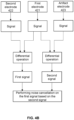
- FIG. 4B is a schematic diagram illustrating an exemplary process of noise cancellation on a signal collected by a first electrode and a signal collected by a second electrode based on a signal collected by an artifact electrode according to some embodiments of the present disclosure.
- the noise cancellation process described in FIG. 4B may be performed by a processing circuit of a signal collection device. In some embodiments, the noise cancellation process described in FIG. 4B may also be performed by other devices (e.g., the processing device 110 of the system 100). As shown in FIG. 4B , the processing circuit may obtain a first signal (i.e., a composite signal of E and M1) by performing a differential operation on a signal collected by the first electrode 421 and a signal collected by the second electrode 422, and obtain a second signal (i.e., M2) by performing a differential operation on the signal collected by the first electrode 421 and a signal collected by the artifact electrode 423. Further, the processing circuit may perform noise cancellation on the first signal based on the second signal.
- a first signal i.e., a composite signal of E and M1
- M2 i.e., M2
- the artifact electrode 423 may be the same or similar to the first electrode 421 and/or the second electrode 422.
- the artifact electrode 423 may be a third electrode configured to cooperate with other electrodes (not shown in the drawing) for collecting an EMG signal of a muscle, or the third electrode may be configured to cooperate with the first electrode 421 or the second electrode 422 for noise cancellation on the signal collected by the first electrode 421 and the signal collected by the second electrode 422.
- the noise cancellation may also be performed based on other structures and/or methods.
- a contact impedance is formed when each electrode is in contact with the skin, and the pressure, position, etc. between the electrode and the skin changes when the human body is in motion, which causes fluctuations in the contact impedance, thereby affecting accuracy of the EMG signal.
- the fluctuations in the contact impedance may be used to characterize the motion artifact signal. Therefore, the signal collection device may include a component or a processing circuit for acquiring the contact impedance, so that the noise cancellation may be achieved based on the fluctuation of the contact impedance.
- FIG. 5A is a schematic diagram illustrating another exemplary structure of an electrode module according to some embodiments of the present disclosure.
- an electrode module 500 may include a substrate structure 510 and a plurality of electrodes 520, as shown in FIG. 5A .
- the plurality of electrodes 520 may include a first electrode 521, a second electrode 522, an artifact electrode 523, and a second artifact electrode 524.
- the first electrode 521, the second electrode 522, and the artifact electrode 523 may be the same as or similar to the first electrode 421, the second electrode 422, and the artifact electrode 423, respectively, as described in FIGs. 4A and 4B .
- first electrode 521 and the second electrode 522 may be spaced apart along a muscle fiber direction and configured to collect an EMG signal of a muscle of a user.
- the artifact electrode 523 may be spaced relative to the first electrode 521 along an extension direction of the first electrode 521.
- the second artifact electrode 524 may be configured to collect an artifact signal, thereby removing noise from the EMG signal.
- the first electrode 521 and the second electrode 522 may be configured to collect an EMG signal (e.g., a composite signal of the raw EMG signal E and the artifact signal M1)
- the artifact electrode 523 and the second artifact electrode 524 may be configured to cooperate with the first electrode 521 and the second electrode 522 to collect an artifact signal, respectively.
- the artifact electrode 523 may cooperate with the first electrode 521 to determine an artifact signal M2.
- the second artifact electrode 524 may cooperate with the second electrode 522 to determine an artifact signal M2'.
- a processing circuit may analyze and process the composite signals of E and M1 based on M2 and M2' to obtain the raw EMG signal E.
- the artifact electrode 523 and the second artifact electrode 524 may be further configured to collect another EMG signal (e.g., a composite signal of a raw EMG signal E' and an artifact signal M1' at another position).
- the processing circuit may analyze and process the composite signal of E and M1 based on at least two of M2, M2', and the another EMG signal to obtain the raw EMG signal E, thereby further improving the efficiency and accuracy of the noise cancellation.
- the first electrode 521 and the second electrode 522 may be configured to collect an EMG signal of a target muscle
- the artifact electrode 523 and the second artifact electrode 524 may be configured to collect an EMG signal of a non-target muscle.
- the raw EMG signal E' at the another position has a relatively small value
- the another EMG signal may mainly include the artifact signal M1 ', so as to reduce an interference of the raw EMG signal E' in the noise cancellation process, thereby improving the efficiency and accuracy of the noise cancellation.
- FIG. 5B is a schematic diagram illustrating an exemplary process of noise cancellation on a signal collected by a first electrode and a signal collected by a second electrode based on a signal collected by an artifact electrode and a signal collected by a second artifact electrode according to some embodiments of the present disclosure.
- the processing circuit may also obtain a fourth signal (i.e., a composite signal of E' and M1') by performing a differential operation on the signal collected by the artifact electrode 523 and the signal collected by the second artifact electrode 524, and perform noise cancellation on the first signal based on at least two of the second signal, the third signal, and the fourth signal, thereby further improving the efficiency and accuracy of the noise cancellation.
- a fourth signal i.e., a composite signal of E' and M1'
- the artifact electrode 523 and the second artifact electrode 524 may be configured to collect EMG signals.
- the first electrode 521 and the second electrode 522 may be configured as a first set of electrodes to collect a first EMG signal (i.e., a composite signal of E and M1)
- the artifact electrode 523 and the second artifact electrode 524 may be configured as a second set of electrodes to collect a second EMG signal (i.e., a composite signal of E' and M1').
- the artifact electrode 523 may be configured to cooperate with the first electrode 521 to determine a first artifact signal M2, and the second artifact electrode 524 may be configured to cooperate with the second electrode 522 to determine a second artifact signal M2'.
- the processing circuit may perform the noise cancellation based on the first EMG signal, the second EMG signal, the first artifact signal, and the second artifact signal M2'.
- the plurality of signals may introduce additional reference information during analysis and processing, thereby further improving the efficiency and accuracy of the noise cancellation.
- FIG. 6 is a schematic diagram illustrating an exemplary structure of a signal collection device according to some embodiments of the present disclosure.
- a signal collection device 600 may include a wearable body 610, a first electrode module 620, a second electrode module 630, a circuit board 640, and a reference electrode 650.
- the wearable body 610 may be configured to carry the first electrode module 620, the second electrode module 630, the circuit board 640, and the reference electrode 650.
- the first electrode module 620 and the second electrode module 630 may be the same as or similar to the electrode modules (e.g., the electrode module 300, the electrode module 400, the electrode module 500) described in FIGs. 3-5A , which will not be repeated here.
- the wearable body 610 may be configured as a leg strap (e.g., a full leg strap, a thigh strap, a calf strap, etc.).
- the first electrode module 620 and the second electrode module 630 may be secured to the wearable body 610 and configured to collect EMG signals from different muscles of a leg.
- the signal collection device 600 may be worn on the thigh of a user in a strapped manner.
- two sides 611 and 612 of the wearable body 610 may include straps, interlocking Velcro, buttons, or the like, so that the wearable body 610 may be secured relative to the thigh of the user.
- the width direction (i.e., a y-direction) of the wearable body 610 may be substantially parallel to the height direction of the user.
- An upper lateral edge 613 may be located at the top (e.g., closer to the root of the thigh) of the wearable body 610, and the first electrode module 620 and the second electrode module 630 may be configured to collect EMG signals from the anterior (e.g., rectus femoris) and posterior (e.g., biceps femoris) muscles of the user's leg, respectively.
- the wearable body 610 may have a preset stretch coefficient in a length direction (i.e., x direction) of the wearable body 610 so that the wearable body 610 may be elastically stretched in the x direction to fit snugly against the skin of the thigh.
- the stretch coefficient refers to a ratio of the length of the wearable body 610 after elastic stretching to the length of the wearable body 610 in an unstretched state.
- the length of the wearable body 610 in the unstretched state may be determined based on the preset stretch coefficient and a region where the wearable body 610 is to be worn. For example, if the region where the wearable body 610 is to be worn is the thigh, with an upper dimension of 56 cm, and the preset stretch coefficient is 20%, the length of the wearable body 610 may have an upper dimension of 46 cm.
- the circuit board 640 may be secured to the wearable body 610.
- the circuit board 640 may be provided with a processing circuit, and the processing circuit may be configured to process signal and/or data, or the like.
- the processing circuit may perform differentiation, gaining, filtering, conversion, storage, transmission operations, etc., on signals collected by the electrodes.
- the signal collection device 600 may also include one or more other components (e.g., batteries, Bluetooth, memory, inertial sensors, etc.).
- the processing circuit may also process (e.g., charging, voltage stabilization, etc.) signals and/or data associated with the one or more other components.
- the wire and the electrodes connected thereto may be a one-piece structure made of the same material.
- the wire and the electrode connected thereto may be obtained by integrally cutting from a conductive film.
- the wire and the electrode connected thereto may be a one-piece structure formed by spraying a conductive material. Portions of the one-piece structure other than a skin-fitting surface of the electrode may be waterproof and insulated.
- the circuit board 640 may further include wires connected to one or more other components for processing or exchanging data, electrical energy, or the like.
- the wire may be resilient to adapt to an elastic stretching length of the wearable body 610 when worn.
- the wire may be made of an elastic material.
- a structure or a length of the wire may be configured to adapt to the elastic stretching length of the wearable body 610 when worn.
- the wire may include a first connection point connected to one electrode and a second connection point connected to the circuit board 640.
- the length of the wire may be greater than 110%, 120%, 140%, 180%, etc., of a straight-line distance between the first connection point and the second connection point, such that the wire may be adapted to a stretched length of the wearable body 610, thereby avoiding the influence of the elastic stretching of the wearable body 610 on the conductivity and structural stability when the length of the wire is too short.
- the signal collection device 600 may also include a circuit board 640 and a fixing module for one or more other components.
- the fixing module may include an elastic cloth pouch, and the elastic cloth pouch may be secured to the wearable body 610 for accommodating the circuit board 640 and the one or more other components.
- the wearable body 610 may include a two-layer structure, and the circuit board 640 and the one or more other components may be provided between the two-layer structure.
- the reference electrode 650 may be configured to provide a reference potential for the first electrode module 620 and the second electrode module 630.
- the reference electrode 650 may be provided at a location where the EMG signal is not obvious, thereby preventing the reference potential from being too large and affecting the collection of the EMG signal.
- the reference electrode 650 may be provided at an end of a muscle (e.g., a location on the thigh near the knee or the root of the thigh).
- the reference electrode 650 may be an integral electrode disposed below the wearable body 610, as shown in FIG. 6 , and the length of the integral electrode may be greater than lengths of electrodes of the first electrode module 620 and lengths of electrodes of the second electrode module 630.
- FIG. 7 is a schematic diagram illustrating another exemplary structure of a signal collection device according to some embodiments of the present disclosure.
- a signal collection device 700 may include a wearable body 710, a first electrode module 720, a second electrode module 730, a third electrode module 740, a circuit board 750, and a reference electrode 760.
- the wearable body 710, the first electrode module 720, the second electrode module 730, and the circuit board 750 may be the same or similar to the wearable body 610, the first electrode module 620, the second electrode module 630, and the circuit board 640, respectively, as shown in FIG. 6 , which are not described herein.
- the reference electrode 760 may have a split structure, as shown in FIG. 7 .
- the reference electrode 760 may include a plurality of sub-electrodes (e.g., a sub-electrode 761, a sub-electrode 762, a sub-electrode 763).
- each of the plurality of sub-electrodes may be connected to the circuit board 750 via a wire.
- the plurality of sub-electrodes may be spaced apart and connected by wires (e.g., connected in series).
- the signal collection device 700 may use other sub-electrodes as the reference electrodes when one or more of the plurality of sub-electrodes fails (e.g., falls off, short-circuits, etc.), thereby improving the stability of the signal collection device 700.
- each sub-electrode of the plurality of sub-electrodes may correspond to one electrode module.
- the sub-electrode 761 corresponds to the first electrode module 720
- the sub-electrode 762 corresponds to the second electrode module 730
- the sub-electrode 763 corresponds to the third electrode module 740.
- projections of the plurality of sub-electrodes may at least partially coincide with the first electrode module 720, the second electrode module 730, or the third electrode module 740 along a muscle fiber direction (or a y direction of the wearing body 710).
- the sub-electrode 761 and the first electrode module 720 may have the same length and position such that the projections of the sub-electrode 761 and the first electrode module 720 along the muscle fiber direction (or the y-direction) may overlap.
- the projections of the plurality of sub-electrodes at least partially coincide with the first electrode module 720, the second electrode module 730, or the third electrode module 740, a length of a region of the wearing body 710 not covered by the electrodes may be increased, thereby reducing an effect of the electrodes on elasticity of the wearing body 710, and increasing an elastic stretching length of the wearing body 710.
- the wearing body 710 may be configured as a leg strap (e.g., a full leg strap, a thigh strap, a calf strap, etc.), a leg sleeve (e.g., a full leg sleeve, a thigh sleeve, a calf sleeve, etc.), or the like.
- the first electrode module 720 and the second electrode module 730 may be configured to collect EMG signals from different muscles of the leg, respectively.
- an upper lateral edge 711 may be located at the top (e.g., closer to the root of the thigh) of the wearable body 710, and the first electrode module 720 and the second electrode module 730 may be configured to collect EMG signals from an anterior muscle (e.g., the rectus femoris) and a posterior muscle (e.g., the biceps femoris) of the user's leg, respectively.
- an anterior muscle e.g., the rectus femoris
- a posterior muscle e.g., the biceps femoris
- the iliotibial band on the lateral side of the thigh is a non-muscle tissue, it may produce little or no EMG signal.
- an effective EMG signal may not be collected, and even if an EMG signal is collected, the collected EMG signal may be susceptible to interference from adjacent anterior or posterior muscles.
- postural errors or over-fatigue during the user's motion e.g., running, side leg raises, etc.
- the iliotibial band therefore needs to be monitored during the monitoring of the user's motion.
- a condition of the iliotibial band may be determined based on an EMG signal of the tensor fascia lata.
- the third electrode module 740 may be configured as an additional electrode for collecting an EMG signal of the lateral side of the thigh of the user (e.g., the EMG signal of the tensor fascia lata).
- the third electrode module 740 may be disposed above the first electrode module 720 and the second electrode module 730 in a height direction (or y-direction) of the user.
- EMG signals may be collected at a plurality of height positions on the lateral side of the thigh of the user, and a location of the third electrode module 740 may be determined based on the strengths of the EMG signals.
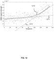
- FIG. 8 is a schematic diagram illustrating electromyographic (EMG) signals at a plurality of positions on the leg of a user according to some embodiments of the present disclosure. As shown in FIG. 8 , signals a - h are EMG signals of the leg collected at the same moment when the user performs the same action.
- the signal a is the EMG signal of an anterior thigh muscle (e.g., the rectus femoris), and b-h are the EMG signals collected at different heights on the lateral side of the thigh, with the collected positions increasing from b to h.
- the signal a may be used as a reference signal for determining the height of the third electrode module 740. For example, during side leg raises, both the rectus femoris and the vastus tensor fascia lata exert force, and thus when the rectus femoris is exerting force, the signal a may be determined as a reference signal.
- a height of that position may be designated as the height of the third electrode module 740.
- the strength of the signal g and the strength of the signal h is close to the strength of the signal a, and a position that is higher than the height corresponding to the signal g or the signal h may be determined as a position of the third electrode module 740.
- the position of the third electrode module 740 may be characterized based on the position of the first electrode module 720 or the position of the second electrode module 730.
- the third electrode module 740 is located above the first electrode module 720 and the second electrode module 730.
- a ratio of the height difference between the third electrode module 740 and the first electrode module 720 (or the second electrode module 730) to a length of the thigh may be greater than 1/10.
- the condition of the iliotibial band may be monitored based on the EMG signals of the tensor fasciae lata such that feedback information may be generated when the iliotibial band becomes fatigued, thereby preventing injury to the iliotibial band.
- the signal collection device 600 and the signal collection device 700 illustrated in FIG. 6 and FIG. 7 are only exemplary illustrations and are not limitations of the present disclosure. Based on the principles and methods of the present specification, various modifications may be made to the components of the signal collection device 600 and the signal collection device 700 to adapt to the needs of different scenarios.
- the signal collection device 600 and the signal collection device 700 may also include one or more other components.
- modifications may be made to the location, shape, size, or the like of one or more components of the signal collection device 600 and the signal collection device 700.
- the signal collection device 600 and the signal collection device 700 may also be calf straps, or be part of myoelectric pants, myoelectric suits, or the like.
- FIG. 9 is a block diagram illustrating an exemplary device for monitoring user's running according to some embodiments of the present disclosure.
- a device 900 shown in FIG. 9 for monitoring the user's running (hereinafter referred to as the device 900) may be applied to the system 100 shown in FIG. 1 , e.g., configured to the processing device 110 and/or the one or more terminal devices 140 in the form of software and/or hardware for monitoring user's running based on motion signals collected by the signal collection device 150.
- the device 900 may include an acquisition module 910, an identification module 920, and a feedback module 930.
- the acquisition module 910 may be configured to collect an EMG signal of a leg muscle of a user when the user is running.
- the leg muscle may include at least one of a calf muscle, a thigh muscle, a pelvis muscle, a hip muscle, or the like.
- the EMG signal refers to a bioelectric signal produced during muscle contractions.
- the user may use and wear a signal collection device described in some embodiments of the present disclosure (e.g., the signal collection device 150 described in FIG. 1 , the signal collection device 200 described in FIG. 2 , the signal collection device 600 described in FIG. 6 , the signal collection device 700 described in FIG.
- the acquisition module 910 may collect EMG signals directly from a signal collection device (e.g., the signal collection device 110).
- the EMG signal may be stored in a storage device (e.g., the storage device 130), and the acquisition module 910 may obtain the EMG signal from the storage device.
- the EMG signal may be used to evaluate a motion state (e.g., a running posture, a fatigue state, etc.) of the user during running.
- a motion state e.g., a running posture, a fatigue state, etc.
- Exemplary evaluations of the running posture may include evaluating the user's running skill, balance, stability, or the like during running.
- the acquisition module 910 may collect EMG signals from different leg muscles to evaluate different motion states.
- the identification module 920 may be configured to identify a plurality of feature values of the EMG signal in a plurality of target time intervals.
- a target time interval refers to a time period in a running action. In some embodiments, the target time interval may be related to a running cycle of the user.
- the plurality of feature values may be feature parameters of the EMG signal that reflect the user's motion state. Exemplary feature parameters may include amplitude values, absolute amplitude values, an average amplitude value, a maximum amplitude value, a minimum amplitude value, a medium value frequency, a peak frequency, a total force value, an EMG power, a foot contact time, an average frequency, or the like corresponding to the EMG signal in each of the plurality of target time intervals.
- the identification module 920 may be configured to identify different feature values within different target time intervals for evaluating different motion states. In some embodiments, to identify the plurality of feature values of the EMG signal in the plurality of target time intervals, the identification module 920 may be configured to segment the EMG signals based on a plurality of first time windows and determine first segmented EMG signals in the plurality of first time windows, determine a candidate value of each first segmented EMG signal, and determine, from a plurality of candidate values corresponding to the first segmented EMG signals, candidate values that satisfy a condition as the plurality of feature values.
- the duration of each first time window of the plurality of first time windows may be smaller than or equal to the running cycle of the user, and the candidate value of each first segmented EMG signal may include an average amplitude value of the each first segmented EMG signal.
- the identification module 920 may further be configured to segment the EMG signal based on a plurality of second time windows and determine second segmented EMG signals in the plurality of second time windows, and determine the plurality of feature values based on candidate values of the second segmented EMG signal in each second time window.
- the duration of each second time window may be larger than the duration of each first time window, and the feature value may be a maximum, minimum, intermediate, average, weighted average, or weighted average, etc., of the candidate values of each second segmented EMG signal.
- the candidate value of each first segmented EMG signal may include an absolute amplitude value of the first segmented EMG signal, and for each second time window, the feature value may include at least one of a maximum value, a minimum value, an intermediate value, an average value, and a weighted average value of the candidate values of the second segmented EMG signal in the second time window.
- the candidate value of each first segmented EMG signal may include an average frequency of the first segmented EMG signal, and for each second time window, the feature value may include at least one of a maximum value, a minimum value, an intermediate value, an average value, and a weighted average value of the candidate values of the second segmented EMG signal in the second time window.
- the identification module 920 may be further configured to segment the EMG signal based on a plurality of third time windows, determine third segmented EMG signals in the plurality of third time windows, and determine a feature value for each segmented EMG signal in the third time window.
- the feedback module 930 may be configured to generate running feedback information in response to that the plurality of feature values satisfy a preset condition.
- the preset condition may be a critical condition for determining the running feedback information.
- the preset condition may include a feature parameter that indicates a change in the plurality of feature values being greater than a preset threshold.
- the plurality of feature values may include a maximal value, and the preset condition may include the plurality of feature values including a feature value greater than the maximal value.
- the EMG signal may include a plurality of EMG signals corresponding to a plurality of muscles of a leg of the user
- the plurality of feature values may include amplitude ratios of EMG signals of at least two muscles of the plurality of muscles during a same running action
- the preset condition may include a difference between at least two feature values being greater than a difference threshold.
- the feedback module 930 may be configured to evaluate the user's motion state based on different preset conditions and generate running feedback information based on evaluation results.
- Exemplary running feedback information may include at least one of: a fatigue reminder, a running workout amount recommendation, a target muscle strength training recommendation, or the like.
- the running feedback information may be delivered to the user in the form of voice, text, images, etc., based on the signal collection device or a terminal device (e.g., a headset, a pair of smart glasses, a cell phone, etc.).
- a terminal device e.g., a headset, a pair of smart glasses, a cell phone, etc.
- the device 900 and its modules for monitoring user's running may be implemented in a variety of manners.
- the device and its modules may be implemented by hardware, software, or a combination of software and hardware.
- the hardware portion may be implemented utilizing dedicated logic; the software portion may be stored in memory and executed by an appropriate instruction execution system, such as a microprocessor or dedicated design hardware.
- processor control code such as provided on carrier media such as disks, CDs or DVD-ROMs, programmable memory such as read-only memories (firmware), or data carriers such as optical or electronic signal carriers.
- the device and its modules of the present disclosure may be realized not only with hardware circuits such as ultra-large scale integrated circuits or gate arrays, semiconductors such as logic chips, transistors, etc., or programmable hardware devices such as field-programmable gate arrays, programmable logic devices, etc., but also with software executed, for example, by processors of various types, or with a combination of the above hardware circuits and software (e.g., firmware).
- hardware circuits such as ultra-large scale integrated circuits or gate arrays, semiconductors such as logic chips, transistors, etc.
- programmable hardware devices such as field-programmable gate arrays, programmable logic devices, etc.
- software e.g., firmware
- the acquisition module 910, the identification module 920, and the feedback module 930 disclosed in FIG. 9 may be different modules in a system, or a single module realizing the functions of two or more modules described above.
- the individual modules may share a common storage module, and the individual modules may each have a respective storage module.
- FIG. 10 is a flowchart illustrating an exemplary process of monitoring user's running according to some embodiments of the present disclosure.
- process 1000 may be performed by processing logic that may include hardware (e.g., circuitry, specialized logic, programmable logic, microcode, etc.), software (running on a processing device to execute instructions simulated by the hardware), etc., or any combination thereof.
- one or more of the operations in the process 1000 for monitoring the user's running shown in FIG. 10 may be implemented by the processing device 110 and/or the one or more terminal devices 140 shown in FIG. 1 .
- process 1000 may be stored in the form of instructions in the storage device 130 and called and/or executed by the processing device 110 and/or the one or more terminal devices 140.
- the following takes the process 1000 performed by the processing device 110 as an example.
- process 1000 may include the following operations.
- an EMG signal of the leg muscle of a user may be obtained when the user is running.
- operation 1010 may be performed by the acquisition module 910.
- EMG signals refer to bioelectric signals produced during muscle contractions.
- the user may use or wear a signal collection device described in the present disclosure (e.g., the signal collection device 150 described in FIG. 1 , the signal collection device 200 described in FIG. 2 , the signal collection device 600 described in FIG. 6 , the signal collection device 700 described in FIG. 7 , etc.) during running to collect the EMG signal from the leg muscle.
- the processing device 110 may directly collect the EMG signal using the signal collection device (e.g., the signal collection device 110).
- the leg muscle may refer to a single muscle or a group of muscles in the leg that the user uses when running.
- the leg muscle may include a calf muscle and/or a thigh muscle.
- Exemplary calf muscles may include tibialis anterior, extensor digitorum longus, extensor hallucis longus, peroneus longus, peroneus brevis, gastrocnemius, soleus, plantaris, popliteus, flexor digitorum longus, flexor digitorum longus, tibialis posterior, or the like.
- Exemplary thigh muscles may include quadriceps femoris, sartorius, gracilis, adductor longus, adductor magnus, pectineus, biceps femoris, semitendinosus, semimembranosus, or the like.
- the movement of the legs of the user while running may also involve other parts of muscles or muscle groups associated with the legs.
- the processing device 110 may also obtain EMG signals generated by the muscles of the parts associated with the legs for running monitoring.
- the parts associated with the legs may include the pelvis, hips, or the like.
- Exemplary hip muscles may include the tensor fasciae lata, gluteus maxims, gluteus minimus, piriformis, superior gemellus, obturator internus, inferior gemellus, quadratus femoris, obturator externus, or the like; and exemplary pelvic muscles may include the iliopsoas, etc.
- the EMG signal may be used to evaluate a motion state (e.g., a running posture, a fatigue state, etc.) of the user during running.
- a motion state e.g., a running posture, a fatigue state, etc.
- Exemplary evaluation of the running posture may include evaluating the user's running skill, balance, stability, or the like during running.
- the running skill refers to whether the user's leg muscles are exerting force correctly. For example, whether the leg muscles are exerting force correctly may be determined based on a force exertion status of the user's leg muscles (e.g., whether the muscles are exerting force, an order of exertion, an intensity of exertion, etc.).
- the balance refers to the symmetry of the user's leg muscles during running, for example, whether the EMG signals of the muscles in the symmetrical parts of the left leg and the right leg are the same or similar.
- the stability refers to fluctuations in the EMG signal during different running cycles.
- the leg muscles move in a cyclical manner, wherein when the leg is in the air, some of the leg muscles (e.g., the calf muscles) are relaxed, and an amplitude of the EMG signal may be a minimum value within a cycle; and when the leg (i.e., the foot) touches the ground, some of the leg muscles tighten, and the amplitude of the EMG signal may be a maximum value within the cycle.
- the force exertion status of the leg muscles may be determined based on the amplitude of the EMG signal, thereby determining the state of the leg muscles.
- the leg muscles may also tighten when the leg is in the air due to exertion.
- whether the user's leg is in the fatigue state may be determined based on a trend of changes in the EMG signal in different running cycles.
- the EMG signal may include a plurality of EMG signals corresponding to a plurality of muscles of the user's legs.
- the user's running posture or the fatigue state may be evaluated based on a relationship (e.g., a numerical relationship, etc.) between the plurality of EMG signals.
- the processing device 110 may collect EMG signals from different leg muscles to evaluate different motion states.
- a plurality of feature values of the EMG signal in a plurality of target time intervals may be identified.
- operation 1020 may be performed by the identification module 920.
- a target time interval refers to a time period in a running action.
- the target time interval may be related to a running cycle of the user.
- the target time interval may be greater than the running cycle of the user.
- the target time interval may be less than or equal to the running cycle of the user.
- the running cycle of the user may be divided into a plurality of phases (e.g., foot contacting the ground, foot push-off, leg folding, leg swing forward, etc.), and the target time interval may correspond to one or more of the plurality of phases.
- the EMG signals may include a plurality of EMG signals corresponding to a plurality of leg muscles of the user.
- a target time interval may be the same time period corresponding to the plurality of EMG signals.
- the processing device 110 may segment the EMG signal based on a plurality of time windows and determine an average amplitude of each segmented EMG signal as a feature value of the segmented EMG signal.
- the processing device 110 may segment the EMG signal based on a plurality of first time windows and determine a candidate value of each first segmented EMG signal.
- the processing device 110 may segment the EMG signal based on a plurality of second windows and determine the plurality of feature values based on candidate values of the second segmented EMG signal in each second time window.
- the processing device 110 may directly designate a preset time period in a single running cycle as a target time interval to obtain the plurality of feature values of the EMG signal.
- the plurality of feature values refer to feature parameters in the EMG signal that characterize a motion state of the user.
- Exemplary feature parameters may include amplitude values, absolute amplitude values, an average amplitude value, a maximum amplitude value, a minimum amplitude value, a medium value frequency, a peak frequency, a total force value, an EMG power, a foot contact time, or an average frequency corresponding to the EMG signal in each of the plurality of target time intervals.
- the force exertion status of the leg muscles changes, and correspondingly, the feature parameters reflecting the user's motion state may change.
- the motion state of the user may be evaluated based on the feature parameters. For example, a total force of the leg muscles in the fatigue state is greater than a total force of the leg muscles in a non-fatigue state.
- the total force refers to a sum of amplitudes (e.g., the sum of absolute amplitude values, the sum of multiple powers of amplitudes, the sum of multiple times of amplitudes, etc.) of the EMG signal in a preset time period (e.g., a running cycle, a time period in which the foot contacts the ground, a time period in which the leg is in the air, etc.).
- an EMG power of the leg muscles in the fatigue state may be greater than an EMG power of the leg muscles in the non-fatigue state.
- the EMG power refers to a sum of amplitudes of the EMG signal per unit of time.
- the portion of the leg muscles are relaxed when the leg is in the air, and the corresponding amplitude of the EMG signal of the portion of the leg muscles may be a minimum value in a running cycle; and in the fatigue state, the portion of the leg muscles is in a tightened state when the leg is in the air, for example, the amplitude of the EMG signal of the portion of the leg muscles increases when the leg is in the air.
- a portion of the leg muscles tightens when the foot contacts the ground and the corresponding amplitude of the EMG signal may be a maximum value in a running cycle; and in the fatigue state, a muscle strength of the portion of the leg muscles abnormally increases when the foot contacts the ground, for example, the amplitude of the EMG signal increases at a speed greater than a speed threshold.
- the amplitude of the corresponding EMG signal may be greater than a preset amplitude threshold, whereby the time period in which the foot contacts the ground may be determined.
- the time period in which the foot contacts the ground in the fatigue state may be longer than the time period in which the foot contacts the ground in the non-fatigue state.
- an average frequency of the leg muscles decreases as the leg muscles move from the non-fatigue state to the fatigue state.
- the average frequency refers to a ratio of a weighted sum of the amplitude of the EMG signal at each frequency to a total sum of the amplitude of the EMG signal at the each frequency, wherein the weighted sum may include the multiplication of the amplitude at each frequency by a corresponding frequency, the multiple powers of the amplitude at each frequency, the multiple values of the amplitude at each frequency, etc.
- the plurality of target time intervals and/or the plurality of feature values corresponding to the EMG signal to be evaluated may be different for different motion states.
- the processing device 110 may identify different feature values in different target time intervals for evaluating different motion states. For example, the processing device 110 may identify the amplitudes of the EMG signals in any same time interval as the feature values when evaluating the balance of the user's running posture. As another example, in determining a fatigue state during the user's running, for each segmented EMG signal in each of plurality of time windows, the processing device 110 may identify an average amplitude of the segmented EMG signal as a feature value, wherein each time window is less than or equal to the running cycle.
- the processing device 110 may identify the amplitude of the EMG signal of a preset leg muscle (e.g., the biceps femoris) during a preset time period (e.g., a leg folding phase) in the running cycle as a feature value.
- the processing device 110 may identify a plurality of feature values in a plurality of target time intervals based on a preset motion state to be evaluated. For example, the user may select the motion state to be evaluated via a terminal device (e.g., the one or more terminal devices 140), and the processing device 110 may determine a feature value based on the motion state selected by the user.
- the processing device 110 may identify the plurality of feature values in the plurality of target time intervals based on all motion states tobe evaluated to evaluate each motion state.
- running feedback information in response to that the plurality of feature values satisfy a preset condition, running feedback information may be generated. In some embodiments, operation 1030 may be performed by the feedback module 930.
- the preset condition refers to a critical condition for determining the running feedback information.
- the processing device 110 may evaluate the user's motion state based on different preset conditions and generate running feedback information based on evaluation results.
- Exemplary running feedback information may include at least one of: a fatigue reminder, a running workout amount recommendation, a target muscle strength training recommendation, or the like.
- the running feedback information may be delivered to the user in the form of voice, text, images, etc., based on the signal collection device or a terminal device (e.g., a headset, a pair of smart glasses, a cell phone, etc.).
- the user's leg muscle gradually enters into the fatigue state.
- continuing the running action may cause an injury, such as muscle cramps, rhabdomyolysis, a joint injury, etc., since the muscles can not provide enough linking force for the joints. Therefore, whether the user's leg muscle is over-fatigued may be determined based on the preset condition and a corresponding fatigue reminder may be generated when the leg muscle is over-fatigued.
- the preset condition corresponding to over-fatigue may include a feature parameter that indicates a change in the plurality of feature values being greater than a preset threshold.
- a curve of the plurality of feature values over time may be obtained, and a slope of the curve may be designated as the feature parameter indicating the change in the plurality of feature values.
- a preset slope threshold it may be determined that the user's leg muscle is in the fatigue state.
- one or more differences between a later feature value and a prior feature value may be obtained based on a temporal order, and the differences may be designated as the feature parameters indicating the change in the plurality of feature values.
- the difference is greater than a preset difference threshold, it may be determined that the user's leg muscle is in the fatigue state.
- the plurality of feature values may include a maximal value
- the preset condition corresponding to over-fatigue may include that the plurality of feature values include a feature value greater than the maximal value.
- the preset condition corresponding to the over-fatigue may include that the plurality of feature values include a feature value greater than a reference threshold.
- the reference threshold may be determined based on historical EMG signals from historical users (e.g., the current user, users other than the current user, etc.).
- the reference threshold may be a maximum value of the plurality of feature values of the historical EMG signals.
- the reference threshold may be 90%, 80%, 70%, or the like of the maximum value of the plurality of feature values.
- a running workout amount recommendation may be generated after determining that the user is in the over-fatigue state. For example, if continuing the running for 40 minutes after the muscle is in the over-fatigue state may cause an injury, the running workout amount recommendation may be to continue running for 20 minutes, 10 minutes, or to stop immediately after the muscle enters the over-fatigue state. In some embodiments, the running workout amount recommendation may also be generated based on historical EMG signals.
- the running workout amount recommendation may be generated based on a historical running workout amount (e.g., an average or minimum of running workout amount from a plurality of historical users) corresponding to muscle over-fatigue determined from historical EMG signals.
- a historical running workout amount e.g., an average or minimum of running workout amount from a plurality of historical users
- the historical running workout amount may be combined with the current EMG signal to generate the running workout amount recommendation for the current user.
- a target muscle strength training recommendation as an example, during the running process, a plurality of leg muscles need to work together to complete the running.
- some of the plurality of leg muscles are weak, there may be insufficient muscle force, insufficient stability or balance, and easy fatigue of the muscles, which may cause problems such as difficulty in increasing the running speed, and easy injury to the muscles or other parts of the body (e.g., the knees). Therefore, based on a preset condition, whether there is a target muscle that needs to be trained may be determined and the target muscle strength training recommendation may be generated.
- the plurality of feature values may include an amplitude value (e.g., a maximum amplitude value, a minimum amplitude value, an average amplitude value, etc., during a running cycle) of the EMG signal, and the corresponding preset condition may include that the amplitude increases at a speed greater than a speed threshold.
- the amplitude of the EMG signal of a current muscle increases at a speed greater than the speed threshold, which indicates that a strength of the current muscle is abnormally increased, the current muscle may be determined as the target muscle, and the target muscle strength training recommendation may be generated.
- the plurality of feature values may include a feature value corresponding to the fatigue state, and the corresponding preset condition may include that a running workout amount (e.g., running duration or distance) when the current muscle is in a fatigue state is less than a workout amount threshold.
- a running workout amount e.g., running duration or distance
- the current muscle may be determined as the target muscle and the target muscle strength training recommendation may be generated.
- the plurality of feature values may include a feature value corresponding to the stability, and the corresponding preset condition may include that a time when a stability problem occurs is less than a preset time threshold.
- the target muscle strength training recommendation may also be generated based on a plurality of EMG signals corresponding to a plurality of leg muscles.
- the plurality of feature values may include an amplitude value of a first EMG signal of a first muscle and an amplitude value of a second EMG signal of a second muscle (e.g., the amplitude values, the absolute amplitude values, the maximum amplitude values, the minimum amplitude values, the average amplitude values, etc., of the two EMG signals at the same moment), and the corresponding preset condition may include that a ratio of the amplitude increase speeds of the two EMG signals is greater than a ratio threshold.
- the first muscle When the ratio of the amplitude increase speed of the first EMG signal to that of the second EMG signal is greater than the ratio threshold, which indicates that the strength of the first muscle is abnormally elevated relative to the strength of the second muscle, the first muscle may be determined as the target muscle, and the target muscle strength training recommendation may be generated.
- the target muscle strength training recommendation may include a target muscle recommended for training, a recommended workout amount, a training technique, etc., or any combination thereof.
- the preset condition may include one or more grades, and each grade may correspond to a different recommended workout amount and/or training technique.
- the processing device 110 may determine the grade of the preset condition satisfied by the plurality of feature values and determine the recommended workout amount and/or training technique based on the grade.
- the above process for generating the running feedback information based on the preset condition is only an exemplary illustration, and in some embodiments, other running feedback information may be generated based on other preset conditions.
- the preset condition may also include conditions related to the user's running posture (e.g., running skill, balance, stability, etc.).
- an exemplary running skill may include that the biceps femoris needs to actively exert force during the leg folding phase of a running cycle, and correspondingly, a relatively obvious EMG signal may be generated during the leg folding phase.
- an amplitude value (e.g., an absolute amplitude value) of the EMG signal of the biceps femoris muscle during the leg folding phase may be determined as a feature value, and a preset condition associated with the running skill may include that the amplitude of the EMG signal during the leg folding phase is less than a preset amplitude threshold.
- a preset condition associated with the running skill may include that the amplitude of the EMG signal during the leg folding phase is less than a preset amplitude threshold.
- the exemplary running skill may further include that the biceps femoris does not exert force during a leg swing forward phase of a running cycle, and correspondingly, the biceps femoris does not generate an obvious EMG signal during the leg swing forward phase.
- the amplitude value e.g., the absolute amplitude value
- the amplitude value of the EMG signal of the biceps femoris during the leg swing forward phase may be determined as a feature value
- a preset condition associated with the running skill may include that the amplitude value of the EMG signal during the leg swing forward phase is greater than a preset amplitude threshold.
- a preset condition related to symmetry in the running posture may include that an amplitude difference between the EMG signals of the muscles of symmetrical parts of the left leg and the right leg during the same time period is greater than a difference threshold. In response to that the amplitude difference is greater than the difference threshold, it may be determined that there is an asymmetry problem in the muscles of the symmetrical parts and corresponding running feedback information may be generated.
- a preset condition related to the stability in the running posture may include a fluctuation in the amplitude value of EMG signals of the current muscle during the same phase in different running cycles (e.g., the amplitude difference of the amplitudes in different running cycles is less than a difference threshold).
- a fluctuation in the amplitude value of the EMG signals of the current muscle during the same phase in different running cycles e.g., the amplitude difference of the amplitudes in different running cycles is less than a difference threshold.
- a preset condition related to the stability in the running posture may include a fluctuation in an amplitude ratio of EMG signals of two muscles during the same phase in different running cycles (e.g., a difference between the amplitude ratios in different running cycles is less than the difference threshold). More descriptions of identifying the plurality of feature values of the EMG signal and generating the running feedback information may be found elsewhere in the present disclosure (e.g., FIGS. 11-15 and related descriptions thereof) and will not be repeated here.
- real-time monitoring of the leg muscles during the user's running can be achieved, and timely running feedback information can be generated when an abnormal motion state is likely to occur, thereby preventing the user from getting injured during running.
- the method described in the present disclosure can also achieve comprehensive monitoring of the user's running process, which facilitates the evaluation of the motion state of the user's leg muscles during the running process, thereby generating appropriate running feedback information (e.g., the running workout amount recommendation, the target muscle strength training recommendation, etc.) based on the motion state, improving the user experience.
- process 1000 is intended to be exemplary and illustrative only, and does not limit the scope of the present disclosure.
- various modifications and variations may be made to process 1000 under the guidance of the present disclosure.
- monitoring of the user's running or other motions may be performed based on EMG signals of other parts of the body or other signals (e.g., posture signals, mechanics signals, ECG signals, respiration signals, sweat signals, etc.).
- EMG signals from the user's waist, arms, back, etc. may be obtained and combined with the EMG signals of the leg muscles for monitoring the user's running.
- running data e.g., stride frequency, stride length, speed, acceleration, explosive power, ground contact time, in air time, in air height, left-right balance, etc.
- inertial sensors may be obtained based on inertial sensors and combined with the EMG signals for monitoring the user's running.
- FIG. 11 is a flowchart illustrating an exemplary process for identifying a plurality of feature values of an EMG signal and generating running feedback information according to some embodiments of the present disclosure.
- process 1100 may be performed by processing logic that may include hardware (e.g., circuitry, specialized logic, programmable logic, microcode, etc.), software (running on a processing device to execute instructions simulated by the hardware), etc., or any combination thereof.
- processing logic may include hardware (e.g., circuitry, specialized logic, programmable logic, microcode, etc.), software (running on a processing device to execute instructions simulated by the hardware), etc., or any combination thereof.
- one or more of the operations in process 1100 shown in FIG. 11 may be performed by the processing device 110 and/or the one or more terminal devices 140 shown in FIG. 1 .
- process 1100 may be stored in the form of instructions in the storage device 130 and called and/or executed by the processing device 110 and/or the one or more terminal devices 140.
- operation 1020 and operation 1030 of process 1000 for monitoring user's running may be implemented by process 1100.
- process 1100 may be performed by the identification module 920 and the feedback module 930. The following takes the process 1100 performed by the processing device 110 as an example. As shown in FIG. 11 , process 1100 may include the following operations.
- an EMG signal may be segmented based on a plurality of first time windows and first segmented EMG signals in the plurality of first time windows may be determined.
- a candidate value of each first segmented EMG signal may be determined.
- the processing device 110 may segment the EMG signal based on a plurality of first time windows, determine first segmented EMG signals in the plurality of first time windows, and determine a candidate value of each first segmented EMG signal.
- the candidate value of each first segmented EMG signal may include one of absolute amplitude values, an average amplitude value (or average absolute amplitude value), a maximum amplitude value, a minimum amplitude value, a medium value frequency, a peak frequency, a total force value, an EMG power, a foot contact time, an average frequency, or the like, corresponding to the segmented EMG signal.
- the candidate value of each segmented EMG signal may include an average amplitude value of the segmented EMG signal.
- the processing device 110 may determine the absolute amplitude values of each segmented EMG signal, and then determine an average of the absolute amplitude values of the first segmented EMG signal in each first time window as the candidate value.
- smoothing of the EMG signal may be achieved through the plurality of first time windows, thereby reducing the redundancy of raw EMG signals and facilitating subsequent extraction of the feature values.
- the candidate value in each first time window may be used to reflect a feature of the EMG signal in the first time window.
- a magnitude of the candidate value in each first time window may reflect the magnitude of the EMG signal in the first time window, and thus reflect a force exertion status of the leg muscle in the first time window.
- the force exertion status of the leg muscles changes, and the user's motion state may be evaluated based on a change in the EMG signals during a same time period in different running cycles.
- the duration of each first time window of the plurality of first time windows is smaller than or equal to a running cycle of the user, such that a candidate value may be determined within a running cycle to reflect the feature of the EMG signal within the single running cycle.
- the duration of each first time window of the plurality of first time windows may also be determined based on a time period corresponding to the EMG signal to be evaluated.
- a difference between the duration of the first time window and the duration of the time period in which the leg is in the air may be less than a preset time difference threshold (e.g., 0.05 s, 0.03 s, 0.01 s, etc.), or a ratio of the duration of the first time window to the in air time of the leg may be within a preset ratio range (e.g., a range of 1/5-3, a range of 1/4-2, a range of 1/3-1 range, etc.), so that the determined candidate value may reflect the force exertion of the leg muscles during the in air time of the leg, which may smooth the EMG signal while retaining the feature of the EMG signal in the first time window for the evaluation of
- the first time window may be in a range of 0.01 s-0.08 s. If the user's motion state is evaluated based on the EMG signal during the in air time of the leg and the in air time of the leg is 0.05 s, the first time window may be in a range of 0.01 s-0.1 s.
- the EMG signal may be segmented based on a plurality of second time windows and second segmented EMG signals in the plurality of second time windows may be determined.
- the processing device 110 may segment the EMG signal based on a plurality of second time windows, and determine second segmented EMG signals in the plurality of second time windows.
- the duration of each second time window may be larger than the duration of each first time window such that each second segmented EMG signal may include a plurality of candidate values.
- the processing device 110 may select one or more candidate values from the plurality of candidate values in the second time window as the feature value(s) in the target time interval.
- the plurality of feature values may be determined based on the candidate values of the segmented second EMG signal in each second time window.
- the processing device 110 may determine candidate values that satisfy a condition as the plurality of feature values, thereby identifying the plurality of feature values of the EMG signal in the plurality of target time intervals.
- the processing device 110 may determine at least one of a maximum value, a minimum value, an intermediate value, an average value, and a weighted average value of the candidate values of the second segmented EMG signal in the second time window as the plurality of feature values.
- the plurality of feature values may be determined based on the plurality of second time windows by selecting feature values from a plurality of candidate values that may represent the features of the muscle during a time period (e.g., leg in the air, foot contact, etc.) of the running cycle.
- a trend of changes in leg muscles over different running cycles may be identified, which allows for monitoring the user's running based on the trend of changes in the feature values).
- a leg muscle e.g., at least one of the quadriceps femoris, sartorius, gracilis, adductor longus, adductor magnus, pectineus, biceps femoris, semitendinosus, semimembranosus, etc.
- the thigh muscles or at least one of the tibialis anterior, extensor digitorum longus, extensor hallucis longus, peroneus longus, peroneus brevis, gastrocnemius, soleus, plantaris, popliteus, flexor digitorum, flexor hallucis brevis, tibialis posterior, etc. of the calf muscles) tightens when the foot contacts the ground, and the amplitude of the corresponding EMG signal may be the maximum value in a running cycle.
- the strength of the leg muscle abnormally increases compared to that in the non-fatigued state.
- an evaluation of the motion state may be performed based on the EMG signal of the leg muscle when the foot contacts the ground.
- a maximum value of the candidate values of each second segmented EMG signal in the second time window may be selected as the plurality of feature values, which may reflect the force exertion of the leg muscle when the foot contacts the ground.
- a leg muscle e.g., at least one of the quadriceps femoris, sartorius, gracilis, adductor longus, adductor magnus, pectineus, biceps femoris, semitendinosus, semimembranosus, etc.
- the tibialis anterior, extensor digitorum longus, extensor hallucis longus, peroneus longus, peroneus brevis, gastrocnemius, soleus, plantaris, popliteus, flexor digitorum, flexor hallucis brevis, tibialis posterior, etc. of the calf muscles is relaxed when the leg is in the air, and the amplitude of the corresponding EMG signal may be the minimum within a running cycle.
- the leg muscle remains tightened when the leg is in the air. Therefore, an evaluation of the motion state may be performed based on the EMG signal of the leg muscle when the leg is in the air.
- a minimum value of the candidate values of each second segmented EMG signal in the second time window may be determined as the plurality of feature values, which may reflect the force exertion of the leg muscle when the leg is in the air.
- a median value, an average value, a weighted average value, etc., of each second segmented EMG signal within the second time window may be determined as the plurality of feature values, which may reflect an overall force exertion of the leg muscle during various phases of the running cycle.
- running feedback information in response to that the plurality of feature values satisfy a preset condition, running feedback information may be generated.
- the processing device 110 may evaluate whether the leg muscles are in an abnormal motion state based on a change in the EMG signal, and generate running feedback information when the abnormal motion state occurs. For example, in the fatigue state, the force exertion of the leg muscle changes, and when the leg muscle is overly fatigue, the force exertion changes more significantly. Therefore, in some embodiments, the preset condition may include that a feature parameter indicating a change in the plurality of feature values is greater than a preset threshold.
- the feature parameter indicating the change in the plurality of feature values may include a slope of a curve corresponding to the plurality of feature values, a difference between different feature values, or the like.
- a curve corresponding to the plurality of feature values over time may be obtained, and when the slope of the curves is greater than a preset slope threshold, which indicates that the EMG signal corresponding to the plurality of feature values changes significantly (e.g., an abnormal increase of the muscle strength when the foot contacts the ground, an abnormal tightening of the leg muscle when the leg is in the air, etc.), it may be determined that the user's leg muscle is in the over-fatigue state.
- one or more differences e.g., one or more difference values of one or more pairs of neighboring feature values, an average value of the one or more difference values, etc.
- a later feature value and a prior feature value may be obtained based on a temporal order.
- the processing device 110 may generate fatigue feedback information.
- the fatigue feedback information may be delivered to the user in the form of voice, text, images, etc., based on the signal collection device or a terminal device (e.g., a headset, a pair of smart glasses, a cell phone, etc.).
- a running workout amount recommendation may be generated after determining that the user is in the fatigue state. For example, if continuing running for 40 minutes after the muscle is in the overfatigue state may cause an injury, the running workout amount recommendation may be to continue running for 20 minutes, 10 minutes, or to stop immediately after the muscle is in the over-fatigue state. In some embodiments, the running workout amount recommendation may also be generated based on historical EMG signals.
- the running workout amount recommendation may be generated based on a historical running workout amount (e.g., an average or minimum of running workout amount of a plurality of historical users) corresponding to muscle over-fatigue determined from historical EMG signals.
- a historical running workout amount e.g., an average or minimum of running workout amount of a plurality of historical users
- the historical running workout amount may be combined with the current EMG signal to generate the running workout amount recommendations for the current user.
- FIG.12 is a schematic diagram illustrating a curve showing a change in a plurality of feature values of an EMG signal of a leg muscle of a user over time.
- the longitudinal coordinate of each coordinate point shown in FIG.12 may represent a feature value of each second segmented EMG signal in a second time window, which may reflect the amount of force generated by the leg muscle.
- the leg muscle may be the gastrocnemius muscle of the user's calf
- the longitudinal coordinate may be one of a maximum value, a minimum value, a medium value, an average value, a weighted average, etc., of the candidate values in the second time window.
- a curve 1210 is a fitting curve generated based on the plurality of feature values.
- the longitudinal coordinate increases abnormally (e.g., a slope of curve 1210 is greater than a preset slope threshold), it may indicate that the muscle exerts force abnormally due to over-fatigue.
- the curve 1210 has a relatively small slope 1211 until 100 minutes.
- the longitudinal coordinates of the coordinate points increase rapidly, and the curve 1210 has a relatively large slope 1212, indicating that the user's leg muscle exerts force abnormally after 100 minutes, and it may be determined that the leg muscle is in the over-fatigue state and fatigue feedback information may be generated.
- the feature values and the corresponding curve shown in FIG. 12 are only exemplary illustrations, and in some embodiments, when the muscle exerts force abnormally due to over-fatigue, the plurality of feature values corresponding to the EMG signal may also show other trends of changes.
- the plurality of feature values corresponding to the EMG signal may be abnormally reduced when the muscle is in the over-fatigue state, and an absolute value of a slope of a corresponding fitting curve may be greater than a preset slope threshold.
- the plurality of feature values corresponding to the EMG signal may fluctuate abnormally when the muscle is in the over-fatigue state, and the corresponding fitting curve may have a wave shape.
- process 1100 is intended to be exemplary and illustrative only and do not limit the scope of the present disclosure.
- operation 1110 may be omitted, and the processing device 110 may determine the plurality of feature values based only on the plurality of second time windows.
- the plurality of feature values may be determined from a plurality of candidate values based on other conditions.
- the plurality of feature values may be evaluated based on other preset conditions to generate the running feedback information.
- operation 1130 may be omitted, and the processing device 110 may determine the plurality of feature values based on the plurality of first time windows.
- the processing device 110 may determine a candidate value for each first segmented EMG signal based on the plurality of first time windows, based on the plurality of candidate values corresponding to the first segmented EMG signals, the second segmented EMG signals may be determined and extreme values corresponding to the second segmented EMG signals may be determined by determining extreme value points, and the extreme values may be designated as the plurality of feature values.
- FIG. 13 is a flowchart illustrating another exemplary process for identifying a plurality of feature values of an EMG signal and generating running feedback information according to some embodiments of the present disclosure.
- process 1300 may be performed by processing logic that may include hardware (e.g., circuitry, specialized logic, programmable logic, microcode, etc.), software (running on a processing device to execute instructions simulated by the hardware), etc., or any combination thereof.
- processing logic may include hardware (e.g., circuitry, specialized logic, programmable logic, microcode, etc.), software (running on a processing device to execute instructions simulated by the hardware), etc., or any combination thereof.
- one or more of the operations in the process 1300 shown in FIG. 13 may be performed by the processing device 110 and/or the one or more terminal devices 140 shown in FIG.1 .
- process 1300 may be stored in the form of instructions in the storage device 130 and called and/or executed by the processing device 110 and/or the one or more terminal devices 140.
- operations 1020 and 1030 of process 1000 for monitoring the user's running may be performed by process 1300.
- the process 1300 may be performed by the identification module 920 and the feedback module 930. The following takes the process 1300 performed by the processing device 110 as an example. As shown in FIG. 13 , process 1300 may include the following operations.
- the EMG signal may be segmented based on a plurality of third time windows, and third segmented EMG signals in the plurality of third time windows may be determined.
- a plurality of feature values may be determined by determining a feature value of each third segmented EMG signal.
- the processing device 110 may segment the EMG signal based on a plurality of third time windows, determine third segmented EMG signals in the plurality of third time windows, and determine a feature value of each third segmented EMG signal.
- the leg muscle gradually enters a fatigue state and muscle efficiency gradually decreases as a running time increases. For example, the muscle strength of the leg muscle in the fatigue state is greater than a muscle strength in a non-fatigue state when performing the same running action. As the level of fatigue increases, the muscle strength further increases. When the muscle strength is too high, the leg muscle may be injured due to over-fatigue. Therefore, the fatigue state of the leg muscle may be determined based on a change in the strength of the EMG signal.
- the fatigue state of the leg muscle may be determined based on an overall change in the strength of the EMG signal.
- each of the plurality of third time windows may be a time window of any duration.
- an average amplitude value e.g., average absolute amplitude value
- the average amplitude value may reflect the strength of each segmented EMG signal in each of the plurality of third time windows, such that the change in the strength of the EMG signal during running may be determined based on the plurality of feature values.
- running feedback information in response to that the plurality of feature values satisfy a preset condition, running feedback information may be generated.
- the processing device 110 may determine whether the leg muscle is in an abnormal motion state based on the change in the strength of the EMG signal, and generate corresponding running feedback information when the abnormal motion state occurs. For example, when the muscle strength is too high, the leg muscle may be injured due to over-fatigue. Therefore, in some embodiments, the preset condition may include that the plurality of feature values include a feature value greater than a preset feature value threshold. For example, a maximal value may be determined among the plurality of feature values. The preset condition may include that the plurality of feature values include a feature value greater than the maximal value.
- the strength of the leg muscle gradually increases to adapt to the running action and decreases after adaptation, with a maximal value of muscle strength appears during this process.
- the plurality of feature values of the EMG signal may have a maximal value.
- the leg muscle gradually enters the fatigue state and the muscle strength gradually increases.
- the muscle strength is too large (e.g., greater than the maximal value in the initial phase of running), which indicates that the muscles are overly fatigued, continuing the running action may result in an injury.
- the maximal value of the plurality of feature values may be determined, and when a feature value that is greater than the maximal value appears, it may be determined that the leg muscle is over-fatigued, and fatigue feedback information may be generated.
- the preset condition may include that the plurality of feature values include a feature value greater than a reference threshold.
- the reference threshold may be determined based on historical EMG signals of historical users (e.g., a current user, users other than the current user, etc.).
- a plurality of historical EMG signals of a plurality of historical users may be collected, a plurality of historical feature values of each historical EMG signal in a plurality of target time intervals may be identified, and a maximum historical feature value, or 90%, 80%, 70% of the maxium historical feature value may be designated as the reference threshold.
- the plurality of feature values corresponding to the EMG signal of the leg muscle of the user includes a feature value greater than the reference threshold, which indicates that the muscle strength of the user's leg muscle is relatively large and the leg muscle may be in an over-fatigue state, the fatigue feedback information may be generated.
- FIG. 14 is a schematic diagram illustrating a curve showing a change in a plurality of feature values of an EMG signal of a leg muscle of a user over time.
- the longitudinal coordinate (i.e., the feature value) of each coordinate point shown in FIG. 14 may represent an average amplitude value of candidate values in each third segmented EMG signal in a third time window, which may reflect the magnitude of the strength of the leg muscle in each third time window.
- the larger the longitudinal coordinate of each coordinate point the greater the strength of the muscle.
- a Curve 1410 is a fitting curve generated based on the plurality of feature values. As shown in FIG.
- a running process may be divided into a plurality of zones based on the change in the strength of the EMG signal indicated by the vertical coordinate. For example, in an adaptation zone, the muscle strength gradually increases to adapt to the running action, and the longitudinal coordinate of the curve 1410 enters a comfort zone after reaching a maximal value A, where the muscle strength begins to gradually decrease. As the running time increases, the leg muscle gradually becomes fatigued, and curve 1410 enters a fatigue zone, where the muscle strength gradually increases. When the muscle strength is too high (e.g., when the feature value is greater than the maximal value A), it may be determined that the leg muscle is over-fatigued, and continuing the running action may result in an injury to the muscle or joint. Therefore, a region where the feature value is greater than the I maximal value A may be determined as a warning zone, and the fatigue feedback information may be generated.
- a running workout amount recommendation may be generated after determining that the user is in an over-fatigue state. For example, as shown in Fig. 14 , curve 1410 enters the warning zone with over-fatigue at about 110 minutes and shows an injury (e.g., cramping) at about 150 minutes, at which point the running action stops and the strength of the EMG signal gradually decreases. Therefore, it may be determined that continuing the running action for 40 minutes after the over-fatigue may cause injury.
- a certain duration e.g., 1 hour, 40 minutes, 20 minutes, 5 minutes, 30 seconds, etc.
- a certain distance e.g., 5 km, 3 km, 500 m, etc.
- the running workout amount recommendation after over-fatigue of the muscle may be to continue running for no more than 40 minutes (e.g., continue running for 20 minutes, 10 minutes, or stop immediately, etc.).
- the running workout amount recommendation may be generated based on historical EMG signals.
- the running workout amount recommendation for a current user may be generated based on a historical workout amount (e.g., an average, a minimum, etc., of a plurality of historical workout amounts of a plurality of historical users) corresponding to the over-fatigue of the muscle determined based on the historical EMG signals.
- the historical workout amount may also be combined with the current EMG signal to generate the running workout amount recommendation for the current user.
- process 1300 is intended to be exemplary and illustrative only, and do not limit the scope of application of the present disclosure.
- process 1300 under the guidance of the present disclosure.
- these modifications and variations remain within the scope of the present disclosure.
- the plurality of feature values may be evaluated based on other preset conditions to generate the running feedback information.
- processes 1100 and 1300 of identifying a plurality of feature values of an EMG signal and generating running feedback information as described in FIGs. 11 and 13 are only exemplary illustrations, and in some embodiments, other running feedback information may be generated based on other preset conditions to generate other running feedback information.
- the preset condition may include conditions related to the user's running posture (e.g., running skill, balance, stability, etc.).
- the running feedback information may also include a target muscle strength training recommendation, running posture feedback information, or the like.
- FIG. 15 is a schematic diagram illustrating curves showing changes in an EMG signal of the biceps femoris muscle and an EMG signal of the rectus femoris muscle of a user over time when the user is running.
- the EMG signals in a single running cycle may be divided into four regions numbered 1-4, which correspond to four phases of the running cycle, i.e., foot contacting the ground, foot push-off, leg folding, and leg swing forward.
- an exemplary running skill may include the biceps femoris actively exerting force during the leg folding phase of a running cycle, and correspondingly a relatively obvious EMG signal may be generated during the leg folding phase.
- amplitude values e.g., absolute amplitude values
- a preset condition associated with the running skill may include that the amplitude of the EMG signal during the leg folding phase is less than a preset amplitude threshold.
- the amplitude values of the EMG signal in the leg folding phase are less than the preset amplitude threshold, it may be determined that the biceps femoris muscle is not exerting enough force in the leg folding phase, and corresponding running feedback information may be generated. For example, as shown in FIG.
- an exemplary running skill may include that the biceps femoris muscle does not exert force during the leg swing forward phase of a running cycle, and correspondingly, the biceps femoris muscle does not generate an obvious EMG signal during the leg swing forward phase.
- amplitude values (e.g., absolute amplitude values) of the EMG signal of the biceps femoris muscle during the leg swing forward phase may be directly determined as the feature values, and a preset condition associated with the running skill may include that the amplitude values of the EMG signal during the leg swing forward phase are greater than a preset amplitude threshold.
- a plurality of time intervals corresponding to the leg swing forward phase of the biceps femoris muscle may be determined as a plurality of target time intervals, and amplitude values (e.g., absolute amplitude values) of the EMG signal in the plurality of target time intervals may be determined as a plurality of feature values.
- the biceps femoris muscle may be determined to be exerting excessive force in the current phase, and corresponding feedback information may be generated.
- the EMG signal of the biceps femoris muscle shows obvious fluctuation in the leg folding phase in the 4th region, and the amplitude values of the EMG signal in the leg folding phase are greater than the preset amplitude threshold, then it may be determined that the biceps femoris muscle is exerting excessive force in the leg folding phase.
- FIG. 11 and FIG. 13 and the descriptions thereof provide methods for generating running feedback information based on the EMG signal of a single leg muscle.
- the running feedback information may be generated based on a plurality of EMG signals corresponding to a plurality of leg muscles.
- the plurality of feature values may include an amplitude ratio of EMG signals of at least two leg muscles of the plurality of leg muscles when performing the same running action
- the preset condition may include a difference between at least two feature values (i.e., amplitude ratios) in the plurality of feature values being greater than a difference threshold.
- the plurality of feature values may include an amplitude ratio (e.g., one of amplitude values, absolute amplitude values, maximum amplitude values, minimum amplitude values, average amplitude values, etc., of the two EMG signals at the same moment) of the EMG signal of the biceps femoris muscle and the EMG signal of the rectus femoris muscle when performing a same running action, and the corresponding preset condition may include that the amplitude ratio of the two EMG signals fluctuates (i.e., a difference between at least two amplitude ratios exceeding a difference threshold).
- an amplitude ratio e.g., one of amplitude values, absolute amplitude values, maximum amplitude values, minimum amplitude values, average amplitude values, etc., of the two EMG signals at the same moment
- the corresponding preset condition may include that the amplitude ratio of the two EMG signals fluctuates (i.e., a difference between at least two amplitude ratios exceeding
- the plurality of feature values may include a plurality of force exertion times of a plurality of leg muscles (e.g., times when the plurality of leg muscles generate EMG signals that are greater than a preset amplitude).
- the corresponding preset condition may include that whether a force exertion order corresponding to the plurality of force exertion times satisfies a preset force exertion order.
- the plurality of feature values may include an amplitude value of a first EMG signal of a first muscle and an amplitude value of a second EMG signal of a second muscle (e.g., one of amplitude values, absolute amplitude values, maximum amplitude values, minimum amplitude values, average amplitude values, etc., at a same moment), and the corresponding preset condition may include that a ratio of amplitude increase speeds of the two EMG signals is greater than a ratio threshold.
- the first muscle may be determined as the target muscle, and the target muscle strength training recommendation may be generated.
- the numbers expressing quantities or properties used to describe and claim certain embodiments of the present disclosure are to be understood as being modified in some instances by the term "about,” “approximate,” or “substantially.” For example, “about,” “approximate,” or “substantially” may indicate ⁇ 20% variation of the value it describes, unless otherwise stated. Accordingly, in some embodiments, the numerical parameter set forth in the written description and attached claims are approximations that may vary depending upon the desired properties sought to be obtained by a particular embodiment. In some embodiments, the numerical parameter should be construed in light of the number of reported significant digits and by applying ordinary rounding techniques. Notwithstanding that the numerical ranges and parameter setting forth the broad scope of some embodiments of the present disclosure are approximations, the numerical values set forth in the specific examples are reported as precisely as practicable.
Landscapes
- Health & Medical Sciences (AREA)
- Life Sciences & Earth Sciences (AREA)
- Engineering & Computer Science (AREA)
- Physics & Mathematics (AREA)
- General Health & Medical Sciences (AREA)
- Molecular Biology (AREA)
- Public Health (AREA)
- Veterinary Medicine (AREA)
- Animal Behavior & Ethology (AREA)
- Biophysics (AREA)
- Pathology (AREA)
- Biomedical Technology (AREA)
- Heart & Thoracic Surgery (AREA)
- Medical Informatics (AREA)
- Surgery (AREA)
- Signal Processing (AREA)
- Computer Vision & Pattern Recognition (AREA)
- Physiology (AREA)
- Artificial Intelligence (AREA)
- Psychiatry (AREA)
- Business, Economics & Management (AREA)
- Entrepreneurship & Innovation (AREA)
- Educational Administration (AREA)
- Educational Technology (AREA)
- General Physics & Mathematics (AREA)
- Theoretical Computer Science (AREA)
- Cardiology (AREA)
- Vascular Medicine (AREA)
- Physical Education & Sports Medicine (AREA)
- Measurement And Recording Of Electrical Phenomena And Electrical Characteristics Of The Living Body (AREA)
Applications Claiming Priority (1)
| Application Number | Priority Date | Filing Date | Title |
|---|---|---|---|
| PCT/CN2022/123372 WO2024065720A1 (zh) | 2022-09-30 | 2022-09-30 | 一种监控用户跑步的方法及信号采集装置 |
Publications (2)
| Publication Number | Publication Date |
|---|---|
| EP4458431A1 true EP4458431A1 (de) | 2024-11-06 |
| EP4458431A4 EP4458431A4 (de) | 2024-12-04 |
Family
ID=90475667
Family Applications (1)
| Application Number | Title | Priority Date | Filing Date |
|---|---|---|---|
| EP22960339.4A Pending EP4458431A4 (de) | 2022-09-30 | 2022-09-30 | Verfahren zur überwachung des betriebs eines benutzers und signalerfassungsvorrichtung |
Country Status (4)
| Country | Link |
|---|---|
| US (1) | US20240382138A1 (de) |
| EP (1) | EP4458431A4 (de) |
| CN (1) | CN118475389A (de) |
| WO (1) | WO2024065720A1 (de) |
Family Cites Families (9)
| Publication number | Priority date | Publication date | Assignee | Title |
|---|---|---|---|---|
| US4171696A (en) * | 1978-01-30 | 1979-10-23 | Roy John E | Prevention of distortion of brainwave data due to eye movement or other artifacts |
| US6076011A (en) * | 1999-02-02 | 2000-06-13 | J&J Engineering | Electromyographic feedback monitor system |
| US9351659B2 (en) * | 2009-07-28 | 2016-05-31 | Altec, Inc. | Biomedical electrode configuration for suppressing movement artifact |
| KR101832264B1 (ko) * | 2011-08-25 | 2018-04-13 | 삼성전자주식회사 | 생체 신호를 측정하는 장치 및 방법 |
| KR101367596B1 (ko) * | 2012-05-15 | 2014-02-26 | 주식회사 씨유메디칼시스템 | 동잡음 측정 및 제거 기능을 포함하는 심장 제세동기 |
| JP7152845B2 (ja) * | 2017-04-27 | 2022-10-13 | 株式会社 Mtg | 筋肉電気刺激装置 |
| JP7140646B2 (ja) * | 2018-11-20 | 2022-09-21 | 株式会社 Mtg | トレーニング方法 |
| CN115105819B (zh) * | 2021-03-19 | 2024-06-04 | 深圳市韶音科技有限公司 | 一种运动监控方法及其系统 |
| CN114098739A (zh) * | 2021-11-08 | 2022-03-01 | 浙江大学 | 一种用于肌电信号测量的微针阵列测量系统 |
-
2022
- 2022-09-30 WO PCT/CN2022/123372 patent/WO2024065720A1/zh not_active Ceased
- 2022-09-30 CN CN202280086643.5A patent/CN118475389A/zh active Pending
- 2022-09-30 EP EP22960339.4A patent/EP4458431A4/de active Pending
-
2024
- 2024-07-30 US US18/789,643 patent/US20240382138A1/en active Pending
Also Published As
| Publication number | Publication date |
|---|---|
| EP4458431A4 (de) | 2024-12-04 |
| CN118475389A (zh) | 2024-08-09 |
| WO2024065720A1 (zh) | 2024-04-04 |
| US20240382138A1 (en) | 2024-11-21 |
Similar Documents
| Publication | Publication Date | Title |
|---|---|---|
| CN115105100A (zh) | 运动数据处理方法和运动监控系统 | |
| US20150087925A1 (en) | Contact sensor | |
| CN115701278B (zh) | 用于肌电信号采集和处理的设备和方法 | |
| CN106923838A (zh) | 一种穿戴式坐姿检测装置、坐姿检测方法及系统 | |
| CN105581793A (zh) | 一种人体生物电监测服装 | |
| US20250057461A1 (en) | Wearable device | |
| JP2017121442A (ja) | 生体信号検出装置および生体信号検出方法 | |
| CN115485789A (zh) | 生成肌肉疲劳指示的方法、传感器及其系统 | |
| CN105748071A (zh) | 肌电采集服装及其制作方法、和用该服装进行采集的肌电采集系统 | |
| US9457185B2 (en) | Muscle supporter and muscle support method | |
| US20220008237A1 (en) | Wearable System for Evaluating Joint Performance and Function | |
| EP4458431A1 (de) | Verfahren zur überwachung des betriebs eines benutzers und signalerfassungsvorrichtung | |
| US20230096206A1 (en) | Method and Device for Diagnosing Anterior Cruciate Ligament Injury Susceptibility | |
| CN117838157A (zh) | 一种监控用户跑步的方法及信号采集装置 | |
| JP6754442B2 (ja) | ウェアラブル電極 | |
| KR101961127B1 (ko) | 신체정보 측정용 웨어러블장치 | |
| CN112336339B (zh) | 一种基于柔性传感的膝关节受力监测运动裤 | |
| CN205658909U (zh) | 肌电采集服装和用该服装进行采集的肌电采集系统 | |
| JP7701020B2 (ja) | 運動機能向上方法 | |
| US20250057476A1 (en) | Wearable devices | |
| CN207101275U (zh) | 一种基于表面肌电技术的驼背提醒装置 | |
| WO2021168109A1 (en) | Measuring muscle load in athletic activities, and associated systems and methods | |
| JP2022174772A (ja) | 衣服及び解析システム | |
| CN222533590U (zh) | 康复运动辅助护具和康复系统 | |
| RU2821773C1 (ru) | Способ обработки данных движения пользователя и система контроля движения пользователя |
Legal Events
| Date | Code | Title | Description |
|---|---|---|---|
| STAA | Information on the status of an ep patent application or granted ep patent |
Free format text: STATUS: THE INTERNATIONAL PUBLICATION HAS BEEN MADE |
|
| PUAI | Public reference made under article 153(3) epc to a published international application that has entered the european phase |
Free format text: ORIGINAL CODE: 0009012 |
|
| STAA | Information on the status of an ep patent application or granted ep patent |
Free format text: STATUS: REQUEST FOR EXAMINATION WAS MADE |
|
| 17P | Request for examination filed |
Effective date: 20240802 |
|
| AK | Designated contracting states |
Kind code of ref document: A1 Designated state(s): AL AT BE BG CH CY CZ DE DK EE ES FI FR GB GR HR HU IE IS IT LI LT LU LV MC MK MT NL NO PL PT RO RS SE SI SK SM TR |
|
| A4 | Supplementary search report drawn up and despatched |
Effective date: 20241106 |
|
| RIC1 | Information provided on ipc code assigned before grant |
Ipc: G06F 3/01 20060101ALI20241030BHEP Ipc: A61B 5/00 20060101ALI20241030BHEP Ipc: A61B 5/389 20210101ALI20241030BHEP Ipc: A61B 5/296 20210101ALI20241030BHEP Ipc: A61B 5/291 20210101ALI20241030BHEP Ipc: A61B 5/256 20210101ALI20241030BHEP Ipc: A63B 22/02 20060101AFI20241030BHEP |
|
| DAV | Request for validation of the european patent (deleted) | ||
| DAX | Request for extension of the european patent (deleted) | ||
| STAA | Information on the status of an ep patent application or granted ep patent |
Free format text: STATUS: EXAMINATION IS IN PROGRESS |
|
| 17Q | First examination report despatched |
Effective date: 20260324 |