EP4458387A1 - Drug solution administration device - Google Patents
Drug solution administration device Download PDFInfo
- Publication number
- EP4458387A1 EP4458387A1 EP23756052.9A EP23756052A EP4458387A1 EP 4458387 A1 EP4458387 A1 EP 4458387A1 EP 23756052 A EP23756052 A EP 23756052A EP 4458387 A1 EP4458387 A1 EP 4458387A1
- Authority
- EP
- European Patent Office
- Prior art keywords
- proximal
- medicinal solution
- needle cover
- casing
- distal
- Prior art date
- Legal status (The legal status is an assumption and is not a legal conclusion. Google has not performed a legal analysis and makes no representation as to the accuracy of the status listed.)
- Pending
Links
Images
















Classifications
-
- A—HUMAN NECESSITIES
- A61—MEDICAL OR VETERINARY SCIENCE; HYGIENE
- A61M—DEVICES FOR INTRODUCING MEDIA INTO, OR ONTO, THE BODY; DEVICES FOR TRANSDUCING BODY MEDIA OR FOR TAKING MEDIA FROM THE BODY; DEVICES FOR PRODUCING OR ENDING SLEEP OR STUPOR
- A61M5/00—Devices for bringing media into the body in a subcutaneous, intra-vascular or intramuscular way; Accessories therefor, e.g. filling or cleaning devices, arm-rests
- A61M5/178—Syringes
- A61M5/31—Details
- A61M5/315—Pistons; Piston-rods; Guiding, blocking or restricting the movement of the rod or piston; Appliances on the rod for facilitating dosing ; Dosing mechanisms
- A61M5/31565—Administration mechanisms, i.e. constructional features, modes of administering a dose
- A61M5/31566—Means improving security or handling thereof
- A61M5/31571—Means preventing accidental administration
-
- A—HUMAN NECESSITIES
- A61—MEDICAL OR VETERINARY SCIENCE; HYGIENE
- A61M—DEVICES FOR INTRODUCING MEDIA INTO, OR ONTO, THE BODY; DEVICES FOR TRANSDUCING BODY MEDIA OR FOR TAKING MEDIA FROM THE BODY; DEVICES FOR PRODUCING OR ENDING SLEEP OR STUPOR
- A61M5/00—Devices for bringing media into the body in a subcutaneous, intra-vascular or intramuscular way; Accessories therefor, e.g. filling or cleaning devices, arm-rests
- A61M5/178—Syringes
- A61M5/20—Automatic syringes, e.g. with automatically actuated piston rod, with automatic needle injection, filling automatically
-
- A—HUMAN NECESSITIES
- A61—MEDICAL OR VETERINARY SCIENCE; HYGIENE
- A61M—DEVICES FOR INTRODUCING MEDIA INTO, OR ONTO, THE BODY; DEVICES FOR TRANSDUCING BODY MEDIA OR FOR TAKING MEDIA FROM THE BODY; DEVICES FOR PRODUCING OR ENDING SLEEP OR STUPOR
- A61M5/00—Devices for bringing media into the body in a subcutaneous, intra-vascular or intramuscular way; Accessories therefor, e.g. filling or cleaning devices, arm-rests
- A61M5/178—Syringes
- A61M5/20—Automatic syringes, e.g. with automatically actuated piston rod, with automatic needle injection, filling automatically
- A61M5/2033—Spring-loaded one-shot injectors with or without automatic needle insertion
-
- A—HUMAN NECESSITIES
- A61—MEDICAL OR VETERINARY SCIENCE; HYGIENE
- A61M—DEVICES FOR INTRODUCING MEDIA INTO, OR ONTO, THE BODY; DEVICES FOR TRANSDUCING BODY MEDIA OR FOR TAKING MEDIA FROM THE BODY; DEVICES FOR PRODUCING OR ENDING SLEEP OR STUPOR
- A61M5/00—Devices for bringing media into the body in a subcutaneous, intra-vascular or intramuscular way; Accessories therefor, e.g. filling or cleaning devices, arm-rests
- A61M5/178—Syringes
- A61M5/31—Details
- A61M5/315—Pistons; Piston-rods; Guiding, blocking or restricting the movement of the rod or piston; Appliances on the rod for facilitating dosing ; Dosing mechanisms
- A61M5/31501—Means for blocking or restricting the movement of the rod or piston
-
- A—HUMAN NECESSITIES
- A61—MEDICAL OR VETERINARY SCIENCE; HYGIENE
- A61M—DEVICES FOR INTRODUCING MEDIA INTO, OR ONTO, THE BODY; DEVICES FOR TRANSDUCING BODY MEDIA OR FOR TAKING MEDIA FROM THE BODY; DEVICES FOR PRODUCING OR ENDING SLEEP OR STUPOR
- A61M5/00—Devices for bringing media into the body in a subcutaneous, intra-vascular or intramuscular way; Accessories therefor, e.g. filling or cleaning devices, arm-rests
- A61M5/178—Syringes
- A61M5/31—Details
- A61M5/315—Pistons; Piston-rods; Guiding, blocking or restricting the movement of the rod or piston; Appliances on the rod for facilitating dosing ; Dosing mechanisms
- A61M5/31565—Administration mechanisms, i.e. constructional features, modes of administering a dose
- A61M5/31576—Constructional features or modes of drive mechanisms for piston rods
- A61M5/31578—Constructional features or modes of drive mechanisms for piston rods based on axial translation, i.e. components directly operatively associated and axially moved with plunger rod
-
- A—HUMAN NECESSITIES
- A61—MEDICAL OR VETERINARY SCIENCE; HYGIENE
- A61M—DEVICES FOR INTRODUCING MEDIA INTO, OR ONTO, THE BODY; DEVICES FOR TRANSDUCING BODY MEDIA OR FOR TAKING MEDIA FROM THE BODY; DEVICES FOR PRODUCING OR ENDING SLEEP OR STUPOR
- A61M5/00—Devices for bringing media into the body in a subcutaneous, intra-vascular or intramuscular way; Accessories therefor, e.g. filling or cleaning devices, arm-rests
- A61M5/178—Syringes
- A61M5/31—Details
- A61M5/32—Needles; Details of needles pertaining to their connection with syringe or hub; Accessories for bringing the needle into, or holding the needle on, the body; Devices for protection of needles
-
- A—HUMAN NECESSITIES
- A61—MEDICAL OR VETERINARY SCIENCE; HYGIENE
- A61M—DEVICES FOR INTRODUCING MEDIA INTO, OR ONTO, THE BODY; DEVICES FOR TRANSDUCING BODY MEDIA OR FOR TAKING MEDIA FROM THE BODY; DEVICES FOR PRODUCING OR ENDING SLEEP OR STUPOR
- A61M5/00—Devices for bringing media into the body in a subcutaneous, intra-vascular or intramuscular way; Accessories therefor, e.g. filling or cleaning devices, arm-rests
- A61M5/178—Syringes
- A61M5/31—Details
- A61M5/32—Needles; Details of needles pertaining to their connection with syringe or hub; Accessories for bringing the needle into, or holding the needle on, the body; Devices for protection of needles
- A61M5/3202—Devices for protection of the needle before use, e.g. caps
-
- A—HUMAN NECESSITIES
- A61—MEDICAL OR VETERINARY SCIENCE; HYGIENE
- A61M—DEVICES FOR INTRODUCING MEDIA INTO, OR ONTO, THE BODY; DEVICES FOR TRANSDUCING BODY MEDIA OR FOR TAKING MEDIA FROM THE BODY; DEVICES FOR PRODUCING OR ENDING SLEEP OR STUPOR
- A61M5/00—Devices for bringing media into the body in a subcutaneous, intra-vascular or intramuscular way; Accessories therefor, e.g. filling or cleaning devices, arm-rests
- A61M5/178—Syringes
- A61M5/31—Details
- A61M5/32—Needles; Details of needles pertaining to their connection with syringe or hub; Accessories for bringing the needle into, or holding the needle on, the body; Devices for protection of needles
- A61M5/3202—Devices for protection of the needle before use, e.g. caps
- A61M5/3204—Needle cap remover, i.e. devices to dislodge protection cover from needle or needle hub, e.g. deshielding devices
-
- A—HUMAN NECESSITIES
- A61—MEDICAL OR VETERINARY SCIENCE; HYGIENE
- A61M—DEVICES FOR INTRODUCING MEDIA INTO, OR ONTO, THE BODY; DEVICES FOR TRANSDUCING BODY MEDIA OR FOR TAKING MEDIA FROM THE BODY; DEVICES FOR PRODUCING OR ENDING SLEEP OR STUPOR
- A61M5/00—Devices for bringing media into the body in a subcutaneous, intra-vascular or intramuscular way; Accessories therefor, e.g. filling or cleaning devices, arm-rests
- A61M5/178—Syringes
- A61M5/31—Details
- A61M5/32—Needles; Details of needles pertaining to their connection with syringe or hub; Accessories for bringing the needle into, or holding the needle on, the body; Devices for protection of needles
- A61M5/3205—Apparatus for removing or disposing of used needles or syringes, e.g. containers; Means for protection against accidental injuries from used needles
- A61M5/321—Means for protection against accidental injuries by used needles
- A61M5/3243—Means for protection against accidental injuries by used needles being axially-extensible, e.g. protective sleeves coaxially slidable on the syringe barrel
- A61M5/326—Fully automatic sleeve extension, i.e. in which triggering of the sleeve does not require a deliberate action by the user
-
- A—HUMAN NECESSITIES
- A61—MEDICAL OR VETERINARY SCIENCE; HYGIENE
- A61M—DEVICES FOR INTRODUCING MEDIA INTO, OR ONTO, THE BODY; DEVICES FOR TRANSDUCING BODY MEDIA OR FOR TAKING MEDIA FROM THE BODY; DEVICES FOR PRODUCING OR ENDING SLEEP OR STUPOR
- A61M5/00—Devices for bringing media into the body in a subcutaneous, intra-vascular or intramuscular way; Accessories therefor, e.g. filling or cleaning devices, arm-rests
- A61M5/178—Syringes
- A61M5/20—Automatic syringes, e.g. with automatically actuated piston rod, with automatic needle injection, filling automatically
- A61M2005/2006—Having specific accessories
- A61M2005/2013—Having specific accessories triggering of discharging means by contact of injector with patient body
-
- A—HUMAN NECESSITIES
- A61—MEDICAL OR VETERINARY SCIENCE; HYGIENE
- A61M—DEVICES FOR INTRODUCING MEDIA INTO, OR ONTO, THE BODY; DEVICES FOR TRANSDUCING BODY MEDIA OR FOR TAKING MEDIA FROM THE BODY; DEVICES FOR PRODUCING OR ENDING SLEEP OR STUPOR
- A61M5/00—Devices for bringing media into the body in a subcutaneous, intra-vascular or intramuscular way; Accessories therefor, e.g. filling or cleaning devices, arm-rests
- A61M5/178—Syringes
- A61M5/20—Automatic syringes, e.g. with automatically actuated piston rod, with automatic needle injection, filling automatically
- A61M2005/206—With automatic needle insertion
-
- A—HUMAN NECESSITIES
- A61—MEDICAL OR VETERINARY SCIENCE; HYGIENE
- A61M—DEVICES FOR INTRODUCING MEDIA INTO, OR ONTO, THE BODY; DEVICES FOR TRANSDUCING BODY MEDIA OR FOR TAKING MEDIA FROM THE BODY; DEVICES FOR PRODUCING OR ENDING SLEEP OR STUPOR
- A61M5/00—Devices for bringing media into the body in a subcutaneous, intra-vascular or intramuscular way; Accessories therefor, e.g. filling or cleaning devices, arm-rests
- A61M5/178—Syringes
- A61M5/20—Automatic syringes, e.g. with automatically actuated piston rod, with automatic needle injection, filling automatically
- A61M2005/2073—Automatic syringes, e.g. with automatically actuated piston rod, with automatic needle injection, filling automatically preventing premature release, e.g. by making use of a safety lock
- A61M2005/208—Release is possible only when device is pushed against the skin, e.g. using a trigger which is blocked or inactive when the device is not pushed against the skin
-
- A—HUMAN NECESSITIES
- A61—MEDICAL OR VETERINARY SCIENCE; HYGIENE
- A61M—DEVICES FOR INTRODUCING MEDIA INTO, OR ONTO, THE BODY; DEVICES FOR TRANSDUCING BODY MEDIA OR FOR TAKING MEDIA FROM THE BODY; DEVICES FOR PRODUCING OR ENDING SLEEP OR STUPOR
- A61M2202/00—Special media to be introduced, removed or treated
- A61M2202/0007—Special media to be introduced, removed or treated introduced into the body
-
- A—HUMAN NECESSITIES
- A61—MEDICAL OR VETERINARY SCIENCE; HYGIENE
- A61M—DEVICES FOR INTRODUCING MEDIA INTO, OR ONTO, THE BODY; DEVICES FOR TRANSDUCING BODY MEDIA OR FOR TAKING MEDIA FROM THE BODY; DEVICES FOR PRODUCING OR ENDING SLEEP OR STUPOR
- A61M2202/00—Special media to be introduced, removed or treated
- A61M2202/04—Liquids
Definitions
- the present invention relates to a medicinal solution administration device for administering a medicinal solution to a pierced living body.
- a medicinal solution administration device which is used for a subcutaneous injection to pierce the skin of a user (patient), or a target of administration, and administer a medicinal solution.
- a medicinal solution administration device disclosed in JP 6334717 B1 includes a cylindrical casing that houses a syringe main structure, a triggering member as a needle cover slidably disposed on a distal end of the casing, a cover cap detachably disposed on the distal end of the casing, and a syringe housed in the casing and filled with a medicinal solution.
- the triggering member In a case where the medicinal solution administration device is accidentally dropped on the floor or the like from the cover cap side before the medicinal solution is administered by the medicinal solution administration device, the triggering member is pushed up in a direction away from the distal end due to an impact applied to the cover cap. In this instance, an arm of the triggering member comes into contact with a stopper of the casing and restricts the movement of the triggering member toward the proximal side. This configuration prevents erroneous actuation of a drive unit that drives a gasket (piston) inside the syringe in a distal direction.
- the movement of the triggering member toward the proximal end is restricted by the stopper but the drive unit for driving the gasket is not restricted at all. For this reason, when the medicinal solution administration device is accidentally dropped on the floor or the like from the cover cap side, it is conceivable that a part of the drive unit moves inside the casing due to an inertial force and that the drive unit is actuated and pushes the piston (the drive unit actuates erroneously).
- An object of the present invention is to solve the problem.
- An aspect of the present invention includes:
- the movement restricting mechanism prevents the movement of the needle cover in the proximal direction relative to the cap, and when an inertial force acts on the drive unit, the coupling mechanism is involved to prevent the drive unit from moving in the proximal direction relative to the needle cover.
- a medicinal solution administration device 10 is used, for example, for administering a medicinal solution M subcutaneously to a patient, or a user.
- the medicinal solution administration device 10 includes a casing 12 formed into a hollow cylindrical shape, a needle cover 14 movably housed in the casing 12, a syringe 16 housed in the needle cover 14, a cap 18 detachably disposed on a distal end of the casing 12, and a coupling mechanism 19 that couples the needle cover 14 and a sliding member 64 to be described.
- the casing 12 is formed of a resin material and has a circular cross section.
- the casing 12 includes a cylinder 20 having an outside diameter and an inside diameter substantially constant along the axial direction (directions of arrows A and B), a sleeve body 22 housed in the cylinder 20 on the proximal side (direction of arrow A), and an end cap 24 that closes a proximal end of the cylinder 20.
- the cylinder 20 has a predetermined length in the axial direction (directions of arrows A and B).
- the cylinder 20 has an opened distal end and opened proximal end.
- the cylinder 20 has the peripheral wall provided with a viewing window 26.
- the viewing window 26 penetrates the peripheral wall of the cylinder 20 and is opened at a position corresponding to a position of a barrel 124 of the syringe 16 housed in the cylinder 20.
- the medicinal solution M in the barrel 124 can be checked through the viewing window 26.
- a pair of recesses 28 is formed on the distal end of the cylinder 20 (see Fig. 4 ).
- the recesses 28 have a rectangular cross section and are depressed radially with respect to the inner periphery of the cylinder 20.
- the pair of recesses 28 is symmetric about the axis of the cylinder 20 on the outer periphery of the cylinder 20.
- the sleeve body 22 is formed into a hollow shape.
- the sleeve body 22 includes a body main structure 30 formed into a cylindrical shape and an enlarged diameter portion 32 formed on the proximal side of the body main structure 30 (direction of arrow A).
- the body main structure 30 has a substantially constant diameter along the axial direction (directions of arrows A and B).
- the body main structure 30 has the inner periphery provided with four guiding ribs 34 protruding radially inward.
- the guiding ribs 34 are separated from each other at 90-degree intervals along the circumferential direction of the body main structure 30.
- the number of guiding ribs 34 is not limited to four.
- the guiding ribs 34 have a substantially constant thickness, protruding linearly and radially inward from the inner periphery of the body main structure 30.
- the guiding ribs 34 have the same radially protruding length.
- the guiding ribs 34 face each other in pairs across the central axis of the body main structure 30.
- the sleeve body 22 houses a locking pin 44 and a plunger 82 to be described in a movable manner in the axial direction.
- a boundary between the enlarged diameter portion 32 and the body main structure 30 is provided with a plurality of protrusions 38 protruding radially inward.
- the protrusions 38 have a rectangular cross section and protrude radially outward from the inner periphery of the body main structure 30. Proximal ends of the protrusions 38 are bevels that are inclined gradually and radially inward (see Fig. 7 ).
- the protrusions 38 are engaged with brims 96 of flexible portions 86 in the plunger 82 to be described on the proximal side (direction of arrow A).
- the number and arrangement of the protrusions 38 correspond to the number and arrangement of the flexible portions 86.
- the sleeve body 22 is housed in the cylinder 20 from the proximal end of the cylinder 20, and the enlarged diameter portion 32 is engaged with an inner peripheral portion of the cylinder 20. Accordingly, a proximal end of the enlarged diameter portion 32 is housed and fixed at a position closer to the distal side (direction of arrow B) than the proximal end of the cylinder 20 by a predetermined distance.
- the body main structure 30 has the outer periphery provided with a pair of locking grooves 40 that is depressed radially inward.
- the pair of locking grooves 40 is symmetric about the central axis of the sleeve body 22, and the locking grooves 40 are engaged with locking claws 62 of the locking pin 44 to be described.
- a sleeve spring 42 is disposed between the outer periphery of the body main structure 30 and the inner periphery of the cylinder 20.
- the sleeve spring 42 is an elastic member composed of a coil spring.
- a proximal end of the sleeve spring 42 is engaged with a distal end of the enlarged diameter portion 32.
- a distal end of the sleeve spring 42 is engaged with the sliding member 64 to be described.
- An elastic force of the sleeve spring 42 biases the sliding member 64 in a direction away from the sleeve body 22, that is, in the distal direction (direction of arrow B).
- the sleeve body 22 houses the locking pin 44 that straddles the enlarged diameter portion 32 and the body main structure 30.
- the locking pin 44 is movable in the axial direction (directions of arrows A and B) inside the sleeve body 22.
- the locking pin 44 includes a cylindrical pin main structure 46 formed at the center and a pair of arms 48 disposed on the outer periphery of the pin main structure 46.
- the arms 48 are connected to a proximal end of the pin main structure 46 in an integrated manner.
- the pin main structure 46 includes a flat end wall 50 formed on the proximal end and perpendicular to the axial direction, a large diameter portion 52 extending from the center of the end wall 50 toward the distal side (direction of arrow B), and a small diameter portion 54 formed on the distal side of the large diameter portion 52 (direction of arrow B) with a diameter smaller than that of the large diameter portion 52.
- the pin main structure 46 has a hole 56 on the central axis. The hole 56 extends along the axial direction with a constant diameter, linearly penetrating the end wall 50, the large diameter portion 52, and the small diameter portion 54. Into the hole 56, a shaft 78 of the end cap 24 and an injection spring 58 to be described are inserted.
- Proximal ends of the arms 48 are connected to the end wall 50 of the pin main structure 46 and are arranged in parallel at a predetermined interval on the outer periphery of the pin main structure 46.
- the arms 48 have the same length, extending toward the distal end (direction of arrow B).
- Distal ends of the arms 48 have engaging ends 60 engaged with the sliding member 64 to be described and the locking claws 62 formed on the radially inner side of the engaging ends 60.
- the engaging ends 60 have a flat shape perpendicular to a direction of extension of the arms 48.
- the locking claws 62 protrude radially inward from the engaging ends 60 and toward the distal side (direction of arrow B).
- the locking claws 62 have a triangular cross-sectional shape tapered toward the distal ends of the arms 48.
- protrusive portions 48a Centers of the arms 48 in the longitudinal direction are provided with protrusive portions 48a that protrude outward.
- the protrusive portions 48a protrude outward from outer surfaces of the arms 48 and have a rectangular shape elongated in a direction perpendicular to the direction of extension of the arms 48.
- the protrusive portions 48a are inserted into slits 641 of the sliding member 64 to be described.
- the cylindrical sliding member 64 is disposed on the distal side (direction of arrow B) of the locking pin 44.
- the sliding member 64 is movable in the axial direction (directions of arrows A and B) inside the cylinder 20.
- the plunger 82 and the body main structure 30 of the sleeve body 22 are inserted into the sliding member 64.
- the sliding member 64 includes a cylindrical sleeve main structure 64a, a cylindrical portion 64b disposed on a distal end of the sleeve main structure 64a, and a pair of engaging arms 64c extending from a proximal end of the sleeve main structure 64a.
- the cylindrical portion 64b increases in diameter as compared with the sleeve main structure 64a. That is, the diameter of the cylindrical portion 64b is larger than that of the sleeve main structure 64a.
- a boundary between the sleeve main structure 64a and the cylindrical portion 64b has a stepped catcher 65. As illustrated in Fig. 8 , the catcher 65 retains the distal end of the sleeve spring 42 disposed on the outer periphery of the sliding member 64. An elastic force of the sleeve spring 42 biases the sliding member 64 toward the distal end.
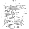
- the cylindrical portion 64b has first connections 66 as part of the coupling mechanism 19.
- the first connections 66 are disposed in pairs, being apart from each other along the circumferential direction of the cylindrical portion 64b.
- the first connections 66 are symmetric about the axis of the sliding member 64.
- Each first connection 66 has a housing recess 66a and first and second flexible arm portions 67a and 67b disposed in the housing recess 66a.
- Each housing recess 66a is depressed radially inward from the outer periphery of the cylindrical portion 64b and is open from a distal end of the cylindrical portion 64b toward a proximal end.
- each housing recess 66a has a trapezoidal shape narrowed toward a proximal end of the sliding member 64.
- side walls 661 and 662 constituting both sides of each housing recess 66a in the circumferential direction of the cylindrical portion 64b are inclined inward from the distal end toward the proximal end.
- the first and second flexible arm portions 67a and 67b are separated from each other along the circumferential direction of the cylindrical portion 64b and are respectively arranged along the inclined side walls 661 and 662 of each housing recess 66a.
- the first flexible arm portion 67a and the second flexible arm portion 67b are symmetrical about the center of each housing recess 66a.
- the first and second flexible arm portions 67a and 67b are in parallel to the side walls 661 and 662 of each housing recess 66a while being separated from the side walls 661 and 662.
- One ends (ends in the direction of arrow B) of the first and second flexible arm portions 67a and 67b are fixed ends 671 and 672 and are connected to the distal end of the cylindrical portion 64b.
- the first and second flexible arm portions 67a and 67b are inclined at an angle 8, having the fixed ends 671 and 672 of the first and second flexible arm portions 67a and 67b functioning as bases.
- the angle ⁇ is, for example, in the range of 5 to 45 degrees.
- the other ends (end in the direction of arrow A) of the first and second flexible arm portions 67a and 67b are free ends 673 and 674 and are not connected to the cylindrical portion 64b.
- the fixed ends 671 and 672 of the first and second flexible arm portions 67a and 67b are closer to the distal end of the cylindrical portion 64b than the free ends 673 and 674.
- the first and second flexible arm portions 67a and 67b have a tiltable cantilever structure with the fixed ends 671 and 672 functioning as bases.
- the first and second flexible arm portions 67a and 67b are elastically deformable.
- a length E from the fixed ends 671 and 672 to the free ends 673 and 674 of the first and second flexible arm portions 67a and 67b is, for example, 3 mm or more along a direction of extension of the first and second flexible arm portions 67a and 67b.
- the first flexible arm portion 67a and the second flexible arm portion 67b have the same length.
- Each housing recess 66a has a space between the first flexible arm portion 67a and the second flexible arm portion 67b. Each space houses a second connection 123 of the needle cover 14, that is, part of the coupling mechanism 19.
- the pair of engaging arms 64c is symmetric about the axis of the sliding member 64, and each engaging arm 64c protrudes in the proximal direction of the sliding member 64.
- the engaging arms 64c have the slits 641.
- the slits 641 have a rectangular shape along a direction of extension of the engaging arms 64c.
- Proximal ends of the slits 641 have protruding pieces 642 protruding from proximal ends of the engaging arms 64c toward distal ends.
- the protruding pieces 642 are inclined inward toward the distal ends.
- each arm 48 of the locking pin 44 is inserted into each slit 641.
- the engaging ends 60 of the locking pin 44 can be engaged with distal ends of the slits 641.
- the protrusive portions 48a of the arms 48 can be engaged with the protruding pieces 642. Accordingly, the locking pin 44 is engaged with the sliding member 64, and the locking pin 44 is prevented from being detached from the sliding member 64 in the proximal direction.
- an end guide 68 is disposed to face a distal end of the sliding member 64.
- the end guide 68 has a cylindrical shape having a diameter substantially equal to that of the sliding member 64.
- the plunger 82 is inserted into the end guide 68 in a movable manner in the axial direction.
- guiding grooves 70 for rotating the plunger 82 are disposed on the inner periphery of the end guide 68.
- the guiding grooves 70 are depressed radially outward with respect to the inner periphery of the end guide 68.
- the brims 96 of the flexible portions 86 of the plunger 82 to be described are inserted into the guiding grooves 70.
- the guiding grooves 70 are arranged at four places at equal intervals in the circumferential direction, corresponding to the number and arrangement of the flexible portions 86.
- each guiding groove 70 includes an inclined guiding portion 72 and a linear guiding portion 74.
- the inclined guiding portions 72 are inclined in the distal direction (direction of arrow B) with respect to the axial direction (directions of arrows A and B) of the end guide 68.
- the linear guiding portions 74 extend in a straight line from distal ends of the inclined guiding portions 72.
- a width along the circumferential direction of the linear guiding portions 74 is substantially equal to or slightly larger than a width of the brims 96 of the plunger 82 to be described.
- the end cap 24 has a lid 76 that closes the proximal end of the cylinder 20 and the shaft 78 extending from the center of the lid 76 toward the distal side (direction of arrow B).
- the lid 76 has a disk-like shape having the same diameter as the outside diameter of the cylinder 20.
- the lid 76 has a pusher 80 protruding from an end face on the distal side.
- the pusher 80 is formed into an annular shape protruding from the end face of the lid 76.
- the shaft 78 is a shaft body extending toward the distal side (direction of arrow B) along the axial direction.
- the shaft 78 is housed in the cylinder 20 and the sleeve body 22, extending to a part near the center of the cylinder 20 in the axial direction.
- the injection spring 58 and the plunger 82 are allowed to pass through the outer periphery of the shaft 78.
- the injection spring 58 is a coil spring, having an elongated shape corresponding to the axial length of the shaft 78.
- the injection spring 58 is interposed between the plunger 82 to be described and the end face of the lid 76, and an elastic force of the injection spring 58 biases the plunger 82 in the distal direction (direction of arrow B).
- the opened proximal end is closed by the lid 76 and the shaft 78 is disposed on the axis of the cylinder 20.
- the plunger 82 has a cylindrical shape elongated in the axial direction (directions of arrows A and B).
- the plunger 82 includes a rod main structure 84 having a constant diameter along the axial direction, a plurality of flexible portions 86 formed on the proximal side (direction of arrow A) of the rod main structure 84 and divided in the circumferential direction, and an attaching portion 90 formed on the distal side (direction of arrow B) of the rod main structure 84 and to which a top 88 to be described is attached.
- the rod main structure 84 has a circular cross section. As illustrated in Fig. 2 , the rod main structure 84 has the outer periphery provided with four sliding grooves 92 that are depressed radially inward. The sliding grooves 92 have a rectangular cross section and are depressed with respect to the outer periphery of the rod main structure 84. As illustrated in Fig. 5 , the guiding ribs 34 of the sleeve body 22 are inserted into the sliding grooves 92. The sliding grooves 92 are separated at equal intervals in the circumferential direction, corresponding to the number and arrangement of the guiding ribs 34. The sliding grooves 92 correspond to the four guiding ribs 34.
- the inside of the rod main structure 84 has a first rod hole 94 extending along the axial direction (directions of arrows A and B). Into this first rod hole 94, the shaft 78 of the end cap 24 and the injection spring 58 are inserted.
- the flexible portions 86 protrude in the axial direction (direction of arrow A) from a proximal end of the rod main structure 84 and are separated from each other in the circumferential direction. Each flexible portion 86 is disposed between two adjacent sliding grooves 92.
- the distal side (direction of arrow B) of the flexible portions 86 connected to the rod main structure 84 functions as a fulcrum, and the proximal side (direction of arrow A) of the flexible portions 86 is radially tiltable.
- proximal ends of the flexible portions 86 are provided with the brims 96 protruding radially outward. Surfaces of the brims 96 on the distal side (direction of arrow B) are bevels that are inclined gradually and radially outward toward the proximal side.
- the flexible portions 86 have a diameter increasing radially outward from the rod main structure 84.
- the small diameter portion 54 of the locking pin 44 is inserted into the interior of the flexible portions 86.
- the inner peripheral diameter of the flexible portions 86 is larger than that of the first rod hole 94.
- the brims 96 of the flexible portions 86 have an outside diameter D1 slightly larger than an inside diameter D2 of the body main structure 30 of the sleeve body 22 (D1 > D2).
- the attaching portion 90 has a small diameter with respect to the rod main structure 84.
- the outer periphery of the attaching portion 90 is provided with a pair of engaging chips 98 protruding radially outward.
- the pair of engaging chips 98 is engaged with the top 88 to be described.
- the engaging chips 98 extend in the horizontal direction perpendicular to the axial direction of the plunger 82, being symmetric about the central axis of the plunger 82.
- the attaching portion 90 includes a second rod hole 100 extending along the axial direction (directions of arrows A and B).
- the second rod hole 100 is smaller in diameter than the first rod hole 94, and the shaft 78 of the end cap 24 is inserted through the second rod hole 100.
- a distal end of the injection spring 58 is engaged with a stepped portion formed at a boundary between the second rod hole 100 and the first rod hole 94. Accordingly, an elastic force of the injection spring 58 biases the plunger 82 in a direction away from the end cap 24, that is, in the distal direction (direction of arrow B) .
- the top 88 has a cup-like shape with the proximal side (direction of arrow A) opened.
- the top 88 is rotatable relative to the attaching portion 90 of the plunger 82.
- the top 88 includes a cylindrical cup portion 102 disposed on the proximal side and a mounting portion 104 protruding from a distal end of the cup portion 102.
- a gasket 106 formed of an elastic material is attached to the top 88 so as to cover the outer periphery of the mounting portion 104.
- the attaching portion 90 of the plunger 82 is inserted into the cup portion 102 from the proximal side.
- the outer periphery of the cup portion 102 is provided with a pair of introducing grooves 108 which penetrates the cup portion 102 radially and through which the engaging chips 98 of the plunger 82 are inserted.
- the introducing grooves 108 are arranged in pairs, being symmetric about the central axis of the cup portion 102.
- Each introducing groove 108 includes a horizontal portion 110 formed near a proximal end of the cup portion 102 and extending along the circumferential direction and a perpendicular portion 112 perpendicular to the horizontal portion 110 and extending from one end in the circumferential direction toward the distal side (direction of arrow B).
- Each introducing groove 108 substantially has a L-shape including the horizontal portion 110 and the perpendicular portion 112.
- Each connecting portion between the horizontal portion 110 and the perpendicular portion 112 has an inclined portion 114 inclined at a predetermined angle.
- the attaching portion 90 of the plunger 82 is inserted into the cup portion 102, and the engaging chips 98 are inserted into the pair of introducing grooves 108. Accordingly, the top 88 and the plunger 82 are connected in the axial direction and movable along the axial direction in an integrated manner. After the gasket 106 is attached to the mounting portion 104 of the top 88, the gasket 106 is inserted into the barrel 124 of the syringe 16 to be described.
- the needle cover 14 is movably disposed inside the cylinder 20 constituting the casing 12.
- the needle cover 14 includes a cylindrical main structure 116, a pair of covering portions 118 extending from the main structure 116 toward the proximal side (direction of arrow A), and a pair of extending portions 119 extending from proximal ends of the covering portions 118.
- the main structure 116 is disposed on the distal side (direction of arrow B) of the needle cover 14, and the center of the main structure 116 is opened by a hole 14a penetrating the main structure 116 in the axial direction.
- the covering portions 118 are symmetric about the axis of the needle cover 14, extending along the axial direction.
- the main structure 116 includes a pair of engaging holes 120 with which the retaining arms 148 of the cap 18 are engaged.
- the covering portions 118 include syringe guiding holes 122 elongated along the axial direction.
- the syringe guiding holes 122 and the engaging holes 120 are linearly arranged along the axial direction of the needle cover 14.
- the syringe guiding holes 122 and the engaging holes 120 are separated from each other by a predetermined distance in the axial direction of the needle cover 14.
- the engaging holes 120 radially penetrate the main structure 116.
- the engaging holes 120 have a rectangular shape elongated in a direction perpendicular to the axial direction of the needle cover 14.
- the syringe guiding holes 122 radially penetrate the covering portions 118.
- a syringe holder 130 to be described is engaged with the syringe guiding holes 122 in a movable manner in the axial direction.
- the syringe guiding holes 122 have a function of introducing the syringe holder 130 in the axial direction.
- each extending portion 119 includes a pair of ribs 119a.
- the ribs 119a are disposed on both ends of each extending portion 119 in the width direction, extending along each extending portion 119.
- the ribs 119a protrude from the inner surface of each extending portion 119.
- Proximal ends 119b of the ribs 119a are disposed near the proximal end of each extending portion 119.
- the second connections 123 are part of the coupling mechanism 19. As shown in Fig. 12 , the second connections 123 can be coupled to the first connections 66 of the sliding member 64.
- the coupling mechanism 19 has the first and second connections 66 and 123, being capable of coupling the distal end of the sliding member 64 and a proximal end of the needle cover 14.
- the second connections 123 each include an extending end 123a gradually narrowing with respect to each extending portion 119, a projection 123b disposed on a proximal end of the extending end 123a, and jaws 123c disposed on a connecting portion between the extending end 123a and the projection 123b.
- the extending end 123a is inclined, gradually narrowing from the proximal end of each extending portion 119 toward the proximal direction (direction of arrow A). Side portions of the extending end 123a in the width direction are inclined.
- the side portions of the extending end 123a in the width direction and the first and second flexible arm portions 67a and 67b are substantially parallel to each other.
- an inclination angle of the side portions of the extending end 123a in the width direction is substantially equal to the angle ⁇ of the first and second flexible arm portions 67a and 67b.
- the projection 123b protrudes to both sides in the width direction perpendicular to a direction of extension of the extending end 123a and each extending portion 119.
- the projection 123b is wider than the extending end 123a in the width direction, or the circumferential direction of the cylindrical portion 64b.
- a maximum width of the projection 123b is substantially equal to or smaller than a width between the first flexible arm portion 67a and the second flexible arm portion 67b on the distal side.
- a maximum width of the projection 123b is larger than a width between the first flexible arm portion 67a and the second flexible arm portion 67b on the proximal side.
- Both ends of the projection 123b in the width direction have bevels 123d.
- the bevels 123d are inclined toward the center in the width direction of the projection 123b in a direction away from the extending end 123a (proximal direction).
- Each jaw 123c is disposed on a connecting portion between a distal end of the projection 123b and the proximal end of the extending end 123a.
- the jaws 123c are depressed inward in the width direction from ends of the projection 123b in the width direction.
- Each second connection 123 substantially has a T-shape formed by the extending end 123a and the projection 123b.
- the syringe 16 includes the hollow barrel 124, the gasket 106 slidably inserted into the barrel 124, a puncture needle 126 disposed on a distal end of the barrel 124 and protruding in the distal direction (direction of arrow B), and a protective cover 128 attached to the distal end of the barrel 124.
- the cylindrical syringe holder 130 is disposed on the outer periphery of the barrel 124, and the barrel 124 is retained by the syringe holder 130.
- the medicinal solution M to be used include those used for subcutaneous injection to a patient.
- the barrel 124 has a substantially cylindrical hollow body, having an opening at a proximal end.
- the barrel 124 is filled with the medicinal solution M.
- An outer peripheral portion on the proximal end of the barrel 124 is provided with a flange 132 protruding radially outward.
- a needle retainer 134 is disposed on the distal end of the barrel 124.
- the needle retainer 134 is reduced in diameter with respect to the barrel 124 and protrudes in the distal direction.
- the needle retainer 134 retains a proximal end of the puncture needle 126.
- the barrel 124 is formed of a transparent resin material, and it is possible to visually check an amount of the medicinal solution M remaining inside the barrel 124 from the outside through the viewing window 26 of the casing 12.
- the flange 132 of the barrel 124 is engaged with a proximal end of the syringe holder 130. Accordingly, the syringe 16 does not move relative to the syringe holder 130 in the axial direction, and the outer periphery of the syringe 16 is covered and retained by the syringe holder 130 in an integrated manner.
- the gasket 106 is formed of an elastic material such as rubber.
- the gasket 106 is attached to the mounting portion 104 of the top 88, and the gasket 106 is inserted into the barrel 124 through the proximal opening of the barrel 124.
- the gasket 106 is slidably housed in the axial direction along the inner periphery of the barrel 124. When the gasket 106 is inserted into the barrel 124, the proximal side of the barrel 124 is sealed in a liquid-tight manner, and the medicinal solution M is enclosed in the barrel 124.
- the puncture needle 126 is a hollow body having a channel through which the medicinal solution M flows.
- the puncture needle 126 protrudes from the needle retainer 134 in the distal direction.
- the channel of the puncture needle 126 is communicated with the inside of the barrel 124 filled with the medicinal solution M.
- the medicinal solution M filled in the barrel 124 is ejected from a distal end of the puncture needle 126 and administered to the patient.
- the protective cover 128 is attached to the distal end of the barrel 124 to cover the puncture needle 126.
- the protective cover 128 includes a needle shield 136 formed of an elastic material such as rubber and attached to the needle retainer 134 and an outer cover 138 that covers the outer periphery of the needle shield 136.
- a proximal end of the needle shield 136 is attached to the needle retainer 134 to cover the puncture needle 126.
- the outer cover 138 is slidably fitted into the outer periphery of the needle shield 136. As illustrated in Fig. 6 , the outer periphery of the outer cover 138 is provided with an annular groove 140 that is depressed radially inward. An inner hook 154 of the cap 18 to be described is engaged with the annular groove 140.
- the syringe holder 130 includes a pair of introducing portions 142 protruding radially outward from the outer periphery.
- the introducing portions 142 are respectively inserted into the syringe guiding holes 122 of the needle cover 14. Accordingly, the syringe holder 130 is retained inside the needle cover 14 together with the syringe 16 in a movable manner along the axial direction (directions of arrows A and B).
- the puncture needle 126 is disposed on the distal side (direction of arrow B), and the barrel 124 faces the viewing window 26 (see Fig. 1 ) opened on the casing 12.
- the cap 18 has a bottomed cylindrical shape, having a distal end provided with a bottom wall 144 and an annular peripheral wall 146 erected from the bottom wall 144 toward the proximal side (direction of arrow A). A proximal end of the cap 18 is opened.
- the cap 18 includes a pair of retaining arms 148 protruding in the axial direction (direction of arrow A) from a proximal end of the peripheral wall 146.
- the retaining arms 148 are disposed radially inward with respect to the peripheral wall 146 and are radially tiltable, having connecting portions with the peripheral wall 146 as fulcrums. Proximal ends of the retaining arms 148 are provided with outer hooks 150 protruding radially inward.
- the retaining arms 148 are arranged in pairs and symmetric about the central axis of the cap 18.
- the proximal end of the peripheral wall 146 abuts on the distal end of the cylinder 20, and the pair of retaining arms 148 is inserted into gaps between the cylinder 20 and the needle cover 14.
- the pair of retaining arms 148 is disposed at positions facing the recesses 28 and the engaging holes 120, and the outer hooks 150 are engaged with the engaging holes 120.
- the engaging holes 120 have an axial length L1 larger than an axial length L2 of the outer hooks 150 (L1 > L2).
- the outer hooks 150 are engaged with the engaging holes 120 in a movable manner in the axial direction (directions of arrows A and B).
- the recesses 28 are offset and closer to the distal side (direction of arrow B) than the engaging holes 120.
- the proximal ends of the retaining arms 148 having the outer hooks 150 become closer to the proximal side (direction of arrow A) than proximal ends of the recesses 28.
- the inner hook 154 protruding radially inward is disposed inside the cap 18.
- the outer cover 138 of the protective cover 128 is inserted into the inner hook 154.
- the inner hook 154 is engaged with the annular groove 140 of the outer cover 138.
- the cap 18 is engaged with the protective cover 128 through the inner hook 154 and is engaged with the distal end of the needle cover 14. In a state where the cap 18 retains the protective cover 128, the distal ends of the needle cover 14 and the casing 12 are covered by the cap 18 attached.
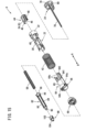
- the end cap 24, the injection spring 58, the plunger 82, the top 88, the end guide 68, the sleeve spring 42, the locking pin 44, the sleeve body 22, and the sliding member 64 illustrated in Figs. 8 , 9 , and 15 are assembled to constitute a drive unit U.
- the drive unit U has a locking mechanism R that blocks the movement of the plunger 82 in the distal direction caused by the injection spring 58.
- the locked state by the locking mechanism R is released, thereby allowing the plunger 82 to move in the distal direction.
- the end cap 24 is disposed on a proximal end of the drive unit U, and the end guide 68 and the top 88 are disposed on a distal end of the drive unit U (see Fig. 9 ).
- the first connections 66 of the sliding member 64 are disposed adjacent to the end guide 68.
- the drive unit U illustrated in Fig. 9 is inserted into the casing 12 from its proximal end.
- the drive unit U is inserted in such a manner that the first connections 66 and the second connections 123 of the coupling mechanism 19 are in a straight line along the axial direction (directions of arrows A and B).
- the proximal end of the drive unit U moves toward the proximal end of the needle cover 14, and the first connections 66 and the second connections 123 face each other in the axial direction (directions of arrows A and B) (see Fig. 16 ).
- the projection 123b of each second connection 123 is inserted into the housing recess 66a of each first connection 66 from the distal end of the cylindrical portion 64b.
- the projection 123b is inserted between the first flexible arm portion 67a and the second flexible arm portion 67b (see Fig. 17 ).
- the bevels 123d of the projection 123b come into contact with the first flexible arm portion 67a and the second flexible arm portion 67b, whereby the first flexible arm portion 67a and the second flexible arm portion 67b are pressed in directions away from each other along the circumferential direction of the cylindrical portion 64b. Accordingly, the first and second flexible arm portions 67a and 67b tilt to be separated from each other, having the fixed ends 671 and 672 functioning as fulcrums.
- the projection 123b and the extending end 123a are inserted into each housing recess 66a while the first and second flexible arm portions 67a and 67b are pushed out in the circumferential direction of the cylindrical portion 64b.
- the projection 123b passes over the free ends 673 and 674 of the first and second flexible arm portions 67a and 67b, the first flexible arm portion 67a and the second flexible arm portion 67b tilt by an elastic force in directions approaching each other (see the dot-dot-dash line in Fig. 17 ).
- each second connection 123 is engaged with proximal ends of the first and second flexible arm portions 67a and 67b, and the free ends 673 and 674 of the first and second flexible arm portions 67a and 67b are engaged with the jaws 123c of the projection 123b.
- the first connections 66 of the sliding member 64 and the second connections 123 of the needle cover 14 are coupled in the axial direction (directions of arrows A and B) by each projection 123b, each first flexible arm portion 67a, and each second flexible arm portion 67b.
- the needle cover 14 when the medicinal solution administration device 10 is dropped and an impact is applied to the needle cover 14, causing the needle cover 14 to move in the proximal direction, the engagement of the retaining arms 148 (outer hooks 150) with the engaging holes 120 are reliably maintained. With this configuration, the needle cover 14 is restricted from moving in the proximal direction relative to the casing 12.
- the retaining arms 148 (outer hooks 150) of the cap 18 function as a movement restricting mechanism 156 that restricts the movement of the needle cover 14 in the proximal direction relative to the casing 12.
- the coupling mechanism 19 reliably prevents the sliding member 64 from moving in the proximal direction. Accordingly, it is possible to reliably prevent erroneous actuation of the drive unit U attributed to an inertial force.
- the cap 18 is detached from the distal ends of the casing 12 and the needle cover 14.
- a patient holds the cylinder 20 of the casing 12 and pulls the cap 18 in a direction (direction of arrow B) in which the cap is separated from the casing 12.
- the cap 18 moves in a direction away from the distal end of the needle cover 14, and the outer hooks 150 moves in the distal direction (direction of arrow B) inside the engaging holes 120.
- the outer hooks 150 With the movement of the outer hooks 150 in the distal direction, the outer hooks 150 are positioned to face the recesses 28.
- the cap 18 is further pulled in the distal direction (direction of arrow B). Accordingly, as illustrated in Fig. 22 , the outer hooks 150 and the distal portions of the engaging holes 120 come into contact with each other, and the retaining arms 148 tilt radially outward.
- the retaining arms 148 including the outer hooks 150 move in the distal direction through the recesses 28 and the gaps between the cylinder 20 and the needle cover 14.
- the protective cover 128 retained by the inner hook 154 moves together with the cap 18. Accordingly, the protective cover 128 is detached from the needle retainer 134 of the barrel 124.
- the medicinal solution M is administered using the medicinal solution administration device 10 from which the cap 18 is detached.
- the relationship between the plunger 82 and the locking pin 44 is as illustrated in Fig. 7 .
- the locking pin 44 is inserted into the interior of the flexible portions 86 of the plunger 82, and the flexible portions 86 are restricted from tilting inward by the locking pin 44. In other words, the flexible portions 86 cannot tilt inward.
- the brims 96 of the flexible portions 86 are engaged with the protrusions 38 of the sleeve body 22, which prevents the plunger 82 from moving in the distal direction.
- the patient holds the casing 12 of the medicinal solution administration device 10 and presses the distal end of the needle cover 14 protruding from the distal end of the casing 12 against the skin S, or a desired puncture site, in such a manner that the distal end of the needle cover 14 is substantially perpendicular to the skin S.
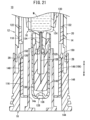
- the distal side and the proximal side of the medicinal solution administration device 10 are in states illustrated in Figs. 24 and 25 , respectively.
- the casing 12 is continuously pushed against the skin S (distal side, direction of arrow B).
- Figs. 26 and 27 illustrate a state where a needle tip of the puncture needle 126 has just started to touch the skin S.
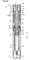
- the puncture needle 126 of the syringe 16 protrudes from the hole 14a of the needle cover 14 toward the distal side (direction of arrow B) as illustrated in Figs. 28 and 30 . Accordingly, the state is changed to a puncture completed state where the puncture needle 126 pierces the skin S and is inserted to a predetermined depth.
- the distal end of the cylinder 20 is substantially at the same position as the distal end of the needle cover 14.
- the ribs 119a of the needle cover 14 are in contact with the distal end of the sliding member 64. Therefore, in the process of state change from Fig. 23 to Fig. 28 , along with the movement of the needle cover 14 in the proximal direction relative to the casing 12 as described above, the sliding member 64 moves in the proximal direction relative to the casing 12. As illustrated in Figs. 27 and 29 , with the movement of the sliding member 64 in the proximal direction, the distal ends of the slits 641 of the sliding member 64 push the engaging ends 60 disposed on the distal ends of the arms 48 of the locking pin 44 in the proximal direction, whereby the locking pin 44 also moves in the proximal direction relative to the casing 12.
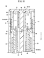
- the small diameter portion 54 of the locking pin 44 is separated from the interior of the flexible portions 86 of the plunger 82 in the proximal direction (direction of arrow A) as illustrated in Fig. 31 . Accordingly, the locked state of the plunger 82 by the locking pin 44 is released, and the plunger 82 starts moving in the distal direction (direction of arrow B) by an elastic force of the injection spring 58.
- the brims 96 of the plunger 82 pass over the protrusions 38, the brims 96 are displaced radially inward, and then, expand radially outward again by an elastic restoring force of the flexible portions 86, and outer edge portions come into contact with the inner periphery of the body main structure 30.
- the outside diameter D1 of the brims 96 is slightly larger than the inside diameter D2 of the body main structure 30 (see Fig. 7 ). Accordingly, when the brims 96 come into contact with the body main structure 30, a first notification sound, or a sound of contact (click), is generated.
- the plunger 82 After the plunger 82 starts moving in the distal direction and the brims 96 pass over the protrusions 38, the plunger 82 further moves in the distal direction, and the plunger 82 starts pressing the gasket 106.
- the medicinal solution M in the barrel 124 is pressed toward the distal end by the gasket 106. Accordingly, the medicinal solution M is ejected from the puncture needle 126, and the medicinal solution M is subcutaneously administered to the patient.
- the first notification sound is generated due to the brims 96 tapping the body main structure 30. The first notification sound enables the patient to recognize the start of administration of the medicinal solution M.
- the plunger 82 moves in the distal direction, the plunger 82 is introduced by each guiding rib 34 of the sleeve body 22 inserted into the four sliding grooves 92. Accordingly, when the plunger 82 moves toward the distal end, the plunger 82 moves along the axial direction without rotating.
- the gasket 106 attached to the top 88 is inserted into the barrel 124 of the syringe 16.
- the plunger 82 continuously moves in the distal direction (direction of arrow B) at a constant speed by an elastic force of the injection spring 58.
- the medicinal solution M is pushed out by the gasket 106 moving in the distal direction inside the barrel 124, and the medicinal solution M is ejected from the puncture needle 126.
- the plunger 82 further moves in the distal direction, and the flexible portions 86 reach a proximal end of the end guide 68.
- the brims 96 come into contact with the inclined guiding portions 72, and the brims 96 move in the distal direction (direction of arrow B) while rotating clockwise along the inclined guiding portions 72.
- the movement of the plunger 82 along the inclined guiding portions 72 of the end guide 68 applies a rotational force to the plunger 82.
- the rotation of the plunger 82 causes the engaging chips 98 disposed on its distal ends to move along the horizontal portions 110 in the introducing grooves 108 of the top 88.
- the plunger 82 reaches the distal ends of the guiding ribs 34 of the sleeve body 22, and the plunger 82 which is guided in the axial direction by the sliding grooves 92 and the guiding ribs 34 is released and becomes rotatable.
- the flexible portions 86 move in the distal direction while rotating along the inclined guiding portions 72 and reach the linear guiding portions 74.
- the plunger 82 administers a predetermined amount of the medicinal solution M in the barrel 124 to the skin S through the puncture needle 126, thereby completing the administration of the medicinal solution M.
- the guiding grooves 70 function as a guide unit that linearly moves the plunger 82 in the distal direction (direction of arrow B) after rotating the plunger 82 at a predetermined degree.
- the engaging chips 98 of the plunger 82 move toward the perpendicular portions 112 while rotating along the inclined portions 114.
- the engaging chips 98 of the plunger 82 move along the perpendicular portions 112, thereby moving again in the axial direction toward the distal direction (direction of arrow B).
- distal surfaces of the engaging chips 98 moved along the perpendicular portions 112 of the introducing grooves 108 come into contact with distal edges of the perpendicular portions 112, which causes a second notification sound, or a sound of contact (click).
- the second notification sound is generated a predetermined time later.
- the second notification sound enables the patient to recognize the completion of medicinal solution administration to the affected area (skin S). After the patient recognizes the second notification sound, the patient separates the medicinal solution administration device 10 from the affected area.
- the plunger 82 is rotated by the guiding grooves 70 of the end guide 68 to decelerate the moving speed in the axial direction. This delays the time for the gasket 106 of the top 88 connected to the plunger 82 to reach the distal end of the barrel 124.
- the second notification sound is generated a predetermined time later to notify the completion of medicinal solution administration.
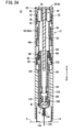
- the sliding member 64 When the patient releases a pressing force of the medicinal solution administration device 10 against the skin S, the sliding member 64 is biased toward the distal end by an elastic force of the sleeve spring 42 as illustrated in Fig. 37 .
- the distal end of the sliding member 64 is in contact with the ribs 119a (see Fig. 11 ) of the needle cover 14, whereby the sliding member 64 pushes the needle cover 14 in the distal direction and moves in the distal direction relative to the casing 12 together with the needle cover 14.
- the needle cover 14 moves to a position where the distal end of the needle cover 14 moves further in the distal direction than the puncture needle 126. Accordingly, the puncture needle 126 is completely covered by the needle cover 14.
- the protruding pieces 642 of the sliding member 64 are engaged with the protrusive portions 48a of the locking pin 44, and the locking pin 44 moves in the distal direction (direction of arrow B) together with the sliding member 64.
- the locking claws 62 are engaged with the locking grooves 40 of the sleeve body 22. Accordingly, the movement of the locking pin 44 in the proximal direction relative to the sleeve body 22 is restricted.
- the sliding member 64 abuts on the arms 48 of the locking pin 44, and the movement of the sliding member 64 in the proximal direction is also restricted.
- the extending portions 119 (ribs 119a) of the needle cover 14 abut on the distal end of the sliding member 64, and the movement of the needle cover 14 in the proximal direction is also restricted.
- the needle cover 14 is restricted from moving in the proximal direction. For this reason, even when a force in the proximal direction acts on the needle cover 14, the puncture needle 126 is secured and not exposed to the outside from the needle cover 14.
- the drive unit U is capable of biasing the gasket 106 of the syringe 16 toward the distal end by the plunger 82 along with the movement of the needle cover 14 in the proximal direction, and the proximal end of the needle cover 14 and the drive unit U are connected to each other in the axial direction by the coupling mechanism 19. Therefore, when the medicinal solution administration device 10 is dropped from the cap 18 side, the movement restricting mechanism 156 prevents the needle cover 14 from moving in the proximal direction relative to the cap 18, and when an inertial force acts on the drive unit U in the proximal direction, the drive unit U (sliding member 64) coupled to the needle cover 14 by the coupling mechanism 19 does not move in the proximal direction.
- the needle cover 14 is reliably prevented from moving in the proximal direction, and the drive unit U connected to the needle cover 14 is prevented from moving in the proximal direction, which prevents the erroneous actuation of the drive unit U.
- the proximal end of the needle cover 14 can be reliably coupled to the distal end of the drive unit U in the axial direction by the first connections 66 of the drive unit U and the second connections 123 of the needle cover 14. Therefore, when the needle cover 14 is biased in the proximal direction by inertia at the time of dropping the medicinal solution administration device 10, the needle cover 14 is reliably prevented from moving in the proximal direction (direction of arrow A).
- the drive unit U includes the sliding member 64 that is movable along the axial direction of the casing 12 and the sleeve spring 42 that biases the sliding member 64 toward the syringe 16, and the first connections 66 are disposed on the sliding member 64. Accordingly, coupling the second connections 123 of the needle cover 14 to the first connections 66 disposed on the sliding member 64 makes it possible to couple the needle cover 14 to the sliding member 64 reliably, thereby preventing the sliding member 64 from moving in the proximal direction (direction of arrow A) when the medicinal solution administration device 10 is dropped.
- each first connection 123 When assembling the medicinal solution administration device 10, the first and second flexible arm portions 67a and 67b of each first connection 123 are elastically deformed by the projection 123b of each second connection 66 protruding in the direction perpendicular to the axial direction of the casing 12, and the projection 123b is engaged with the first and second flexible arm portions 67a and 67b. Accordingly, the first connections 66 and the second connections 123 are coupled to each other, which reliably prevents the sliding member 64 from moving in the proximal direction (direction of arrow A).
- the proximal end of the needle cover 14 is provided with the extending portions 119 protruding toward the proximal end, the projection 123b of each second connection 123 is disposed on the proximal end of each extending portion 119, and the projection 123b protrudes toward both sides of each extending portion 119 in the width direction perpendicular to the direction of extension of the extending portions 119. Therefore, the needle cover 14 can be coupled to the first connections 66 of the drive unit U at the most proximal side of the needle cover 14, and the needle cover 14 and the drive unit U can be reliably coupled at an initial stage of assembly of the needle cover 14 and the drive unit U.
- the second connections 123 can be connected to the first connections 66 more firmly by engaging the projection 123b of each second connection 123 protruding toward both sides in the width direction perpendicular to the axial direction, or a direction of assembly, with each first connection 66.
- the first flexible arm portion 67a and the second flexible arm portion 67b of each first connection 66 are arranged in pairs, being separated from each other along the circumferential direction of the cylindrical portion 64b disposed on the proximal end of the sliding member 64, and the first flexible arm portion 67a and the second flexible arm portion 67b have a cantilever structure in which the distal ends of the first flexible arm portion 67a and the second flexible arm portion 67b are connected to the distal end of the cylindrical portion 64b.
- each second connection 123 when the extending portion 119 of each second connection 123 is inserted between the pair of first flexible arm portion 67a and the second flexible arm portion 67b, the first flexible arm portion 67a and the second flexible arm portion 67b are elastically deformed by the projection 123b in directions away from each other along the circumferential direction of the cylindrical portion 64b with the distal ends functioning as fulcrums, and when the projection 123b reaches the proximal ends of the first and second flexible arm portions 67a and 67b, the projection 123b is engaged with the proximal ends.
- the projection 123b is engaged with the proximal ends of the pair of first and second flexible arm portions 67a and 67b, and the first and second flexible arm portions 67a and 67b and the projection 123b are coupled in the axial direction, thereby preventing the movement of the sliding member 64 in the proximal direction (direction of arrow A).
- the needle cover 14 includes the ribs 119a protruding in a direction opposite to the casing 12 and locked by the distal end of the sliding member 64. Accordingly, when the needle cover 14 is moved in the proximal direction (direction of arrow A) due to the distal end of the needle cover 14 being pressed against the skin S, the ribs 119a come into contact with the distal end of the sliding member 64 and the sliding member 64 is pushed up in the proximal direction by the needle cover 14, which allows the drive unit U to actuate.
- a coupling mechanism 160 may be employed in a medicinal solution administration device 162.
- the coupling mechanism 160 includes a first connection 164 disposed in a cylindrical portion 64b of a sliding member 64 and a second connection 166 disposed on a proximal end of a needle cover 14.
- the first connection 164 includes a protrusion 168 on the inner periphery of a housing recess 66a.
- the protrusion 168 has a circular shape and protrudes radially outward from the inner periphery of the housing recess 66a.
- a top of the protrusion 168 has a bevel 168a extending radially outward from a proximal end toward a distal end of the sliding member 64.
- the second connection 166 has an insertion hole (hole) 170 on a proximal end of an extending portion 119 in the needle cover 14.
- the insertion hole 170 has a circular shape.
- the insertion hole 170 penetrates the extending portion 119 and allows insertion of the protrusion 168 of the first connection 164.
- the protrusion 168 of the first connection 164 in a drive unit U is inserted into the insertion hole 170 of the second connection 166 of the needle cover 14, whereby the first connection 164 of the sliding member 64 and the second connection 166 of the needle cover 14 are coupled to each other in the axial direction. Accordingly, when the medicinal solution administration device 162 is dropped and a load is applied to a distal end, the protrusion 168 reliably prevents the sliding member 64 from moving in the proximal direction (direction of arrow A).
- the extending portion 119 tilts gradually and radially outward while being in contact with the bevel 168a, and when the protrusion 168 and the insertion hole 170 face each other, the protrusion 168 is easily and reliably inserted into the insertion hole 170.
- a medicinal solution administration device (10, 162) includes:
- the coupling mechanism includes
- the drive unit includes
- the second connection (123) has a projection (123b) protruding in a direction perpendicular to the axial direction of the casing, and the first connection (66) has a flexible arm portion (67a, 67b) engaged with the projection and elastically deformable by contact with the projection.
- the second connection (166) has a hole (170) opened in a direction perpendicular to the axial direction of the casing, and the first connection (164) has a protrusion (168) protruding toward the second connection and engaged with the hole.
- the proximal end of the needle cover is provided with an extending portion (119) further protruding toward the proximal end, the projection of the second connection is disposed on a proximal end of the extending portion, and the projection protrudes toward both sides of the extending portion in a width direction perpendicular to a direction of extension of the extending portion.
- the sliding member has a proximal end including a cylindrical portion (64b) whose distal end is provided with the first connection, and the second connection is provided with a pair of flexible arm portions separated from each other along a circumferential direction of the cylindrical portion, the flexible arm portions having a cantilever structure in which distal ends of the flexible arm portions are connected to the distal end of the cylindrical portion, the flexible arm portions being inclined from the distal ends toward proximal ends of the flexible arm portions, and one flexible arm portion and the other flexible arm portion approaching each other toward the proximal ends.
- the needle cover includes a rib (119a) protruding in a direction opposite to the casing and locked by a distal end of the sliding member.
Landscapes
- Health & Medical Sciences (AREA)
- Engineering & Computer Science (AREA)
- Hematology (AREA)
- Anesthesiology (AREA)
- Biomedical Technology (AREA)
- Heart & Thoracic Surgery (AREA)
- Vascular Medicine (AREA)
- Life Sciences & Earth Sciences (AREA)
- Animal Behavior & Ethology (AREA)
- General Health & Medical Sciences (AREA)
- Public Health (AREA)
- Veterinary Medicine (AREA)
- Environmental & Geological Engineering (AREA)
- Infusion, Injection, And Reservoir Apparatuses (AREA)
Abstract
Description
- The present invention relates to a medicinal solution administration device for administering a medicinal solution to a pierced living body.
- In the related art, there is known a portable medicinal solution administration device which is used for a subcutaneous injection to pierce the skin of a user (patient), or a target of administration, and administer a medicinal solution. A medicinal solution administration device disclosed in
JP 6334717 B1 - In a case where the medicinal solution administration device is accidentally dropped on the floor or the like from the cover cap side before the medicinal solution is administered by the medicinal solution administration device, the triggering member is pushed up in a direction away from the distal end due to an impact applied to the cover cap. In this instance, an arm of the triggering member comes into contact with a stopper of the casing and restricts the movement of the triggering member toward the proximal side. This configuration prevents erroneous actuation of a drive unit that drives a gasket (piston) inside the syringe in a distal direction.
- In the aforementioned medicinal solution administration device, the movement of the triggering member toward the proximal end is restricted by the stopper but the drive unit for driving the gasket is not restricted at all. For this reason, when the medicinal solution administration device is accidentally dropped on the floor or the like from the cover cap side, it is conceivable that a part of the drive unit moves inside the casing due to an inertial force and that the drive unit is actuated and pushes the piston (the drive unit actuates erroneously).
- An object of the present invention is to solve the problem.
- An aspect of the present invention includes:
- a casing formed into a hollow cylindrical shape;
- a syringe including a cylinder that is housed in the casing and filled with a medicinal solution and a puncture needle that is communicated with the cylinder and administers the medicinal solution to a living body;
- a needle cover having a hollow cylindrical shape that is disposed inside the casing and covers a distal side of the syringe and displaces in a proximal direction relative to the casing when being pressed against a puncture target;
- a cap that is detachably disposed on a distal end of the needle cover and detached when the puncture target is punctured with the puncture needle; and
- a drive unit that is housed on a proximal side of the casing and biases a gasket of the syringe toward a distal end of the casing by a plunger along with movement of the needle cover in the proximal direction, wherein
- the drive unit includes a locking mechanism that blocks the plunger from moving in a distal direction in an initial state and allows the plunger to move in the distal direction along with the movement of the needle cover in the proximal direction, and
- the medicinal solution administration device includes
- a movement restricting mechanism that restricts the movement of the needle cover in the proximal direction relative to the casing when the cap is attached and allows the movement of the needle cover in the proximal direction when the cap is detached from the casing and
- a coupling mechanism that couples a proximal end of the needle cover and the drive unit to each other in an axial direction.
- According to the present invention, when the medicinal solution administration device is dropped from the cap side, the movement restricting mechanism prevents the movement of the needle cover in the proximal direction relative to the cap, and when an inertial force acts on the drive unit, the coupling mechanism is involved to prevent the drive unit from moving in the proximal direction relative to the needle cover. With this configuration, even when the medicinal solution administration device is dropped, the drive unit is not activated and the gasket is not pushed by the plunger. In other words, it is possible to reliably prevent erroneous actuation of the drive unit.
-
-
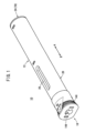
Fig. 1 is an external perspective view of a medicinal solution administration device according to an embodiment of the present invention. -
Fig. 2 is an exploded perspective view of the medicinal solution administration device illustrated inFig. 1 . -
Fig. 3 is an overall cross-sectional view of the medicinal solution administration device illustrated inFig. 1 . -
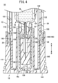
Fig. 4 is an enlarged cross-sectional view illustrating a distal end and its neighboring parts of the medicinal solution administration device illustrated inFig. 3 . -
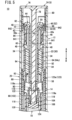
Fig. 5 is an enlarged cross-sectional view illustrating a proximal end and its neighboring parts of the medicinal solution administration device illustrated inFig. 3 . -
Fig. 6 is an overall cross-sectional view illustrating another cross section of the medicinal solution administration device illustrated inFig. 3 . -
Fig. 7 is an enlarged cross-sectional view illustrating the proximal end and its neighboring parts of the medicinal solution administration device illustrated inFig. 6 . -
Fig. 8 is a partially omitted external perspective view of the medicinal solution administration device illustrated inFig. 1 . -
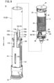
Fig. 9 is an exploded perspective view of a drive unit disassembled from a casing in the medicinal solution administration device illustrated inFig. 8 . -
Fig. 10 is an enlarged perspective view illustrating a first connection and its neighboring parts of the medicinal solution administration device illustrated inFig. 9 . -
Fig. 11 is an enlarged perspective view illustrating a second connection and its neighboring parts of the medicinal solution administration device illustrated inFig. 9 . -
Fig. 12 is an enlarged perspective view illustrating a coupling mechanism and its neighboring parts of the medicinal solution administration device illustrated inFig. 8 . -
Fig. 13 is an enlarged front view of the coupling mechanism and its neighboring parts illustrated inFig. 12 . -
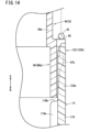
Fig. 14 is a cross-sectional view taken along line XIV-XIV inFig. 13 . -
Fig. 15 is an exploded perspective view of the drive unit illustrated inFigs. 8 and9 . -
Fig. 16 is an enlarged front view illustrating a state before coupling the first connection and the second connection of the coupling mechanism illustrated inFig. 13 . -
Fig. 17 is an enlarged front view illustrating a state where the first connection and the second connection of the coupling mechanism illustrated inFig. 16 are being coupled. -
Fig. 18A is a partially cutaway enlarged perspective view illustrating a state where a proximal end of a plunger is inserted into a guiding groove of an end guide, andFig. 18B is a view for illustrating an action around a distal end of the plunger illustrated inFig. 18A . -
Fig. 19A is a partially cutaway enlarged perspective view illustrating a state where the plunger starts to rotate along an inclined guiding portion, andFig. 19B is a view for illustrating an action around the distal end of the plunger illustrated inFig. 19A . -
Fig. 20A is a partially cutaway enlarged perspective view illustrating a state where the plunger moves in a distal direction along a linear guiding portion, andFig. 20B is a view for illustrating an action around the distal end of the plunger illustrated inFig. 20A . -
Fig. 21 is an enlarged cross-sectional view illustrating a state where a cap in the medicinal solution administration device illustrated inFig. 4 is pulled in the distal direction. -
Fig. 22 is an enlarged cross-sectional view of the cap illustratedFig. 21 , illustrating a state where a proximal end of a retaining arm of the cap tilts radially outward. -
Fig. 23 is an overall cross-sectional view illustrating a state where the cap is detached from the medicinal solution administration device illustrated inFig. 3 . -
Fig. 24 is an enlarged cross-sectional view illustrating the distal end and its neighboring parts of the medicinal solution administration device illustrated inFig. 23 . -
Fig. 25 is an enlarged cross-sectional view illustrating the proximal end and its neighboring parts of the medicinal solution administration device illustrated inFig. 23 . -
Fig. 26 is an overall cross-sectional view illustrating a state where the medicinal solution administration device illustrated inFig. 23 starts skin puncture. -
Fig. 27 is an enlarged cross-sectional view illustrating the proximal end and its neighboring parts of the medicinal solution administration device illustrated inFig. 26 . -
Fig. 28 is an overall cross-sectional view illustrating a state where the medicinal solution administration device illustrated inFig. 26 completes the skin puncture. -
Fig. 29 is an enlarged cross-sectional view illustrating the proximal end and its neighboring parts of the medicinal solution administration device illustrated inFig. 28 . -
Fig. 30 is an overall cross-sectional view illustrating another cross section of the medicinal solution administration device illustrated inFig. 28 after the puncture. -
Fig. 31 is an enlarged cross-sectional view illustrating the proximal end and its neighboring parts of the medicinal solution administration device illustrated inFig. 29 . -
Fig. 32 is an overall cross-sectional view illustrating a state where the plunger in the medicinal solution administration device illustrated inFig. 31 starts moving in the distal direction. -
Fig. 33 is an enlarged cross-sectional view illustrating the proximal end and its neighboring parts of the medicinal solution administration device illustrated inFig. 32 . -
Fig. 34 is an overall cross-sectional view illustrating a state where the plunger in the medicinal solution administration device illustrated inFig. 28 further moves in the distal direction and completes medicinal solution administration. -
Fig. 35 is an enlarged cross-sectional view illustrating the proximal end of the plunger and its neighboring parts of the medicinal solution administration device illustrated inFig. 34 . -
Fig. 36 is an overall cross-sectional view illustrating a state where the plunger in the medicinal solution administration device illustrated inFig. 34 after the medicinal solution administration further moves in the distal direction. -
Fig. 37 is an overall cross-sectional view illustrating a state where a puncture needle moves in a proximal direction and is housed in a needle cover in the medicinal solution administration device illustrated inFig. 36 . -
Fig. 38 is an enlarged cross-sectional view illustrating the proximal end and its neighboring parts of the medicinal solution administration device illustrated inFig. 37 . -
Fig. 39A is an enlarged front view of a medicinal solution administration device having a coupling mechanism according to a modification, andFig. 39B is an enlarged front view illustrating a state before the coupling mechanism illustrated inFig. 39A is coupled. -
Fig. 40 is a cross-sectional view taken along line XL-XL inFig. 39A . - Hereinafter, preferred embodiments of the present invention will be described in detail with reference to the accompanying drawings.
- A medicinal
solution administration device 10 is used, for example, for administering a medicinal solution M subcutaneously to a patient, or a user. As illustrated inFigs. 1 to 5 , the medicinalsolution administration device 10 includes acasing 12 formed into a hollow cylindrical shape, aneedle cover 14 movably housed in thecasing 12, asyringe 16 housed in theneedle cover 14, acap 18 detachably disposed on a distal end of thecasing 12, and acoupling mechanism 19 that couples theneedle cover 14 and a slidingmember 64 to be described. - The
casing 12 is formed of a resin material and has a circular cross section. Thecasing 12 includes acylinder 20 having an outside diameter and an inside diameter substantially constant along the axial direction (directions of arrows A and B), asleeve body 22 housed in thecylinder 20 on the proximal side (direction of arrow A), and anend cap 24 that closes a proximal end of thecylinder 20. - The
cylinder 20 has a predetermined length in the axial direction (directions of arrows A and B). Thecylinder 20 has an opened distal end and opened proximal end. Thecylinder 20 has the peripheral wall provided with aviewing window 26. Theviewing window 26 penetrates the peripheral wall of thecylinder 20 and is opened at a position corresponding to a position of abarrel 124 of thesyringe 16 housed in thecylinder 20. The medicinal solution M in thebarrel 124 can be checked through theviewing window 26. - A pair of
recesses 28 is formed on the distal end of the cylinder 20 (seeFig. 4 ). Therecesses 28 have a rectangular cross section and are depressed radially with respect to the inner periphery of thecylinder 20. The pair ofrecesses 28 is symmetric about the axis of thecylinder 20 on the outer periphery of thecylinder 20. When thecap 18 is attached to the distal end of thecylinder 20, therecesses 28 are placed at positions facing retainingarms 148 of thecap 18. - The
sleeve body 22 is formed into a hollow shape. Thesleeve body 22 includes a bodymain structure 30 formed into a cylindrical shape and anenlarged diameter portion 32 formed on the proximal side of the body main structure 30 (direction of arrow A). The bodymain structure 30 has a substantially constant diameter along the axial direction (directions of arrows A and B). The bodymain structure 30 has the inner periphery provided with four guidingribs 34 protruding radially inward. - The guiding
ribs 34 are separated from each other at 90-degree intervals along the circumferential direction of the bodymain structure 30. The number of guidingribs 34 is not limited to four. There are at least three guidingribs 34. The guidingribs 34 have a substantially constant thickness, protruding linearly and radially inward from the inner periphery of the bodymain structure 30. The guidingribs 34 have the same radially protruding length. The guidingribs 34 face each other in pairs across the central axis of the bodymain structure 30. - As illustrated in
Figs. 2 ,3 , and5 , thesleeve body 22 houses a lockingpin 44 and aplunger 82 to be described in a movable manner in the axial direction. As illustrated inFigs. 6 and7 , a boundary between theenlarged diameter portion 32 and the bodymain structure 30 is provided with a plurality ofprotrusions 38 protruding radially inward. Theprotrusions 38 have a rectangular cross section and protrude radially outward from the inner periphery of the bodymain structure 30. Proximal ends of theprotrusions 38 are bevels that are inclined gradually and radially inward (seeFig. 7 ). - As illustrated in
Figs. 6 and7 , theprotrusions 38 are engaged withbrims 96 offlexible portions 86 in theplunger 82 to be described on the proximal side (direction of arrow A). The number and arrangement of theprotrusions 38 correspond to the number and arrangement of theflexible portions 86. - The
sleeve body 22 is housed in thecylinder 20 from the proximal end of thecylinder 20, and theenlarged diameter portion 32 is engaged with an inner peripheral portion of thecylinder 20. Accordingly, a proximal end of theenlarged diameter portion 32 is housed and fixed at a position closer to the distal side (direction of arrow B) than the proximal end of thecylinder 20 by a predetermined distance. - As illustrated in
Figs. 2 ,3 , and5 , the bodymain structure 30 has the outer periphery provided with a pair of lockinggrooves 40 that is depressed radially inward. The pair of lockinggrooves 40 is symmetric about the central axis of thesleeve body 22, and the lockinggrooves 40 are engaged with lockingclaws 62 of the lockingpin 44 to be described. - A
sleeve spring 42 is disposed between the outer periphery of the bodymain structure 30 and the inner periphery of thecylinder 20. Thesleeve spring 42 is an elastic member composed of a coil spring. A proximal end of thesleeve spring 42 is engaged with a distal end of theenlarged diameter portion 32. A distal end of thesleeve spring 42 is engaged with the slidingmember 64 to be described. An elastic force of thesleeve spring 42 biases the slidingmember 64 in a direction away from thesleeve body 22, that is, in the distal direction (direction of arrow B). - The
sleeve body 22 houses the lockingpin 44 that straddles theenlarged diameter portion 32 and the bodymain structure 30. - The locking
pin 44 is movable in the axial direction (directions of arrows A and B) inside thesleeve body 22. The lockingpin 44 includes a cylindrical pinmain structure 46 formed at the center and a pair ofarms 48 disposed on the outer periphery of the pinmain structure 46. Thearms 48 are connected to a proximal end of the pinmain structure 46 in an integrated manner. - The pin
main structure 46 includes aflat end wall 50 formed on the proximal end and perpendicular to the axial direction, alarge diameter portion 52 extending from the center of theend wall 50 toward the distal side (direction of arrow B), and asmall diameter portion 54 formed on the distal side of the large diameter portion 52 (direction of arrow B) with a diameter smaller than that of thelarge diameter portion 52. The pinmain structure 46 has ahole 56 on the central axis. Thehole 56 extends along the axial direction with a constant diameter, linearly penetrating theend wall 50, thelarge diameter portion 52, and thesmall diameter portion 54. Into thehole 56, ashaft 78 of theend cap 24 and aninjection spring 58 to be described are inserted. - Proximal ends of the
arms 48 are connected to theend wall 50 of the pinmain structure 46 and are arranged in parallel at a predetermined interval on the outer periphery of the pinmain structure 46. Thearms 48 have the same length, extending toward the distal end (direction of arrow B). Distal ends of thearms 48 have engaging ends 60 engaged with the slidingmember 64 to be described and the lockingclaws 62 formed on the radially inner side of the engaging ends 60. - The engaging ends 60 have a flat shape perpendicular to a direction of extension of the
arms 48. The lockingclaws 62 protrude radially inward from the engaging ends 60 and toward the distal side (direction of arrow B). The lockingclaws 62 have a triangular cross-sectional shape tapered toward the distal ends of thearms 48. - Centers of the
arms 48 in the longitudinal direction are provided withprotrusive portions 48a that protrude outward. Theprotrusive portions 48a protrude outward from outer surfaces of thearms 48 and have a rectangular shape elongated in a direction perpendicular to the direction of extension of thearms 48. Theprotrusive portions 48a are inserted intoslits 641 of the slidingmember 64 to be described. - Inside the
cylinder 20, thecylindrical sliding member 64 is disposed on the distal side (direction of arrow B) of the lockingpin 44. - The sliding
member 64 is movable in the axial direction (directions of arrows A and B) inside thecylinder 20. Theplunger 82 and the bodymain structure 30 of thesleeve body 22 are inserted into the slidingmember 64. - As illustrated in
Fig. 15 , the slidingmember 64 includes a cylindrical sleevemain structure 64a, acylindrical portion 64b disposed on a distal end of the sleevemain structure 64a, and a pair of engagingarms 64c extending from a proximal end of the sleevemain structure 64a. Thecylindrical portion 64b increases in diameter as compared with the sleevemain structure 64a. That is, the diameter of thecylindrical portion 64b is larger than that of the sleevemain structure 64a. A boundary between the sleevemain structure 64a and thecylindrical portion 64b has a steppedcatcher 65. As illustrated inFig. 8 , thecatcher 65 retains the distal end of thesleeve spring 42 disposed on the outer periphery of the slidingmember 64. An elastic force of thesleeve spring 42 biases the slidingmember 64 toward the distal end. - As illustrated in
Fig. 10 , thecylindrical portion 64b hasfirst connections 66 as part of thecoupling mechanism 19. Thefirst connections 66 are disposed in pairs, being apart from each other along the circumferential direction of thecylindrical portion 64b. Thefirst connections 66 are symmetric about the axis of the slidingmember 64. Eachfirst connection 66 has ahousing recess 66a and first and secondflexible arm portions housing recess 66a. Eachhousing recess 66a is depressed radially inward from the outer periphery of thecylindrical portion 64b and is open from a distal end of thecylindrical portion 64b toward a proximal end. As illustrated inFig. 13 , eachhousing recess 66a has a trapezoidal shape narrowed toward a proximal end of the slidingmember 64. In other words,side walls housing recess 66a in the circumferential direction of thecylindrical portion 64b are inclined inward from the distal end toward the proximal end. - The first and second
flexible arm portions cylindrical portion 64b and are respectively arranged along theinclined side walls housing recess 66a. The firstflexible arm portion 67a and the secondflexible arm portion 67b are symmetrical about the center of eachhousing recess 66a. The first and secondflexible arm portions side walls housing recess 66a while being separated from theside walls - One ends (ends in the direction of arrow B) of the first and second
flexible arm portions ends cylindrical portion 64b. The first and secondflexible arm portions angle 8, having the fixed ends 671 and 672 of the first and secondflexible arm portions flexible arm portions free ends cylindrical portion 64b. The fixed ends 671 and 672 of the first and secondflexible arm portions cylindrical portion 64b than the free ends 673 and 674. - The first and second
flexible arm portions flexible arm portions flexible arm portions flexible arm portions flexible arm portion 67a and the secondflexible arm portion 67b have the same length. - Each
housing recess 66a has a space between the firstflexible arm portion 67a and the secondflexible arm portion 67b. Each space houses asecond connection 123 of theneedle cover 14, that is, part of thecoupling mechanism 19. - As illustrated in
Fig. 15 , in the slidingmember 64, the pair of engagingarms 64c is symmetric about the axis of the slidingmember 64, and eachengaging arm 64c protrudes in the proximal direction of the slidingmember 64. The engagingarms 64c have theslits 641. Theslits 641 have a rectangular shape along a direction of extension of the engagingarms 64c. Proximal ends of theslits 641 have protrudingpieces 642 protruding from proximal ends of the engagingarms 64c toward distal ends. The protrudingpieces 642 are inclined inward toward the distal ends. - As illustrated in
Fig. 5 , a part of eacharm 48 of the lockingpin 44 is inserted into eachslit 641. The engaging ends 60 of the lockingpin 44 can be engaged with distal ends of theslits 641. Theprotrusive portions 48a of thearms 48 can be engaged with the protrudingpieces 642. Accordingly, the lockingpin 44 is engaged with the slidingmember 64, and the lockingpin 44 is prevented from being detached from the slidingmember 64 in the proximal direction. - As illustrated in
Fig. 8 , anend guide 68 is disposed to face a distal end of the slidingmember 64. Theend guide 68 has a cylindrical shape having a diameter substantially equal to that of the slidingmember 64. As illustrated inFig. 5 , theplunger 82 is inserted into theend guide 68 in a movable manner in the axial direction. - As illustrated in
Fig. 18A , guidinggrooves 70 for rotating theplunger 82 are disposed on the inner periphery of theend guide 68. The guidinggrooves 70 are depressed radially outward with respect to the inner periphery of theend guide 68. Thebrims 96 of theflexible portions 86 of theplunger 82 to be described are inserted into the guidinggrooves 70. The guidinggrooves 70 are arranged at four places at equal intervals in the circumferential direction, corresponding to the number and arrangement of theflexible portions 86. - As illustrated in
Fig. 19A , each guidinggroove 70 includes an inclined guidingportion 72 and a linear guidingportion 74. Theinclined guiding portions 72 are inclined in the distal direction (direction of arrow B) with respect to the axial direction (directions of arrows A and B) of theend guide 68. Thelinear guiding portions 74 extend in a straight line from distal ends of the inclined guidingportions 72. A width along the circumferential direction of thelinear guiding portions 74 is substantially equal to or slightly larger than a width of thebrims 96 of theplunger 82 to be described. - As illustrated in
Fig. 5 , theend cap 24 has alid 76 that closes the proximal end of thecylinder 20 and theshaft 78 extending from the center of thelid 76 toward the distal side (direction of arrow B). Thelid 76 has a disk-like shape having the same diameter as the outside diameter of thecylinder 20. - The
lid 76 has apusher 80 protruding from an end face on the distal side. Thepusher 80 is formed into an annular shape protruding from the end face of thelid 76. When thepusher 80 abuts on the proximal end of theenlarged diameter portion 32 of thesleeve body 22, thesleeve body 22 housed in thecylinder 20 is restricted from moving in the proximal direction (direction of arrow A) and retained. - The
shaft 78 is a shaft body extending toward the distal side (direction of arrow B) along the axial direction. Theshaft 78 is housed in thecylinder 20 and thesleeve body 22, extending to a part near the center of thecylinder 20 in the axial direction. Theinjection spring 58 and theplunger 82 are allowed to pass through the outer periphery of theshaft 78. Theinjection spring 58 is a coil spring, having an elongated shape corresponding to the axial length of theshaft 78. Theinjection spring 58 is interposed between theplunger 82 to be described and the end face of thelid 76, and an elastic force of theinjection spring 58 biases theplunger 82 in the distal direction (direction of arrow B). - When the
end cap 24 is attached to the proximal end of thecylinder 20, the opened proximal end is closed by thelid 76 and theshaft 78 is disposed on the axis of thecylinder 20. - As illustrated in
Figs. 2 and5 , theplunger 82 has a cylindrical shape elongated in the axial direction (directions of arrows A and B). Theplunger 82 includes a rodmain structure 84 having a constant diameter along the axial direction, a plurality offlexible portions 86 formed on the proximal side (direction of arrow A) of the rodmain structure 84 and divided in the circumferential direction, and an attachingportion 90 formed on the distal side (direction of arrow B) of the rodmain structure 84 and to which a top 88 to be described is attached. - The rod
main structure 84 has a circular cross section. As illustrated inFig. 2 , the rodmain structure 84 has the outer periphery provided with four slidinggrooves 92 that are depressed radially inward. The slidinggrooves 92 have a rectangular cross section and are depressed with respect to the outer periphery of the rodmain structure 84. As illustrated inFig. 5 , the guidingribs 34 of thesleeve body 22 are inserted into the slidinggrooves 92. The slidinggrooves 92 are separated at equal intervals in the circumferential direction, corresponding to the number and arrangement of the guidingribs 34. The slidinggrooves 92 correspond to the four guidingribs 34. - When the
plunger 82 is housed in thesleeve body 22, distal ends of the guidingribs 34 are inserted into the slidinggrooves 92. - The inside of the rod
main structure 84 has afirst rod hole 94 extending along the axial direction (directions of arrows A and B). Into thisfirst rod hole 94, theshaft 78 of theend cap 24 and theinjection spring 58 are inserted. - The
flexible portions 86 protrude in the axial direction (direction of arrow A) from a proximal end of the rodmain structure 84 and are separated from each other in the circumferential direction. Eachflexible portion 86 is disposed between two adjacent slidinggrooves 92. The distal side (direction of arrow B) of theflexible portions 86 connected to the rodmain structure 84 functions as a fulcrum, and the proximal side (direction of arrow A) of theflexible portions 86 is radially tiltable. As illustrated inFig. 7 , proximal ends of theflexible portions 86 are provided with thebrims 96 protruding radially outward. Surfaces of thebrims 96 on the distal side (direction of arrow B) are bevels that are inclined gradually and radially outward toward the proximal side. - The
flexible portions 86 have a diameter increasing radially outward from the rodmain structure 84. Thesmall diameter portion 54 of the lockingpin 44 is inserted into the interior of theflexible portions 86. The inner peripheral diameter of theflexible portions 86 is larger than that of thefirst rod hole 94. - As illustrated in
Fig. 7 , thebrims 96 of theflexible portions 86 have an outside diameter D1 slightly larger than an inside diameter D2 of the bodymain structure 30 of the sleeve body 22 (D1 > D2). - As illustrated in
Fig. 15 , the attachingportion 90 has a small diameter with respect to the rodmain structure 84. The outer periphery of the attachingportion 90 is provided with a pair of engagingchips 98 protruding radially outward. The pair of engagingchips 98 is engaged with the top 88 to be described. The engagingchips 98 extend in the horizontal direction perpendicular to the axial direction of theplunger 82, being symmetric about the central axis of theplunger 82. - As illustrated in
Fig. 5 , the attachingportion 90 includes a second rod hole 100 extending along the axial direction (directions of arrows A and B). The second rod hole 100 is smaller in diameter than thefirst rod hole 94, and theshaft 78 of theend cap 24 is inserted through the second rod hole 100. A distal end of theinjection spring 58 is engaged with a stepped portion formed at a boundary between the second rod hole 100 and thefirst rod hole 94. Accordingly, an elastic force of theinjection spring 58 biases theplunger 82 in a direction away from theend cap 24, that is, in the distal direction (direction of arrow B) . - As illustrated in
Fig. 5 , the top 88 has a cup-like shape with the proximal side (direction of arrow A) opened. The top 88 is rotatable relative to the attachingportion 90 of theplunger 82. The top 88 includes acylindrical cup portion 102 disposed on the proximal side and a mountingportion 104 protruding from a distal end of thecup portion 102. Agasket 106 formed of an elastic material is attached to the top 88 so as to cover the outer periphery of the mountingportion 104. - The attaching
portion 90 of theplunger 82 is inserted into thecup portion 102 from the proximal side. As illustrated inFig. 18B , the outer periphery of thecup portion 102 is provided with a pair of introducinggrooves 108 which penetrates thecup portion 102 radially and through which the engagingchips 98 of theplunger 82 are inserted. - The introducing
grooves 108 are arranged in pairs, being symmetric about the central axis of thecup portion 102. Each introducinggroove 108 includes ahorizontal portion 110 formed near a proximal end of thecup portion 102 and extending along the circumferential direction and aperpendicular portion 112 perpendicular to thehorizontal portion 110 and extending from one end in the circumferential direction toward the distal side (direction of arrow B). Each introducinggroove 108 substantially has a L-shape including thehorizontal portion 110 and theperpendicular portion 112. Each connecting portion between thehorizontal portion 110 and theperpendicular portion 112 has aninclined portion 114 inclined at a predetermined angle. - In the top 88, the attaching
portion 90 of theplunger 82 is inserted into thecup portion 102, and the engagingchips 98 are inserted into the pair of introducinggrooves 108. Accordingly, the top 88 and theplunger 82 are connected in the axial direction and movable along the axial direction in an integrated manner. After thegasket 106 is attached to the mountingportion 104 of the top 88, thegasket 106 is inserted into thebarrel 124 of thesyringe 16 to be described. - As illustrated in
Fig. 3 , theneedle cover 14 is movably disposed inside thecylinder 20 constituting thecasing 12. As illustrated inFig. 2 , theneedle cover 14 includes a cylindricalmain structure 116, a pair of coveringportions 118 extending from themain structure 116 toward the proximal side (direction of arrow A), and a pair of extendingportions 119 extending from proximal ends of the coveringportions 118. - The
main structure 116 is disposed on the distal side (direction of arrow B) of theneedle cover 14, and the center of themain structure 116 is opened by ahole 14a penetrating themain structure 116 in the axial direction. The coveringportions 118 are symmetric about the axis of theneedle cover 14, extending along the axial direction. - The
main structure 116 includes a pair of engagingholes 120 with which the retainingarms 148 of thecap 18 are engaged. The coveringportions 118 includesyringe guiding holes 122 elongated along the axial direction. Thesyringe guiding holes 122 and the engagingholes 120 are linearly arranged along the axial direction of theneedle cover 14. Thesyringe guiding holes 122 and the engagingholes 120 are separated from each other by a predetermined distance in the axial direction of theneedle cover 14. - The engaging
holes 120 radially penetrate themain structure 116. The engagingholes 120 have a rectangular shape elongated in a direction perpendicular to the axial direction of theneedle cover 14. Thesyringe guiding holes 122 radially penetrate the coveringportions 118. Asyringe holder 130 to be described is engaged with thesyringe guiding holes 122 in a movable manner in the axial direction. Thesyringe guiding holes 122 have a function of introducing thesyringe holder 130 in the axial direction. - The extending
portions 119 further extend from centers of the proximal ends of the coveringportions 118 toward the proximal end. The extendingportions 119 extend linearly with a substantially constant width. Proximal ends of the extendingportions 119 include thesecond connections 123 of thecoupling mechanism 19. As illustrated inFig. 11 , each extendingportion 119 includes a pair ofribs 119a. Theribs 119a are disposed on both ends of each extendingportion 119 in the width direction, extending along each extendingportion 119. Theribs 119a protrude from the inner surface of each extendingportion 119. Proximal ends 119b of theribs 119a are disposed near the proximal end of each extendingportion 119. - The
second connections 123 are part of thecoupling mechanism 19. As shown inFig. 12 , thesecond connections 123 can be coupled to thefirst connections 66 of the slidingmember 64. Thecoupling mechanism 19 has the first andsecond connections member 64 and a proximal end of theneedle cover 14. - The
second connections 123 each include an extendingend 123a gradually narrowing with respect to each extendingportion 119, aprojection 123b disposed on a proximal end of the extendingend 123a, andjaws 123c disposed on a connecting portion between the extendingend 123a and theprojection 123b. - The extending
end 123a is inclined, gradually narrowing from the proximal end of each extendingportion 119 toward the proximal direction (direction of arrow A). Side portions of the extendingend 123a in the width direction are inclined. - As illustrated in
Fig. 13 , the side portions of the extendingend 123a in the width direction and the first and secondflexible arm portions end 123a in the width direction is substantially equal to the angle θ of the first and secondflexible arm portions - The
projection 123b protrudes to both sides in the width direction perpendicular to a direction of extension of the extendingend 123a and each extendingportion 119. Theprojection 123b is wider than the extendingend 123a in the width direction, or the circumferential direction of thecylindrical portion 64b. A maximum width of theprojection 123b is substantially equal to or smaller than a width between the firstflexible arm portion 67a and the secondflexible arm portion 67b on the distal side. A maximum width of theprojection 123b is larger than a width between the firstflexible arm portion 67a and the secondflexible arm portion 67b on the proximal side. Both ends of theprojection 123b in the width direction havebevels 123d. Thebevels 123d are inclined toward the center in the width direction of theprojection 123b in a direction away from the extendingend 123a (proximal direction). - Each
jaw 123c is disposed on a connecting portion between a distal end of theprojection 123b and the proximal end of the extendingend 123a. Thejaws 123c are depressed inward in the width direction from ends of theprojection 123b in the width direction. Eachsecond connection 123 substantially has a T-shape formed by the extendingend 123a and theprojection 123b. - As illustrated in
Fig. 2 , thesyringe 16 includes thehollow barrel 124, thegasket 106 slidably inserted into thebarrel 124, apuncture needle 126 disposed on a distal end of thebarrel 124 and protruding in the distal direction (direction of arrow B), and aprotective cover 128 attached to the distal end of thebarrel 124. - As illustrated in
Fig. 3 , thecylindrical syringe holder 130 is disposed on the outer periphery of thebarrel 124, and thebarrel 124 is retained by thesyringe holder 130. Examples of the medicinal solution M to be used include those used for subcutaneous injection to a patient. - The
barrel 124 has a substantially cylindrical hollow body, having an opening at a proximal end. Thebarrel 124 is filled with the medicinal solution M. An outer peripheral portion on the proximal end of thebarrel 124 is provided with aflange 132 protruding radially outward. Aneedle retainer 134 is disposed on the distal end of thebarrel 124. Theneedle retainer 134 is reduced in diameter with respect to thebarrel 124 and protrudes in the distal direction. Theneedle retainer 134 retains a proximal end of thepuncture needle 126. - The
barrel 124 is formed of a transparent resin material, and it is possible to visually check an amount of the medicinal solution M remaining inside thebarrel 124 from the outside through theviewing window 26 of thecasing 12. Theflange 132 of thebarrel 124 is engaged with a proximal end of thesyringe holder 130. Accordingly, thesyringe 16 does not move relative to thesyringe holder 130 in the axial direction, and the outer periphery of thesyringe 16 is covered and retained by thesyringe holder 130 in an integrated manner. - The
gasket 106 is formed of an elastic material such as rubber. Thegasket 106 is attached to the mountingportion 104 of the top 88, and thegasket 106 is inserted into thebarrel 124 through the proximal opening of thebarrel 124. Thegasket 106 is slidably housed in the axial direction along the inner periphery of thebarrel 124. When thegasket 106 is inserted into thebarrel 124, the proximal side of thebarrel 124 is sealed in a liquid-tight manner, and the medicinal solution M is enclosed in thebarrel 124. - The
puncture needle 126 is a hollow body having a channel through which the medicinal solution M flows. Thepuncture needle 126 protrudes from theneedle retainer 134 in the distal direction. The channel of thepuncture needle 126 is communicated with the inside of thebarrel 124 filled with the medicinal solution M. The medicinal solution M filled in thebarrel 124 is ejected from a distal end of thepuncture needle 126 and administered to the patient. - The
protective cover 128 is attached to the distal end of thebarrel 124 to cover thepuncture needle 126. Theprotective cover 128 includes aneedle shield 136 formed of an elastic material such as rubber and attached to theneedle retainer 134 and anouter cover 138 that covers the outer periphery of theneedle shield 136. A proximal end of theneedle shield 136 is attached to theneedle retainer 134 to cover thepuncture needle 126. Theouter cover 138 is slidably fitted into the outer periphery of theneedle shield 136. As illustrated inFig. 6 , the outer periphery of theouter cover 138 is provided with anannular groove 140 that is depressed radially inward. Aninner hook 154 of thecap 18 to be described is engaged with theannular groove 140. - As illustrated in
Figs. 2 and3 , thesyringe holder 130 includes a pair of introducingportions 142 protruding radially outward from the outer periphery. The introducingportions 142 are respectively inserted into thesyringe guiding holes 122 of theneedle cover 14. Accordingly, thesyringe holder 130 is retained inside theneedle cover 14 together with thesyringe 16 in a movable manner along the axial direction (directions of arrows A and B). - When the
syringe 16 is retained by thesyringe holder 130 and housed in theneedle cover 14, thepuncture needle 126 is disposed on the distal side (direction of arrow B), and thebarrel 124 faces the viewing window 26 (seeFig. 1 ) opened on thecasing 12. - As illustrated in
Fig. 4 , thecap 18 has a bottomed cylindrical shape, having a distal end provided with abottom wall 144 and an annularperipheral wall 146 erected from thebottom wall 144 toward the proximal side (direction of arrow A). A proximal end of thecap 18 is opened. Thecap 18 includes a pair of retainingarms 148 protruding in the axial direction (direction of arrow A) from a proximal end of theperipheral wall 146. - The retaining
arms 148 are disposed radially inward with respect to theperipheral wall 146 and are radially tiltable, having connecting portions with theperipheral wall 146 as fulcrums. Proximal ends of the retainingarms 148 are provided withouter hooks 150 protruding radially inward. The retainingarms 148 are arranged in pairs and symmetric about the central axis of thecap 18. - When the
cap 18 is attached to the distal end of thecasing 12, the proximal end of theperipheral wall 146 abuts on the distal end of thecylinder 20, and the pair of retainingarms 148 is inserted into gaps between thecylinder 20 and theneedle cover 14. The pair of retainingarms 148 is disposed at positions facing therecesses 28 and the engagingholes 120, and theouter hooks 150 are engaged with the engagingholes 120. - As shown in
Fig. 22 , the engagingholes 120 have an axial length L1 larger than an axial length L2 of the outer hooks 150 (L1 > L2). The outer hooks 150 are engaged with the engagingholes 120 in a movable manner in the axial direction (directions of arrows A and B). - When the
cap 18 is attached to a distal end of theneedle cover 14 illustrated inFig. 4 , therecesses 28 are offset and closer to the distal side (direction of arrow B) than the engagingholes 120. The proximal ends of the retainingarms 148 having theouter hooks 150 become closer to the proximal side (direction of arrow A) than proximal ends of therecesses 28. - As illustrated in
Fig. 6 , theinner hook 154 protruding radially inward is disposed inside thecap 18. Theouter cover 138 of theprotective cover 128 is inserted into theinner hook 154. Theinner hook 154 is engaged with theannular groove 140 of theouter cover 138. - Accordingly, the
cap 18 is engaged with theprotective cover 128 through theinner hook 154 and is engaged with the distal end of theneedle cover 14. In a state where thecap 18 retains theprotective cover 128, the distal ends of theneedle cover 14 and thecasing 12 are covered by thecap 18 attached. - Hereinafter described is the assembly of the medicinal
solution administration device 10. - First, the
end cap 24, theinjection spring 58, theplunger 82, the top 88, theend guide 68, thesleeve spring 42, the lockingpin 44, thesleeve body 22, and the slidingmember 64 illustrated inFigs. 8 ,9 , and15 are assembled to constitute a drive unit U. When the medicinal solution is administered by the medicinalsolution administration device 10, in an initial state where thepuncture needle 126 is covered with theneedle cover 14, the drive unit U has a locking mechanism R that blocks the movement of theplunger 82 in the distal direction caused by theinjection spring 58. When theneedle cover 14 is pressed and moved in the proximal direction, the locked state by the locking mechanism R is released, thereby allowing theplunger 82 to move in the distal direction. - The
end cap 24 is disposed on a proximal end of the drive unit U, and theend guide 68 and the top 88 are disposed on a distal end of the drive unit U (seeFig. 9 ). Thefirst connections 66 of the slidingmember 64 are disposed adjacent to theend guide 68. - Next, the drive unit U illustrated in
Fig. 9 is inserted into thecasing 12 from its proximal end. In this instance, the drive unit U is inserted in such a manner that thefirst connections 66 and thesecond connections 123 of thecoupling mechanism 19 are in a straight line along the axial direction (directions of arrows A and B). - Inside the
casing 12, the proximal end of the drive unit U moves toward the proximal end of theneedle cover 14, and thefirst connections 66 and thesecond connections 123 face each other in the axial direction (directions of arrows A and B) (seeFig. 16 ). As illustrated inFig. 17 , when the drive unit U further moves in the distal direction (direction of arrow B), theprojection 123b of eachsecond connection 123 is inserted into thehousing recess 66a of eachfirst connection 66 from the distal end of thecylindrical portion 64b. In eachhousing recess 66a, theprojection 123b is inserted between the firstflexible arm portion 67a and the secondflexible arm portion 67b (seeFig. 17 ). - As illustrated in
Fig. 17 , thebevels 123d of theprojection 123b come into contact with the firstflexible arm portion 67a and the secondflexible arm portion 67b, whereby the firstflexible arm portion 67a and the secondflexible arm portion 67b are pressed in directions away from each other along the circumferential direction of thecylindrical portion 64b. Accordingly, the first and secondflexible arm portions - The
projection 123b and the extendingend 123a are inserted into eachhousing recess 66a while the first and secondflexible arm portions cylindrical portion 64b. As illustrated inFigs. 12 and13 , when theprojection 123b passes over the free ends 673 and 674 of the first and secondflexible arm portions flexible arm portion 67a and the secondflexible arm portion 67b tilt by an elastic force in directions approaching each other (see the dot-dot-dash line inFig. 17 ). Accordingly, theprojection 123b of eachsecond connection 123 is engaged with proximal ends of the first and secondflexible arm portions flexible arm portions jaws 123c of theprojection 123b. Thefirst connections 66 of the slidingmember 64 and thesecond connections 123 of theneedle cover 14 are coupled in the axial direction (directions of arrows A and B) by eachprojection 123b, each firstflexible arm portion 67a, and each secondflexible arm portion 67b. - Hereinafter described are actions and effects of the medicinal
solution administration device 10. - Let us first describe a case where the medicinal
solution administration device 10 before use to which thecap 18 attached is accidentally dropped on the floor or the like from thecap 18 side (distal end). - When the medicinal
solution administration device 10 is dropped and thecap 18 on the distal end touches the floor or the like, an impact (load) is applied to thecap 18 from the floor or the like. Along with this accident, the impact is transmitted from thecap 18 to theneedle cover 14, which may cause theneedle cover 14 to move relative to thecasing 12 in the proximal direction (direction of arrow A) from a predetermined position (see the dot-dot-dash line inFig. 4 ). - With the movement of the
needle cover 14, distal portions of the engagingholes 120 and theouter hooks 150 of the retainingarms 148 come into contact with each other. With the contact between the distal portions of the engagingholes 120 and theouter hooks 150, the proximal ends of the retainingarms 148 including theouter hooks 150 are pressed radially outward. In this instance, therecesses 28 are not on the radially outer side of the proximal ends of the retainingarms 148, and the inner periphery of thecylinder 20 restricts the retainingarms 148 from tilting radially outward. The retainingarms 148 cannot tilt radially outward. - Accordingly, when the medicinal
solution administration device 10 is dropped and an impact is applied to theneedle cover 14, causing theneedle cover 14 to move in the proximal direction, the engagement of the retaining arms 148 (outer hooks 150) with the engagingholes 120 are reliably maintained. With this configuration, theneedle cover 14 is restricted from moving in the proximal direction relative to thecasing 12. - In other words, when the
cap 18 is attached, the retaining arms 148 (outer hooks 150) of thecap 18 function as amovement restricting mechanism 156 that restricts the movement of theneedle cover 14 in the proximal direction relative to thecasing 12. - When the medicinal
solution administration device 10 is accidentally dropped and thecap 18 touches the floor or the like, an inertial force in the proximal direction acts on the slidingmember 64 of the drive unit U. In this instance, as described above, theneedle cover 14 is restricted from moving in the proximal direction relative to thecasing 12, and thefirst connections 66 of the slidingmember 64 and thesecond connections 123 of theneedle cover 14 are coupled to each other. For this reason, the slidingmember 64 is also restricted from moving in the proximal direction relative to thecasing 12. - Therefore, even when the medicinal
solution administration device 10 is accidentally dropped and an inertial force in the proximal direction acts on theneedle cover 14, thecoupling mechanism 19 reliably prevents the slidingmember 64 from moving in the proximal direction. Accordingly, it is possible to reliably prevent erroneous actuation of the drive unit U attributed to an inertial force. - Hereinafter described is the medicinal solution administration by the medicinal
solution administration device 10. - In the medicinal
solution administration device 10 before use illustrated inFigs. 3 and4 , thecap 18 is detached from the distal ends of thecasing 12 and theneedle cover 14. In this instance, a patient holds thecylinder 20 of thecasing 12 and pulls thecap 18 in a direction (direction of arrow B) in which the cap is separated from thecasing 12. Accordingly, as illustrated inFig. 21 , thecap 18 moves in a direction away from the distal end of theneedle cover 14, and theouter hooks 150 moves in the distal direction (direction of arrow B) inside the engagingholes 120. - With the movement of the
outer hooks 150 in the distal direction, theouter hooks 150 are positioned to face therecesses 28. Thecap 18 is further pulled in the distal direction (direction of arrow B). Accordingly, as illustrated inFig. 22 , theouter hooks 150 and the distal portions of the engagingholes 120 come into contact with each other, and the retainingarms 148 tilt radially outward. When the proximal ends of the retainingarms 148 having theouter hooks 150 move into therecesses 28, the engagement of the retaining arms 148 (outer hooks 150) with the engagingholes 120 is released. Then, the retainingarms 148 including theouter hooks 150 move in the distal direction through therecesses 28 and the gaps between thecylinder 20 and theneedle cover 14. - With the movement of the
cap 18 toward the distal end, theprotective cover 128 retained by theinner hook 154 moves together with thecap 18. Accordingly, theprotective cover 128 is detached from theneedle retainer 134 of thebarrel 124. - The engagement of the
cap 18 with theneedle cover 14 by the retainingarms 148 is released, and thecap 18 is completely detached from the distal end of theneedle cover 14. Accordingly, as illustrated inFigs. 23 and24 , the distal ends of thecasing 12 and theneedle cover 14 are opened, and simultaneously, theprotective cover 128 that has been covering thepuncture needle 126 is detached. - Next, the medicinal solution M is administered using the medicinal
solution administration device 10 from which thecap 18 is detached. - In a state before puncturing with the medicinal
solution administration device 10, the relationship between theplunger 82 and the lockingpin 44 is as illustrated inFig. 7 . The lockingpin 44 is inserted into the interior of theflexible portions 86 of theplunger 82, and theflexible portions 86 are restricted from tilting inward by the lockingpin 44. In other words, theflexible portions 86 cannot tilt inward. Thebrims 96 of theflexible portions 86 are engaged with theprotrusions 38 of thesleeve body 22, which prevents theplunger 82 from moving in the distal direction. - As illustrated in
Fig. 23 , the patient holds thecasing 12 of the medicinalsolution administration device 10 and presses the distal end of theneedle cover 14 protruding from the distal end of thecasing 12 against the skin S, or a desired puncture site, in such a manner that the distal end of theneedle cover 14 is substantially perpendicular to the skin S. In this instance, the distal side and the proximal side of the medicinalsolution administration device 10 are in states illustrated inFigs. 24 and25 , respectively. Next, as illustrated inFigs. 26 and27 , thecasing 12 is continuously pushed against the skin S (distal side, direction of arrow B). With thecasing 12 being pushed against the skin S, the skin S pushes theneedle cover 14, whereby theneedle cover 14 moves relative to thecasing 12 in the proximal direction against an elastic force of thesleeve spring 42.Figs. 26 and27 illustrate a state where a needle tip of thepuncture needle 126 has just started to touch the skin S. - With the
casing 12 further pushed against the skin S, thepuncture needle 126 of thesyringe 16 protrudes from thehole 14a of theneedle cover 14 toward the distal side (direction of arrow B) as illustrated inFigs. 28 and30 . Accordingly, the state is changed to a puncture completed state where thepuncture needle 126 pierces the skin S and is inserted to a predetermined depth. In the puncture completed state, the distal end of thecylinder 20 is substantially at the same position as the distal end of theneedle cover 14. - The
ribs 119a of theneedle cover 14 are in contact with the distal end of the slidingmember 64. Therefore, in the process of state change fromFig. 23 to Fig. 28 , along with the movement of theneedle cover 14 in the proximal direction relative to thecasing 12 as described above, the slidingmember 64 moves in the proximal direction relative to thecasing 12. As illustrated inFigs. 27 and29 , with the movement of the slidingmember 64 in the proximal direction, the distal ends of theslits 641 of the slidingmember 64 push the engaging ends 60 disposed on the distal ends of thearms 48 of the lockingpin 44 in the proximal direction, whereby the lockingpin 44 also moves in the proximal direction relative to thecasing 12. - With the movement of the locking
pin 44 in the proximal direction (direction of arrow A) relative to thecasing 12, thesmall diameter portion 54 of the lockingpin 44 is separated from the interior of theflexible portions 86 of theplunger 82 in the proximal direction (direction of arrow A) as illustrated inFig. 31 . Accordingly, the locked state of theplunger 82 by the lockingpin 44 is released, and theplunger 82 starts moving in the distal direction (direction of arrow B) by an elastic force of theinjection spring 58. - When the
plunger 82 starts moving in the distal direction from the state illustrated inFig. 31 , the fourbrims 96 are pushed radially inward by the contact between the tapered distal surfaces and theprotrusions 38. Accordingly, theflexible portions 86 tilt radially inward from the pinmain structure 46. As illustrated inFigs. 32 and33 , when theplunger 82 further moves in the distal direction, thebrims 96 pass over theprotrusions 38 in the distal direction. - When the
brims 96 of theplunger 82 pass over theprotrusions 38, thebrims 96 are displaced radially inward, and then, expand radially outward again by an elastic restoring force of theflexible portions 86, and outer edge portions come into contact with the inner periphery of the bodymain structure 30. The outside diameter D1 of thebrims 96 is slightly larger than the inside diameter D2 of the body main structure 30 (seeFig. 7 ). Accordingly, when thebrims 96 come into contact with the bodymain structure 30, a first notification sound, or a sound of contact (click), is generated. - After the
plunger 82 starts moving in the distal direction and thebrims 96 pass over theprotrusions 38, theplunger 82 further moves in the distal direction, and theplunger 82 starts pressing thegasket 106. The medicinal solution M in thebarrel 124 is pressed toward the distal end by thegasket 106. Accordingly, the medicinal solution M is ejected from thepuncture needle 126, and the medicinal solution M is subcutaneously administered to the patient. As described above, when theplunger 82 starts moving in the distal direction and thebrims 96 pass over theprotrusions 38, the first notification sound is generated due to thebrims 96 tapping the bodymain structure 30. The first notification sound enables the patient to recognize the start of administration of the medicinal solution M. - When the
plunger 82 moves in the distal direction, theplunger 82 is introduced by each guidingrib 34 of thesleeve body 22 inserted into the four slidinggrooves 92. Accordingly, when theplunger 82 moves toward the distal end, theplunger 82 moves along the axial direction without rotating. Thegasket 106 attached to the top 88 is inserted into thebarrel 124 of thesyringe 16. - After the administration of the medicinal solution M is started, the
plunger 82 continuously moves in the distal direction (direction of arrow B) at a constant speed by an elastic force of theinjection spring 58. The medicinal solution M is pushed out by thegasket 106 moving in the distal direction inside thebarrel 124, and the medicinal solution M is ejected from thepuncture needle 126. Theplunger 82 further moves in the distal direction, and theflexible portions 86 reach a proximal end of theend guide 68. - As illustrated in
Fig. 18A , thebrims 96 come into contact with the inclined guidingportions 72, and thebrims 96 move in the distal direction (direction of arrow B) while rotating clockwise along the inclined guidingportions 72. In other words, the movement of theplunger 82 along the inclined guidingportions 72 of theend guide 68 applies a rotational force to theplunger 82. - Simultaneously, as illustrated in
Fig. 18B , the rotation of theplunger 82 causes the engagingchips 98 disposed on its distal ends to move along thehorizontal portions 110 in the introducinggrooves 108 of the top 88. As illustrated inFig. 34 , theplunger 82 reaches the distal ends of the guidingribs 34 of thesleeve body 22, and theplunger 82 which is guided in the axial direction by the slidinggrooves 92 and the guidingribs 34 is released and becomes rotatable. - As illustrated in
Fig. 19A , theflexible portions 86 move in the distal direction while rotating along the inclined guidingportions 72 and reach thelinear guiding portions 74. In this instance, as illustrated inFig. 36 , theplunger 82 administers a predetermined amount of the medicinal solution M in thebarrel 124 to the skin S through thepuncture needle 126, thereby completing the administration of the medicinal solution M. - Before completion of administration of the medicinal solution M, as illustrated in
Fig. 19B , the engagingchips 98 of therotating plunger 82 reach theinclined portions 114 of the introducinggrooves 108. The guidinggrooves 70 function as a guide unit that linearly moves theplunger 82 in the distal direction (direction of arrow B) after rotating theplunger 82 at a predetermined degree. - After completion of administration of the medicinal solution M, the engaging
chips 98 of theplunger 82 move toward theperpendicular portions 112 while rotating along theinclined portions 114. The engagingchips 98 of theplunger 82 move along theperpendicular portions 112, thereby moving again in the axial direction toward the distal direction (direction of arrow B). As illustrated inFig. 20B , distal surfaces of the engagingchips 98 moved along theperpendicular portions 112 of the introducinggrooves 108 come into contact with distal edges of theperpendicular portions 112, which causes a second notification sound, or a sound of contact (click). - After completion of administration of the medicinal solution M, the second notification sound is generated a predetermined time later. The second notification sound enables the patient to recognize the completion of medicinal solution administration to the affected area (skin S). After the patient recognizes the second notification sound, the patient separates the medicinal
solution administration device 10 from the affected area. - In other words, after the completion of medicinal solution administration by the medicinal
solution administration device 10, theplunger 82 is rotated by the guidinggrooves 70 of theend guide 68 to decelerate the moving speed in the axial direction. This delays the time for thegasket 106 of the top 88 connected to theplunger 82 to reach the distal end of thebarrel 124. After completion of medicinal solution administration, the second notification sound is generated a predetermined time later to notify the completion of medicinal solution administration. - When the patient releases a pressing force of the medicinal
solution administration device 10 against the skin S, the slidingmember 64 is biased toward the distal end by an elastic force of thesleeve spring 42 as illustrated inFig. 37 . The distal end of the slidingmember 64 is in contact with theribs 119a (seeFig. 11 ) of theneedle cover 14, whereby the slidingmember 64 pushes theneedle cover 14 in the distal direction and moves in the distal direction relative to thecasing 12 together with theneedle cover 14. Theneedle cover 14 moves to a position where the distal end of theneedle cover 14 moves further in the distal direction than thepuncture needle 126. Accordingly, thepuncture needle 126 is completely covered by theneedle cover 14. - As illustrated in
Fig. 38 , the protrudingpieces 642 of the slidingmember 64 are engaged with theprotrusive portions 48a of the lockingpin 44, and the lockingpin 44 moves in the distal direction (direction of arrow B) together with the slidingmember 64. With the movement of the lockingpin 44 in the distal direction, the lockingclaws 62 are engaged with the lockinggrooves 40 of thesleeve body 22. Accordingly, the movement of the lockingpin 44 in the proximal direction relative to thesleeve body 22 is restricted. The slidingmember 64 abuts on thearms 48 of the lockingpin 44, and the movement of the slidingmember 64 in the proximal direction is also restricted. The extending portions 119 (ribs 119a) of theneedle cover 14 abut on the distal end of the slidingmember 64, and the movement of theneedle cover 14 in the proximal direction is also restricted. - The
needle cover 14 is restricted from moving in the proximal direction. For this reason, even when a force in the proximal direction acts on theneedle cover 14, thepuncture needle 126 is secured and not exposed to the outside from theneedle cover 14. - As described above, in this embodiment, the drive unit U is capable of biasing the
gasket 106 of thesyringe 16 toward the distal end by theplunger 82 along with the movement of theneedle cover 14 in the proximal direction, and the proximal end of theneedle cover 14 and the drive unit U are connected to each other in the axial direction by thecoupling mechanism 19. Therefore, when the medicinalsolution administration device 10 is dropped from thecap 18 side, themovement restricting mechanism 156 prevents theneedle cover 14 from moving in the proximal direction relative to thecap 18, and when an inertial force acts on the drive unit U in the proximal direction, the drive unit U (sliding member 64) coupled to theneedle cover 14 by thecoupling mechanism 19 does not move in the proximal direction. - Accordingly, even when the medicinal
solution administration device 10 is dropped, theneedle cover 14 is reliably prevented from moving in the proximal direction, and the drive unit U connected to theneedle cover 14 is prevented from moving in the proximal direction, which prevents the erroneous actuation of the drive unit U. - The proximal end of the
needle cover 14 can be reliably coupled to the distal end of the drive unit U in the axial direction by thefirst connections 66 of the drive unit U and thesecond connections 123 of theneedle cover 14. Therefore, when theneedle cover 14 is biased in the proximal direction by inertia at the time of dropping the medicinalsolution administration device 10, theneedle cover 14 is reliably prevented from moving in the proximal direction (direction of arrow A). - The drive unit U includes the sliding
member 64 that is movable along the axial direction of thecasing 12 and thesleeve spring 42 that biases the slidingmember 64 toward thesyringe 16, and thefirst connections 66 are disposed on the slidingmember 64. Accordingly, coupling thesecond connections 123 of theneedle cover 14 to thefirst connections 66 disposed on the slidingmember 64 makes it possible to couple theneedle cover 14 to the slidingmember 64 reliably, thereby preventing the slidingmember 64 from moving in the proximal direction (direction of arrow A) when the medicinalsolution administration device 10 is dropped. - When assembling the medicinal
solution administration device 10, the first and secondflexible arm portions first connection 123 are elastically deformed by theprojection 123b of eachsecond connection 66 protruding in the direction perpendicular to the axial direction of thecasing 12, and theprojection 123b is engaged with the first and secondflexible arm portions first connections 66 and thesecond connections 123 are coupled to each other, which reliably prevents the slidingmember 64 from moving in the proximal direction (direction of arrow A). - The proximal end of the
needle cover 14 is provided with the extendingportions 119 protruding toward the proximal end, theprojection 123b of eachsecond connection 123 is disposed on the proximal end of each extendingportion 119, and theprojection 123b protrudes toward both sides of each extendingportion 119 in the width direction perpendicular to the direction of extension of the extendingportions 119. Therefore, theneedle cover 14 can be coupled to thefirst connections 66 of the drive unit U at the most proximal side of theneedle cover 14, and theneedle cover 14 and the drive unit U can be reliably coupled at an initial stage of assembly of theneedle cover 14 and the drive unit U. - When assembling the
needle cover 14 and the drive unit U, thesecond connections 123 can be connected to thefirst connections 66 more firmly by engaging theprojection 123b of eachsecond connection 123 protruding toward both sides in the width direction perpendicular to the axial direction, or a direction of assembly, with eachfirst connection 66. - The first
flexible arm portion 67a and the secondflexible arm portion 67b of eachfirst connection 66 are arranged in pairs, being separated from each other along the circumferential direction of thecylindrical portion 64b disposed on the proximal end of the slidingmember 64, and the firstflexible arm portion 67a and the secondflexible arm portion 67b have a cantilever structure in which the distal ends of the firstflexible arm portion 67a and the secondflexible arm portion 67b are connected to the distal end of thecylindrical portion 64b. - With this configuration, when the extending
portion 119 of eachsecond connection 123 is inserted between the pair of firstflexible arm portion 67a and the secondflexible arm portion 67b, the firstflexible arm portion 67a and the secondflexible arm portion 67b are elastically deformed by theprojection 123b in directions away from each other along the circumferential direction of thecylindrical portion 64b with the distal ends functioning as fulcrums, and when theprojection 123b reaches the proximal ends of the first and secondflexible arm portions projection 123b is engaged with the proximal ends. - Accordingly, the
projection 123b is engaged with the proximal ends of the pair of first and secondflexible arm portions flexible arm portions projection 123b are coupled in the axial direction, thereby preventing the movement of the slidingmember 64 in the proximal direction (direction of arrow A). - The
needle cover 14 includes theribs 119a protruding in a direction opposite to thecasing 12 and locked by the distal end of the slidingmember 64. Accordingly, when theneedle cover 14 is moved in the proximal direction (direction of arrow A) due to the distal end of theneedle cover 14 being pressed against the skin S, theribs 119a come into contact with the distal end of the slidingmember 64 and the slidingmember 64 is pushed up in the proximal direction by theneedle cover 14, which allows the drive unit U to actuate. - For example, a
coupling mechanism 160 according to a modification illustrated inFigs. 39A to 40 may be employed in a medicinalsolution administration device 162. Thecoupling mechanism 160 includes afirst connection 164 disposed in acylindrical portion 64b of a slidingmember 64 and asecond connection 166 disposed on a proximal end of aneedle cover 14. - The
first connection 164 includes aprotrusion 168 on the inner periphery of ahousing recess 66a. Theprotrusion 168 has a circular shape and protrudes radially outward from the inner periphery of thehousing recess 66a. A top of theprotrusion 168 has a bevel 168a extending radially outward from a proximal end toward a distal end of the slidingmember 64. - The
second connection 166 has an insertion hole (hole) 170 on a proximal end of an extendingportion 119 in theneedle cover 14. Theinsertion hole 170 has a circular shape. Theinsertion hole 170 penetrates the extendingportion 119 and allows insertion of theprotrusion 168 of thefirst connection 164. - When assembling the medicinal
solution administration device 162, theprotrusion 168 of thefirst connection 164 in a drive unit U (sliding member 64) is inserted into theinsertion hole 170 of thesecond connection 166 of theneedle cover 14, whereby thefirst connection 164 of the slidingmember 64 and thesecond connection 166 of theneedle cover 14 are coupled to each other in the axial direction. Accordingly, when the medicinalsolution administration device 162 is dropped and a load is applied to a distal end, theprotrusion 168 reliably prevents the slidingmember 64 from moving in the proximal direction (direction of arrow A). - When the bevel 168a of the
protrusion 168 moves along the inner surface of the extendingportion 119 that has theinsertion hole 170, the extendingportion 119 tilts gradually and radially outward while being in contact with the bevel 168a, and when theprotrusion 168 and theinsertion hole 170 face each other, theprotrusion 168 is easily and reliably inserted into theinsertion hole 170. - The following description summarizes the embodiment.
- According to the embodiment, a medicinal solution administration device (10, 162) includes:
- a casing (12) formed into a hollow cylindrical shape;
- a syringe (16) including a cylinder (20) that is housed in the casing and filled with a medicinal solution (M) and a puncture needle (126) that is communicated with the cylinder and administers the medicinal solution to a living body;
- a needle cover (14) having a hollow cylindrical shape that is disposed inside the casing and covers a distal side of the syringe and displaces in a proximal direction relative to the casing when being pressed against a puncture target;
- a cap (18) that is detachably disposed on a distal end of the needle cover and detached when the puncture target is punctured with the puncture needle; and
- a drive unit (U) that is housed on a proximal side of the casing and biases a gasket (106) of the syringe toward a distal end of the casing by a plunger (82) along with movement of the needle cover in the proximal direction, wherein
- the drive unit includes a locking mechanism (R) that blocks the plunger from moving in a distal direction in an initial state and allows the plunger to move in the distal direction along with the movement of the needle cover in the proximal direction, and
- the medicinal solution administration device includes
- a movement restricting mechanism (156) that restricts the movement of the needle cover in the proximal direction relative to the casing when the cap is attached and allows the movement of the needle cover in the proximal direction when the cap is detached from the casing and
- a coupling mechanism (19, 160) that couples a proximal end of the needle cover and the drive unit to each other in an axial direction.
- The coupling mechanism includes
- a first connection (66, 164) disposed in the drive unit and
- a second connection (123, 166) disposed on the proximal end of the needle cover and coupled to the first connection.
- The drive unit includes
- a sliding member (64) movable along the axial direction of the casing and
- an elastic member (42) that biases the sliding member toward the syringe, and
- the first connection is disposed on the sliding member.
- The second connection (123) has a projection (123b) protruding in a direction perpendicular to the axial direction of the casing, and the first connection (66) has a flexible arm portion (67a, 67b) engaged with the projection and elastically deformable by contact with the projection.
- The second connection (166) has a hole (170) opened in a direction perpendicular to the axial direction of the casing, and the first connection (164) has a protrusion (168) protruding toward the second connection and engaged with the hole.
- The proximal end of the needle cover is provided with an extending portion (119) further protruding toward the proximal end, the projection of the second connection is disposed on a proximal end of the extending portion, and
the projection protrudes toward both sides of the extending portion in a width direction perpendicular to a direction of extension of the extending portion. - The sliding member has a proximal end including a cylindrical portion (64b) whose distal end is provided with the first connection, and
the second connection is provided with a pair of flexible arm portions separated from each other along a circumferential direction of the cylindrical portion, the flexible arm portions having a cantilever structure in which distal ends of the flexible arm portions are connected to the distal end of the cylindrical portion, the flexible arm portions being inclined from the distal ends toward proximal ends of the flexible arm portions, and one flexible arm portion and the other flexible arm portion approaching each other toward the proximal ends. - The needle cover includes a rib (119a) protruding in a direction opposite to the casing and locked by a distal end of the sliding member.
- Note that the present invention is not limited to the disclosure, and various configurations may be adopted without departing from the gist of the present invention.
Claims (8)
- A medicinal solution administration device comprising:a casing formed into a hollow cylindrical shape;a syringe including a cylinder that is housed in the casing and filled with a medicinal solution and a puncture needle that is communicated with the cylinder and administers the medicinal solution to a living body;a needle cover having a hollow cylindrical shape that is disposed inside the casing and covers a distal side of the syringe and displaces in a proximal direction relative to the casing when being pressed against a puncture target;a cap that is detachably disposed on a distal end of the needle cover and detached when the puncture target is punctured with the puncture needle; anda drive unit that is housed on a proximal side of the casing and biases a gasket of the syringe toward a distal end of the casing by a plunger along with movement of the needle cover in the proximal direction, whereinthe drive unit includes a locking mechanism that blocks the plunger from moving in a distal direction in an initial state and allows the plunger to move in the distal direction along with the movement of the needle cover in the proximal direction, andthe medicinal solution administration device includes a movement restricting mechanism that restricts the movement of the needle cover in the proximal direction relative to the casing when the cap is attached and allows the movement of the needle cover in the proximal direction when the cap is detached from the casing anda coupling mechanism that couples a proximal end of the needle cover and the drive unit to each other in an axial direction.
- The medicinal solution administration device according to claim 1, whereinthe coupling mechanism includesa first connection disposed in the drive unit anda second connection disposed on the proximal end of the needle cover and coupled to the first connection.
- The medicinal solution administration device according to claim 2, whereinthe drive unit includesa sliding member movable along the axial direction of the casing andan elastic member that biases the sliding member toward the syringe, andthe first connection is disposed on the sliding member.
- The medicinal solution administration device according to claim 2 or 3, wherein
the second connection has a projection protruding in a direction perpendicular to the axial direction of the casing, and the first connection has a flexible arm portion engaged with the projection and elastically deformable by contact with the projection. - The medicinal solution administration device according to claim 2 or 3, wherein
the second connection has a hole opened in a direction perpendicular to the axial direction of the casing, and the first connection has a protrusion protruding toward the second connection and engaged with the hole. - The medicinal solution administration device according to claim 4, whereinthe proximal end of the needle cover is provided with an extending portion further protruding toward the proximal end, the projection of the second connection is disposed on a proximal end of the extending portion, andthe projection protrudes toward both sides of the extending portion in a width direction perpendicular to a direction of extension of the extending portion.
- The medicinal solution administration device according to claim 3, whereinthe sliding member has a proximal end including a cylindrical portion whose distal end is provided with the first connection, andthe second connection is provided with a pair of flexible arm portions separated from each other along a circumferential direction of the cylindrical portion, the flexible arm portions having a cantilever structure in which distal ends of the flexible arm portions are connected to the distal end of the cylindrical portion, the flexible arm portions being inclined from the distal ends toward proximal ends of the flexible arm portions, and one flexible arm portion and the other flexible arm portion approaching each other toward the proximal ends.
- The medicinal solution administration device according to claim 7, wherein
the needle cover includes a rib protruding in a direction opposite to the casing and locked by a distal end of the sliding member.
Applications Claiming Priority (2)
| Application Number | Priority Date | Filing Date | Title |
|---|---|---|---|
| JP2022021484 | 2022-02-15 | ||
| PCT/JP2023/000939 WO2023157524A1 (en) | 2022-02-15 | 2023-01-16 | Drug solution administration device |
Publications (2)
| Publication Number | Publication Date |
|---|---|
| EP4458387A1 true EP4458387A1 (en) | 2024-11-06 |
| EP4458387A4 EP4458387A4 (en) | 2025-04-16 |
Family
ID=87578102
Family Applications (1)
| Application Number | Title | Priority Date | Filing Date |
|---|---|---|---|
| EP23756052.9A Pending EP4458387A4 (en) | 2022-02-15 | 2023-01-16 | Drug solution administration device |
Country Status (4)
| Country | Link |
|---|---|
| US (1) | US20240390601A1 (en) |
| EP (1) | EP4458387A4 (en) |
| JP (1) | JPWO2023157524A1 (en) |
| WO (1) | WO2023157524A1 (en) |
Families Citing this family (1)
| Publication number | Priority date | Publication date | Assignee | Title |
|---|---|---|---|---|
| USD1071165S1 (en) * | 2022-11-28 | 2025-04-15 | Sensile Medical Ag | Medicine injector |
Family Cites Families (4)
| Publication number | Priority date | Publication date | Assignee | Title |
|---|---|---|---|---|
| EP2468339A1 (en) * | 2010-12-21 | 2012-06-27 | Sanofi-Aventis Deutschland GmbH | Auto-injector |
| DK2745866T3 (en) | 2014-01-30 | 2017-01-23 | Tecpharma Licensing Ag | Release safety device for an auto-injector |
| JP7458140B2 (en) * | 2018-02-09 | 2024-03-29 | ニプロ株式会社 | Chemical injection device |
| US20210106757A1 (en) * | 2018-04-01 | 2021-04-15 | Novo Nordisk A/S | Autoinjection device having a memory element |
-
2023
- 2023-01-16 WO PCT/JP2023/000939 patent/WO2023157524A1/en not_active Ceased
- 2023-01-16 JP JP2024501022A patent/JPWO2023157524A1/ja active Pending
- 2023-01-16 EP EP23756052.9A patent/EP4458387A4/en active Pending
-
2024
- 2024-08-07 US US18/796,699 patent/US20240390601A1/en active Pending
Also Published As
| Publication number | Publication date |
|---|---|
| EP4458387A4 (en) | 2025-04-16 |
| WO2023157524A1 (en) | 2023-08-24 |
| JPWO2023157524A1 (en) | 2023-08-24 |
| US20240390601A1 (en) | 2024-11-28 |
Similar Documents
| Publication | Publication Date | Title |
|---|---|---|
| AU2020228948B2 (en) | Auto-injector with audio indicator | |
| AU2020228740B2 (en) | Auto-injector with locking clip | |
| CN103596612B (en) | Liquid injector | |
| EP3930799B1 (en) | Auto-injector with needle cover | |
| EP3664864A1 (en) | Injector delayed cartridge piercing mechanism | |
| US20240390601A1 (en) | Medicinal solution administration device | |
| US20230390500A1 (en) | Medication administration device | |
| EP4194032A1 (en) | Medical dosing device | |
| WO2022181448A1 (en) | Medication administration device | |
| WO2019003598A1 (en) | Syringe | |
| WO2022181451A1 (en) | Medication administration device | |
| WO2026004407A1 (en) | Medical liquid administration device | |
| WO2022191136A1 (en) | Pharmaceutical liquid administration device | |
| WO2013146012A1 (en) | Liquid administration device | |
| CA3127716C (en) | Auto-injector with needle cover | |
| CA3127578C (en) | Auto-injector with audio indicator | |
| JP2026006306A (en) | Drug administration device | |
| WO2025027979A1 (en) | Drug solution administration device | |
| WO2025088971A1 (en) | Drug solution administration device, intermediate assembly of drug solution administration device, method for assembling drug solution administration device, and medical instrument package | |
| WO2022191135A1 (en) | Pharmaceutical liquid administration device | |
| WO2013146215A1 (en) | Medical solution administration device |
Legal Events
| Date | Code | Title | Description |
|---|---|---|---|
| STAA | Information on the status of an ep patent application or granted ep patent |
Free format text: STATUS: THE INTERNATIONAL PUBLICATION HAS BEEN MADE |
|
| PUAI | Public reference made under article 153(3) epc to a published international application that has entered the european phase |
Free format text: ORIGINAL CODE: 0009012 |
|
| STAA | Information on the status of an ep patent application or granted ep patent |
Free format text: STATUS: REQUEST FOR EXAMINATION WAS MADE |
|
| 17P | Request for examination filed |
Effective date: 20240731 |
|
| AK | Designated contracting states |
Kind code of ref document: A1 Designated state(s): AL AT BE BG CH CY CZ DE DK EE ES FI FR GB GR HR HU IE IS IT LI LT LU LV MC ME MK MT NL NO PL PT RO RS SE SI SK SM TR |
|
| A4 | Supplementary search report drawn up and despatched |
Effective date: 20250318 |
|
| RIC1 | Information provided on ipc code assigned before grant |
Ipc: A61M 5/32 20060101ALI20250312BHEP Ipc: A61M 5/20 20060101AFI20250312BHEP |
|
| DAV | Request for validation of the european patent (deleted) | ||
| DAX | Request for extension of the european patent (deleted) |