EP4458299A1 - Ablationsvorrichtung - Google Patents
Ablationsvorrichtung Download PDFInfo
- Publication number
- EP4458299A1 EP4458299A1 EP22914670.9A EP22914670A EP4458299A1 EP 4458299 A1 EP4458299 A1 EP 4458299A1 EP 22914670 A EP22914670 A EP 22914670A EP 4458299 A1 EP4458299 A1 EP 4458299A1
- Authority
- EP
- European Patent Office
- Prior art keywords
- main body
- body structure
- contact portion
- supporting arms
- ablation device
- Prior art date
- Legal status (The legal status is an assumption and is not a legal conclusion. Google has not performed a legal analysis and makes no representation as to the accuracy of the status listed.)
- Pending
Links
Images


Classifications
-
- A—HUMAN NECESSITIES
- A61—MEDICAL OR VETERINARY SCIENCE; HYGIENE
- A61B—DIAGNOSIS; SURGERY; IDENTIFICATION
- A61B18/00—Surgical instruments, devices or methods for transferring non-mechanical forms of energy to or from the body
- A61B18/04—Surgical instruments, devices or methods for transferring non-mechanical forms of energy to or from the body by heating
- A61B18/12—Surgical instruments, devices or methods for transferring non-mechanical forms of energy to or from the body by heating by passing a current through the tissue to be heated, e.g. high-frequency current
- A61B18/14—Probes or electrodes therefor
- A61B18/149—Probes or electrodes therefor bow shaped or with rotatable body at cantilever end, e.g. for resectoscopes, or coagulating rollers
-
- A—HUMAN NECESSITIES
- A61—MEDICAL OR VETERINARY SCIENCE; HYGIENE
- A61B—DIAGNOSIS; SURGERY; IDENTIFICATION
- A61B18/00—Surgical instruments, devices or methods for transferring non-mechanical forms of energy to or from the body
- A61B18/04—Surgical instruments, devices or methods for transferring non-mechanical forms of energy to or from the body by heating
- A61B18/12—Surgical instruments, devices or methods for transferring non-mechanical forms of energy to or from the body by heating by passing a current through the tissue to be heated, e.g. high-frequency current
- A61B18/14—Probes or electrodes therefor
- A61B18/1492—Probes or electrodes therefor having a flexible, catheter-like structure, e.g. for heart ablation
-
- A—HUMAN NECESSITIES
- A61—MEDICAL OR VETERINARY SCIENCE; HYGIENE
- A61B—DIAGNOSIS; SURGERY; IDENTIFICATION
- A61B18/00—Surgical instruments, devices or methods for transferring non-mechanical forms of energy to or from the body
- A61B2018/00053—Mechanical features of the instrument of device
- A61B2018/0016—Energy applicators arranged in a two- or three dimensional array
-
- A—HUMAN NECESSITIES
- A61—MEDICAL OR VETERINARY SCIENCE; HYGIENE
- A61B—DIAGNOSIS; SURGERY; IDENTIFICATION
- A61B18/00—Surgical instruments, devices or methods for transferring non-mechanical forms of energy to or from the body
- A61B2018/00053—Mechanical features of the instrument of device
- A61B2018/00214—Expandable means emitting energy, e.g. by elements carried thereon
- A61B2018/00267—Expandable means emitting energy, e.g. by elements carried thereon having a basket shaped structure
-
- A—HUMAN NECESSITIES
- A61—MEDICAL OR VETERINARY SCIENCE; HYGIENE
- A61B—DIAGNOSIS; SURGERY; IDENTIFICATION
- A61B18/00—Surgical instruments, devices or methods for transferring non-mechanical forms of energy to or from the body
- A61B2018/00315—Surgical instruments, devices or methods for transferring non-mechanical forms of energy to or from the body for treatment of particular body parts
- A61B2018/00434—Neural system
-
- A—HUMAN NECESSITIES
- A61—MEDICAL OR VETERINARY SCIENCE; HYGIENE
- A61B—DIAGNOSIS; SURGERY; IDENTIFICATION
- A61B18/00—Surgical instruments, devices or methods for transferring non-mechanical forms of energy to or from the body
- A61B2018/00315—Surgical instruments, devices or methods for transferring non-mechanical forms of energy to or from the body for treatment of particular body parts
- A61B2018/00541—Lung or bronchi
-
- A—HUMAN NECESSITIES
- A61—MEDICAL OR VETERINARY SCIENCE; HYGIENE
- A61B—DIAGNOSIS; SURGERY; IDENTIFICATION
- A61B18/00—Surgical instruments, devices or methods for transferring non-mechanical forms of energy to or from the body
- A61B2018/00571—Surgical instruments, devices or methods for transferring non-mechanical forms of energy to or from the body for achieving a particular surgical effect
- A61B2018/00577—Ablation
-
- A—HUMAN NECESSITIES
- A61—MEDICAL OR VETERINARY SCIENCE; HYGIENE
- A61B—DIAGNOSIS; SURGERY; IDENTIFICATION
- A61B18/00—Surgical instruments, devices or methods for transferring non-mechanical forms of energy to or from the body
- A61B18/04—Surgical instruments, devices or methods for transferring non-mechanical forms of energy to or from the body by heating
- A61B18/12—Surgical instruments, devices or methods for transferring non-mechanical forms of energy to or from the body by heating by passing a current through the tissue to be heated, e.g. high-frequency current
- A61B18/14—Probes or electrodes therefor
- A61B2018/1405—Electrodes having a specific shape
-
- A—HUMAN NECESSITIES
- A61—MEDICAL OR VETERINARY SCIENCE; HYGIENE
- A61B—DIAGNOSIS; SURGERY; IDENTIFICATION
- A61B18/00—Surgical instruments, devices or methods for transferring non-mechanical forms of energy to or from the body
- A61B18/04—Surgical instruments, devices or methods for transferring non-mechanical forms of energy to or from the body by heating
- A61B18/12—Surgical instruments, devices or methods for transferring non-mechanical forms of energy to or from the body by heating by passing a current through the tissue to be heated, e.g. high-frequency current
- A61B18/14—Probes or electrodes therefor
- A61B2018/1467—Probes or electrodes therefor using more than two electrodes on a single probe
-
- A—HUMAN NECESSITIES
- A61—MEDICAL OR VETERINARY SCIENCE; HYGIENE
- A61B—DIAGNOSIS; SURGERY; IDENTIFICATION
- A61B18/00—Surgical instruments, devices or methods for transferring non-mechanical forms of energy to or from the body
- A61B18/04—Surgical instruments, devices or methods for transferring non-mechanical forms of energy to or from the body by heating
- A61B18/12—Surgical instruments, devices or methods for transferring non-mechanical forms of energy to or from the body by heating by passing a current through the tissue to be heated, e.g. high-frequency current
- A61B18/14—Probes or electrodes therefor
- A61B2018/1475—Electrodes retractable in or deployable from a housing
Definitions
- the present disclosure relates to the field of medical devices, and particularly to an ablation device.
- the electrode supporting arms 410 are generally provided as a divergent structure.
- An electrode 430 is coupled to an end portion of the electrode supporting arm 410, and when the divergent electrode supporting arms 410 are squeezed, pressures received by different electrode supporting arms 410 are different, causing displacement of the end portions of a part of the electrode supporting arms 410 so that the electrode 430 slides from a gap 340 between cartilages 330 to the cartilage 330. It is difficult for the electrode 430 to ablate the nerve outside the cartilage 330, thereby affecting the ablation effect on the air tube 300.
- an ablation device including a main body structure, electrodes, and a plurality of supporting arms, where the supporting arm is inclined outward relative to the main body structure and includes a contact portion; the contact portion has an arcuate structure, and a convex surface of the arcuate structure faces a side of the supporting arm away from a center of the main body structure; the electrode is arranged on the contact portion and covers at least a part of an outer side wall of the contact portion.
- an end of the contact portion away from the body structure is provided toward an inner side of the body structure.
- the supporting arm includes a first connecting arm and a second connecting arm connected, the first connecting arm is connected to the contact portion through the second connecting wall, and the first connecting arm and the second connecting arm are provided at a predetermined included angle.
- the ablation device further includes an elastic constraining structure; the elastic constraining structure is at least connected to two supporting arms and is configured to constrain the amount of movement of the supporting arms connected to the elastic constraining structure when subjected to pressure.
- the elastic constraining structure includes a first constraining member and a second constraining member connected, and the first constraining member and the second constraining member are provided at a predetermined included angle; the first constraining member is connected to one of the supporting arms, and the second constraining member is connected to the other of the supporting arms.
- the ablation device further includes an adjustment assembly; the adjustment assembly is connected to all of the supporting arms and is configured to take all of the supporting arms to move toward a side close to the center of the main body structure or toward a side away from the center of the main body structure.
- the adjustment assembly includes a pulling member and a plurality of connecting members, and all of the connecting members are provided along a circumference of the pulling member at intervals; one end of the connecting member is connected to the pulling member, and the other end of the connecting member is connected to one of the supporting arms.
- the connecting member includes a first bent portion and a second bent portion that are connected; the first bent portion is bent from a side of the connecting member away from the main body structure to a side close to the main body structure, and the second bent portion is bent from the side of the connecting member close to the main body structure to the side away from the main body structure.
- a guide hole is arranged on the main body structure and is arranged along an axial direction of the main body structure, and the pulling member is inserted into the guide hole and slides in the guide hole.
- the electrode includes a strip electrode.
- the ablation device of the present disclosure has the following beneficial effects.
- the contact portion When the supporting arm is squeezed by an air tube, the contact portion forms an arcuate structure, and the convex surface of the arcuate structure faces the side of the supporting arm away from the main body structure, causing the contact portions on different supporting arms to at least partially attach to a gap between cartilages of the air tube.
- the electrode is fixed on the contact portion and covers at least a part of the outer wall of the contact portion, causing the electrodes on different supporting arms to at least partially attach to the gap between the cartilages of the air tube.
- the ablation device forms a circumferential continuous ablation energy field on an inner wall of the air tube, thus avoiding ablation loss caused by a part of the electrodes not attaching to the inner wall of the air tube.
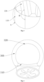
- Embodiments of the present disclosure provide an ablation device, as shown in Figs. 2 and 3 , including a main body structure 110, electrodes, and a plurality of supporting arms 120. All of the supporting arms 120 are spaced apart along a circumference of the main body structure 110.
- the supporting arm 120 is inclined outward relative to the main body structure 110 and includes a contact portion 121.
- the contact portion 121 is of an arcuate structure, and a convex surface of the arcuate structure faces a side of the supporting arm 120 away from the center of the main body structure 110.
- the electrode is arranged on the contact portion 121 and covers at least a part of an outer side wall of the contact portion 121.
- the ablation device is configured to deliver ablation energy at the tissue to be ablated in the human body, and the ablation energy can ablate nerve tissue, thereby achieving the effect of treating a lesion site in the human body.
- the ablation device can be used for ablation of the air tube, heart, aorta, stomach, etc.
- the ablation device is delivered into the air tube through a delivery device, and then the ablation device ablates nerve tissues of the air tube, thereby expanding the air tube and achieving treatment of a pulmonary disease.
- the main body structure 110 provides a supporting force for the supporting arm 120 and can be a tubular structure, a cylindrical structure, or any other structure that provides support for the supporting arm 120.
- the main body structure 110 can be formed by cutting metal material or by weaving woven wires.
- the supporting arm 120 can be made of memory metal material or elastic material and has a certain elastic recovery force after being bent or deformed.
- the supporting arm 120 is welded or integrally connected to the main body structure 110 and is inclined relative to an axial direction of the main body structure 110. Specifically, there define an included angle "a" between a side wall of the supporting arm 120 and an axis of the main body structure 110.
- the included angle "a” is 90° to 175°, for example, the included angle "a” can be 90°, 110°, 120°, 135°, 160°, or 175°.
- a plurality of supporting arms 120 are provided.
- the plurality of supporting arms 120 are provided along the circumference of the main body structure 110 at spaced interval. Two adjacent supporting arms 120 have a spacing distance, and the spacing distance can be equal or different. All of the supporting arms 120 define a divergent structure.
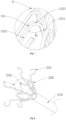
- the cross-section of an air tube 300 has a D-shaped profile, and the air tube 300 includes a smooth muscle 310 and a C-shaped profile 320.
- the supporting arm 120 attaching to the smooth muscle 310 is subjected to a large squeezing force by the air tube 300, thereby causing a large deformation amount of the part of the supporting arm 120 after the force is applied
- the supporting arm 120 attaching to the C-shaped profile is subjected to a small squeezing force by the air tube 300, thereby causing a small deformation amount of the part of the supporting arm 120 after the force is applied.
- the supporting arm 120 includes the contact portion 121.
- the contact portion 121 is located at an end of the supporting arm 120 away from the main body structure 110 and has an arcuate structure, and the convex surface of the arcuate structure faces the side of the supporting arm 120 away from the center of the main body structure 110.
- the air tube 300 includes a plurality of cartilages 330 provided along an axial direction of the air tube300 at spaced intervals, and when the ablation device is released in the air tube 300, the contact portion 121 attaches to a gap 340 between two adjacent cartilages 330.
- an electrode 130 is fixed on the contact portion 121 and covers at least a part of the outer wall of the contact portion 121, and the electrode 130 outputs radio frequency energy to destroy nerves in the tissue of the air tube 300 after being energized.
- the electrode 130 can be connected to the contact portion 121 by welding, bonding, encapsulation, hot-melting, and other processes, and the material of the electrode 130 includes a metal material such as titanium, silver, gold, platinum alloy, palladium, and alloy.
- the number of the electrode 130 is not limited in this embodiment and can be specifically determined according to practical application.
- the electrode 130 includes a strip electrode, a dot electrode, or a mesh electrode.
- the contact portion 121 is made of conductive material to form an electrode.
- the supporting arm 120 is inclined relative to the main body structure 110, allowing all of the supporting arms 120 to define a divergent structure on the whole.
- Fig. 1 when the supporting arms 120 are subjected to the squeezing force from the air tube 300, the deformation degree between two ends of different supporting arms 120 along the axial direction of the main body structure 110 are different.
- the supporting arm 120 attaching to the smooth muscle 310 is subjected to a large pressure, and accordingly, the deformation degree of the supporting arm 120 is also greater, resulting in a greater relative distance between the two ends of the supporting arm 120 in the axial direction of the body structure 110.
- the supporting arm 120 attaching to the C-shaped profile 320 is subjected to a small pressure, and accordingly, the deformation degree of the supporting arm 120 is also less, resulting in a lesser relative distance between the two ends of the supporting arm 120 in the axial direction of the main body structure 110. Therefore, after the supporting arms 120 are released in the air tube 300, the supporting arms 120 are subjected to the squeezing force from the air tube 300, and one end of a part of the supporting arms 120 can cover the gap 340 and attach to the cartilage 330, making it difficult for the electrode 430 to ablate the nerve outside the cartilage 330, affecting the ablation effect of the ablation device on the air tube 300.
- the contact portion 121 forms an arcuate structure, and the convex surface of the arcuate structure faces the side of the supporting arm away from the main body structure 110, causing the contact portions 121 on different supporting arms to at least partially attach to the gap between the cartilages of the air tube 300.
- the electrode 130 is fixed on the contact portion 121 and covers at least a part of the outer wall of the contact portion 121, causing the electrodes 130 on different supporting arms to at least partially attach to the gap between the cartilages of the air tube 300.
- the ablation device form a circumferential continuous ablation energy field on an inner wall of the air tube 300, thus avoiding ablation loss caused by a part of the electrodes 130 not attaching to the inner wall of the air tube 300.
- the end of the contact portion 121 away from the main body structure 110 is provided toward a side of the supporting arm 120 close to the center of the main body structure 110.
- the contact portion 121 includes a first end 1211.
- the first end 1211 is an end of the contact portion 121 pointing at the axial direction of the main body structure 110.
- the first end 1211 is oriented parallel to a radial direction of the main body structure 110.
- the first end 1211 moves toward the inner side of the air tube 300, thereby preventing the first end 1211 from scratching the inner wall of the air tube 300.
- the first end 1211 can also extend toward an inner side of the main body structure 110 so that a centering angle of the contact portion 121 is greater than 180°.
- the first end 1211 is covered with a flexible layer.
- the flexible layer can be made of flexible material with a certain elasticity, such as rubber, silicone, and PEBAX, and it can decrease the frictional force between the first end 1211 and the inner wall of the air tube, thereby preventing the first end 1211 from scratching the inner wall of the air tube.
- an end portion of the first end 1211 can exhibit a spherical or arcuate shape so that the frictional force between the first end 1211 and the inner wall of the air tube can be slowed, thereby preventing the first end 1211 from scratching the inner wall of the air tube.
- the supporting arm 120 includes a bent portion 122.
- bent portion 122 One end of the bent portion 122 is connected to the main body structure 110, and the other end of the bent portion 122 is connected to the contact portion 121.
- the bent portion 122 includes a first connecting arm 1221 and a second connecting arm 1222, one end of the first connecting arm 1221 is connected to the main body structure 110, and one end of the second connecting arm 1222 is connected to the contact portion 121.
- the included angle "b" ranges from 20°-70°, and specifically, can be 20°, 30°, 45°, 50°, 60°, or 70°.
- one end of the bent portion 122 is connected to the body structure 110, and the other end of the bent portion 122 is connected to the contact portion 121 so that the bent portion 122 provide a space for the movement of the contact portion 121 forwarding to the inner side of the air tube 300, and thus the supporting arm 120 adapt to air tubes 300 with different inner diameters.
- an arcuate segment 1223 is provided at a position where the first connecting arm 1221 and the second connecting arm 1222 are connected, and the arcuate segment 1223 is configured to reduce the resistance of the second connecting arm 1222 to bend toward the first connecting arm 1221.
- cooling channel In the embodiment, the main body structure 110 and the supporting arm 120 both have a cavity structure, and the cooling channel is arranged in the interior of the main body structure 110 and the supporting arm 120.
- a cooling medium circulates in the cooling channel and takes away heat from the inner wall of the air tube 300 and the electrode to cool the electrode and the inner wall of the air tube 300.
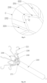
- the embodiment differs from embodiment 1 in that the ablation device further includes an elastic constraining structure 230.
- the elastic constraining structure 230 is connected to two circumferentially adjacent supporting arms 220, and when the supporting arms 220 are squeezed by the air tube, the elastic constraining structure 230 is configured to constrain the amount of displacement of the two adjacent supporting arms 220 to generate relative movement.
- the ablation device includes a loaded state and an expanded state.
- the supporting arm 220 and a main body structure 210 are compressed to be loaded into the delivery device, and the delivery device delivers the ablation device into the air tube 300, at which time the ablation device is in the loaded state; when the ablation device need to be released in the air tube 300, the delivery device releases the ablation device in the air tube 300 to cause ablation of the air tube 300, at which time the ablation device is in the expanded state.
- the supporting arm 220 includes a contact portion 221, when a plurality of the supporting arms 220 are squeezed to be loaded into the delivery device, the contact portions 221 easily catch on each other, resulting in a difficulty in releasing the supporting arms 220 in the air tube 300.
- the elastic constraining structure 230 includes a first constraining member 231 and a second constraining member 232 connected to the first constraining member 231, and the first constraining member 231 and the second constraining member 232 are provided at a predetermined included angle.
- the first constraining member 231 is connected to one of the supporting arms 220, and the second constraining member 232 is connected to the other of the supporting arms 220.
- the first constraining member 231 and the second constraining member 232 are made of elastic material or memory metal material.
- the first constraining member 231 and the second constraining member 232 are integrally connected, and two circumferentially adjacent supporting arms 220 include a first supporting arm 222 and a second supporting arm 223.
- first constraining member 231 is connected to the first supporting arm 222, and one end of the second constraining member 232 is connected to the second supporting arm 223.
- angle “c" between the first constraining member 231 and the second constraining member 232.
- the angle of the included angle “c” ranges from 20°-70°, and specifically, can be 20°, 30°, 45°, 50°, 60°, or 70°.
- first constraining member 231 and the second constraining member 232 when the first constraining member 231 and the second constraining member 232 are squeezed by the supporting arms 220, the first constraining member 231 and the second constraining member 232 move toward each other; when the squeezing force is eliminated, the first constraining member 231 and the second constraining member 232 push the supporting arms 220 to reset.
- first constraining member 231 and the second constraining member 232 at a predetermined included angle, there is a certain movement space between the first constraining member 231 and the second constraining member 232 so that there is still a sufficient movement space between two axially adjacent supporting arms 220, thereby facilitating loading of the ablation device into the delivery device.
- the elastic constraining structure 230 includes a spring-shaped elastic member, and two ends of the elastic member are connected to two circumferentially adjacent supporting arms 220, respectively.
- the elastic member contracts and provides an elastic supporting force for the supporting arms 220, and when the squeezing of the elastic member by the supporting arms 220 is eliminated, the supporting arms 220 are reset under the elastic force of the elastic member.
- the advantage of this arrangement is that when the supporting arms 220 are squeezed by the delivery device, the elastic constraining structure 230 is connected to the two circumferentially adjacent supporting arms 220 so that the elastic constraining structure 230 provide an elastic supporting force for the supporting arms 220.
- the elastic supporting force of the elastic constraining structure 230 on the supporting arms 220 is greater than the squeezing force of the supporting arms 220 on the elastic constraining structure 230 so that the two circumferentially adjacent supporting arms 220 always maintain a certain spacing distance, thereby preventing the contact portions 221 on two circumferentially adjacent supporting arms 220 from catching on each other, and reducing the difficulty of releasing the supporting arms 220 in the air tube 300.
- the ablation device further includes an adjustment assembly 240.
- the adjustment assembly 240 is connected to all of the supporting arms 220 and is configured to take all of the supporting arms 220 to move toward a side close to the center of the body structure 210 or toward a side away from the center of the body structure 210.
- the adjustment assembly 240 includes a pulling member 241 and a plurality of connecting members 242, and all of the connecting members 242 are provided along a circumference of the pulling member 241.
- One end of the connecting member 242 is connected to the pulling member 241, and the other end of the connecting member 242 is connected to the supporting arm 220.
- the pulling member 241 is made of flexible material or rigid material.
- the pulling member 241 is provided along an axial direction of the main body structure 210 and can be provided in parallel with the main body structure 210 or located inside the main body structure 210.
- the pulling member 241 can move along the axial direction of the main body structure 210.
- the connecting member 242 is made of flexible material or elastic material. One end of the connecting member 242 is integrally connected or rotatably connected to the pulling member 241, and the other end of the connecting member 242 is integrally connected or rotatably connected to the supporting arm 220.
- All of the connecting members 242 are provided along the circumference of the pulling member 241 at spaced intervals, and each connecting member 242 is connected to one or more supporting arms 220.
- the pulling member 241 when it is necessary to reduce the opening and closing degree (namely, the included angle "a" between the supporting arm 220 and the main body structure 210) of the supporting arm 220, the pulling member 241 is pulled to move toward a side away from the supporting arm 220, and the pulling member 241 takes the supporting arm 220 to move toward the side close to the center of the main body structure 210 through the connecting member 242, thereby reducing the opening and closing degree of the supporting arm 220; when it is necessary to reset the supporting arm 220, the pulling member 241 is released to eliminate the constraint on the supporting arm 220 by the connecting member 242, and the supporting arm 220 moves toward the side away from the center of the main body structure 210 under the elastic force, thereby achieving the resetting of the supporting arm 220; when it is necessary to increase the opening and closing degree of the supporting arm 220, the pulling member 241 is pushed to move toward a side close to the supporting arm 220, and the pulling member 241 pushes the supporting arm 220 to move toward the side away from
- the adjustment assembly 240 includes a plurality of pull lines, one end of each pull line is connected to the supporting arm 220, and the pull line can move along the axial direction of the main body structure 210.
- the pull line is pulled to make the supporting arm 220 move toward the side close to the center of the main body structure 210.
- the pull line is released to eliminate the constraint on the supporting arm 220, and the supporting arm 220 moves toward the side away from the center of the main body structure 210 under the elastic force, thereby achieving the resetting of the supporting arm 220.
- the advantage of this arrangement is that by connecting the adjustment assembly 240 to all of the supporting arms 220, the adjustment assembly 240 can take all of the supporting arms 220 to move toward the side close to the center of the main body structure 210 or toward the side away from the center of the main body structure 210, thereby achieving adjustment of the opening and closing degrees of the supporting arms 220.
- the opening and closing degree of the supporting arm 220 is reduced to reduce an attachment force between the supporting arm 220 and the inner wall of the air tube 300, thereby facilitating adjustment of the position of the contact portion in the air tube 300.
- a guide hole 211 is arranged on the main body structure 210 and is arranged along the axial direction of the main body structure 210, and the pulling member 241 is inserted into the guide hole 211 and slides in the guide hole 211.
- the axis line of the guide hole 211 coincides with an axis line of the main body structure 210.
- the inner wall of the guide hole 211 is attached to an outer wall of the pulling member 241, and the guide hole 211 extends through two axial ends of the main body structure 210 along the axial direction of the main body structure 210.
- the pulling member 241 is inserted into the guide hole 211, and one end of the pulling member 241 away from the connecting member 242 extends out of the guide hole 211.
- the pulling member 241 is inserted into the guide hole 211 so that the guide hole 211 can define the pulling member 241 at the center of the main body structure 210 to prevent the pulling member 241 from tilting during the movement and causing different forces on different connecting members 242, thereby making the forces on all of the connecting members 242 uniform, and keeping the opening and closing degrees of all of the supporting arms 220 consistent during the movement of the supporting arms 220 driven by the pulling member 241.
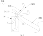
- the connecting member 242 includes a first bent portion 2421 and a second bent portion 2422.
- the first bent portion 2421 is bent from a side of the connecting member 242 away from the main body structure 210 to a side close to the main body structure 210
- the second bent portion 2422 is bent from the side of the connecting member 242 close to the main body structure 210 to the side away from the main body structure 210.
- the connecting member 242 includes a third connecting arm 2423, a fourth connecting arm 2424, and a fifth connecting arm 2425 connected sequentially.
- the two ends of the fourth connecting arm 2424 are connected to the third connecting arm 2423 and the fifth connecting arm 2425, respectively.
- the third connecting arm 2423 is connected to the pulling member 241, and the fifth connecting arm 2425 is connected to the supporting arm 220.
- There is an included angle between the third connecting arm 2423 and the fourth connecting arm 2424, and an opening of the included angle "d" is arranged toward the main body structure 210 to form the first bent portion 2421.
- the angle of the included angle "d” ranges from 10°-35°, and specifically, is 10°, 15°, 20°, 30° and 35°.
- the angle of the included angle “e” ranges from 15-90°, and specifically, is 15°, 30°, 45°, 60°, 70°, or 90°.
Landscapes
- Health & Medical Sciences (AREA)
- Life Sciences & Earth Sciences (AREA)
- Surgery (AREA)
- Engineering & Computer Science (AREA)
- Plasma & Fusion (AREA)
- General Health & Medical Sciences (AREA)
- Otolaryngology (AREA)
- Physics & Mathematics (AREA)
- Veterinary Medicine (AREA)
- Biomedical Technology (AREA)
- Heart & Thoracic Surgery (AREA)
- Medical Informatics (AREA)
- Molecular Biology (AREA)
- Animal Behavior & Ethology (AREA)
- Nuclear Medicine, Radiotherapy & Molecular Imaging (AREA)
- Public Health (AREA)
- Cardiology (AREA)
- Surgical Instruments (AREA)
Applications Claiming Priority (2)
| Application Number | Priority Date | Filing Date | Title |
|---|---|---|---|
| CN202123451073.7U CN217611360U (zh) | 2021-12-31 | 2021-12-31 | 消融装置 |
| PCT/CN2022/141951 WO2023125416A1 (zh) | 2021-12-31 | 2022-12-26 | 消融装置 |
Publications (2)
| Publication Number | Publication Date |
|---|---|
| EP4458299A1 true EP4458299A1 (de) | 2024-11-06 |
| EP4458299A4 EP4458299A4 (de) | 2025-12-17 |
Family
ID=83641644
Family Applications (1)
| Application Number | Title | Priority Date | Filing Date |
|---|---|---|---|
| EP22914670.9A Pending EP4458299A4 (de) | 2021-12-31 | 2022-12-26 | Ablationsvorrichtung |
Country Status (4)
| Country | Link |
|---|---|
| US (1) | US20250114139A1 (de) |
| EP (1) | EP4458299A4 (de) |
| CN (1) | CN217611360U (de) |
| WO (1) | WO2023125416A1 (de) |
Families Citing this family (1)
| Publication number | Priority date | Publication date | Assignee | Title |
|---|---|---|---|---|
| CN217611360U (zh) * | 2021-12-31 | 2022-10-21 | 深圳市先健呼吸科技有限公司 | 消融装置 |
Family Cites Families (9)
| Publication number | Priority date | Publication date | Assignee | Title |
|---|---|---|---|---|
| US7198635B2 (en) * | 2000-10-17 | 2007-04-03 | Asthmatx, Inc. | Modification of airways by application of energy |
| US6669693B2 (en) * | 2001-11-13 | 2003-12-30 | Mayo Foundation For Medical Education And Research | Tissue ablation device and methods of using |
| WO2013166292A1 (en) * | 2012-05-02 | 2013-11-07 | The Charlotte-Mecklenburg Hospital Authority D/ B/ A Carolinas Healthcare System | Devices, systems, and methods for treating cardiac arrhythmias |
| US10537286B2 (en) * | 2013-01-08 | 2020-01-21 | Biosense Webster (Israel) Ltd. | Catheter with multiple spines of different lengths arranged in one or more distal assemblies |
| CN205019161U (zh) * | 2015-08-12 | 2016-02-10 | 上海魅丽纬叶医疗科技有限公司 | 具有贴壁调节丝的波纹型射频消融导管及其设备 |
| CN109561929A (zh) * | 2016-06-06 | 2019-04-02 | 纽乌罗有限公司 | 用于远场双极消融的装置 |
| US10813590B2 (en) * | 2016-10-28 | 2020-10-27 | Ablacon Inc. | Electrophysiological mapping catheter |
| CN114404034A (zh) * | 2021-02-09 | 2022-04-29 | 杭州德诺电生理医疗科技有限公司 | 消融装置 |
| CN217611360U (zh) * | 2021-12-31 | 2022-10-21 | 深圳市先健呼吸科技有限公司 | 消融装置 |
-
2021
- 2021-12-31 CN CN202123451073.7U patent/CN217611360U/zh active Active
-
2022
- 2022-12-26 US US18/725,022 patent/US20250114139A1/en active Pending
- 2022-12-26 EP EP22914670.9A patent/EP4458299A4/de active Pending
- 2022-12-26 WO PCT/CN2022/141951 patent/WO2023125416A1/zh not_active Ceased
Also Published As
| Publication number | Publication date |
|---|---|
| EP4458299A4 (de) | 2025-12-17 |
| US20250114139A1 (en) | 2025-04-10 |
| CN217611360U (zh) | 2022-10-21 |
| WO2023125416A1 (zh) | 2023-07-06 |
Similar Documents
| Publication | Publication Date | Title |
|---|---|---|
| US10500049B2 (en) | Flexible radio-opaque protrusions for revealing the position of a constricting cord or annulus ring prior to installation onto a cardiac valve annulus | |
| US7815591B2 (en) | Atraumatic gastrointestinal anchor | |
| KR20230154061A (ko) | 혈전 제거 장치 및 방법 | |
| AU2018253740B2 (en) | Braid expansion ring with markers | |
| EP3275391A1 (de) | Geräte zur energieabgabe | |
| CN114617603B (zh) | 封堵装置 | |
| EP4458299A1 (de) | Ablationsvorrichtung | |
| CN112656461A (zh) | 封堵装置 | |
| EP4260817A1 (de) | Verschlussvorrichtung | |
| CN120154387B (zh) | 取栓支架 | |
| US9610179B2 (en) | Atraumatic stent crowns | |
| CN115998483B (zh) | 管腔支架及支架系统 | |
| EP4458301A1 (de) | Nervenablationsvorrichtung | |
| US20230009461A1 (en) | Medical device | |
| US20230021193A1 (en) | Medical device and method for manufacturing expansion body | |
| KR20230147763A (ko) | 혈전 제거 장치 및 방법 | |
| CN116211562B (zh) | 一种凸点支架 | |
| CN215841153U (zh) | 不阻断腔内流体的管腔内递药装置 | |
| CN115813461B (zh) | 医用封堵装置 | |
| CN119327023B (zh) | 锚固装置及血泵系统 | |
| US20250295900A1 (en) | Implantable medical device and delivery device | |
| JP2024081198A (ja) | ステント及び送達デバイス | |
| JP2024081199A (ja) | 埋め込み式医療デバイス及び送達デバイス | |
| CN112843445A (zh) | 不阻断腔内流体的管腔内递药装置 | |
| CN121465668A (zh) | 输送装置 |
Legal Events
| Date | Code | Title | Description |
|---|---|---|---|
| STAA | Information on the status of an ep patent application or granted ep patent |
Free format text: STATUS: THE INTERNATIONAL PUBLICATION HAS BEEN MADE |
|
| PUAI | Public reference made under article 153(3) epc to a published international application that has entered the european phase |
Free format text: ORIGINAL CODE: 0009012 |
|
| STAA | Information on the status of an ep patent application or granted ep patent |
Free format text: STATUS: REQUEST FOR EXAMINATION WAS MADE |
|
| 17P | Request for examination filed |
Effective date: 20240730 |
|
| AK | Designated contracting states |
Kind code of ref document: A1 Designated state(s): AL AT BE BG CH CY CZ DE DK EE ES FI FR GB GR HR HU IE IS IT LI LT LU LV MC ME MK MT NL NO PL PT RO RS SE SI SK SM TR |
|
| DAV | Request for validation of the european patent (deleted) | ||
| DAX | Request for extension of the european patent (deleted) | ||
| A4 | Supplementary search report drawn up and despatched |
Effective date: 20251114 |
|
| RIC1 | Information provided on ipc code assigned before grant |
Ipc: A61B 18/12 20060101AFI20251110BHEP Ipc: A61B 18/14 20060101ALI20251110BHEP Ipc: A61B 18/00 20060101ALN20251110BHEP |