EP4458255A1 - Sighting device and measurement device - Google Patents
Sighting device and measurement device Download PDFInfo
- Publication number
- EP4458255A1 EP4458255A1 EP23759582.2A EP23759582A EP4458255A1 EP 4458255 A1 EP4458255 A1 EP 4458255A1 EP 23759582 A EP23759582 A EP 23759582A EP 4458255 A1 EP4458255 A1 EP 4458255A1
- Authority
- EP
- European Patent Office
- Prior art keywords
- measuring apparatus
- antenna
- sighting device
- viewing range
- indicator
- Prior art date
- Legal status (The legal status is an assumption and is not a legal conclusion. Google has not performed a legal analysis and makes no representation as to the accuracy of the status listed.)
- Pending
Links
Images






Classifications
-
- A—HUMAN NECESSITIES
- A61—MEDICAL OR VETERINARY SCIENCE; HYGIENE
- A61B—DIAGNOSIS; SURGERY; IDENTIFICATION
- A61B5/00—Measuring for diagnostic purposes; Identification of persons
-
- G—PHYSICS
- G01—MEASURING; TESTING
- G01B—MEASURING LENGTH, THICKNESS OR SIMILAR LINEAR DIMENSIONS; MEASURING ANGLES; MEASURING AREAS; MEASURING IRREGULARITIES OF SURFACES OR CONTOURS
- G01B11/00—Measuring arrangements characterised by the use of optical techniques
- G01B11/26—Measuring arrangements characterised by the use of optical techniques for measuring angles or tapers; for testing the alignment of axes
- G01B11/27—Measuring arrangements characterised by the use of optical techniques for measuring angles or tapers; for testing the alignment of axes for testing the alignment of axes
-
- A—HUMAN NECESSITIES
- A61—MEDICAL OR VETERINARY SCIENCE; HYGIENE
- A61B—DIAGNOSIS; SURGERY; IDENTIFICATION
- A61B5/00—Measuring for diagnostic purposes; Identification of persons
- A61B5/0002—Remote monitoring of patients using telemetry, e.g. transmission of vital signals via a communication network
-
- A—HUMAN NECESSITIES
- A61—MEDICAL OR VETERINARY SCIENCE; HYGIENE
- A61B—DIAGNOSIS; SURGERY; IDENTIFICATION
- A61B5/00—Measuring for diagnostic purposes; Identification of persons
- A61B5/02—Detecting, measuring or recording for evaluating the cardiovascular system, e.g. pulse, heart rate, blood pressure or blood flow
-
- A—HUMAN NECESSITIES
- A61—MEDICAL OR VETERINARY SCIENCE; HYGIENE
- A61B—DIAGNOSIS; SURGERY; IDENTIFICATION
- A61B5/00—Measuring for diagnostic purposes; Identification of persons
- A61B5/02—Detecting, measuring or recording for evaluating the cardiovascular system, e.g. pulse, heart rate, blood pressure or blood flow
- A61B5/024—Measuring pulse rate or heart rate
- A61B5/02416—Measuring pulse rate or heart rate using photoplethysmograph signals, e.g. generated by infrared radiation
-
- A—HUMAN NECESSITIES
- A61—MEDICAL OR VETERINARY SCIENCE; HYGIENE
- A61B—DIAGNOSIS; SURGERY; IDENTIFICATION
- A61B5/00—Measuring for diagnostic purposes; Identification of persons
- A61B5/02—Detecting, measuring or recording for evaluating the cardiovascular system, e.g. pulse, heart rate, blood pressure or blood flow
- A61B5/024—Measuring pulse rate or heart rate
- A61B5/02416—Measuring pulse rate or heart rate using photoplethysmograph signals, e.g. generated by infrared radiation
- A61B5/02427—Details of sensor
-
- A—HUMAN NECESSITIES
- A61—MEDICAL OR VETERINARY SCIENCE; HYGIENE
- A61B—DIAGNOSIS; SURGERY; IDENTIFICATION
- A61B5/00—Measuring for diagnostic purposes; Identification of persons
- A61B5/02—Detecting, measuring or recording for evaluating the cardiovascular system, e.g. pulse, heart rate, blood pressure or blood flow
- A61B5/024—Measuring pulse rate or heart rate
- A61B5/02438—Measuring pulse rate or heart rate with portable devices, e.g. worn by the patient
-
- A—HUMAN NECESSITIES
- A61—MEDICAL OR VETERINARY SCIENCE; HYGIENE
- A61B—DIAGNOSIS; SURGERY; IDENTIFICATION
- A61B5/00—Measuring for diagnostic purposes; Identification of persons
- A61B5/05—Detecting, measuring or recording for diagnosis by means of electric currents or magnetic fields; Measuring using microwaves or radio waves
- A61B5/0507—Detecting, measuring or recording for diagnosis by means of electric currents or magnetic fields; Measuring using microwaves or radio waves using microwaves or terahertz waves
-
- A—HUMAN NECESSITIES
- A61—MEDICAL OR VETERINARY SCIENCE; HYGIENE
- A61B—DIAGNOSIS; SURGERY; IDENTIFICATION
- A61B5/00—Measuring for diagnostic purposes; Identification of persons
- A61B5/145—Measuring characteristics of blood in vivo, e.g. gas concentration or pH-value ; Measuring characteristics of body fluids or tissues, e.g. interstitial fluid or cerebral tissue
- A61B5/1455—Measuring characteristics of blood in vivo, e.g. gas concentration or pH-value ; Measuring characteristics of body fluids or tissues, e.g. interstitial fluid or cerebral tissue using optical sensors, e.g. spectral photometrical oximeters
-
- A—HUMAN NECESSITIES
- A61—MEDICAL OR VETERINARY SCIENCE; HYGIENE
- A61B—DIAGNOSIS; SURGERY; IDENTIFICATION
- A61B5/00—Measuring for diagnostic purposes; Identification of persons
- A61B5/68—Arrangements of detecting, measuring or recording means, e.g. sensors, in relation to patient
- A61B5/6801—Arrangements of detecting, measuring or recording means, e.g. sensors, in relation to patient specially adapted to be attached to or worn on the body surface
- A61B5/6802—Sensor mounted on worn items
- A61B5/681—Wristwatch-type devices
-
- G—PHYSICS
- G01—MEASURING; TESTING
- G01S—RADIO DIRECTION-FINDING; RADIO NAVIGATION; DETERMINING DISTANCE OR VELOCITY BY USE OF RADIO WAVES; LOCATING OR PRESENCE-DETECTING BY USE OF THE REFLECTION OR RERADIATION OF RADIO WAVES; ANALOGOUS ARRANGEMENTS USING OTHER WAVES
- G01S13/00—Systems using the reflection or reradiation of radio waves, e.g. radar systems; Analogous systems using reflection or reradiation of waves whose nature or wavelength is irrelevant or unspecified
- G01S13/88—Radar or analogous systems specially adapted for specific applications
Definitions
- the present invention relates to a technique for improving the measurement accuracy of biological information.
- Patent Document 1 Japanese Unexamined Patent Publication No. 2017-029452
- the present invention has been made in view of the above circumstances, and provides a technique for improving the measurement accuracy of biological information of a person to be measured.
- the present invention adopts the following configurations.
- One aspect of the present invention is a sighting device used in a measuring apparatus including a signal detector that detects a signal related to biological information reflected from a person to be measured, the sighting device including: a visible indicator; and a viewing range specifier that specifies a viewing range of the indicator.
- a relative position between the indicator and the viewing range specifier is determined such that the viewing range of the indicator specified by the viewing range specifier forms an area included in a detection range of the signal by the signal detector.
- the indicator may be formed on an inner surface of a recess formed in an exterior member of the measuring apparatus, and the viewing range specifier is an opening of the recess.
- the sighting device may further include two walls facing each other.
- the indicator may be formed on one wall of the two walls, and the viewing range specifier may be a window portion penetrating another wall of the two walls.
- the viewing range specifier may be two rod members extending from an outer surface of an exterior member of the measuring apparatus, the two rod members being disposed at positions for specifying a viewing range of the indicator in at least one of an azimuth angle direction or an elevation angle direction as viewed from the signal detector.
- the viewing range specifier may be two indicators visible from the outside of the measuring apparatus, the two indicators being disposed at positions for specifying a viewing range of the indicator in an azimuth angle direction or an elevation angle direction as viewed from the signal detector.
- a user of the measuring apparatus or a person to be measured can specify the signal detection range of the signal detector with a simple configuration.
- one aspect of the present invention is a measuring apparatus including the sighting device and the signal detector.
- the measuring apparatus may further include an adjuster configured to change a direction of the sighting device in at least one of an azimuth angle direction or an elevation angle direction as viewed from the signal detector.
- Fig. 1 is a view schematically illustrating an example of use of a measuring apparatus 100 to which the present invention is applied.
- the measuring apparatus 100 includes an antenna 102 that transmits and receives a signal for acquiring biological information to and from a person to be measured in a casing 101 that is a rectangular parallelepiped exterior member.
- the measuring apparatus 100 performs so-called non-contact biological information sensing.
- a signal transmitted by the antenna 102 passes through a front surface 101a of the casing 101, reaches the person to be measured, is reflected from the person to be measured, and is detected by the antenna 102 that is a signal detector.
- Examples of the frequency of the signal transmitted from the antenna 102 to the person to be measured include frequencies in a frequency band of 30 GHz to 300 GHz used for a millimeter-wave radar, but frequencies in other frequency bands such as light, radio waves, sound waves, and ultrasonic waves may be adopted.
- the shape of the antenna 102 is schematically illustrated as an ellipse in Fig. 1 , various shapes may be adopted as the shape of the antenna 102.
- the measuring apparatus 100 includes the antenna 102, but a signal detector may be adopted in place of the antenna 102 in the measuring apparatus 100 according to the frequency of the signal to be used.
- a signal transmission method to be used may be a continuous wave such as frequency modulated continuous wave (FM-CW) or CW, or may be an intermittent wave.
- the antenna 102 may be formed of a transmission antenna and a reception antenna separately.
- the measuring apparatus 100 has a sighting device 200 disposed on an upper surface 101b of the casing 101 for a user of the measuring apparatus 100, the person to be measured, or others to confirm the signal detection range (signal transmission range) of the antenna 102.
- the sighting device 200 is fixed to the upper surface 101b by a mounting member (not illustrated).
- the sighting device 200 includes a main body 201, and the main body 201 is provided with a visible mark 202 and a window portion 203.
- the material of the sighting device 200 is not particularly limited, but more preferably, the sighting device 200 is formed of a material having a low relative permittivity, such as plastic, which does not interfere with signals transmitted and received by the antenna 102 as much as possible.
- the size of the window portion 203 is determined based on the directivity of the antenna 102 such that a position is within the signal detection range of the antenna 102 as long as the mark 202 is visible through the window portion 203 from that position.
- the relationship between the range in which the mark 202 is visible through the window portion 203 and the signal detection range of the antenna 102 will be described later.
- the user of the measuring apparatus 100 or the person to be measured can specify the signal detection range of the antenna 102 with a simple configuration. This can prevent the person to be measured from being out of the signal detection range of the antenna 102, improving the measurement accuracy of the measuring apparatus 100.
- XYZ axes orthogonal to each other are determined.
- the casing 101 is a rectangular parallelepiped exterior member, and XYZ axes are determined such that a YZ plane is a plane parallel to the front surface 101a (and the back surface) of the casing 101, an XY plane is a plane parallel to the upper surface 101b (and the bottom surface) of the casing 101, and an XZ plane is a plane parallel to a side surface 101c of the casing 101.
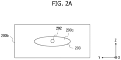
- Fig. 2A illustrates a front view of the sighting device 200 fixed to the measuring apparatus 100
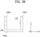
- Fig. 2B illustrates a side view of the sighting device 200
- the sighting device 200 includes a flat plate-shaped base 200a parallel to the XY plane and two flat plate-shaped walls 200b, 200c extending from the base 200a in a direction parallel to the Z axis.
- the walls 200b, 200c are provided at separate positions so as to face each other.
- the wall 200b is provided with the window portion 203 penetrating the wall 200b in the X-axis direction, and the mark 202 is provided on the wall 200b side of the wall 200c.
- the mark 202 is formed using various paints as long as the user of the measuring apparatus 100 or the person to be measured can view the mark 200.
- the mark 202 may be formed using a known technique, such as a projection or a recess formed on the surface of the wall 200c, a light-emitting diode (LED) lamp provided on the wall 200c, or a seal attached to the wall 200c, as long as the mark 202 are visible.
- a known technique such as a projection or a recess formed on the surface of the wall 200c, a light-emitting diode (LED) lamp provided on the wall 200c, or a seal attached to the wall 200c, as long as the mark 202 are visible.
- LED light-emitting diode
- the window portion 203 is an elliptical window portion as viewed in the X-axis direction.
- the mark 202 is formed on the wall 200c at a position where the mark 202 can be viewed so as to overlap with the intersection of the major and minor axes of the ellipse of the window portion 203 when the window portion 203 is viewed in the X-axis direction. Therefore, when the sighting device 200 is viewed in the X-axis direction from the front surface 101a side of the casing 101 of the measuring apparatus 100, the mark 202 is visible through the window portion 203.
- the sighting device 200 is divided into the base 200a and the walls 200b, 200c for the sake of description, but the base 200a and the walls 200b, 200c may be integrally formed as illustrated in Fig. 1 .
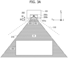
- Fig. 3A is a view schematically illustrating a range 210 in which the mark 202 is visible through the window portion 203 and a signal detection range 110 of the antenna 102 in a top view of the casing 101 of the measuring apparatus 100.
- Fig. 3B is a view schematically illustrating the range 210 in which the mark 202 is visible through the window portion 203 and the signal detection range 110 of the antenna 102 in a side view of the casing 101 of the measuring apparatus 100.
- the signal detection range 110 of the antenna 102 is determined based on the directivity of the antenna 102 with reference to a center 103 of the antenna 102 that receives a signal from the person to be measured.
- the antenna 102 and the mark 202 are arranged such that the center 103 of the antenna 102 (in this example, the intersection of the major and minor axes of the ellipse of the antenna 102) and the mark 202 substantially overlap in the top view of the casing 101 of the measuring apparatus 100.
- Fig. 3B it is assumed that the antenna 102 and the mark 202 are arranged such that the center 103 of the antenna 102 and the mark 202 are aligned vertically in the side view of the casing 101 of the measuring apparatus 100.
- the range 210 in which the mark 202 is visible through the window portion 203 is formed on the front surface 101a side of the casing 101.
- the signal detection range 110 of the antenna 102 is formed on the front surface 101a side of the casing 101.
- an area A is formed where at least a part of the range 210, in which the mark 202 is visible, is included in the signal detection range 110. Therefore, when the person to be measured is within that area A, a signal can be detected by the antenna 102. For example, as illustrated in Figs.
- the signal detection range 110 of the antenna 102 does not overlap with the range 210 in which the mark 202 is visible through the window portion 203 in the range of a distance D1 from the front surface 101a of the casing 101.
- the signal detection range 110 of the antenna 102 and the range 210 in which the mark 202 is visible through the window portion 203 do not overlap.
- the relative position between the mark 202 and the window portion 203 is a position at which the mark 202 can be viewed so as to overlap with the intersection of the major and minor axes of the ellipse of the window portion 203 when the window portion 203 is viewed in the X-axis direction.
- the relative position between the mark 202 and the window portion 203 may be appropriately changed according to the directivity of the antenna 102.
- the sighting device 200 is configured separately from the measuring apparatus 100.
- the sighting device can also be configured integrally with the measuring apparatus.
- Fig. 4 illustrates an example of a measuring apparatus 1100 according to the embodiment.
- an antenna 1102 is disposed in a casing 1101 that is a rectangular parallelepiped exterior member.
- a recess 1204 where a part of a front surface 1101a is recessed in the X-axis direction, is formed in the front surface 1101a of the casing 1101.
- the recess 1204 includes an elliptical opening 1203 similar to the window portion 203 of the first embodiment and a bottom surface 1204a having a shape corresponding to the shape of the opening 1203.
- a mark 1202 corresponding to the mark 202 of the first embodiment is formed on a bottom 1204a that is a part of the inner surface of the recess 1204.
- the antenna 1102 and the mark 1202 are arranged such that a center 1103 of the antenna 1102 and the mark 1202 substantially overlap in a top view of the casing 1101 of the measuring apparatus 1100, and such that the center 103 of the antenna 102 and the mark 202 are aligned vertically in a side view of the casing 1101 of the measuring apparatus 1100.
- the opening 1203 of the recess 1204 corresponds to the window portion 203 of the first embodiment
- the mark 1202 of the recess 1204 corresponds to the mark 202 of the first embodiment
- the recess 1204 including the opening 1203 and the mark 1202 functions as a sighting device corresponding to the sighting device 200 of the first embodiment.
- the mark 1202 can be disposed at a position closer to the center of the antenna 1102 compared to the first embodiment.
- the area where the range in which the mark is visible and the signal detection range of the antenna overlap is larger than in the case of the first embodiment.
- the recess 1204 is formed as an elliptic columnar cavity, but the inner surface shape of the recess 1204 is not limited thereto.
- the inner surface of the recess 1204 may be formed of a paraboloid surface, and the mark 1202 may be provided on a part of the paraboloid surface.
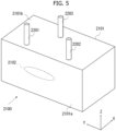
- FIG. 5 illustrates an example of the measuring apparatus 2100 according to the present modification.
- an antenna 2102 is disposed in a casing 2101 that is a rectangular parallelepiped exterior member.
- a signal transmitted by the antenna 2102 passes through a front surface 2101a of the casing 2101, reaches a person to be measured, is reflected by the person to be measured, and is detected by the antenna 2102.
- three columnar rod members 2201, 2202, 2203 extending in the Z-axis direction from the upper surface 2101b are provided.
- the rod members 2201 to 2203 may be removably provided on the casing 2101, or may be integrally provided with the casing 2101.
- two rod members 2201, 2202 of the three rod members 2201 to 2203 are disposed closer to the front surface 2101a than the remaining rod member 2203.
- the three rod members 2201 to 2203 function as a sighting device corresponding to the sighting device 200 of the first embodiment.
- the rod member 2203 is disposed at a position substantially overlapping with the center of the antenna 2102, similarly to the marks 202, 1202 described above. Further, in the top view of the casing 2101, the positions of the rod members 2201, 2202 are set such that the range in which the rod member 2203 is visible between the rod members 2201 and 2202 when viewed in the X-axis direction from the front surface 2101a side of the casing 2101 is included in the signal detection range of the antenna 2102.
- the rod members 2201, 2202 determine the viewing range of the rod member 2203 to specify the position as being within the signal detection range of the antenna 2102 in the azimuth angle (the angle of rotation about the Z axis in the XY plane) direction of the antenna 2102.
- the measurement accuracy of the measuring apparatus can be expected to be improved by placing the person to be measured within the signal detection range of the antenna, using a simpler configuration than the sighting device 200 of the first embodiment.
- FIG. 6 illustrates an example of the measuring apparatus 3100 according to the present modification.
- an antenna 3102 is disposed in a casing 3101 that is a rectangular parallelepiped exterior member.
- a signal transmitted by the antenna 3102 passes through a front surface 3101a of the casing 3101, reaches a person to be measured, is reflected by the person to be measured, and is detected by the antenna 3102.
- three columnar rod members 3201, 3202, 3203 extending in the Y-axis direction from the side surface 3101c are provided.
- the rod members 3201 to 3203 may be removably provided on the casing 3101, or may be integrally provided with the casing 3101.
- two rod members 3201, 3202 of the three rod members 3201 to 3203 are disposed closer to the front surface 3101a than the remaining rod member 3203.
- the three rod members 3201 to 3203 function as a sighting device corresponding to the sighting device 200 of the first embodiment.
- the rod member 3203 is disposed at a position substantially overlapping with the center of the antenna 3102.
- the positions of the rod members 3201, 3202 are set such that the range in which the rod member 3203 is visible between the rod members 3201 and 3202 when viewed in the X-axis direction from the front surface 3101a side of the casing 3101 is included in the signal detection range of the antenna 3102.
- the rod members 3201, 3202 determine the viewing range of the rod member 3203 to specify the position as being within the signal detection range of the antenna 3102 in the elevation angle (the angle of rotation about the Y axis in the XZ plane) direction of the antenna 3102.
- the measurement accuracy of the measuring apparatus can be expected to be improved by placing the person to be measured within the signal detection range of the antenna, using a simpler configuration than the sighting device 200 of the first embodiment.
- FIG. 7 illustrates an example of the measuring apparatus 4100 according to the present modification.
- an antenna 4102 is disposed in a casing 4101 that is a rectangular parallelepiped exterior member.
- a signal transmitted by the antenna 4102 passes through a front surface 4101a of the casing 4101, reaches a person to be measured, is reflected by the person to be measured, and is detected by the antenna 4102.
- two marks 4201, 4202 are provided on the front surface 4101a of the casing 4101.
- the marks 4201, 4202 are provided near the upper end of the front surface 4101a.
- a columnar rod member 4203 extending in the Z-axis direction from the upper surface 4101b is provided on an upper surface 4101b of the casing 4101.
- the marks 4201, 4202 are indicators in place of the rod members 2201, 2202 of Modification 1, and are indicators that define virtual boundary lines 4211, 4212 in the azimuth angle (the angle of rotation about the Z axis in the XY plane) direction of the antenna 4102 when the rod member 4203 is viewed to confirm the signal detection range of the antenna 4120.
- the virtual boundary lines 4211, 4212 can be regarded as lines extending in the Z-axis direction through the marks 4201, 4202. Note that any shape may be adopted as the shapes of the marks 4201, 4202 as long as the marks 4201, 4202 are visible. In the present modification, the two marks 4201, 4202 and the rod member 4203 function as a sighting device corresponding to the sighting device 200 of the first embodiment.
- the rod member 4203 is disposed at a position substantially overlapping with the center of the antenna 4102, similarly to the rod member 2203 described above. Further, in the top view of the casing 4101, the positions of the marks 4201, 4202 are set such that the range in which the rod member 4203 is visible between the virtual boundary lines 4211 and 4212, defined by the marks 4201, 4202, when viewed in the X-axis direction from the front surface 4101a side of the casing 4101 is included in the signal detection range in the azimuth angle direction of the antenna 4102.
- the virtual boundary lines 4211, 4212 determine the viewing range of the rod member 4203 to specify the position as being within the signal detection range of the antenna 4102 in the azimuth angle (the angle of rotation about the Z axis in the XY plane) direction of the antenna 4102. Accordingly, in the present modification as well, similarly to Modification 1, on the front surface 4101a side of the casing 4101, it is possible to form an area where the range in which the rod member 4203 is visible between the virtual boundary lines 4211 and 4212, defined by the marks 4201, 4202, is included in the signal detection range of the antenna 4102. Therefore, when the person to be measured is within that area, the signal can be detected by the antenna 4102.
- the measurement accuracy of the measuring apparatus can be expected to be improved by placing the person to be measured within the signal detection range of the antenna, using a simpler configuration than the sighting device 200 of the first embodiment.
- FIG. 8 illustrates an example of the measuring apparatus 5100 according to the present modification.
- an antenna 5102 is disposed in a casing 5101 that is a rectangular parallelepiped exterior member.
- a signal transmitted by the antenna 5102 passes through a front surface 5101a of the casing 5101, reaches a person to be measured, is reflected by the person to be measured, and is detected by the antenna 5102.
- Two marks 5201, 5202 are provided on the front surface 5101a of the casing 5101.
- the marks 5201, 5202 are provided near one end (the right end in the drawing) of the front surface 5101a in the horizontal direction.
- a columnar rod member 5203 extending in the Y-axis direction from the side surface 5101c is provided on a side surface 5101c of the casing 5101.
- the marks 5201, 5202 are indicators similar to the marks 4201, 4202 of Modification 3, and are indicators that define virtual boundary lines 5211, 5212 in the elevation angle (the angle of rotation about the Y axis in the XZ plane) direction when the rod member 5203 is viewed to confirm the signal detection range of the antenna 5102.
- the virtual boundary lines 5211, 5212 can be regarded as lines extending in the Y-axis direction through the marks 5201, 5202. Note that any shape may be adopted as the shapes of the marks 5201, 5202 as long as the marks 5201, 5202 are visible. In the present modification, the two marks 5201, 5202 and the rod member 5203 function as a sighting device corresponding to the sighting device 200 of the first embodiment.
- the rod member 5203 is disposed at a position substantially overlapping with the center of the antenna 5102, similarly to the rod member 3203 described above.
- the positions of the marks 5201, 5202 are set such that the range in which the rod member 5203 is visible between the virtual boundary lines 5211 and 5212, defined by the marks 5201, 5202, when viewed in the X-axis direction from the front surface 5101a side of the casing 5101 is included in the signal detection range of the antenna 5102.
- the virtual boundary lines 5211, 5212, defined by the marks 5201, 4502 determine the viewing range of the rod member 5203 to specify the position as being within the signal detection range of the antenna 5102 in the elevation angle (the angle of rotation about the Y axis in the XZ plane) direction of the antenna 5102. Accordingly, in the present modification as well, similarly to Modification 3, on the front surface 5101a side of the casing 5101, it is possible to form an area where the range in which the rod member 5203 is visible between the virtual boundary lines 5211 and 5212, defined by the marks 5201, 5202, is included in the signal detection range of the antenna 5102. Therefore, when the person to be measured is within that area, the signal can be detected by the antenna 5102.
- the measurement accuracy of the measuring apparatus can be expected to be improved by placing the person to be measured within the signal detection range of the antenna, using a simpler configuration than the sighting device 200 of the first embodiment.
- FIG. 9 illustrates an example of the measuring apparatus 6100 according to the present modification.
- an antenna 6102 is disposed in a casing 6101 that is a rectangular parallelepiped exterior member.
- a signal transmitted by the antenna 6102 passes through a front surface 6101a of the casing 6101, reaches a person to be measured, is reflected by the person to be measured, and is detected by the antenna 6102.
- the walls 200b, 200c constituting the sighting device 200 of the first embodiment are configured as separate walls 6210, 6220.
- a window portion 6203 corresponding to the window portion 203 of the first embodiment is formed in the wall 6210, and a mark 6202 corresponding to the mark 202 of the first embodiment is formed of the wall 6220.
- the walls 6210, 6220 are fixed to an upper surface 6101b of the casing 6101 using respective mounting member (not illustrated). Note that the mounting member can be implemented using a known technique, and therefore a detailed description thereof will be omitted.
- the two walls 6210, 6220 function as a sighting device corresponding to the sighting device 200 of the first embodiment.
- the relationship among the mark 6202, the window portion 6203, and the center of the antenna 6102 corresponds to the relationship among the mark 202, the window portion 203, and the center of the antenna 102 in the first embodiment.
- an area is formed where the range in which the mark 6202 is visible through the window portion 6203 is included in the signal detection range of the antenna 6102. Therefore, when the person to be measured is within that area, the signal can be detected by the antenna 6102.
- the measurement accuracy of the measuring apparatus can be expected to be improved by placing the person to be measured within the signal detection range of the antenna, using a configuration similar to the sighting device 200 of the first embodiment.
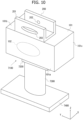
- FIG. 10 illustrates an example of the measuring apparatus 7100 according to the present modification.
- the measuring apparatus 7100 has a configuration similar to the measuring apparatus 100 and the sighting device 200 in the first embodiment. Therefore, in the following description, components similar to those of the first embodiment are denoted by the same reference numerals, and a detailed description thereof will be omitted.
- the measuring apparatus 7100 includes a flat plate-shaped pedestal 7400 and a cylindrical support portion 7300 for supporting the casing 101 to which the sighting device 200 is fixed. Moreover, the measuring apparatus 7100 includes an adjuster 7200 for changing the orientation of the casing 101, the orientation of the sighting device 200 fixed to the casing 101 in the azimuth angle (the angle of rotation about the Z axis in the XY plane) direction and the elevation angle (the angle of rotation about the Y axis in the XZ plane) direction of the antenna 102. As an example, the adjuster 7200 rotates the casing 101 about the Y axis and the Z axis.
- the rotation mechanism of the adjuster 7200 can be implemented by using a known technique, and therefore a detailed description thereof will be omitted here.
- the adjuster 7200 may be configured to change the orientation of the sighting device 200 in at least one of the azimuth angle direction or the elevation angle direction of the antenna 102.
- the measurement accuracy of the measuring apparatus can be expected to be improved by changing the signal detection range of the antenna according to the use environment of the measuring apparatus 7100 and by placing the person to be measured within the signal detection range of the antenna.
- the measuring apparatus 100 can detect a person within the signal detection range of the antenna 102 with the infrared sensor and notify the person with a lamp, a speaker, or the like (not illustrated).
Landscapes
- Health & Medical Sciences (AREA)
- Life Sciences & Earth Sciences (AREA)
- Physics & Mathematics (AREA)
- Engineering & Computer Science (AREA)
- Public Health (AREA)
- Veterinary Medicine (AREA)
- Pathology (AREA)
- Biomedical Technology (AREA)
- Heart & Thoracic Surgery (AREA)
- Medical Informatics (AREA)
- Molecular Biology (AREA)
- Surgery (AREA)
- Animal Behavior & Ethology (AREA)
- General Health & Medical Sciences (AREA)
- Biophysics (AREA)
- Cardiology (AREA)
- Physiology (AREA)
- Radar, Positioning & Navigation (AREA)
- Remote Sensing (AREA)
- General Physics & Mathematics (AREA)
- Computer Networks & Wireless Communication (AREA)
- Optics & Photonics (AREA)
- Spectroscopy & Molecular Physics (AREA)
- Electromagnetism (AREA)
- Nuclear Medicine, Radiotherapy & Molecular Imaging (AREA)
- Radiology & Medical Imaging (AREA)
- Radar Systems Or Details Thereof (AREA)
- Measuring And Recording Apparatus For Diagnosis (AREA)
Abstract
Description
- The present invention relates to a technique for improving the measurement accuracy of biological information.
- Techniques for acquiring biological information of a person to be measured with non-contact unit such as various sensors and radars have been put into practical use. For example, with a measuring apparatus according to Patent Document 1, a technique for improving the measurement accuracy of biological information of a person to be measured by irradiating a detection range of a sensor unit, which detects a microwave irradiated to the person to be measured, with a pointer, has been proposed.
- Patent Document 1:
Japanese Unexamined Patent Publication No. 2017-029452 - However, in the prior art, when the measuring apparatus is installed in a relatively bright place, it is difficult to view the pointer used for irradiation, and there is a possibility that the measurement accuracy of the biological information decreases.
- The present invention has been made in view of the above circumstances, and provides a technique for improving the measurement accuracy of biological information of a person to be measured.
- In order to achieve the above object, the present invention adopts the following configurations.
- One aspect of the present invention is a sighting device used in a measuring apparatus including a signal detector that detects a signal related to biological information reflected from a person to be measured, the sighting device including: a visible indicator; and a viewing range specifier that specifies a viewing range of the indicator. A relative position between the indicator and the viewing range specifier is determined such that the viewing range of the indicator specified by the viewing range specifier forms an area included in a detection range of the signal by the signal detector. As a result, when the indicator is visible within the range specified by the viewing range specifier, it is possible to confirm that the person to be measured is within the signal detection range of the signal detector. Therefore, it is possible to more reliably detect the signal by the signal detector and improve the measurement accuracy of the measuring apparatus.
- The indicator may be formed on an inner surface of a recess formed in an exterior member of the measuring apparatus, and the viewing range specifier is an opening of the recess. The sighting device may further include two walls facing each other. The indicator may be formed on one wall of the two walls, and the viewing range specifier may be a window portion penetrating another wall of the two walls. The viewing range specifier may be two rod members extending from an outer surface of an exterior member of the measuring apparatus, the two rod members being disposed at positions for specifying a viewing range of the indicator in at least one of an azimuth angle direction or an elevation angle direction as viewed from the signal detector. The viewing range specifier may be two indicators visible from the outside of the measuring apparatus, the two indicators being disposed at positions for specifying a viewing range of the indicator in an azimuth angle direction or an elevation angle direction as viewed from the signal detector. As a result, a user of the measuring apparatus or a person to be measured can specify the signal detection range of the signal detector with a simple configuration. Moreover, one aspect of the present invention is a measuring apparatus including the sighting device and the signal detector. The measuring apparatus may further include an adjuster configured to change a direction of the sighting device in at least one of an azimuth angle direction or an elevation angle direction as viewed from the signal detector.
- According to the present invention, it is possible to improve the measurement accuracy of biological information of a person to be measured.
-
-
Fig. 1 is a view illustrating a schematic configuration of a measuring apparatus according to an embodiment. -
Fig. 2A is a top view of the measuring apparatus according to the embodiment, andFig. 2B is a side view of the measuring apparatus. -
Figs. 3A and3B are views illustrating a relationship between a signal detection range of an antenna and a visible range of a mark of a sighting device in the measuring apparatus according to the embodiment. -
Fig. 4 is a view illustrating a schematic configuration of a measuring apparatus according to an embodiment. -
Fig. 5 is a view illustrating a schematic configuration of a measuring apparatus according to a modification. -
Fig. 6 is a view illustrating a schematic configuration of a measuring apparatus according to a modification. -
Fig. 7 is a view illustrating a schematic configuration of a measuring apparatus according to a modification. -
Fig. 8 is a view illustrating a schematic configuration of a measuring apparatus according to a modification. -
Fig. 9 is a view illustrating a schematic configuration of a measuring apparatus according to a modification. -
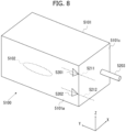
Fig. 10 is a view illustrating a schematic configuration of a measuring apparatus according to a modification. - An application example of the present invention will be described. In the prior art, since the visibility of the pointer indicating the microwave irradiation range depends on the environment (brightness, etc.) in which the measuring apparatus is installed, the measurement accuracy of the biological information of the person to be measured may decrease depending on the installation environment of the measuring apparatus.
-
Fig. 1 is a view schematically illustrating an example of use of a measuringapparatus 100 to which the present invention is applied. In the example of use illustrated inFig. 1 , the measuringapparatus 100 includes anantenna 102 that transmits and receives a signal for acquiring biological information to and from a person to be measured in acasing 101 that is a rectangular parallelepiped exterior member. The measuringapparatus 100 performs so-called non-contact biological information sensing. A signal transmitted by theantenna 102 passes through afront surface 101a of thecasing 101, reaches the person to be measured, is reflected from the person to be measured, and is detected by theantenna 102 that is a signal detector. Examples of the frequency of the signal transmitted from theantenna 102 to the person to be measured include frequencies in a frequency band of 30 GHz to 300 GHz used for a millimeter-wave radar, but frequencies in other frequency bands such as light, radio waves, sound waves, and ultrasonic waves may be adopted. Although the shape of theantenna 102 is schematically illustrated as an ellipse inFig. 1 , various shapes may be adopted as the shape of theantenna 102. In the following description, the measuringapparatus 100 includes theantenna 102, but a signal detector may be adopted in place of theantenna 102 in the measuringapparatus 100 according to the frequency of the signal to be used. A signal transmission method to be used may be a continuous wave such as frequency modulated continuous wave (FM-CW) or CW, or may be an intermittent wave. Theantenna 102 may be formed of a transmission antenna and a reception antenna separately. - The measuring
apparatus 100 has asighting device 200 disposed on anupper surface 101b of thecasing 101 for a user of the measuringapparatus 100, the person to be measured, or others to confirm the signal detection range (signal transmission range) of theantenna 102. Thesighting device 200 is fixed to theupper surface 101b by a mounting member (not illustrated). Thesighting device 200 includes amain body 201, and themain body 201 is provided with avisible mark 202 and awindow portion 203. The material of thesighting device 200 is not particularly limited, but more preferably, thesighting device 200 is formed of a material having a low relative permittivity, such as plastic, which does not interfere with signals transmitted and received by theantenna 102 as much as possible. The size of thewindow portion 203 is determined based on the directivity of theantenna 102 such that a position is within the signal detection range of theantenna 102 as long as themark 202 is visible through thewindow portion 203 from that position. The relationship between the range in which themark 202 is visible through thewindow portion 203 and the signal detection range of theantenna 102 will be described later. - By providing such a
sighting device 200 separately from the measuringapparatus 100 or integrally with the measuringapparatus 100, the user of the measuringapparatus 100 or the person to be measured can specify the signal detection range of theantenna 102 with a simple configuration. This can prevent the person to be measured from being out of the signal detection range of theantenna 102, improving the measurement accuracy of the measuringapparatus 100. - A first embodiment of the technique of the present disclosure will be described. First, in
Fig. 1 , XYZ axes orthogonal to each other are determined. In the embodiment, thecasing 101 is a rectangular parallelepiped exterior member, and XYZ axes are determined such that a YZ plane is a plane parallel to thefront surface 101a (and the back surface) of thecasing 101, an XY plane is a plane parallel to theupper surface 101b (and the bottom surface) of thecasing 101, and an XZ plane is a plane parallel to aside surface 101c of thecasing 101. -
Fig. 2A illustrates a front view of thesighting device 200 fixed to the measuringapparatus 100, andFig. 2B illustrates a side view of thesighting device 200. As illustrated inFig. 2B , thesighting device 200 includes a flat plate-shapedbase 200a parallel to the XY plane and two flat plate-shapedwalls base 200a in a direction parallel to the Z axis. Thewalls wall 200b is provided with thewindow portion 203 penetrating thewall 200b in the X-axis direction, and themark 202 is provided on thewall 200b side of thewall 200c. Themark 202 is formed using various paints as long as the user of the measuringapparatus 100 or the person to be measured can view themark 200. Note that themark 202 may be formed using a known technique, such as a projection or a recess formed on the surface of thewall 200c, a light-emitting diode (LED) lamp provided on thewall 200c, or a seal attached to thewall 200c, as long as themark 202 are visible. - As illustrated in
Fig. 2A , thewindow portion 203 is an elliptical window portion as viewed in the X-axis direction. As the shape of thewindow portion 203, various shapes may be appropriately adopted according to the directivity of theantenna 102. Themark 202 is formed on thewall 200c at a position where themark 202 can be viewed so as to overlap with the intersection of the major and minor axes of the ellipse of thewindow portion 203 when thewindow portion 203 is viewed in the X-axis direction. Therefore, when thesighting device 200 is viewed in the X-axis direction from thefront surface 101a side of thecasing 101 of the measuringapparatus 100, themark 202 is visible through thewindow portion 203. InFigs. 2A and2B , thesighting device 200 is divided into thebase 200a and thewalls base 200a and thewalls Fig. 1 . - Next, the relationship between the range in which the
mark 202 is visible through thewindow portion 203 and the signal detection range of theantenna 102 will be described with reference toFigs. 3A and3B .Fig. 3A is a view schematically illustrating arange 210 in which themark 202 is visible through thewindow portion 203 and asignal detection range 110 of theantenna 102 in a top view of thecasing 101 of the measuringapparatus 100. Similarly,Fig. 3B is a view schematically illustrating therange 210 in which themark 202 is visible through thewindow portion 203 and thesignal detection range 110 of theantenna 102 in a side view of thecasing 101 of the measuringapparatus 100. - The
signal detection range 110 of theantenna 102 is determined based on the directivity of theantenna 102 with reference to acenter 103 of theantenna 102 that receives a signal from the person to be measured. In the embodiment, as illustrated inFig. 3A , it is assumed that theantenna 102 and themark 202 are arranged such that thecenter 103 of the antenna 102 (in this example, the intersection of the major and minor axes of the ellipse of the antenna 102) and themark 202 substantially overlap in the top view of thecasing 101 of the measuringapparatus 100. In addition, as illustrated inFig. 3B , it is assumed that theantenna 102 and themark 202 are arranged such that thecenter 103 of theantenna 102 and themark 202 are aligned vertically in the side view of thecasing 101 of the measuringapparatus 100. - At this time, the
range 210 in which themark 202 is visible through thewindow portion 203 is formed on thefront surface 101a side of thecasing 101. Thesignal detection range 110 of theantenna 102 is formed on thefront surface 101a side of thecasing 101. Then, an area A is formed where at least a part of therange 210, in which themark 202 is visible, is included in thesignal detection range 110. Therefore, when the person to be measured is within that area A, a signal can be detected by theantenna 102. For example, as illustrated inFigs. 3A and3B , when measurement is performed on a person to be measured on abed 300 with the measuringapparatus 100, it is confirmed in advance that the user can view themark 202 through thewindow portion 203 from the four corners of thebed 300 or from the top of thebed 300. This makes it possible to more reliably detect a signal from the person to be measured with theantenna 102 and obtain a more accurate measurement result than when measurement is performed without using thesighting device 200. - In addition, since the position of the
center 103 of theantenna 102 differs from the position of themark 202, in the example ofFigs. 3A and3B , thesignal detection range 110 of theantenna 102 does not overlap with therange 210 in which themark 202 is visible through thewindow portion 203 in the range of a distance D1 from thefront surface 101a of thecasing 101. Moreover, in the range of a distance D2 from thefront surface 101a of thecasing 101, there is an area where thesignal detection range 110 of theantenna 102 and therange 210 in which themark 202 is visible through thewindow portion 203 do not overlap. Thus, in the area within the distance D1 or distance D2 from thefront surface 101a of thecasing 101, there is a possibility that the signal cannot be detected by theantenna 102 even though themark 202 can be confirmed through thewindow portion 203. Therefore, when the measuringapparatus 100 is used, setting a limit on the position of the person to be measured, such as ensuring the person to be measured at a distance greater than the distance D1 or distance D2 from thefront surface 101a of thecasing 101, can further improve the measurement accuracy of the measuringapparatus 100. - In the above example, the relative position between the
mark 202 and thewindow portion 203 is a position at which themark 202 can be viewed so as to overlap with the intersection of the major and minor axes of the ellipse of thewindow portion 203 when thewindow portion 203 is viewed in the X-axis direction. However, the relative position between themark 202 and thewindow portion 203 may be appropriately changed according to the directivity of theantenna 102. Even if thecenter 103 of theantenna 102 and themark 202 are arranged at positions shifted from each other in the top view of thecasing 101 of the measuringapparatus 100, when themark 202 can be viewed through thewindow portion 203 by changing the relative position between themark 202 and thewindow portion 203 according to the directivity of theantenna 102, it is possible to detect a signal from the person to be measured with theantenna 102 and obtain a more accurate measurement result. - Next, a second embodiment of the technique of the present disclosure will be described. In the measuring
apparatus 100 according to the first embodiment, thesighting device 200 is configured separately from the measuringapparatus 100. However, the sighting device can also be configured integrally with the measuring apparatus. -
Fig. 4 illustrates an example of ameasuring apparatus 1100 according to the embodiment. As illustrated inFig. 4 , in themeasuring apparatus 1100, anantenna 1102 is disposed in acasing 1101 that is a rectangular parallelepiped exterior member. Arecess 1204, where a part of afront surface 1101a is recessed in the X-axis direction, is formed in thefront surface 1101a of thecasing 1101. Therecess 1204 includes anelliptical opening 1203 similar to thewindow portion 203 of the first embodiment and abottom surface 1204a having a shape corresponding to the shape of theopening 1203. Amark 1202 corresponding to themark 202 of the first embodiment is formed on a bottom 1204a that is a part of the inner surface of therecess 1204. - In this embodiment, similarly to the first embodiment, it is assumed that the
antenna 1102 and themark 1202 are arranged such that a center 1103 of theantenna 1102 and themark 1202 substantially overlap in a top view of thecasing 1101 of themeasuring apparatus 1100, and such that thecenter 103 of theantenna 102 and themark 202 are aligned vertically in a side view of thecasing 1101 of themeasuring apparatus 1100. - In this embodiment, the
opening 1203 of therecess 1204 corresponds to thewindow portion 203 of the first embodiment, themark 1202 of therecess 1204 corresponds to themark 202 of the first embodiment, and therecess 1204 including theopening 1203 and themark 1202 functions as a sighting device corresponding to thesighting device 200 of the first embodiment. Thus, it is possible to determine whether a user of themeasuring apparatus 1100 or a person to be measured is within the signal detection range of theantenna 1102, based on whether themark 1202 is visible through theopening 1203 of therecess 1204. - Therefore, in this embodiment as well, similarly to the example of the first embodiment, when measurement is performed on the person to be measured with the
measuring apparatus 1100, it is confirmed in advance that the user can view themark 1202 through theopening 1203 of therecess 1204. This makes it possible to more reliably detect a signal from the person to be measured with theantenna 1102 and obtain a more accurate measurement result than when the measurement is performed without using the configuration like therecess 1204. - In addition, in the
measuring apparatus 1100 of this embodiment, since therecess 1204 functioning as a sighting device is formed in a part of thefront surface 1101a of thecasing 1101, themark 1202 can be disposed at a position closer to the center of theantenna 1102 compared to the first embodiment. Thus, the area where the range in which the mark is visible and the signal detection range of the antenna overlap is larger than in the case of the first embodiment. As a result, it is possible to more reliably perform signal detection on the person to be measured with theantenna 1102 and to further improve the measurement accuracy of themeasuring apparatus 1100. - In the above example, the
recess 1204 is formed as an elliptic columnar cavity, but the inner surface shape of therecess 1204 is not limited thereto. For example, the inner surface of therecess 1204 may be formed of a paraboloid surface, and themark 1202 may be provided on a part of the paraboloid surface. - The above embodiments are merely illustrative examples of the configurations of the present invention. The present invention is not limited to the specific forms described above, and various modifications can be made within the scope of the technical idea. In the following, modifications of the above embodiments will be described. Note that the embodiments described above and the modifications described below can be appropriately combined and implemented.
- A
measuring apparatus 2100 according to Modification 1 will be described below.Fig. 5 illustrates an example of themeasuring apparatus 2100 according to the present modification. As illustrated inFig. 5 , in themeasuring apparatus 2100, anantenna 2102 is disposed in acasing 2101 that is a rectangular parallelepiped exterior member. In themeasuring apparatus 2100 as well, similarly to the above embodiments, a signal transmitted by theantenna 2102 passes through afront surface 2101a of thecasing 2101, reaches a person to be measured, is reflected by the person to be measured, and is detected by theantenna 2102. - On an
upper surface 2101b that is the outer surface of thecasing 2101, threecolumnar rod members upper surface 2101b are provided. Note that therod members 2201 to 2203 may be removably provided on thecasing 2101, or may be integrally provided with thecasing 2101. On theupper surface 2101b, tworod members rod members 2201 to 2203 are disposed closer to thefront surface 2101a than the remainingrod member 2203. In the present modification, the threerod members 2201 to 2203 function as a sighting device corresponding to thesighting device 200 of the first embodiment. - In a top view of the
casing 2101, therod member 2203 is disposed at a position substantially overlapping with the center of theantenna 2102, similarly to themarks casing 2101, the positions of therod members rod member 2203 is visible between therod members front surface 2101a side of thecasing 2101 is included in the signal detection range of theantenna 2102. As a result, therod members rod member 2203 to specify the position as being within the signal detection range of theantenna 2102 in the azimuth angle (the angle of rotation about the Z axis in the XY plane) direction of theantenna 2102. - Thus, in the present modification as well, similarly to the area A illustrated in
Fig. 3A in the first embodiment, on thefront surface 2101a side of thecasing 2101, it is possible to form an area where the range in which therod member 2203 is visible between therod members antenna 2102. Therefore, when the person to be measured is within that area, the signal can be detected by theantenna 2102. - According to the present modification, the measurement accuracy of the measuring apparatus can be expected to be improved by placing the person to be measured within the signal detection range of the antenna, using a simpler configuration than the
sighting device 200 of the first embodiment. - Next, a
measuring apparatus 3100 according to Modification 2 will be described.Fig. 6 illustrates an example of themeasuring apparatus 3100 according to the present modification. As illustrated inFig. 6 , in themeasuring apparatus 3100, anantenna 3102 is disposed in acasing 3101 that is a rectangular parallelepiped exterior member. In themeasuring apparatus 3100 as well, similarly to the above embodiments and modification, a signal transmitted by theantenna 3102 passes through afront surface 3101a of thecasing 3101, reaches a person to be measured, is reflected by the person to be measured, and is detected by theantenna 3102. - On a
side surface 3101c that is the outer surface of thecasing 3101, threecolumnar rod members side surface 3101c are provided. Note that therod members 3201 to 3203 may be removably provided on thecasing 3101, or may be integrally provided with thecasing 3101. On theside surface 3101c, tworod members rod members 3201 to 3203 are disposed closer to thefront surface 3101a than the remainingrod member 3203. In the present modification, the threerod members 3201 to 3203 function as a sighting device corresponding to thesighting device 200 of the first embodiment. - In a side view of the
casing 3101, therod member 3203 is disposed at a position substantially overlapping with the center of theantenna 3102. In the side view of thecasing 3101, the positions of therod members rod member 3203 is visible between therod members front surface 3101a side of thecasing 3101 is included in the signal detection range of theantenna 3102. As a result, therod members rod member 3203 to specify the position as being within the signal detection range of theantenna 3102 in the elevation angle (the angle of rotation about the Y axis in the XZ plane) direction of theantenna 3102. - Thus, in the present modification as well, similarly to the area A illustrated in
Fig. 3B in the first embodiment, on thefront surface 3101a side of thecasing 3101, it is possible to form an area where the range in which therod member 3203 is visible between therod members antenna 3102. Therefore, when the person to be measured is within that area, the signal can be detected by theantenna 3102. - According to the present modification, similarly to Modification 1, the measurement accuracy of the measuring apparatus can be expected to be improved by placing the person to be measured within the signal detection range of the antenna, using a simpler configuration than the
sighting device 200 of the first embodiment. - Next, a
measuring apparatus 4100 according to Modification 3 will be described.Fig. 7 illustrates an example of themeasuring apparatus 4100 according to the present modification. As illustrated inFig. 7 , in themeasuring apparatus 4100, anantenna 4102 is disposed in acasing 4101 that is a rectangular parallelepiped exterior member. In themeasuring apparatus 4100 as well, similarly to the above embodiments and modifications, a signal transmitted by theantenna 4102 passes through afront surface 4101a of thecasing 4101, reaches a person to be measured, is reflected by the person to be measured, and is detected by theantenna 4102. - Further, two
marks front surface 4101a of thecasing 4101. Themarks front surface 4101a. On anupper surface 4101b of thecasing 4101, acolumnar rod member 4203 extending in the Z-axis direction from theupper surface 4101b is provided. Themarks rod members virtual boundary lines antenna 4102 when therod member 4203 is viewed to confirm the signal detection range of the antenna 4120. Thevirtual boundary lines marks marks marks marks rod member 4203 function as a sighting device corresponding to thesighting device 200 of the first embodiment. - In a top view of the
casing 4101, therod member 4203 is disposed at a position substantially overlapping with the center of theantenna 4102, similarly to therod member 2203 described above. Further, in the top view of thecasing 4101, the positions of themarks rod member 4203 is visible between thevirtual boundary lines marks front surface 4101a side of thecasing 4101 is included in the signal detection range in the azimuth angle direction of theantenna 4102. Therefore, thevirtual boundary lines marks rod member 4203 to specify the position as being within the signal detection range of theantenna 4102 in the azimuth angle (the angle of rotation about the Z axis in the XY plane) direction of theantenna 4102. Accordingly, in the present modification as well, similarly to Modification 1, on thefront surface 4101a side of thecasing 4101, it is possible to form an area where the range in which therod member 4203 is visible between thevirtual boundary lines marks antenna 4102. Therefore, when the person to be measured is within that area, the signal can be detected by theantenna 4102. - According to the present modification, the measurement accuracy of the measuring apparatus can be expected to be improved by placing the person to be measured within the signal detection range of the antenna, using a simpler configuration than the
sighting device 200 of the first embodiment. - Next, a
measuring apparatus 5100 according to Modification 4 will be described.Fig. 8 illustrates an example of themeasuring apparatus 5100 according to the present modification. As illustrated inFig. 8 , in themeasuring apparatus 5100, anantenna 5102 is disposed in acasing 5101 that is a rectangular parallelepiped exterior member. In themeasuring apparatus 5100 as well, similarly to the above embodiments and modifications, a signal transmitted by theantenna 5102 passes through afront surface 5101a of thecasing 5101, reaches a person to be measured, is reflected by the person to be measured, and is detected by theantenna 5102. - Two
marks front surface 5101a of thecasing 5101. Themarks front surface 5101a in the horizontal direction. On aside surface 5101c of thecasing 5101, acolumnar rod member 5203 extending in the Y-axis direction from theside surface 5101c is provided. Themarks marks virtual boundary lines rod member 5203 is viewed to confirm the signal detection range of theantenna 5102. Thevirtual boundary lines marks marks marks marks rod member 5203 function as a sighting device corresponding to thesighting device 200 of the first embodiment. - In a side view of the
casing 5101, therod member 5203 is disposed at a position substantially overlapping with the center of theantenna 5102, similarly to therod member 3203 described above. In the side view of thecasing 5101, the positions of themarks rod member 5203 is visible between thevirtual boundary lines marks front surface 5101a side of thecasing 5101 is included in the signal detection range of theantenna 5102. Therefore, thevirtual boundary lines marks 5201, 4502, determine the viewing range of therod member 5203 to specify the position as being within the signal detection range of theantenna 5102 in the elevation angle (the angle of rotation about the Y axis in the XZ plane) direction of theantenna 5102. Accordingly, in the present modification as well, similarly to Modification 3, on thefront surface 5101a side of thecasing 5101, it is possible to form an area where the range in which therod member 5203 is visible between thevirtual boundary lines marks antenna 5102. Therefore, when the person to be measured is within that area, the signal can be detected by theantenna 5102. - According to the present modification, the measurement accuracy of the measuring apparatus can be expected to be improved by placing the person to be measured within the signal detection range of the antenna, using a simpler configuration than the
sighting device 200 of the first embodiment. - Next, a
measuring apparatus 6100 according to Modification 5 will be described.Fig. 9 illustrates an example of themeasuring apparatus 6100 according to the present modification. As illustrated inFig. 9 , in themeasuring apparatus 6100, anantenna 6102 is disposed in acasing 6101 that is a rectangular parallelepiped exterior member. In themeasuring apparatus 6100 as well, similarly to the above embodiments, a signal transmitted by theantenna 6102 passes through afront surface 6101a of thecasing 6101, reaches a person to be measured, is reflected by the person to be measured, and is detected by theantenna 6102. - In the present modification, the
walls sighting device 200 of the first embodiment are configured asseparate walls window portion 6203 corresponding to thewindow portion 203 of the first embodiment is formed in thewall 6210, and amark 6202 corresponding to themark 202 of the first embodiment is formed of thewall 6220. Thewalls upper surface 6101b of thecasing 6101 using respective mounting member (not illustrated). Note that the mounting member can be implemented using a known technique, and therefore a detailed description thereof will be omitted. In the present modification, the twowalls sighting device 200 of the first embodiment. - When the
walls upper surface 6101b, the relationship among themark 6202, thewindow portion 6203, and the center of theantenna 6102 corresponds to the relationship among themark 202, thewindow portion 203, and the center of theantenna 102 in the first embodiment. Thus, on thefront surface 6101a side of thecasing 6101, an area is formed where the range in which themark 6202 is visible through thewindow portion 6203 is included in the signal detection range of theantenna 6102. Therefore, when the person to be measured is within that area, the signal can be detected by theantenna 6102. - According to the present modification, the measurement accuracy of the measuring apparatus can be expected to be improved by placing the person to be measured within the signal detection range of the antenna, using a configuration similar to the
sighting device 200 of the first embodiment. - Next, a
measuring apparatus 7100 according to Modification 6 will be described.Fig. 10 illustrates an example of themeasuring apparatus 7100 according to the present modification. As illustrated inFig. 10 , themeasuring apparatus 7100 has a configuration similar to the measuringapparatus 100 and thesighting device 200 in the first embodiment. Therefore, in the following description, components similar to those of the first embodiment are denoted by the same reference numerals, and a detailed description thereof will be omitted. - In the present modification, the
measuring apparatus 7100 includes a flat plate-shapedpedestal 7400 and acylindrical support portion 7300 for supporting thecasing 101 to which thesighting device 200 is fixed. Moreover, themeasuring apparatus 7100 includes anadjuster 7200 for changing the orientation of thecasing 101, the orientation of thesighting device 200 fixed to thecasing 101 in the azimuth angle (the angle of rotation about the Z axis in the XY plane) direction and the elevation angle (the angle of rotation about the Y axis in the XZ plane) direction of theantenna 102. As an example, theadjuster 7200 rotates thecasing 101 about the Y axis and the Z axis. The rotation mechanism of theadjuster 7200 can be implemented by using a known technique, and therefore a detailed description thereof will be omitted here. Theadjuster 7200 may be configured to change the orientation of thesighting device 200 in at least one of the azimuth angle direction or the elevation angle direction of theantenna 102. - Thus, since the direction of the
sighting device 200 can be changed in accordance with the position of the person to be measured at the time of measurement, the measurement accuracy of the measuring apparatus can be expected to be improved by changing the signal detection range of the antenna according to the use environment of themeasuring apparatus 7100 and by placing the person to be measured within the signal detection range of the antenna. - Next, a measuring apparatus according to Modification 7 will be described. In the present modification, components similar to those of the above embodiments are denoted by the same reference numerals, and a detailed description thereof will be omitted. In the present modification, as an example, an infrared sensor is provided instead of the
mark 202 in thesighting device 200 of the first embodiment described above. TheWall 200b in which thewindow portion 203 is formed is made of a material that hardly transmits or substantially blocks infrared light used for the infrared sensor. By using thesighting device 200 configured as described above, the measuringapparatus 100 can detect a person within the signal detection range of theantenna 102 with the infrared sensor and notify the person with a lamp, a speaker, or the like (not illustrated). This enables a user of the measuringapparatus 100, a person to be measured, or others to confirm whether he or she is within the signal detection range of theantenna 102 by using thesighting device 200. As a result, in the present modification as well, it is possible to more reliably detect a signal from the person to be measured with theantenna 102 and obtain a more accurate measurement result than when measurement is performed without using thesighting device 200. - A sighting device (200) used in a measuring apparatus (100) including a signal detector (102) that detects a signal related to biological information reflected from a person to be measured, the sighting device including:
- a visible indicator (202); and
- a viewing range specifier (203) configured to specify a viewing range of the indicator,
- in which a relative position between the indicator and the viewing range specifier is determined such that the viewing range of the indicator specified by the viewing range specifier forms an area included in a detection range of the signal by the signal detector.
-
- 100
- measuring apparatus
- 102
- antenna
- 200
- sighting device
- 202
- mark
- 203
- window portion
Claims (7)
- A sighting device used in a measuring apparatus including a signal detector that detects a signal related to biological information reflected from a person to be measured, the sighting device comprising:a visible indicator; anda viewing range specifier configured to specify a viewing range of the indicator,wherein a relative position between the indicator and the viewing range specifier is determined such that the viewing range of the indicator specified by the viewing range specifier forms an area included in a detection range of the signal by the signal detector.
- The sighting device according to claim 1, whereinthe indicator is formed on an inner surface of a recess formed in an exterior member of the measuring apparatus, andthe viewing range specifier is an opening of the recess.
- The sighting device according to claim 1, further comprising two walls facing each other, whereinthe indicator is formed on one wall of the two walls, andthe viewing range specifier is a window portion penetrating another wall of the two walls.
- The sighting device according to claim 1, wherein the viewing range specifier is two rod members extending from an outer surface of an exterior member of the measuring apparatus, the two rod members being disposed at positions for specifying a viewing range of the indicator in at least one of an azimuth angle direction or an elevation angle direction as viewed from the signal detector.
- The sighting device according to claim 1, wherein the viewing range specifier is two indicators visible from an outside of the measuring apparatus, the two indicators being disposed at positions for specifying a viewing range of the indicator in at least one of an azimuth angle direction or an elevation angle direction as viewed from the signal detector.
- A measuring apparatus comprising the sighting device according to any one of claims 1 to 5 and the signal detector.
- The measuring apparatus according to claim 6, further comprising an adjuster configured to change a direction of the sighting device in at least one of an azimuth angle direction or an elevation angle direction as viewed from the signal detector.
Applications Claiming Priority (2)
| Application Number | Priority Date | Filing Date | Title |
|---|---|---|---|
| JP2022027040A JP7779172B2 (en) | 2022-02-24 | 2022-02-24 | sights and measuring devices |
| PCT/JP2023/002655 WO2023162576A1 (en) | 2022-02-24 | 2023-01-27 | Sighting device and measurement device |
Publications (2)
| Publication Number | Publication Date |
|---|---|
| EP4458255A1 true EP4458255A1 (en) | 2024-11-06 |
| EP4458255A4 EP4458255A4 (en) | 2025-10-08 |
Family
ID=87765522
Family Applications (1)
| Application Number | Title | Priority Date | Filing Date |
|---|---|---|---|
| EP23759582.2A Pending EP4458255A4 (en) | 2022-02-24 | 2023-01-27 | SIGHTING DEVICE AND MEASURING DEVICE |
Country Status (5)
| Country | Link |
|---|---|
| US (1) | US20250123099A1 (en) |
| EP (1) | EP4458255A4 (en) |
| JP (1) | JP7779172B2 (en) |
| CN (1) | CN118574564A (en) |
| WO (1) | WO2023162576A1 (en) |
Family Cites Families (9)
| Publication number | Priority date | Publication date | Assignee | Title |
|---|---|---|---|---|
| JPS52149675U (en) * | 1976-05-08 | 1977-11-12 | ||
| JP2000147631A (en) * | 1998-11-05 | 2000-05-26 | Casio Comput Co Ltd | Imaging device and imaging range confirmation member |
| JP2010200199A (en) * | 2009-02-27 | 2010-09-09 | Panasonic Corp | Imaging device and imaging range checking member |
| JP6587238B2 (en) | 2015-08-01 | 2019-10-09 | 吉田 一雄 | Non-contact vital information monitoring system |
| JP6811559B2 (en) * | 2015-09-07 | 2021-01-13 | 株式会社デンソーウェーブ | Optical information reader |
| JP6984448B2 (en) * | 2018-01-30 | 2021-12-22 | 住友電気工業株式会社 | Sight, radio sensor and adjustment method |
| KR102544669B1 (en) * | 2018-04-12 | 2023-06-16 | 삼성전자주식회사 | Apparatus and method for measuring bio-information |
| US11082769B2 (en) * | 2019-11-15 | 2021-08-03 | Bose Corporation | Audio visualization in telecommunications applications |
| US12392892B2 (en) * | 2019-12-10 | 2025-08-19 | Sumitomo Electric Industries, Ltd. | Method for installing radio wave sensor, radio wave sensor, and adjustment device |
-
2022
- 2022-02-24 JP JP2022027040A patent/JP7779172B2/en active Active
-
2023
- 2023-01-27 US US18/834,121 patent/US20250123099A1/en active Pending
- 2023-01-27 CN CN202380019769.5A patent/CN118574564A/en active Pending
- 2023-01-27 WO PCT/JP2023/002655 patent/WO2023162576A1/en not_active Ceased
- 2023-01-27 EP EP23759582.2A patent/EP4458255A4/en active Pending
Also Published As
| Publication number | Publication date |
|---|---|
| JP7779172B2 (en) | 2025-12-03 |
| US20250123099A1 (en) | 2025-04-17 |
| CN118574564A (en) | 2024-08-30 |
| WO2023162576A1 (en) | 2023-08-31 |
| EP4458255A4 (en) | 2025-10-08 |
| JP2023123151A (en) | 2023-09-05 |
Similar Documents
| Publication | Publication Date | Title |
|---|---|---|
| US10698094B2 (en) | 3D-position determination method and device | |
| US8035546B2 (en) | Method for detecting at least one moving object | |
| JP2003506704A (en) | Level transmitter | |
| US7474256B2 (en) | Position detecting system, and transmitting and receiving apparatuses for the position detecting system | |
| US10001398B2 (en) | Fill-level measuring device and apparatus for determining the dielectric constant | |
| JPH11194165A (en) | Axis adjustment method for automotive radar | |
| US20100031753A1 (en) | Apparatus for ascertaining and/or monitoring fill level and/or flow of a medium | |
| JP2014510264A (en) | Millimeter-wave energy detector and method | |
| US6445193B1 (en) | Distance measuring device and method for determining a distance | |
| US10982989B2 (en) | Fill level measuring device | |
| CN104871028A (en) | Method for generating an image and handheld screening device | |
| US12392892B2 (en) | Method for installing radio wave sensor, radio wave sensor, and adjustment device | |
| EP3264073B1 (en) | Measuring device | |
| US20130015997A1 (en) | Distance measuring device and method for determining a distance, and a suitable reflective member | |
| US20250123099A1 (en) | Sighting device and measurement device | |
| US5191348A (en) | Radar detector performance verification method and apparatus | |
| CN114047501B (en) | Indoor positioning system based on millimeter wave radar | |
| US20180335512A1 (en) | mm-Wave Radar Sensor for Distance Measurement in Short and Medium Range | |
| CN109863421B (en) | Signal processing device, radar device and signal processing method | |
| JP2005098897A (en) | In-vehicle radar device, in-vehicle radar reflector, and method for adjusting mounting angle of in-vehicle radar device | |
| JP2010190612A (en) | Axis adjustment target device | |
| US11860025B2 (en) | System for recognizing and/or determining the volume of bodies or substances made of dielectric and/or conductive material | |
| RU2008149718A (en) | METHOD FOR MEASURING COORDINATES AIMS OF MOBILE RADAR AND DEVICE FOR ITS IMPLEMENTATION | |
| JP2000206230A (en) | Radar cross section measuring method and radar cross section measuring device | |
| US20090161105A1 (en) | Method for Ascertaining and Monitoring Fill Level of a Medium In a Container Using the Travel-Time Method |
Legal Events
| Date | Code | Title | Description |
|---|---|---|---|
| STAA | Information on the status of an ep patent application or granted ep patent |
Free format text: STATUS: THE INTERNATIONAL PUBLICATION HAS BEEN MADE |
|
| PUAI | Public reference made under article 153(3) epc to a published international application that has entered the european phase |
Free format text: ORIGINAL CODE: 0009012 |
|
| STAA | Information on the status of an ep patent application or granted ep patent |
Free format text: STATUS: REQUEST FOR EXAMINATION WAS MADE |
|
| 17P | Request for examination filed |
Effective date: 20240730 |
|
| AK | Designated contracting states |
Kind code of ref document: A1 Designated state(s): AL AT BE BG CH CY CZ DE DK EE ES FI FR GB GR HR HU IE IS IT LI LT LU LV MC ME MK MT NL NO PL PT RO RS SE SI SK SM TR |
|
| DAV | Request for validation of the european patent (deleted) | ||
| DAX | Request for extension of the european patent (deleted) | ||
| A4 | Supplementary search report drawn up and despatched |
Effective date: 20250910 |
|
| RIC1 | Information provided on ipc code assigned before grant |
Ipc: A61B 5/00 20060101AFI20250904BHEP Ipc: A61B 5/0507 20210101ALI20250904BHEP Ipc: A61B 5/02 20060101ALI20250904BHEP Ipc: A61B 5/024 20060101ALI20250904BHEP |