EP4457500B1 - Photoakustischer spektroskopiesensor zur spurengasdetektion und verfahren zur spurengasdetektion - Google Patents
Photoakustischer spektroskopiesensor zur spurengasdetektion und verfahren zur spurengasdetektion Download PDFInfo
- Publication number
- EP4457500B1 EP4457500B1 EP22844526.8A EP22844526A EP4457500B1 EP 4457500 B1 EP4457500 B1 EP 4457500B1 EP 22844526 A EP22844526 A EP 22844526A EP 4457500 B1 EP4457500 B1 EP 4457500B1
- Authority
- EP
- European Patent Office
- Prior art keywords
- transducer
- interferometer
- signal
- chamber
- arm
- Prior art date
- Legal status (The legal status is an assumption and is not a legal conclusion. Google has not performed a legal analysis and makes no representation as to the accuracy of the status listed.)
- Active
Links
Images


Classifications
-
- G—PHYSICS
- G01—MEASURING; TESTING
- G01N—INVESTIGATING OR ANALYSING MATERIALS BY DETERMINING THEIR CHEMICAL OR PHYSICAL PROPERTIES
- G01N21/00—Investigating or analysing materials by the use of optical means, i.e. using sub-millimetre waves, infrared, visible or ultraviolet light
- G01N21/17—Systems in which incident light is modified in accordance with the properties of the material investigated
- G01N21/1702—Systems in which incident light is modified in accordance with the properties of the material investigated with opto-acoustic detection, e.g. for gases or analysing solids
-
- G—PHYSICS
- G01—MEASURING; TESTING
- G01N—INVESTIGATING OR ANALYSING MATERIALS BY DETERMINING THEIR CHEMICAL OR PHYSICAL PROPERTIES
- G01N21/00—Investigating or analysing materials by the use of optical means, i.e. using sub-millimetre waves, infrared, visible or ultraviolet light
- G01N21/17—Systems in which incident light is modified in accordance with the properties of the material investigated
- G01N21/25—Colour; Spectral properties, i.e. comparison of effect of material on the light at two or more different wavelengths or wavelength bands
- G01N21/27—Colour; Spectral properties, i.e. comparison of effect of material on the light at two or more different wavelengths or wavelength bands using photo-electric detection ; circuits for computing concentration
- G01N21/274—Calibration, base line adjustment, drift correction
-
- G—PHYSICS
- G01—MEASURING; TESTING
- G01N—INVESTIGATING OR ANALYSING MATERIALS BY DETERMINING THEIR CHEMICAL OR PHYSICAL PROPERTIES
- G01N29/00—Investigating or analysing materials by the use of ultrasonic, sonic or infrasonic waves; Visualisation of the interior of objects by transmitting ultrasonic or sonic waves through the object
- G01N29/02—Analysing fluids
-
- G—PHYSICS
- G01—MEASURING; TESTING
- G01N—INVESTIGATING OR ANALYSING MATERIALS BY DETERMINING THEIR CHEMICAL OR PHYSICAL PROPERTIES
- G01N29/00—Investigating or analysing materials by the use of ultrasonic, sonic or infrasonic waves; Visualisation of the interior of objects by transmitting ultrasonic or sonic waves through the object
- G01N29/22—Details, e.g. general constructional or apparatus details
- G01N29/24—Probes
- G01N29/2418—Probes using optoacoustic interaction with the material, e.g. laser radiation, photoacoustics
- G01N29/2425—Probes using optoacoustic interaction with the material, e.g. laser radiation, photoacoustics optoacoustic fluid cells therefor
-
- G—PHYSICS
- G01—MEASURING; TESTING
- G01N—INVESTIGATING OR ANALYSING MATERIALS BY DETERMINING THEIR CHEMICAL OR PHYSICAL PROPERTIES
- G01N21/00—Investigating or analysing materials by the use of optical means, i.e. using sub-millimetre waves, infrared, visible or ultraviolet light
- G01N21/17—Systems in which incident light is modified in accordance with the properties of the material investigated
- G01N21/1702—Systems in which incident light is modified in accordance with the properties of the material investigated with opto-acoustic detection, e.g. for gases or analysing solids
- G01N2021/1704—Systems in which incident light is modified in accordance with the properties of the material investigated with opto-acoustic detection, e.g. for gases or analysing solids in gases
-
- G—PHYSICS
- G01—MEASURING; TESTING
- G01N—INVESTIGATING OR ANALYSING MATERIALS BY DETERMINING THEIR CHEMICAL OR PHYSICAL PROPERTIES
- G01N2201/00—Features of devices classified in G01N21/00
- G01N2201/06—Illumination; Optics
- G01N2201/061—Sources
- G01N2201/06113—Coherent sources; lasers
-
- G—PHYSICS
- G01—MEASURING; TESTING
- G01N—INVESTIGATING OR ANALYSING MATERIALS BY DETERMINING THEIR CHEMICAL OR PHYSICAL PROPERTIES
- G01N2291/00—Indexing codes associated with group G01N29/00
- G01N2291/02—Indexing codes associated with the analysed material
- G01N2291/021—Gases
-
- G—PHYSICS
- G01—MEASURING; TESTING
- G01N—INVESTIGATING OR ANALYSING MATERIALS BY DETERMINING THEIR CHEMICAL OR PHYSICAL PROPERTIES
- G01N2291/00—Indexing codes associated with group G01N29/00
- G01N2291/02—Indexing codes associated with the analysed material
- G01N2291/028—Material parameters
- G01N2291/02809—Concentration of a compound, e.g. measured by a surface mass change
Definitions
- the present invention relates to a photoacoustic sensor to detect traces of selected molecular species in a gas. Furthermore, the invention relates to a method to detect traces of a gas using a photoacoustic phenomenon.
- Modern photo-acoustic spectroscopic (PAS) techniques such as cantilever-enhanced photo-acoustic spectroscopy (CEPAS), quartz-enhanced photo-acoustic spectroscopy (QEPAS) and variants of cavity-enhanced photo-acoustic spectroscopy are also techniques known in the art which can achieve high sensitivities.
- CEPAS cantilever-enhanced photo-acoustic spectroscopy
- QEPAS quartz-enhanced photo-acoustic spectroscopy
- variants of cavity-enhanced photo-acoustic spectroscopy are also techniques known in the art which can achieve high sensitivities.
- QEPAS quartz-enhanced photo-acoustic spectroscopy
- variants of cavity-enhanced photo-acoustic spectroscopy are also techniques known in the art which can achieve high sensitivities.
- the CEPAS sensors developed so far present an almost unique design of the cantiveler (rectangular shape) and of the detection scheme, using a standard interferometric reading.
- the variants on which research groups have worked concern the design of the acoustic cell and the cantilever support.
- These sensors are commercialized by the Finnish company GASERA, and some aspects of the sensors are described for example in US 7,738,116 B2 and US 9,170,379 B2 .
- Michelson interferometeric optophone An example of a Michelson interferometeric optophone is described in the document CHU J H ET AL: "Michelson interferometric detection for optoacoustic spectroscopy", OPTICS COMMUNICATIONS, ELSEVIER, AMSTERDAM, NL, vol. 89, no. 2-4, 1 May 1992 (1992-05-01), pages 135-139 .
- the present invention relates to a photoacoustic sensor and a method to detect gas traces that achieve a relatively high sensitivity.
- the sensor and the method of the invention allows solving - at least partially - some of the instability problems over time (drifts) of the sensor.
- the sensor and the method of the invention allow averaging the signal obtained by the measurements over longer timescales, improving sensitivity and avoiding systematic effects in the determination of the concentration of the trace species in the gas sample.
- the invention relates to a photoacoustic sensor for spectroscopic gas detection, comprising:
- the invention relates to a method to detect a gas concentration by means of a photoacoustic phenomenon, the method comprising:
- a different device able to control the interferometer optical path can be substituted to the actuators, e.g. a liquid crystal or electro-optic element or any device able to change the phase of the radiation.
- the second detector adapted to detect the other of the two orthogonally polarized beam exiting the interferometer and to emit a corresponding second interference signal represents a differential detection scheme, centered on the zero, that is obtained when the two beams have perfectly orthogonal polarization. Any unbalance in polarization gives a nonzero signal.
- the feedback look is made of an electronic circuit taking the difference signal, comparing it to a desired fixed value, and producing an error signal to be sent to the actuator.
- the step of "defining a working point value of the difference signal" provides for setting the working point value to zero.
- the senor and the method are used to detect the gas concentration in the gas chamber.
- a gas called gas sample
- gas sample is located in the gas chamber, normally containing different molecular species, and the purpose of the invention is to measure the concentration of one or more target molecules eventually present in the gas sample in traces. Therefore with “measuring the gas concentration", measuring a specific (target) molecular species among the species present in the gas sample is meant.
- some gaseous promoters e.g. water vapor
- the gas chamber defines an air-tight enclosure. It can be made of any material suitable in the art.
- the gas chamber can be used in flow or in static gas conditions.
- a first laser source called excitation laser source
- the first laser source is adapted to emit a first laser beam.
- the first laser source emits a first laser beam.
- the first laser beam is in the infrared (IR) range.
- the wavelength of the IR beam is selected so that it resonates with roto-vibrational molecular transitions.
- the infrared beam is an electromagnetic beam having a wavelength in the range 700 nm (frequency 430 THz) - 1 mm (300 GHz).
- any other wavelength that is resonant with rotational, vibrational, electronic transitions, alone or in combination and exploiting overtones, can be used, if radiation absorption is sufficiently intense to generate detectable acoustic waves.
- the first laser source may be located inside the gas chamber, or it may be external to the same. If the first laser source is located outside the gas chamber, a window is preferably present in the gas chamber, which is substantially transparent for the first laser beam, so that this laser beam can pass through the window and reach the inner part of the chamber.
- the wavelength of the first laser beam is so selected that it can interact with the target molecules present in the gas of the gas sample.
- the wavelength is selected in a way that it excites a molecular transition in the molecules of the gas to be analysed inside the gas chamber.
- the first laser beam is thus selected so that it is resonant with a selected molecular transition of the gas, the concentration of which is to be measured.
- the first laser beam is a modulated laser beam.
- the first laser is (frequency or amplitude) modulated at a frequency f, so that it excites the transition, and the subsequent molecular relaxation produces an acoustic wave.
- the infrared laser beam absorbed by the gas to be analysed, generates heat waves, which result in pressure fluctuations within the gas chamber, substantially forming pressure waves in the chamber. This process is a very well known phenomenon and therefore no further detailed in the following.
- the pressure inside the chamber is comprised between 1 mbar and atmospheric pressure, more preferably above 10 mbar.
- a transducer is located in the gas chamber.
- the transducer may be connected to a substrate.
- the substrate may be a silicon wafer.
- the substrate may be internal or external to the gas chamber.
- the transducer extends into the gas chamber, that is, it is subject to the pressure wave which develops due to the excitation laser beam.
- the substrate is then connected, for example by means of a support, to the gas chamber.
- the reflective element defines a triangular surface, a rectangular surface or a squared surface.
- the reflective element defines a regular polygonal surface or an irregular polygonal surface.
- the reflective element defines a circular surface or an oval surface.
- the second type of transducer refers to a transducer whose main component comprises a first suspension structure between the reflective element and the substrate.
- the reflective element may be described as a central element (triangular, rectangular, regular or irregular polygons - side numbers between 3 and 20 - circles). Differently from the membranes, however, the reflective element is connected to the substrate asymmetrically.
- the transducer can oscillate therefore "anchored on one side". Also in this case multiple connections may be present between the reflective element and the first suspension structure.
- the number of connections is preferably comprised between 1 and 20.
- the connections between the reflective element and the first suspension structure correspond to the connections between the reflective element and the elongated elements of the first suspension structure.
- the third type of transducer refers to a transducer whose main component comprises a first suspension structure between the reflective element and the substrate.
- the first suspension structure has a spiral like shape.
- the spiral is formed by a plurality of elements connected to each other in series (that is, one after the other).
- the reflective element is connected to the spiral and forms a central element of the transducer.
- the central element can have any shape, the same shape detailed when it comes to the membrane.
- the first suspension structure is a composition of bar-like elements with a relative angle between 15 and 179 degrees.
- the first suspension structure creates "loops" around the central element.
- the frequency of the oscillations of the transducer depends on the modulation frequency of the first laser, the laser that excites the gas molecular transition.
- the amplitude of the oscillations depend on many factors, including the power of the exciting laser, the modulation depth of the first laser, the gas pressure, the target molecule concentration, the cross section of the selected molecular transition, the presence of gas promoters or interfering molecules. Due to the fact that all these parameters are known, with the exception of the concentration of the target molecules in the gas, the amplitude of the oscillations of the transducer is measured and from it the concentration is derived.
- the transducer comprises, at least partially, a reflective portion.
- the reflective portion is reflective for electromagnetic radiation with the features described below.
- the transducer can be, for example, at least partly, coated by a reflective material or be formed, at least partly, by a reflective material.
- Coating materials depend on He-Ne laser (or equivalent) wavelength, transducer material and gas sample. Possible materials are for example one or more of gold, aluminum, silver, dielectric multilayers, polymers and metal oxides.
- Interferometry makes use of the principle of superposition to combine waves in a way that will cause the result of their combination to have some meaningful property that provides information on the original state of the waves and on the path/length travelled. This works because when two waves with the same frequency combine, the resulting intensity pattern is determined by the phase difference between the two waves-waves that are in phase will undergo constructive interference while waves that are out of phase will undergo destructive interference. Waves which are not completely in phase nor completely out of phase will have an intermediate intensity pattern, which can be used to determine their relative phase difference.
- the beam (electromagnetic radiation) emitted by the excitation laser and the beam emitted by the second laser are substantially perpendicular to each other.
- the two back-reflected beams of electromagnetic radiation interfere and form an interference pattern.
- the interference pattern, or interference fringes give information about the difference in optical path lengths between the two arms of the interferometer.
- the back-reflected beams travelling in the interferometer can be split in two at the output of the interferometer.
- the split may be performed, for example, by the second beam splitter.
- the second beam splitter can be a polarization beam splitter. If the second beam splitter is not a polarization beam splitter per se, further polarizers may be present in the interferometer, so that the two beams divided by the second beam splitter have mutually orthogonal polarization. In both cases, the second beam splitter is called "polarization beam splitter", i.e. both in case in which it is in itself a polarization beam splitter or in case polarizers are added.
- the direction of the polarization axis is arbitrary, but the two split beams are preferably orthogonally polarized. The two split beams are then impinging onto the first and the second detector, part of the sensor of the invention.
- both beams are focused into the two detectors D1 and D2.
- E 7 ⁇ E A 2 1 1 e ⁇ A ⁇ i ⁇ t + E B 2 1 ⁇ 1 e ⁇ B ⁇ i ⁇ t
- the two components of the vector represent the field components along the horizontal and the vertical axes.
- E A and E B are the amplitudes of the back-reflected beams coming from the transducer and the optical path changer element paths (e.g. A being the first arm and B the second arm of the interferometer), respectively, with phases ⁇ A and ⁇ B .
- the harmonic displacement u(t) of the transducer has an amplitude S proportional to the gas concentration, according to Eq. (1).
- a demodulation may be performed.
- a lock-in amplifier may be used to demodulate the detector signal at the reference frequency f. This operation can be done on the D1 (or D2) signals.
- the oscillations of the transducer can be measured.
- the excitation laser is operated at a given current and temperature so that the frequency of the laser light matches the molecular transition.
- the modulation of the excitation laser beam operates as follows. A modulation at the frequency f is added to the driving current of the first laser and, in addition, a slow triangular ramp (with a frequency much slower than f) is added to the current in order to scan the excitation laser optical frequency across the molecular transition.
- Such wave hits the transducer and induces a modulated displacement at the frequency f and with an amplitude proportional to the amplitude of the pressure wave.
- the modulation frequency is so selected that f matches the resonance frequency of the transducer, or one of the higher-order resonances.
- the modulation frequency could be out of the mechanical resonance.
- the transducer displacement is measured via the Michelson interferometer, described above.
- a specific working point is set, in other words a value for ⁇ A - ⁇ B is set, as well as the power level impinging onto the detectors.
- the conditions according to eq. (4) are set. In this way, any displacement of the transducer is measured with the highest sensitivity of the interferometer, corresponding to the maximum slope of the sinusoidal signal. This is true for the two signal outputs at the first and second detectors D1 and D2, according to eq.(5).
- a measurement is made with known gases, to calibrate the sensor of the invention.
- the sensor is calibrated by using gas samples with certified concentration of the target molecules: for a given concentration of the gas sample, the amplitude of the measured interferometric signal is recorded and associated to the known concentration. This procedure is repeated for different gas concentrations and a one-to-one function is set between the measured interferometric signal and the gas concentration. This function allows retrieving any unknown concentration (of the same molecule) provided that the sensor operating conditions are the same of those set during the calibration.
- the chamber 2 further comprises a transducer 6, for example a MEMS-structure.
- the transducer 6 is in contact with the gas 3 so that the pressure wave created by the excitation laser beam 5 can hit the transducer itself.
- the transducer 6 is attached to a wall 2a of the chamber via a pedestal 7.
- the transducer 6 is located in the chamber 2 at a distance from the excitation laser beam 5 which maximizes the effect of the pressure wave on the transducer.
- the pressure wave generated by the excitation laser beam moves the transducer 6. Modulating the excitation laser beam 5 as detailed above, the pressure wave at the resonant frequency of the transducer 6 can be created.
- the transducer is put into oscillation by the pressure wave at a frequency equal to the resonant frequency of the transducer 6 or a lower harmonic of the resonant frequency.
- One surface of the transducer 6 is coated by a reflective coating, so that the coated surface can act as a mirror.
- the coating material and thickness are determined in order to resist in the gas ambient and maximize the reflectance at the readout laser wavelength.
- the transducer 6 comprises a main component 6c.
- the main component 6c comprises a reflective element 6d with at least a reflective portion forming a mirror of the interferometer.
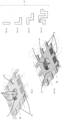
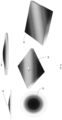
- the transducer 6 can have any shape. Some possible shapes are depicted in figures 5 - 8 .
- a first example of transducer is a rectangular MEMS 6a.
- the rectangular MEMS may be connected to the chamber 2, such as to wall 2a, in a single location 9 (see figure 6 ) or the same structure 6a can be connected to the wall 2a in more locations, such as 2 locations 9a, 9b of figure 5 . Any number of locations can be considered as well.
- a circular MEMS 6b is used as the transducer 6.
- the circular MEMS 6b may be connected to the chamber 2, such as to wall 2a, in a single location 9 (see figure 8 ) or the same structure 6b can be connected to the wall 2a in more locations, such as 2 locations 9a, 9b of figure 7 . Any number of locations can be considered as well.
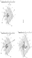
- Figures 9 and 10 refer only to the circular MEMS 6b, however the same principle can be applied to any shape of the transducer 6.
- the reflective element 6d of the transducer 6 may be connected directly to the chamber or a "stage" can be interposed in between.
- the sensor 1 may further comprise a damping and insulation structure 15 positioned between the main component 6c and the chamber 2. That is, the connection between the chamber 2 and the main component 6c is made via a damping and insulation structure 15.
- the role of the damping and insulation structure is to isolate the mechanical mode resonant at a given frequency in the transducer 6 from the external acoustic noise, which may degrade the signal by increasing the background noise and by creating locking issues (see below in the description of the interferometric detection method).
- the main component 6c is "isolated" by using a multi-stage structure (in Figs. 9 and 10 , single-stage transducers 6 are represented for simplicity).
- the damping and insulation structure 15 can be circular or polygonal symmetry (for example rectangular). The geometrical shape of the damping and insulating structure 15 may depend on the geometry of the main component 6c and from the manufacturing process.
- the damping and insulation structure 15 has a mass much bigger than the mass of the main component 6c.
- the damping and insulation structure connects the chamber to the main component 6c.
- the main component 6c is not otherwise connected to the chamber, that is, the main component 6c is connected to the chamber only via the damping and insulating structure 15.
- a large mass isolates the main component 6c, filtering out the low frequency noise.
- Various geometries for the suspension structures are possible (see point c below).
- the overall structure transducer + damping and insulation structure 15 has several mechanical modes, including at least one in which only the main component 6c moves. The frequency of this mode is far from the fundamental mode of the global structure. For this reason, it is possible to obtain a good mechanical insulation and to work with a good signal-to-noise ratio for the interferometer.
- the damping and insulation structure 15 surrounds the main component 6c.
- the connections between the damping and insulation structure 15 and the transducer are made via one or more first suspension structure, all named 16 in the figures.
- the first suspension structure is a special type of connection between the reflective element 6d and the chamber or the reflective element 6d and the damping and insulation structure 15.
- the first suspension structure comprises elongated elements (named also as suspensions) that reduce the length of the outer perimeter of the reflective element 6d in connection to the damping and insulation structure 15.
- Second suspension structure 18, similar to the first suspension structure 16, may also be present, to connect the damping and insulation structure 15 to the chamber 2.
- the suspension structures 16, 18 can have four different embodiments, depicted in figures 11 - 14 . In the following, only the first suspension structure is indicated in the figures, but the same shape applies also to the second suspension structure 18 as well.
- a beam shaped suspension 16 is shown. The suspension is substantially rod-like and it extends along a single direction for a given length.
- a L-shaped suspension 16 is shown. The suspension extends in a first direction for a first given length, then it makes a 90° turn and it extends for a second given length along a second direction.
- a Z-shaped suspension is shown.
- the suspension extends in a first direction for a first given length, then it makes a turn ⁇ 90° and it extends for a second given length along a second direction, it makes a second turn ⁇ 90° and it extends for a third length along a third direction, preferably parallel to the first direction.
- FIG 14 an S-shaped suspension is shown.
- the senor 1 comprises an interferometer 11 (visible in figures 2 and 3 ) and a second laser 10, called a reading laser.
- the interferometer 11 is used, together with the second laser 10, to detect the oscillation of the transducer 6 by interferometry.
- the second laser 10 is preferably a low power laser, for example a HeNe laser or a diode laser.
- the interferometer 11 is for example a Michelson type specifically designed to have balanced detection through laser beam polarization control.
- the detailed diagram of the interferometer is shown in the Figs. 2 and 3 .
- the interferometer 11 comprises a first polarizer 22. After being emitted, the second laser beam 12 impinges on the first polarizer 22, which acts as a filter for the initial polarization of the laser beam, so that the second laser beam 12 exiting the first polarizer has linear polarization, for example vertical.
- the beam exiting the first polarizer and detected in point P1 is linearly polarized.
- the movable mirror 19 is mounted on a moving stage (not shown) that enables its movements in the longitudinal direction with respect to the second split second beam (in this way it is possible to adjust the length of the second arm 14).
- the movements are actuated by the actuator 20, for example a piezoelectric transducer.
- the piezoelectric transducer allows fine movements (micrometric or sub-micrometric) of the movable mirror 19. In this way, the optical path defined by the second arm 14 can be varied.
- the sensor 1 further comprises an electronic board 40.
- the first and second detectors 30, 31 are mounted on the electronic board 40.
- the detectors 30, 31 emit signals that can be extracted and acquired.
- the signals of interest are the following: the signal from each detector (first and second detector) and the difference signal called D2-D1. The latter is the direct subtraction of the two photocurrents from the first and second detector 30, 31.
- the sensor 1 includes therefore a detection system 60 shown in figure 2 .
- the detection system 60 includes a digital acquisition system 61, for example an oscilloscope, to which the signal from one of the two detectors 30, 31 is sent to check the alignment; the signal from the other detector is sent to a lock-in amplifier 62 that demodulates it.
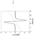
- the lock-in amplifier 62 gives at the output either the first-derivative (1 f demodulation) or the second-derivative (2f demodulation) signal of the molecular absorption of interest of the gas 3. This is the signal that is used in the spectroscopic analysis of the gas concentration.
- An example of such a demodulated signal is for example given in figure 15 .
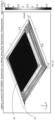
- Figure 23 shows further embodiments of the transducer 6, wherein the main component 6c comprises a first suspension structure 16 between the reflective element 6d and the chamber.
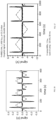
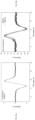
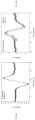
- Fig. 25a shows an acquisition in resonance (frequency modulation equal to the first cantilever resonance) meanwhile Fig. 25b shows an acquisition out of resonance, wherein:
- Fig. 26a shows an acquisition in resonance (frequency modulation equal to the third cantilever resonance) meanwhile Fig. 26b shows an acquisition out of resonance, wherein:
- the laser is scanned around the transition of N 2 O at 4526.86 nm (2209.523 cm -1 ) in a cell containing the gas sample at a fixed pressure (13 mbar in this case) for the whole time duration of the measurement.
- a rectangular silicon cantilever with size 2mm x 4mm and 10 ⁇ m depth has been used, and the third-order mechanical resonance has been chosen.
- the Locking point of the Michelson (differential signal) is set at zero.
- a gas sample on N 2 O (200 ppm concentration) in dry N2 has been used for the test.
- the second laser probing the Michelson interferometer is a HeNe laser emitting at 633 nm wavelength.
- the signal-to-noise ratio over a single acquisition of the graph in fig. 18 is 40, to be compared of the signal-to-noise ratio equal to 180 for a single acquisition of the graph of fig. 19 .
- the surface 70a is made up of Si and the surface 70b is made up of 3C-SiC.
- the surface 70b is etched through a mask prepared via photolithography using a suitable photoresist 72 to give the desired shape to the SiC layer.
- the Si surface 70a is etched through a mask 73.
- the remaining portions of the silicon carbide 70b are then covered by a reflective coating 74 so that the transducer 6 has a reflective surface.
- a silicon on insulator (SOI) wafer (75) has two surfaces: 75a is made up of a thin silicon device layer on a buried SiO 2 layer (75c); 70 b is a several hundred-micron thick silicon handle substrate.
- a SiO 2 layer 76 is deposited on top of the surface 75a.
- the SiO 2 layer 76, the surface 75a and the buried SiO 2 layer 75c are etched through a suitable photoresist mask layer 77.
- a conformal SiO 2 layer 78 is deposited to cover the surface and the vertical walls of the device layer 75a, and the top surface of the handle substrate 75b. The layer in the groves / on the top on the handle surface is 78a.
Landscapes
- Physics & Mathematics (AREA)
- Health & Medical Sciences (AREA)
- Life Sciences & Earth Sciences (AREA)
- Chemical & Material Sciences (AREA)
- Analytical Chemistry (AREA)
- Biochemistry (AREA)
- General Health & Medical Sciences (AREA)
- General Physics & Mathematics (AREA)
- Immunology (AREA)
- Pathology (AREA)
- Optics & Photonics (AREA)
- Engineering & Computer Science (AREA)
- Mathematical Physics (AREA)
- Theoretical Computer Science (AREA)
- Spectroscopy & Molecular Physics (AREA)
- Acoustics & Sound (AREA)
- Investigating Or Analysing Materials By Optical Means (AREA)
- Investigating Or Analyzing Materials By The Use Of Ultrasonic Waves (AREA)
Claims (11)
- Photoakustischer Sensor (1) zur spektroskopischen Gasdetektion, umfassend:• eine Kammer (2), die angepasst ist, um das zu analysierende Gas (3) zu enthalten;• eine Anregungslaserquelle (4), die angepasst ist, um einen modulierten Laserstrahl (5) zu emittieren, der von dem in der Kammer vorhandenen Gas absorbiert wird und eine Druckwelle erzeugt;• einen Wandler (6), wobei der Wandler innerhalb der Kammer angeordnet ist und angepasst ist, um durch die Druckwelle in Schwingungen versetzt zu werden, wobei der Wandler einen reflektierenden Abschnitt aufweist;• ein Interferometer (11) mit einem ersten und einem zweiten Arm und einem Ausgang, wobei der erste Arm (13) im Wandler endet und der zweite Arm (14) ein optisches Wegänderungselement und einen Aktuator (20) umfasst, der mit dem optischen Wegänderungselement verbunden ist, um den durch den zweiten Arm des Interferometers gebildeten optischen Weg zu ändern;• einen ersten polarisierenden Strahlteiler (24);• eine zweite Laserquelle (10) zum Ablesen des Interferometers, die angepasst ist, um einen zweiten Laserstrahl (12) zu emittieren, der auf den ersten polarisierenden Strahlteiler auftrifft, wobei der erste polarisierende Strahlteiler angepasst ist, um den zweiten Laserstrahl in den ersten und zweiten Arm des Interferometers zu teilen, so dass der geteilte Strahl (50), der sich im ersten Arm ausbreitet, durch den reflektierenden Teil des Wandlers zurückreflektiert wird, und der geteilte Strahl (51), der sich im zweiten Arm ausbreitet, durch das optische Wegänderungselement zurückreflektiert wird, so dass die resultierenden zurückreflektierten geteilten Strahlen (50', 51') im Interferometer interferieren;• einen zweiten polarisierenden Strahlteiler (29), der angepasst ist, um das interferierende Licht am Ausgang des Interferometers in zwei Strahlen (52, 53) zu teilen, die orthogonal polarisiert sind;• einen ersten Detektor (30), der angepasst ist, um einen der beiden orthogonal polarisierten Strahlen zu erfassen, die das Interferometer verlassen, und ein entsprechendes erstes Interferenzsignal zu emittieren;• einen zweiten Detektor (31), der angepasst ist, um den anderen der beiden orthogonal polarisierten Strahlen zu erfassen, die das Interferometer verlassen und ein entsprechendes zweites Interferenzsignal zu emittieren;• eine elektronische Schaltung, die eingerichtet ist, um ein Differenzsignal (D2-D1) zu erhalten, wobei das Differenzsignal eine Funktion der Differenz zwischen dem vom ersten Detektor emittierten Interferenzsignal und dem vom zweiten Detektor emittierten Interferenzsignal ist;• eine Rückkopplungsschleife, die angepasst ist, um die Bewegungen des Aktuators zu steuern, um den optischen Weg des zweiten Arms zu ändern, sodass das Differenzsignal während der Gaskonzentrationsmessungen auf einem gewünschten konstanten Wert gehalten wird.
- Sensor nach Anspruch 1, wobei der Wandler (6) aus Silizium, SiC, SIOz, Si3N4, einschließlich ihrer amorphen oder kristallinen Formen oder nicht-stöchiometrischen Formen, und aus Polymeren besteht, wobei der Wandler mit einem Metall, einem Metalloxid oder einer dielektrischen Mehrfachschicht beschichtet sein kann.
- Sensor nach Anspruch 1 oder 2, wobei der Wandler eine Hauptkomponente (6c) mit einem reflektierenden Element (6d) mit zumindest dem reflektierenden Abschnitt und eine Dämpfungs- und Isolationsstruktur (15) aufweist, die zwischen der Kammer (2) und der Hauptkomponente (6c) angeordnet ist, wobei die Hauptkomponente nur über die Dämpfungs- und Isolationsstruktur mit der Kammer verbunden ist.
- Sensor nach einem oder mehreren der vorhergehenden Ansprüche, wobei der gewünschte konstante Wert gleich Null ist.
- Sensor nach einem oder mehreren der vorhergehenden Ansprüche, wobei die Abmessung des Wandlers im Bereich von 10 µm bis 2 cm liegt.
- Verfahren zum Erfassen einer Gaskonzentration mittels eines photoakustischen Phänomens, wobei das Verfahren aufweist:• Vorsehen einer Kammer (2), in der sich ein Gas (3) befindet, dessen Konzentration gemessen werden soll;• Vorsehen eines Wandlers (6) in der Kammer, wobei der Wandler einen reflektierenden Abschnitt umfasst;• Erzeugen einer Druckwelle in der Kammer mittels eines modulierten Anregungslaserstrahls (5), der entsprechend dem photoakustischen Phänomen in die Kammer gerichtet wird, wobei die Druckwelle den Wandler in Schwingung versetzt;• Auftreffen eines zweiten Laserstrahls (12) auf den reflektierenden Teil des Wandlers;• Vorsehen eines Interferometers (11) mit einem ersten Arm (13), der in den Wandler mündet, und einem zweiten Arm (14), der in ein optisches Wegänderungselement mündet, das angepasst ist, um die Weglänge des zweiten Arms zu ändern;• Ausrichten eines zweiten Laserstrahls auf das Interferometer, wobei der zweite Laserstrahl einen ersten zurückreflektierten Strahl (50') bildet, wenn er vom Wandler reflektiert wird, und einen zweiten zurückreflektierten Strahl (51') bildet, wenn er vom optischen Wegänderungselement reflektiert wird;• Erzeugen einer Interferenz zwischen dem ersten und zweiten zurückreflektierten Strahl;• Teilen der interferierenden zurückreflektierten Strahlen in einen ersten und einen zweiten Interferenzstrahl (52, 53);• Polarisieren des ersten und/oder zweiten Interferenzstrahls, so dass ihre Polarisationsachsen zueinander senkrecht stehen;• Erfassen des ersten Interferenzstrahls (52) und zweiten Interferenzstrahls (53), wobei ein erstes und ein zweites Signal erzeugt wird;• Erzeugen eines Differenzsignals (D2-D1) als Funktion der Differenz zwischen dem ersten Signal und zweiten Signal;• Definieren eines Arbeitspunktwerts des Differenzsignals;• Anpassen der optischen Weglänge des zweiten Arms durch Betätigen des Aktuators, sodass das Differenzsignal während der Gaskonzentrationsmessung gleich dem Arbeitspunktwert bleibt.
- Verfahren nach Anspruch 6, das den Schritt des Versetzens des Wandlers (6) in Schwingungen mit einer Frequenz aufweist, die gleich der Resonanzfrequenz des Wandlers oder einer Resonanz höherer Ordnung ist.
- Verfahren nach Anspruch 6, das den Schritt des Versetzens des Wandlers (6) in Schwingungen mit einer Frequenz aufweist, die außerhalb der Resonanzfrequenzen des Wandlers liegt.
- Verfahren nach einem oder mehreren der Ansprüche 6 bis 8, das den Schritt des Erhaltens der Gaskonzentration aus dem Schritt des Erfassens des ersten Interferenzstrahls (52) oder aus dem Schritt des Erfassens des zweiten Interferenzstrahls (53) aufweist, wenn die Frequenz der Bewegungen des optischen Wegänderungselements viel langsamer ist als die Modulationsfrequenz des Anregungslasers (4).
- Verfahren nach einem oder mehreren der Ansprüche 6 bis 8, das den Schritt aufweist:• Senden eines Signals an das optische Wegänderungselement, sodass das Differenzsignal (D2-D1) gleich dem Arbeitspunktwert bleibt;• Erhalten der Gaskonzentration aus dem an das optische Wegänderungselement gesendete Signal, wenn die Frequenz der Bewegungen des optischen Wegänderungselements in der gleichen Größenordnung liegt wie die Modulationsfrequenz des Anregungslasers (4).
- Verfahren nach einem oder mehreren der Ansprüche 6 bis 10, wobei der Schritt des Auftreffens mit einem modulierten Anregungslaserstrahl (5) aufweist:• Betreiben eines Anregungslasers (4) bei vorgegebenem Strom und Temperatur,• Hinzufügen einer schnellen Modulation bei der vorgegebenen Frequenz zum Antriebsstrom und,• Hinzufügen einer langsamen Modulation mit einer Frequenz, die viel langsamer ist als die vorgegebene Frequenz, zum Strom, um die optische Anregungslaserfrequenz über den molekularen Übergang zu scannen.
Applications Claiming Priority (2)
| Application Number | Priority Date | Filing Date | Title |
|---|---|---|---|
| IT102021000033143A IT202100033143A1 (it) | 2021-12-30 | 2021-12-30 | Sensore di spettroscopia fotoacustica per il rilevamento di gas traccia e metodo per il rilevamento di gas traccia |
| PCT/EP2022/087976 WO2023126455A1 (en) | 2021-12-30 | 2022-12-28 | Photoacoustic spectroscopy sensor for trace gas detection and method for trace gas detection |
Publications (3)
| Publication Number | Publication Date |
|---|---|
| EP4457500A1 EP4457500A1 (de) | 2024-11-06 |
| EP4457500B1 true EP4457500B1 (de) | 2025-07-02 |
| EP4457500C0 EP4457500C0 (de) | 2025-07-02 |
Family
ID=80933740
Family Applications (1)
| Application Number | Title | Priority Date | Filing Date |
|---|---|---|---|
| EP22844526.8A Active EP4457500B1 (de) | 2021-12-30 | 2022-12-28 | Photoakustischer spektroskopiesensor zur spurengasdetektion und verfahren zur spurengasdetektion |
Country Status (4)
| Country | Link |
|---|---|
| US (1) | US20250060306A1 (de) |
| EP (1) | EP4457500B1 (de) |
| IT (1) | IT202100033143A1 (de) |
| WO (1) | WO2023126455A1 (de) |
Families Citing this family (1)
| Publication number | Priority date | Publication date | Assignee | Title |
|---|---|---|---|---|
| FR3162508A1 (fr) | 2024-05-22 | 2025-11-28 | Centralesupelec | Système de mesure d’une déformation photo-induite d’un échantillon |
Family Cites Families (5)
| Publication number | Priority date | Publication date | Assignee | Title |
|---|---|---|---|---|
| CA1287388C (en) * | 1988-04-29 | 1991-08-06 | Jean-Pierre Monchalin | Broadband optical detection of transient motion from a scattering surface |
| FI116859B (fi) | 2002-09-30 | 2006-03-15 | Noveltech Solutions Ltd | Fotoakustinen detektori |
| FI20105187A0 (fi) | 2010-02-25 | 2010-02-25 | Gasera Ltd | Liikuteltavan peilin tukirakenne, menetelmä liikuteltavan peilin kallistelun vähentämiseksi ja interferometri |
| GB2492841A (en) * | 2011-07-15 | 2013-01-16 | Secr Defence | Laser photoacoustic spectroscopy using a plurality of tuneable lasers |
| EP3356798B1 (de) | 2015-09-30 | 2019-09-04 | CNR - Consiglio Nazionale Delle Ricerche | Verfahren zur messung der konzentration von spurengasen durch scar spektroskopie |
-
2021
- 2021-12-30 IT IT102021000033143A patent/IT202100033143A1/it unknown
-
2022
- 2022-12-28 US US18/723,954 patent/US20250060306A1/en active Pending
- 2022-12-28 EP EP22844526.8A patent/EP4457500B1/de active Active
- 2022-12-28 WO PCT/EP2022/087976 patent/WO2023126455A1/en not_active Ceased
Also Published As
| Publication number | Publication date |
|---|---|
| IT202100033143A1 (it) | 2023-06-30 |
| WO2023126455A1 (en) | 2023-07-06 |
| US20250060306A1 (en) | 2025-02-20 |
| EP4457500A1 (de) | 2024-11-06 |
| EP4457500C0 (de) | 2025-07-02 |
Similar Documents
| Publication | Publication Date | Title |
|---|---|---|
| Zheng et al. | Quartz-enhanced photoacoustic spectroscopy employing pilot line manufactured custom tuning forks | |
| Fu et al. | Small-volume highly-sensitive all-optical gas sensor using non-resonant photoacoustic spectroscopy with dual silicon cantilever optical microphones | |
| RU2716146C1 (ru) | Фототермическое интерферометрическое устройство и соответствующий способ | |
| Yin et al. | Cantilever-enhanced photoacoustic spectroscopy for gas sensing: A comparison of different displacement detection methods | |
| Pan et al. | Miniaturized and highly-sensitive fiber-optic photoacoustic gas sensor based on an integrated tuning fork by mechanical processing with dual-prong differential measurement | |
| EP3710811B1 (de) | Verfahren zur messung des brechungsindex einer probe unter verwendung von oberflächenplasmon-polaritonen | |
| Li et al. | Miniature optical fiber photoacoustic spectroscopy gas sensor based on a 3D micro-printed planar-spiral spring optomechanical resonator | |
| CN112098737A (zh) | 一种微波电场强度的测量方法及装置 | |
| Pelini et al. | New silicon-based micro-electro-mechanical systems for photo-acoustic trace-gas detection | |
| Ye et al. | Ultrastable optical frequency reference at 1.064/spl mu/m using a C/sub 2/HD molecular overtone transition | |
| US20240319082A1 (en) | Optical device, spectroscopic device, and spectroscopic method | |
| US20170268930A1 (en) | Spectroscopic Apparatus and Method | |
| US12442686B2 (en) | Optical device and spectroscopy apparatus | |
| Breguet et al. | Photoacoustic detection of trace gases with an optical microphone | |
| EP4457500B1 (de) | Photoakustischer spektroskopiesensor zur spurengasdetektion und verfahren zur spurengasdetektion | |
| Lv et al. | Application of piezoelectric transducers in photoacoustic spectroscopy for trace gas analysis | |
| US4836675A (en) | Apparatus and method for detecting rotation rate and direction of rotation and providing cavity length control in multioscillator ring laser gyroscopes | |
| US6747742B1 (en) | Microspectrometer based on a tunable fabry-perot interferometer and microsphere cavities | |
| Wei et al. | All-optical cantilever-enhanced photoacoustic spectroscopy in the open environment | |
| US12546708B2 (en) | Optical device and spectroscopic device | |
| Jiang et al. | Membraneless optical microphone based photoacoustic spectroscopy for trace gas detection | |
| Tortschanoff et al. | Improved MOEMS-based ultra-rapid Fourier transform infrared spectrometer | |
| Wang et al. | Doubly resonant photoacoustic spectroscopy: Ultra-high sensitivity meets ultra-wide dynamic range | |
| Patimisco et al. | Comparison between interferometric and piezoelectric readout of tuning fork vibrations in quartz-enhanced photoacoustic spectroscopy | |
| Hahtela et al. | Position measurement of a cavity mirror using polarization spectroscopy |
Legal Events
| Date | Code | Title | Description |
|---|---|---|---|
| STAA | Information on the status of an ep patent application or granted ep patent |
Free format text: STATUS: UNKNOWN |
|
| STAA | Information on the status of an ep patent application or granted ep patent |
Free format text: STATUS: THE INTERNATIONAL PUBLICATION HAS BEEN MADE |
|
| PUAI | Public reference made under article 153(3) epc to a published international application that has entered the european phase |
Free format text: ORIGINAL CODE: 0009012 |
|
| STAA | Information on the status of an ep patent application or granted ep patent |
Free format text: STATUS: REQUEST FOR EXAMINATION WAS MADE |
|
| 17P | Request for examination filed |
Effective date: 20240716 |
|
| AK | Designated contracting states |
Kind code of ref document: A1 Designated state(s): AL AT BE BG CH CY CZ DE DK EE ES FI FR GB GR HR HU IE IS IT LI LT LU LV MC ME MK MT NL NO PL PT RO RS SE SI SK SM TR |
|
| GRAP | Despatch of communication of intention to grant a patent |
Free format text: ORIGINAL CODE: EPIDOSNIGR1 |
|
| STAA | Information on the status of an ep patent application or granted ep patent |
Free format text: STATUS: GRANT OF PATENT IS INTENDED |
|
| RIC1 | Information provided on ipc code assigned before grant |
Ipc: G01N 29/02 20060101ALI20250107BHEP Ipc: G01N 29/24 20060101ALI20250107BHEP Ipc: G01N 21/27 20060101ALI20250107BHEP Ipc: G01N 21/17 20060101AFI20250107BHEP |
|
| INTG | Intention to grant announced |
Effective date: 20250122 |
|
| DAV | Request for validation of the european patent (deleted) | ||
| DAX | Request for extension of the european patent (deleted) | ||
| GRAS | Grant fee paid |
Free format text: ORIGINAL CODE: EPIDOSNIGR3 |
|
| GRAA | (expected) grant |
Free format text: ORIGINAL CODE: 0009210 |
|
| STAA | Information on the status of an ep patent application or granted ep patent |
Free format text: STATUS: THE PATENT HAS BEEN GRANTED |
|
| AK | Designated contracting states |
Kind code of ref document: B1 Designated state(s): AL AT BE BG CH CY CZ DE DK EE ES FI FR GB GR HR HU IE IS IT LI LT LU LV MC ME MK MT NL NO PL PT RO RS SE SI SK SM TR |
|
| REG | Reference to a national code |
Ref country code: GB Ref legal event code: FG4D |
|
| REG | Reference to a national code |
Ref country code: CH Ref legal event code: EP |
|
| REG | Reference to a national code |
Ref country code: DE Ref legal event code: R096 Ref document number: 602022017093 Country of ref document: DE |
|
| REG | Reference to a national code |
Ref country code: IE Ref legal event code: FG4D |
|
| U01 | Request for unitary effect filed |
Effective date: 20250725 |
|
| U07 | Unitary effect registered |
Designated state(s): AT BE BG DE DK EE FI FR IT LT LU LV MT NL PT RO SE SI Effective date: 20250801 |
|
| U20 | Renewal fee for the european patent with unitary effect paid |
Year of fee payment: 4 Effective date: 20251204 |
|
| PG25 | Lapsed in a contracting state [announced via postgrant information from national office to epo] |
Ref country code: IS Free format text: LAPSE BECAUSE OF FAILURE TO SUBMIT A TRANSLATION OF THE DESCRIPTION OR TO PAY THE FEE WITHIN THE PRESCRIBED TIME-LIMIT Effective date: 20251102 |
|
| PG25 | Lapsed in a contracting state [announced via postgrant information from national office to epo] |
Ref country code: NO Free format text: LAPSE BECAUSE OF FAILURE TO SUBMIT A TRANSLATION OF THE DESCRIPTION OR TO PAY THE FEE WITHIN THE PRESCRIBED TIME-LIMIT Effective date: 20251002 |
|
| PG25 | Lapsed in a contracting state [announced via postgrant information from national office to epo] |
Ref country code: HR Free format text: LAPSE BECAUSE OF FAILURE TO SUBMIT A TRANSLATION OF THE DESCRIPTION OR TO PAY THE FEE WITHIN THE PRESCRIBED TIME-LIMIT Effective date: 20250702 |
|
| PG25 | Lapsed in a contracting state [announced via postgrant information from national office to epo] |
Ref country code: GR Free format text: LAPSE BECAUSE OF FAILURE TO SUBMIT A TRANSLATION OF THE DESCRIPTION OR TO PAY THE FEE WITHIN THE PRESCRIBED TIME-LIMIT Effective date: 20251003 |
|
| PG25 | Lapsed in a contracting state [announced via postgrant information from national office to epo] |
Ref country code: CZ Free format text: LAPSE BECAUSE OF FAILURE TO SUBMIT A TRANSLATION OF THE DESCRIPTION OR TO PAY THE FEE WITHIN THE PRESCRIBED TIME-LIMIT Effective date: 20250702 |
|
| PG25 | Lapsed in a contracting state [announced via postgrant information from national office to epo] |
Ref country code: PL Free format text: LAPSE BECAUSE OF FAILURE TO SUBMIT A TRANSLATION OF THE DESCRIPTION OR TO PAY THE FEE WITHIN THE PRESCRIBED TIME-LIMIT Effective date: 20250702 |
|
| PG25 | Lapsed in a contracting state [announced via postgrant information from national office to epo] |
Ref country code: RS Free format text: LAPSE BECAUSE OF FAILURE TO SUBMIT A TRANSLATION OF THE DESCRIPTION OR TO PAY THE FEE WITHIN THE PRESCRIBED TIME-LIMIT Effective date: 20251002 |
|
| PG25 | Lapsed in a contracting state [announced via postgrant information from national office to epo] |
Ref country code: ES Free format text: LAPSE BECAUSE OF FAILURE TO SUBMIT A TRANSLATION OF THE DESCRIPTION OR TO PAY THE FEE WITHIN THE PRESCRIBED TIME-LIMIT Effective date: 20250702 |
|
| PG25 | Lapsed in a contracting state [announced via postgrant information from national office to epo] |
Ref country code: SM Free format text: LAPSE BECAUSE OF FAILURE TO SUBMIT A TRANSLATION OF THE DESCRIPTION OR TO PAY THE FEE WITHIN THE PRESCRIBED TIME-LIMIT Effective date: 20250702 |
|
| PG25 | Lapsed in a contracting state [announced via postgrant information from national office to epo] |
Ref country code: SK Free format text: LAPSE BECAUSE OF FAILURE TO SUBMIT A TRANSLATION OF THE DESCRIPTION OR TO PAY THE FEE WITHIN THE PRESCRIBED TIME-LIMIT Effective date: 20250702 |