EP4457067B1 - Schneidverfahren - Google Patents
Schneidverfahren Download PDFInfo
- Publication number
- EP4457067B1 EP4457067B1 EP22844675.3A EP22844675A EP4457067B1 EP 4457067 B1 EP4457067 B1 EP 4457067B1 EP 22844675 A EP22844675 A EP 22844675A EP 4457067 B1 EP4457067 B1 EP 4457067B1
- Authority
- EP
- European Patent Office
- Prior art keywords
- blade
- slab
- cutting
- inclination
- slabs
- Prior art date
- Legal status (The legal status is an assumption and is not a legal conclusion. Google has not performed a legal analysis and makes no representation as to the accuracy of the status listed.)
- Active
Links
Images


Classifications
-
- B—PERFORMING OPERATIONS; TRANSPORTING
- B28—WORKING CEMENT, CLAY, OR STONE
- B28D—WORKING STONE OR STONE-LIKE MATERIALS
- B28D1/00—Working stone or stone-like materials, e.g. brick, concrete or glass, not provided for elsewhere; Machines, devices, tools therefor
- B28D1/02—Working stone or stone-like materials, e.g. brick, concrete or glass, not provided for elsewhere; Machines, devices, tools therefor by sawing
- B28D1/04—Working stone or stone-like materials, e.g. brick, concrete or glass, not provided for elsewhere; Machines, devices, tools therefor by sawing with circular or cylindrical saw-blades or saw-discs
- B28D1/048—Working stone or stone-like materials, e.g. brick, concrete or glass, not provided for elsewhere; Machines, devices, tools therefor by sawing with circular or cylindrical saw-blades or saw-discs with a plurality of saw blades
-
- B—PERFORMING OPERATIONS; TRANSPORTING
- B23—MACHINE TOOLS; METAL-WORKING NOT OTHERWISE PROVIDED FOR
- B23D—PLANING; SLOTTING; SHEARING; BROACHING; SAWING; FILING; SCRAPING; LIKE OPERATIONS FOR WORKING METAL BY REMOVING MATERIAL, NOT OTHERWISE PROVIDED FOR
- B23D45/00—Sawing machines or sawing devices with circular saw blades or with friction saw discs
- B23D45/10—Sawing machines or sawing devices with circular saw blades or with friction saw discs with a plurality of circular saw blades
- B23D45/105—Sawing machines or sawing devices with circular saw blades or with friction saw discs with a plurality of circular saw blades operating within the same plane
Definitions
- the present invention generally relates to the technical field of machining stone and/or ceramic materials and particularly relates to a method for cutting slabs using a cutting head.
- machine tools comprising a gantry structure suitable to delimit a work area and at least one horizontal beam on which there is slidably mounted a head for processing the slabs.
- machining operations carried out with such machines are for example cutting, smoothing, contouring, chamfering or the like, and they may require handling, loading/unloading and/or transfer of the products being machined from one area to another of the work area.
- the machine tool comprises a carriage slidable on the main beam and a cutting head movable above the slab with an electro-spindle to which there is rotatably associated a blade-equipped cutting tool.
- the second slab is spaced from the first slab by a value proportional to the diameter of the blade, so as to prevent the blade from interacting with the transversal peripheral edge of the second slab arranged adjacent to the first slab after cutting the first slab.
- the cutting head supports at least one first and one second blade which are substantially vertical and aligned, and having respective centres spaced by a predetermined distance
- the distance between the first and the second slab is excessive, resulting in the increase of machining times and decrease in the number of slabs arranged adjacent to each other during machining.
- WO2017002035 discloses an apparatus and a method for cutting porcelain slabs or the like, which provides for a cutting head arranged above a plane for supporting a slab.
- the head is provided with a plurality of rotary tools associated with a carriage movable along a horizontal axis and means for the vertical movement of the tools independently from each other.
- the method for cutting a slab using such apparatus provides a first step in which the carriage is moved towards the slab to be machined with only one first tool lowered so as to interact with the slab.
- the first tool starts to engrave the slab and, subsequently, the second tool is lowered upon exceeding the entry point on the slab. Lastly, the first tool is raised before it exits from the final part of the slab.
- EP3842172 discloses an apparatus provided with a cutting head equipped with a first and a second disc-shaped blade aligned with respect to each other along a cutting direction and arranged above a work plane suitable to support at least one slab.
- the cutting head comprises means for the vertical movement of each blade to lift each blade with respect to the slab when the blade finishes to cut the slab.
- a first known drawback of such solutions lies in the fact that the means for the vertical movement act independently on each blade of the cutting head with ensuing increase in the costs for manufacturing the cutting head.
- EP3603913 discloses a method of cutting slabs made of stone and/or ceramic material with a cutting head having a tool-holder frame mounted on a carriage movable above the slabs, wherein said frame supports at least one first and one second blade which are substantially vertical and mutually aligned along a longitudinal cutting direction and have respective centres spaced apart by a predetermined distance, said frame being hinged to said carriage by means of a substantially horizontal pin so as to allow the oscillation of said frame and vary the relative height of said blades and the respective cutting depth thereof, the method comprising the following steps:
- the object of the present invention is to solve the technical problem by providing a cutting head which allows to machine several slabs arranged adjacent to each other in which the blades do not damage the subsequent slab after cutting, and at the same time it allows to reduce the distance between the slabs.
- the object of the present invention is to solve the aforementioned problem by providing a method for cutting slabs made of stone and/or ceramic material which is highly effective and cost-effective.
- a particular object of the present invention is to provide a cutting method of the type indicated above which allows to reduce the distance between two slabs arranged adjacent to each other when cutting them.
- Another particular object of the present invention is to provide a cutting method of the type indicated above which allows to carry out discontinuous or staggered cuts on one or more adjacent slabs along a horizontal axis, preventing the blade from interacting with the transversal peripheral edge of a second slab arranged adjacent to the first slab after cutting the first slab.
- a further object of the present invention is to provide a cutting method of the type indicated above which makes the operations for pre-cutting and cutting two adjacent slabs particularly quick and simple.
- Another object of the present invention is to provide a cutting method of the type indicated above which allows to carry out the pre-cutting and cutting of the slab in a single phase.
- a further object of the present invention is to provide a cutting method of the type indicated above which allow to reduce downtime between the discontinuous cut of one slab and the subsequent one, increasing the overall productivity.
- a further object of the present invention is to provide a cutting method of the type indicated above which allows to reduce the overall set-up and installation times.
- the method provides the cutting of slabs made of stone and/or ceramic material using a cutting head having a tool-holder frame mounted on a carriage movable above the slabs along three cartesian axes, wherein the frame supports at least one first and one second blade which are substantially vertical and aligned, and having respective centres spaced apart by a predetermined distance.
- the frame is hinged to the carriage by means of a substantially horizontal pin so as to allow the oscillation of the frame and vary the relative height of the blades and the cutting depth thereof.
- the method comprises the following steps a) first inclination of the frame by a first predetermined angle with respect to a first slab to be cut so that the first blade is lower than the second blade by a first relative height, b) pre-cutting the first slab using the first blade, c) second inclination of the frame by a second predetermined angle with respect to the first slab so that the first blade is higher than the second blade by a second relative height, d) cutting the first slab using the second blade and e) third inclination of the frame by a third predetermined angle with respect to first slab so that the first blade is higher than the second blade by a third relative height greater than the second relative height so as to prevent the first blade from interacting with a second slab arranged adjacent to the first slab when cutting the first slab in step d).
- the cutting head 1 may be applied to a multi-axial machine tool 2 for cutting or shaping also slabs L made of stone material, such as stone, marble, granite, stony or concrete conglomerates, and to obtain a plurality of suitably shaped portions L', L".
- slabs L made of stone material, such as stone, marble, granite, stony or concrete conglomerates, and to obtain a plurality of suitably shaped portions L', L".
- the multi-axial machine tool 2 may comprise at least one substantially horizontal main beam 3 movable along first longitudinal guide means 4 anchored to the ground, as described in the patent application EP2983879 owned by the applicant.
- the machine 2 may comprise one or more cutting heads 1 mounted on the secondary beam 5 and slidably movable along second guide means 6 associated with the secondary beam 5 to carry out cuts along directions parallel to a longitudinal cutting direction D in a single phase, as described below.
- the secondary beam 5 may be mounted below the main beam 3 and can be rotatably coupled to the latter using third guide means 7 to rotate around a substantially vertical axis Y and to vary the direction of the common cutting direction D.
- the slabs L may comprise a substantially flat upper surface L A facing upwards and facing the cutting head 1, a substantially flat lower surface L B resting on the work plane 8, and a maximum thickness s having predetermined and substantially constant dimensions.
- the cutting head 1 comprises a carriage 9 movable above the slabs L along a first transversal axis X 1 and along a second longitudinal axis X 2 by means of respective first 4 and second guide means 6.
- the carriage 9 comprises movement means 10 which are substantially vertical and can be coupled to the main beam 3, or to the secondary beam 5, of the machine tool 2 on which the cutting head 1 is mounted so as to move it along a vertical axis Z. Therefore, the carriage 9 is movable above the slabs L along the three cartesian axes X 1 , X 2 , Z.
- the cutting head 1 comprises a tool-holder frame 11 mounted on the carriage 9 and that supports at least one first 12 and one second blade 13 which are substantially vertical and mutually aligned along the longitudinal cutting direction D, and having respective centres C 1 , C 2 for coupling to respective electro-spindles 14, 15 spaced apart by a predetermined distance V.
- the first 12 and the second blade 13 have substantially equal diameters.
- the frame 11 is hinged to the carriage 9 by means of a substantially horizontal pin 16 so as to allow the oscillation of the frame 11 and vary the relative height h R of the blades 12, 13 and the respective cutting depth h 1 , h 2 thereof.
- the pin 16 may be positioned in proximity of a first longitudinal end of the frame 11 and above the second blade 13 so that the latter has a substantially constant height position in response to the oscillation of the frame 11, therefore solely varying the height of the first blade 12.
- the pin 16 may be in intermediate position with respect to the longitudinal ends of the frame 11, so that such intermediate position has a substantially constant height position in response to the oscillation of the frame 11.
- the first cutting blade 12 is configured to carry out a pre-cutting T 1 in the slab L having a pre-cutting depth h 1 with depth which can be adjusted and smaller than the thickness s of the slab L, while the second cutting blade 13 is configured to carry out the final cutting T 2 of the slab L and therefore with a cutting depth h 2 with depth which can be adjusted and equal to or greater than the thickness s of the slab L.
- the slabs L may be arranged along the work plane 8 side by side and transversely spaced apart by a predetermined value W, so as to allow the discontinuous cutting thereof, or carry out the horizontally staggered cuts, as shown in FIG. 3 .
- the cutting method according to the invention is carried out by the cutting head 1 so as to prevent the distance W between the slabs L from being excessive.
- Such excessive distance W is schematically shown in FIG. 4 .
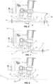
- the method according to the invention comprises a first step a) of first inclination of the frame 11 by a first predetermined angle ⁇ 1 with respect to a first slab L 1 to be cut so that the first blade 12 is lower than the second blade 13 by a first relative height h R1 , as shown in FIG. 6 .
- the method provides a step b) of pre-cutting the first slab L 1 using the first blade 12, as shown in FIGS. 7 and 8 .
- step a 1 of first lowering of the carriage 9 with respect to the work plane 8 so as to allow the first blade 12 to interact with the first slab L 1 and carry out the pre-cutting T 1 , as shown in FIG. 7 .
- the first lowering of the carriage 9 occurs in a substantially vertical direction Q.
- the step a 1 ) of first lowering is carried out when the centre C 1 of the first blade 12 is positioned at the first transversal peripheral edge B A of the first slab L 1 .
- the first slab L 1 is pre-cut by the first blade 12 for a pre-cutting depth h 1 which corresponds to 50% of the thickness s 1 of the first slab L 1 .
- the second blade 13 does not interact with the first slab L 1 and does not even interact with a possible slab L 0 positioned preceding the first slab L 1 along the cutting direction D.
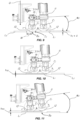
- step c) of second inclination is at least partially carried out during step b) of pre-cutting so that the movement of the cutting head 1 along the common cutting direction D is not interrupted.
- step c 1 of second lowering of the carriage 9 with respect to the work plane 8 so as to allow the second blade 13 to interact with the first slab L 1 maintaining constant the pre-cutting depth h 1 of the first blade 12.
- the second lowering of the carriage 9 occurs in a substantially vertical direction Q.
- the steps c) of second inclination and c 1 ) of second lowering are carried out at the same time and when the centre C 2 of the second blade 13 is positioned at the first transversal peripheral edge B A of the first slab L 1 .
- the first slab L 1 is cut by the second blade 13 for a cutting depth h 2 which corresponds to 100% of the thickness s 1 of the first slab L 1 .
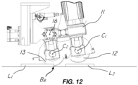
- the method according to the invention provides a step e) of third inclination of the frame 11 by a third predetermined angle ⁇ 3 with respect to the first slab L 1 so that the first blade 12 is higher than the second blade 13 by a third relative height h R3 greater than the second relative height h R2 .
- the step e) of third inclination is at least partially carried out during said step d) of cutting and when the centre C 1 of the first blade 12 is positioned at the second transversal peripheral edge B B of the first slab L 1 .
- the second blade 13 interacts with the first slab L 1 maintaining constant the cutting depth h 2 of the second blade 13.
- the cutting of the first slab L 1 during the step d) may end when the centre C 2 of the second blade 13 is positioned at the second transversal peripheral edge B B of the first slab L 1 , as better shown in FIG. 12 .
- step e) allows to prevent the first blade 12 from interacting with a second slab L 2 arranged adjacent to the first slab L 1 when cutting the first slab L 1 in step d).
- steps a)-e) of the method according to the invention allow to carry out discontinuous or staggered cuts of two or more adjacent slabs along a horizontal axis, preventing the first blade 12 from interacting with the transversal peripheral edge B A of a second slab L 2 after cutting the first slab L 1 by means of the second blade 13.
- the method for cutting slabs arranged adjacent to each other using a cutting head 1 of the type described above allows to space the first slab L 1 from the second slab L 2 by the same distance W that would be obtained by cutting the slabs L 1 , L 2 using a cutting head provided with only one cutting blade.
- the cutting method according to the invention achieves the pre-established objects and in particular it allows to reduce the distance between two slabs arranged adjacent to each other when cutting them.
- the present invention is industrially applicable because it can be produced in industrial scale by industries belonging to the field of machining stone and/or ceramic materials.
Landscapes
- Engineering & Computer Science (AREA)
- Mechanical Engineering (AREA)
- Mining & Mineral Resources (AREA)
- Processing Of Stones Or Stones Resemblance Materials (AREA)
- Mechanical Treatment Of Semiconductor (AREA)
Claims (12)
- Verfahren zum Schneiden von Platten (L) aus Stein und/oder keramischem Material mit einem Schneidkopf (1), der einen Werkzeughalterahmen (11) aufweist, der auf einem Schlitten (9) montiert ist, der oberhalb der Platten (L) beweglich ist, wobei der Rahmen (11) mindestens eine erste (12) und eine zweite Klinge (13) trägt, die im Wesentlichen vertikal und entlang einer Längsschneidrichtung (D) zueinander ausgerichtet sind und jeweilige Mittelpunkte (C1, C2) aufweisen, die um einen vorbestimmten Abstand (V) voneinander beabstandet sind, wobei der Rahmen (11) mittels eines im Wesentlichen horizontalen Stifts (16) an dem Schlitten (9) angelenkt ist, um die Schwingung des Rahmens (11) zu ermöglichen und die relative Höhe (hR) der Klingen (12, 13) und deren jeweilige Schnitttiefe (h1, h2) zu verändern, wobei das Verfahren die folgenden Schritte umfasst:a) erste Neigung des Rahmens (11) um einen ersten vorbestimmten Winkel (α1) in Bezug auf eine erste zu schneidende Platte (L1), so dass das erste Messer (12) um eine erste relative Höhe (hR1) niedriger ist als das zweite Messer (13)b) Vorschneiden der ersten Platte (L1) unter Verwendung des ersten Messers (12);c) zweite Neigung des Rahmens (11) um einen zweiten vorbestimmten Winkel (α2) in Bezug auf die erste Platte (L1), so dass die erste Klinge (12) um eine zweite relative Höhe (hR2) höher ist als die zweite Klinge (13);d) Schneiden der ersten Platte (L1) mit dem zweiten Messer (13);e) dritte Neigung des Rahmens (11) um einen dritten vorbestimmten Winkel (α3) in Bezug auf die erste Platte (L1), so dass die erste Klinge (12) um eine dritte relative Höhe (hR3) höher ist als die zweite Klinge (13), die größer ist als die zweite relative Höhe (hR2), um zu verhindern, dass die erste Klinge (12) mit einer zweiten Platte (L2) neben der ersten Platte (L1) zusammenwirkt.
- Verfahren nach Anspruch 1, wobei die erste (hR1), zweite (hR2) und dritte relative Höhe (hR3) unter Verwendung der Formel hR=V x sinα ± K berechnet werden, wobei K eine vorbestimmte Konstante ist, die sich auf die Dicke (s1, s2) der bearbeiteten Platten (L1, L2) bezieht.
- Verfahren nach Anspruch 2, wobei die vorbestimmte Konstante (K) ein numerischer Wert zwischen 0 und s±Ks ist, wobei Ks ein vorbestimmter Sicherheitskoeffizient mit einem Wert größer als 0 ist, um zu verhindern, dass die erste (12) und die zweite Klinge (13) mit den zu bearbeitenden Platten (L1, L2) in Wechselwirkung treten.
- Verfahren nach Anspruch 1, wobei vor dem Schritt b) des Vorschneidens ein Schritt a1) des ersten Absenkens des Schlittens (9) in Bezug auf die Arbeitsebene (8), auf der die Platten (L1, L2) angeordnet sind, vorgesehen ist, damit die erste Klinge (12) mit der ersten Platte (L1) zusammenwirken kann.
- Verfahren nach Anspruch 4, wobei der Schritt a1) des ersten Absenkens durchgeführt wird, wenn die Mitte (C1) der ersten Klinge (12) an der ersten Querumfangskante (BA) der ersten Platte (L1) positioniert ist.
- Verfahren nach Anspruch 1, wobei der Schritt c) des zweiten Neigens zumindest teilweise während des Schritts b) des Vorschneidens ausgeführt wird.
- Verfahren nach Anspruch 1, wobei während des Schritts c) der zweiten Neigung ein Schritt c1) des zweiten Absenkens des Schlittens (9) in Bezug auf die Arbeitsebene (8), auf der die Platten (L1, L2) angeordnet sind, vorgesehen ist, um es dem zweiten Messer (13) zu ermöglichen, mit der ersten Platte (L1) zusammenzuwirken, wobei die Vorschneidetiefe (h1) des ersten Messers (12) konstant gehalten wird.
- Verfahren nach Anspruch 6, wobei die Schritte c) der zweiten Neigung und c1) des zweiten Absenkens zur gleichen Zeit und dann ausgeführt werden, wenn die Mitte (C2) des zweiten Messers (13) an der ersten transversalen Umfangskante (BA) der ersten Platte (L1) positioniert ist.
- Verfahren nach Anspruch 1, wobei der Schritt e) der dritten Neigung zumindest teilweise während des Schritts d) des Schneidens ausgeführt wird.
- Verfahren nach Anspruch 1, wobei der Schritt e) der dritten Neigung durchgeführt wird, wenn die Mitte (C1) der ersten Klinge (12) an der zweiten transversalen Umfangskante (BB) der ersten Platte (L1) positioniert ist.
- Verfahren nach Anspruch 1, wobei während des Schritts e) der dritten Neigung die zweite Klinge (13) mit der ersten Platte (L1) zusammenwirkt und die Schnitttiefe (h2) der zweiten Klinge (13) konstant hält.
- Verfahren nach Anspruch 1, wobei die erste (12) und die zweite Klinge (13) im Wesentlichen gleiche Durchmesser haben.
Priority Applications (1)
| Application Number | Priority Date | Filing Date | Title |
|---|---|---|---|
| SM20250250T SMT202500250T1 (it) | 2021-12-28 | 2022-12-20 | Metodo di taglio |
Applications Claiming Priority (2)
| Application Number | Priority Date | Filing Date | Title |
|---|---|---|---|
| IT102021000032804A IT202100032804A1 (it) | 2021-12-28 | 2021-12-28 | Metodo di taglio |
| PCT/IB2022/062523 WO2023126767A1 (en) | 2021-12-28 | 2022-12-20 | Cutting method |
Publications (2)
| Publication Number | Publication Date |
|---|---|
| EP4457067A1 EP4457067A1 (de) | 2024-11-06 |
| EP4457067B1 true EP4457067B1 (de) | 2025-04-09 |
Family
ID=80685243
Family Applications (1)
| Application Number | Title | Priority Date | Filing Date |
|---|---|---|---|
| EP22844675.3A Active EP4457067B1 (de) | 2021-12-28 | 2022-12-20 | Schneidverfahren |
Country Status (7)
| Country | Link |
|---|---|
| EP (1) | EP4457067B1 (de) |
| ES (1) | ES3026748T3 (de) |
| IT (1) | IT202100032804A1 (de) |
| PL (1) | PL4457067T3 (de) |
| PT (1) | PT4457067T (de) |
| SM (1) | SMT202500250T1 (de) |
| WO (1) | WO2023126767A1 (de) |
Family Cites Families (4)
| Publication number | Priority date | Publication date | Assignee | Title |
|---|---|---|---|---|
| ITVI20130167A1 (it) | 2013-06-28 | 2014-12-29 | Donatoni Macchine S R L | Macchina utensile multiassiale per la lavorazione di lastre e/o blocchi di materiale lapideo |
| US20180178408A1 (en) | 2015-06-29 | 2018-06-28 | Giben Tech S.R.L. | Apparatus and method for cutting slabs made of porcelain |
| IT201800007773A1 (it) * | 2018-08-02 | 2020-02-02 | Giorgio Donatoni | Testa di taglio e bisellatura, macchina multiassiale con tale testa di taglio e bisellatura e relativo metodo di taglio e bisellatura |
| IT201900025534A1 (it) | 2019-12-24 | 2021-06-24 | Scm Group Spa | Centro di lavoro di pezzi in legno comprendente un gruppo a doppia lama. |
-
2021
- 2021-12-28 IT IT102021000032804A patent/IT202100032804A1/it unknown
-
2022
- 2022-12-20 EP EP22844675.3A patent/EP4457067B1/de active Active
- 2022-12-20 SM SM20250250T patent/SMT202500250T1/it unknown
- 2022-12-20 ES ES22844675T patent/ES3026748T3/es active Active
- 2022-12-20 PT PT228446753T patent/PT4457067T/pt unknown
- 2022-12-20 PL PL22844675.3T patent/PL4457067T3/pl unknown
- 2022-12-20 WO PCT/IB2022/062523 patent/WO2023126767A1/en not_active Ceased
Also Published As
| Publication number | Publication date |
|---|---|
| ES3026748T3 (en) | 2025-06-12 |
| PT4457067T (pt) | 2025-05-19 |
| PL4457067T3 (pl) | 2025-06-30 |
| IT202100032804A1 (it) | 2023-06-28 |
| SMT202500250T1 (it) | 2025-09-12 |
| WO2023126767A1 (en) | 2023-07-06 |
| EP4457067A1 (de) | 2024-11-06 |
Similar Documents
| Publication | Publication Date | Title |
|---|---|---|
| EP1740359B1 (de) | Kombinierte vorrichtung zur bearbeitung von artikeln, insbesondere in der form von platten | |
| US5318005A (en) | Apparatus for cutting plate-shaped workpieces and for edge processing thereof | |
| EP3603913B1 (de) | Schneid- und anfaskopf, mehrachsige maschine mit einem solchen schneid- und anfaskopf sowie schneid- und anfasverfahren | |
| EP2983879B1 (de) | Mehrachsige werkzeugmaschine zum bearbeiten von steinplatten und/oder -blöcken | |
| EP2998088B1 (de) | Arbeitsstation einer Maschine für Steinplatten, Marmor, Kunststoff, oder dergleichen, mit einer Opfermaterialarbeitsebene | |
| CA2003527C (en) | Pallet cutting machine | |
| US5630455A (en) | Groove forming apparatus and method | |
| US20060135041A1 (en) | Stonecutting apparatus and method using saw and water jet | |
| WO2006057024A1 (en) | Work centre for optimized cutting of materials in the form of slabs | |
| EP3641997B1 (de) | Kombinierte schneide- und abfasungsmaschine für fliesen oder stein oder steinähnliches material | |
| EP4457067B1 (de) | Schneidverfahren | |
| KR20210057191A (ko) | 소재의 크기를 감소시키기 위한 시스템 및 방법 | |
| EP4096888B1 (de) | Maschine zur verarbeitung von platten und verwendungsverfahren | |
| KR100773320B1 (ko) | 모서리 가공장치 | |
| CN211072043U (zh) | 一种具有活动支架的带锯床 | |
| RU2191112C1 (ru) | Универсальная автоматизированная поточная линия для производства изделий из природного камня | |
| JP2854243B2 (ja) | プレカット用かんな盤 | |
| EP4385697A1 (de) | Schneidkopf zum schneiden von platten | |
| EP1362678A2 (de) | Werkzeugmaschine zur Bearbeitung von Holzplatten oder dergleichen | |
| KR0123885Y1 (ko) | 석재 판넬 고속재단기 | |
| KR101577294B1 (ko) | 레일 이동 방식의 4축 재단기 | |
| EP4630215A1 (de) | Maschine und verfahren zum schneiden von platten aus stein- oder keramik- oder glasmaterial | |
| JPH05345314A (ja) | 煉瓦・石材用丸鋸式ncカッタ | |
| JP2002036125A (ja) | カッターブレード及び自在切削機 | |
| JP2002018809A (ja) | 加工機及び加工方法 |
Legal Events
| Date | Code | Title | Description |
|---|---|---|---|
| STAA | Information on the status of an ep patent application or granted ep patent |
Free format text: STATUS: UNKNOWN |
|
| STAA | Information on the status of an ep patent application or granted ep patent |
Free format text: STATUS: THE INTERNATIONAL PUBLICATION HAS BEEN MADE |
|
| PUAI | Public reference made under article 153(3) epc to a published international application that has entered the european phase |
Free format text: ORIGINAL CODE: 0009012 |
|
| STAA | Information on the status of an ep patent application or granted ep patent |
Free format text: STATUS: REQUEST FOR EXAMINATION WAS MADE |
|
| 17P | Request for examination filed |
Effective date: 20240705 |
|
| AK | Designated contracting states |
Kind code of ref document: A1 Designated state(s): AL AT BE BG CH CY CZ DE DK EE ES FI FR GB GR HR HU IE IS IT LI LT LU LV MC ME MK MT NL NO PL PT RO RS SE SI SK SM TR |
|
| GRAP | Despatch of communication of intention to grant a patent |
Free format text: ORIGINAL CODE: EPIDOSNIGR1 |
|
| STAA | Information on the status of an ep patent application or granted ep patent |
Free format text: STATUS: GRANT OF PATENT IS INTENDED |
|
| GRAS | Grant fee paid |
Free format text: ORIGINAL CODE: EPIDOSNIGR3 |
|
| GRAA | (expected) grant |
Free format text: ORIGINAL CODE: 0009210 |
|
| STAA | Information on the status of an ep patent application or granted ep patent |
Free format text: STATUS: THE PATENT HAS BEEN GRANTED |
|
| DAV | Request for validation of the european patent (deleted) | ||
| DAX | Request for extension of the european patent (deleted) | ||
| INTG | Intention to grant announced |
Effective date: 20250207 |
|
| AK | Designated contracting states |
Kind code of ref document: B1 Designated state(s): AL AT BE BG CH CY CZ DE DK EE ES FI FR GB GR HR HU IE IS IT LI LT LU LV MC ME MK MT NL NO PL PT RO RS SE SI SK SM TR |
|
| REG | Reference to a national code |
Ref country code: GB Ref legal event code: FG4D |
|
| REG | Reference to a national code |
Ref country code: CH Ref legal event code: EP |
|
| REG | Reference to a national code |
Ref country code: DE Ref legal event code: R096 Ref document number: 602022013058 Country of ref document: DE |
|
| REG | Reference to a national code |
Ref country code: IE Ref legal event code: FG4D |
|
| REG | Reference to a national code |
Ref country code: PT Ref legal event code: SC4A Ref document number: 4457067 Country of ref document: PT Date of ref document: 20250519 Kind code of ref document: T Free format text: AVAILABILITY OF NATIONAL TRANSLATION Effective date: 20250514 |
|
| REG | Reference to a national code |
Ref country code: ES Ref legal event code: FG2A Ref document number: 3026748 Country of ref document: ES Kind code of ref document: T3 Effective date: 20250612 |
|
| REG | Reference to a national code |
Ref country code: NL Ref legal event code: MP Effective date: 20250409 |
|
| P01 | Opt-out of the competence of the unified patent court (upc) registered |
Free format text: CASE NUMBER: UPC_APP_0471_4457067/2025 Effective date: 20250717 |
|
| PG25 | Lapsed in a contracting state [announced via postgrant information from national office to epo] |
Ref country code: NL Free format text: LAPSE BECAUSE OF FAILURE TO SUBMIT A TRANSLATION OF THE DESCRIPTION OR TO PAY THE FEE WITHIN THE PRESCRIBED TIME-LIMIT Effective date: 20250409 |
|
| REG | Reference to a national code |
Ref country code: AT Ref legal event code: MK05 Ref document number: 1783170 Country of ref document: AT Kind code of ref document: T Effective date: 20250409 |
|
| PG25 | Lapsed in a contracting state [announced via postgrant information from national office to epo] |
Ref country code: FI Free format text: LAPSE BECAUSE OF FAILURE TO SUBMIT A TRANSLATION OF THE DESCRIPTION OR TO PAY THE FEE WITHIN THE PRESCRIBED TIME-LIMIT Effective date: 20250409 |
|
| REG | Reference to a national code |
Ref country code: LT Ref legal event code: MG9D |
|
| PG25 | Lapsed in a contracting state [announced via postgrant information from national office to epo] |
Ref country code: NO Free format text: LAPSE BECAUSE OF FAILURE TO SUBMIT A TRANSLATION OF THE DESCRIPTION OR TO PAY THE FEE WITHIN THE PRESCRIBED TIME-LIMIT Effective date: 20250709 Ref country code: GR Free format text: LAPSE BECAUSE OF FAILURE TO SUBMIT A TRANSLATION OF THE DESCRIPTION OR TO PAY THE FEE WITHIN THE PRESCRIBED TIME-LIMIT Effective date: 20250710 |
|
| PG25 | Lapsed in a contracting state [announced via postgrant information from national office to epo] |
Ref country code: BG Free format text: LAPSE BECAUSE OF FAILURE TO SUBMIT A TRANSLATION OF THE DESCRIPTION OR TO PAY THE FEE WITHIN THE PRESCRIBED TIME-LIMIT Effective date: 20250409 |
|
| PG25 | Lapsed in a contracting state [announced via postgrant information from national office to epo] |
Ref country code: HR Free format text: LAPSE BECAUSE OF FAILURE TO SUBMIT A TRANSLATION OF THE DESCRIPTION OR TO PAY THE FEE WITHIN THE PRESCRIBED TIME-LIMIT Effective date: 20250409 |
|
| PG25 | Lapsed in a contracting state [announced via postgrant information from national office to epo] |
Ref country code: AT Free format text: LAPSE BECAUSE OF FAILURE TO SUBMIT A TRANSLATION OF THE DESCRIPTION OR TO PAY THE FEE WITHIN THE PRESCRIBED TIME-LIMIT Effective date: 20250409 |
|
| PG25 | Lapsed in a contracting state [announced via postgrant information from national office to epo] |
Ref country code: RS Free format text: LAPSE BECAUSE OF FAILURE TO SUBMIT A TRANSLATION OF THE DESCRIPTION OR TO PAY THE FEE WITHIN THE PRESCRIBED TIME-LIMIT Effective date: 20250709 |
|
| PG25 | Lapsed in a contracting state [announced via postgrant information from national office to epo] |
Ref country code: IS Free format text: LAPSE BECAUSE OF FAILURE TO SUBMIT A TRANSLATION OF THE DESCRIPTION OR TO PAY THE FEE WITHIN THE PRESCRIBED TIME-LIMIT Effective date: 20250809 |
|
| PG25 | Lapsed in a contracting state [announced via postgrant information from national office to epo] |
Ref country code: LV Free format text: LAPSE BECAUSE OF FAILURE TO SUBMIT A TRANSLATION OF THE DESCRIPTION OR TO PAY THE FEE WITHIN THE PRESCRIBED TIME-LIMIT Effective date: 20250409 |