EP4456323A1 - Antenne und elektronische vorrichtung - Google Patents
Antenne und elektronische vorrichtung Download PDFInfo
- Publication number
- EP4456323A1 EP4456323A1 EP22923536.1A EP22923536A EP4456323A1 EP 4456323 A1 EP4456323 A1 EP 4456323A1 EP 22923536 A EP22923536 A EP 22923536A EP 4456323 A1 EP4456323 A1 EP 4456323A1
- Authority
- EP
- European Patent Office
- Prior art keywords
- antenna
- radiator
- transmission line
- feeding
- resonance
- Prior art date
- Legal status (The legal status is an assumption and is not a legal conclusion. Google has not performed a legal analysis and makes no representation as to the accuracy of the status listed.)
- Pending
Links
Images


Classifications
-
- H—ELECTRICITY
- H01—ELECTRIC ELEMENTS
- H01Q—ANTENNAS, i.e. RADIO AERIALS
- H01Q1/00—Details of, or arrangements associated with, antennas
- H01Q1/12—Supports; Mounting means
- H01Q1/22—Supports; Mounting means by structural association with other equipment or articles
- H01Q1/24—Supports; Mounting means by structural association with other equipment or articles with receiving set
- H01Q1/241—Supports; Mounting means by structural association with other equipment or articles with receiving set used in mobile communications, e.g. GSM
- H01Q1/242—Supports; Mounting means by structural association with other equipment or articles with receiving set used in mobile communications, e.g. GSM specially adapted for hand-held use
- H01Q1/243—Supports; Mounting means by structural association with other equipment or articles with receiving set used in mobile communications, e.g. GSM specially adapted for hand-held use with built-in antennas
-
- H—ELECTRICITY
- H01—ELECTRIC ELEMENTS
- H01Q—ANTENNAS, i.e. RADIO AERIALS
- H01Q1/00—Details of, or arrangements associated with, antennas
- H01Q1/52—Means for reducing coupling between antennas; Means for reducing coupling between an antenna and another structure
- H01Q1/521—Means for reducing coupling between antennas; Means for reducing coupling between an antenna and another structure reducing the coupling between adjacent antennas
-
- H—ELECTRICITY
- H01—ELECTRIC ELEMENTS
- H01Q—ANTENNAS, i.e. RADIO AERIALS
- H01Q1/00—Details of, or arrangements associated with, antennas
- H01Q1/12—Supports; Mounting means
- H01Q1/22—Supports; Mounting means by structural association with other equipment or articles
- H01Q1/24—Supports; Mounting means by structural association with other equipment or articles with receiving set
- H01Q1/241—Supports; Mounting means by structural association with other equipment or articles with receiving set used in mobile communications, e.g. GSM
- H01Q1/242—Supports; Mounting means by structural association with other equipment or articles with receiving set used in mobile communications, e.g. GSM specially adapted for hand-held use
-
- H—ELECTRICITY
- H01—ELECTRIC ELEMENTS
- H01Q—ANTENNAS, i.e. RADIO AERIALS
- H01Q1/00—Details of, or arrangements associated with, antennas
- H01Q1/48—Earthing means; Earth screens; Counterpoises
-
- H—ELECTRICITY
- H01—ELECTRIC ELEMENTS
- H01Q—ANTENNAS, i.e. RADIO AERIALS
- H01Q21/00—Antenna arrays or systems
- H01Q21/28—Combinations of substantially independent non-interacting antenna units or systems
-
- H—ELECTRICITY
- H01—ELECTRIC ELEMENTS
- H01Q—ANTENNAS, i.e. RADIO AERIALS
- H01Q5/00—Arrangements for simultaneous operation of antennas on two or more different wavebands, e.g. dual-band or multi-band arrangements
- H01Q5/10—Resonant antennas
-
- H—ELECTRICITY
- H01—ELECTRIC ELEMENTS
- H01Q—ANTENNAS, i.e. RADIO AERIALS
- H01Q5/00—Arrangements for simultaneous operation of antennas on two or more different wavebands, e.g. dual-band or multi-band arrangements
- H01Q5/30—Arrangements for providing operation on different wavebands
- H01Q5/307—Individual or coupled radiating elements, each element being fed in an unspecified way
- H01Q5/314—Individual or coupled radiating elements, each element being fed in an unspecified way using frequency dependent circuits or components, e.g. trap circuits or capacitors
- H01Q5/335—Individual or coupled radiating elements, each element being fed in an unspecified way using frequency dependent circuits or components, e.g. trap circuits or capacitors at the feed, e.g. for impedance matching
-
- H—ELECTRICITY
- H01—ELECTRIC ELEMENTS
- H01Q—ANTENNAS, i.e. RADIO AERIALS
- H01Q5/00—Arrangements for simultaneous operation of antennas on two or more different wavebands, e.g. dual-band or multi-band arrangements
- H01Q5/30—Arrangements for providing operation on different wavebands
- H01Q5/307—Individual or coupled radiating elements, each element being fed in an unspecified way
- H01Q5/342—Individual or coupled radiating elements, each element being fed in an unspecified way for different propagation modes
- H01Q5/357—Individual or coupled radiating elements, each element being fed in an unspecified way for different propagation modes using a single feed point
- H01Q5/364—Creating multiple current paths
- H01Q5/371—Branching current paths
-
- H—ELECTRICITY
- H01—ELECTRIC ELEMENTS
- H01Q—ANTENNAS, i.e. RADIO AERIALS
- H01Q9/00—Electrically-short antennas having dimensions not more than twice the operating wavelength and consisting of conductive active radiating elements
- H01Q9/04—Resonant antennas
- H01Q9/30—Resonant antennas with feed to end of elongated active element, e.g. unipole
- H01Q9/42—Resonant antennas with feed to end of elongated active element, e.g. unipole with folded element, the folded parts being spaced apart a small fraction of the operating wavelength
Definitions
- Embodiments of this application mainly relate to the antenna field. More specifically, embodiments of this application relate to an antenna and an electronic device including the antenna.
- multi-band and multi-antenna systems have become an important trend of development of mobile communication.
- strong mutual coupling is more likely to occur between antenna elements with small space.
- performance of an array antenna is distorted.
- a multiple-input multiple-output (multi-input multi-output, MIMO) technology as a main technology for improving a system channel capacity and improving spectrum resource utilization, greatly expands space for increasing a data transmission rate, and is a current research focus in the field of wireless communication.
- An antenna is an indispensable terminal component of a wireless system. Performance of the antenna determines overall performance of the system.
- a research focus of the antenna field is improving isolation between the plurality of antennas while keeping miniaturization of an antenna system.
- embodiments of this application provide an antenna and a related electronic device.
- an antenna in a first aspect of the present disclosure, includes a first radiator, including a ground end and an open end; a transmission line, having a first end and a second end, where the first end is coupled to the ground end or the open end of the first radiator, and the second end is open or grounded; and a feeding unit, coupled to a coupling point of the transmission line and feeding the first radiator through the transmission line.
- the feeding unit performs feeding
- the first radiator is configured to generate a first resonance
- the transmission line is configured to generate a resonance in an adjacent frequency band of the first resonance.
- the coupling point deviates from a midpoint of the transmission line.
- the antenna further includes a second radiator, including a ground end and an open end.
- the second end of the transmission line is coupled to the ground end or the open end of the second radiator.
- the second radiator is configured to generate a second resonance
- the transmission line is further configured to generate a resonance in an adj acent frequency band of the second resonance.
- the first end of the transmission line is coupled to the ground end of the first radiator, and the second end is grounded or coupled to the ground end of the second radiator.
- the coupling point is located close to the first end or the second end.
- the first end of the transmission line is coupled to the open end of the first radiator, and the second end is open or coupled to the open end of the second radiator.
- the coupling point is located close to the midpoint.
- the first end of the transmission line is coupled to the ground end of the first radiator, and the second end is open or coupled to the open end of the second radiator.
- the coupling point is located close to the first end.
- a length T of the transmission line satisfies 1 ⁇ 2 ⁇ 1 ⁇ T ⁇ 1 ⁇ 2 ⁇ 2, and ⁇ 1 and ⁇ 2 are respectively a minimum dielectric wavelength and a maximum dielectric wavelength of an operating frequency band corresponding to a lowest resonance generated by the antenna when the feeding unit performs feeding.
- a length T of the transmission line satisfies 1 ⁇ 4 ⁇ 1 ⁇ T ⁇ 1 ⁇ 4 ⁇ 2, and ⁇ 1 and ⁇ 2 are respectively a minimum dielectric wavelength and a maximum dielectric wavelength of an operating frequency band corresponding to a lowest resonance generated by the antenna when the feeding unit performs feeding.
- the transmission line includes two sections connected by a capacitor.
- the coupling point is located on one of the two sections.
- the transmission line is coupled to the first radiator through a first matching circuit, and/or the transmission line is coupled to the second radiator through a second matching circuit.
- the transmission line may include any one of the following items: a microstrip, a coaxial line, a liquid crystal polymer material, a support antenna body, a glass antenna body, and any combination of the foregoing items.
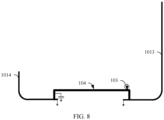
- the antenna further includes a regulation circuit 105, coupled between a predetermined position of the transmission line and ground, and includes at least one of a capacitor and an inductor.
- an antenna in a second aspect of this application, includes a radiator pair, where a first radiator and a second radiator in the radiator pair each include a ground end and an open end; at least one transmission line, coupled to the radiator pair, where the at least one transmission line includes a first transmission line, and the first transmission line includes a first section and a second section of unequal lengths; and a feeding unit, where the feeding unit includes a first feeding part, and the first feeding part is coupled to the first radiator and the second radiator respectively through the first section and the second section.
- the two sections of unequal lengths are coupled to the feeding unit to feed the radiator pair.
- an asymmetrically fed antenna is provided, and therefore excitation currents with a phase difference can be introduced between the radiator pair.
- a multi-mode broadband antenna may be formed, and an antenna pair with high isolation may further be formed.
- the antenna further includes a matching circuit coupled between the first feeding part and the first transmission line.
- the matching circuit includes a capacitor and/or an inductor.
- a length of the first transmission line is less than or equal to 1/10 of a dielectric wavelength corresponding to a lowest operating frequency band of the antenna.
- a difference (T2-T1) between the lengths of the two sections of the first transmission line satisfies 0 mm ⁇ (T2-T1) ⁇ 8 mm, or a ratio T1/T2 of the lengths of the two sections of the first transmission line satisfies 1/2 ⁇ T1/T2 ⁇ 2.
- the at least one transmission line further includes a second transmission line, and the second transmission line includes a third section and a fourth section of unequal lengths.
- the feeding unit includes a second feeding part, and the second feeding part is separately coupled to the radiator pair through the third section and the fourth section. In this manner, the antenna pair with high isolation may be implemented in a simple and effective manner.
- both the first feeding part and the second feeding part are coupled to the ground end of the first radiator or are coupled to the open end of the first radiator, and both the first feeding part and the second feeding part are coupled to the open end of the second radiator or are coupled to the ground end of the second radiator.
- the first feeding part and the second feeding part are respectively coupled to the ground end of the first radiator and the open end of the first radiator, and the first feeding part and the second feeding part are respectively coupled to the open end of the second radiator and the ground end of the second radiator.
- the antenna is configured to generate a first resonance when the first feeding part performs feeding, and the antenna is configured to generate a second resonance when the second feeding part performs feeding.
- the first resonance and the second resonance are at least partially located in a same frequency band, or the first resonance and the second resonance are at least partially located in two different frequency bands. In this manner, frequency bands supported by the antenna pair may be a same frequency band, different frequency bands, or adjacent frequency bands, to obtain an antenna with a wider application scope.
- a ratio T1/T2 of the lengths of the first section and the second section of the first transmission line satisfies 1 ⁇ 4 ⁇ T1/T2 ⁇ 1 ⁇ 2.
- a ratio T3/T4 of the lengths of the third section and the fourth section of the second transmission line satisfies 1 ⁇ 4 ⁇ T3/T4 ⁇ 1 ⁇ 2.
- a difference (T6-T5) between a length T6 of the second transmission line and a length T5 of the first transmission line and a first dielectric wavelength ⁇ 1 of the first resonance or a second dielectric wavelength ⁇ 1 of the second resonance satisfy 1 ⁇ 4 ⁇ 1 ⁇ (T6-T5) ⁇ 3 ⁇ 4 ⁇ 1 or 1 ⁇ 4 ⁇ 2 ⁇ (T6-T5) ⁇ 3 ⁇ 4 ⁇ 2.
- the difference between the lengths may be approximately 1/2 of a dielectric wavelength, to ensure that the excitation currents fed to the radiator pair through the first transmission line and the second transmission line have a phase difference of approximately 180°, thereby implementing a multi-mode broadband antenna and implementing an antenna pair with high isolation.
- the difference (T6-T5) between the lengths of the second transmission line and the first transmission line satisfies 50 mm ⁇ (T6-T5) ⁇ 80 mm.
- the difference (T6-T5) between the lengths of the second transmission line and the first transmission line satisfies 25 mm ⁇ (T6-T5) ⁇ 40 mm.
- the difference between the lengths of the second transmission line and the first transmission line may be about 1/2 of a dielectric wavelength, thereby allowing the phase difference of the excitation currents to be within a range of 1° to 180°.
- an equivalent length of the first transmission line or the second transmission line is determined in at least one of the following manners: a capacitor or an inductor disposed between a corresponding transmission line and a radiator pair, a phase shifter disposed on a corresponding transmission line, and a position at which a corresponding transmission line is coupled to the radiator pair.
- different equivalent lengths may be set for electronic devices of different models, so that an electronic device having an antenna with improved performance can be obtained more pertinently.
- the at least one transmission line may include any one of the following items: a microstrip, a coaxial line, a liquid crystal polymer material, a support antenna body, a glass antenna body, and any combination of the foregoing items.
- the transmission line can be made of a proper material based on different requirements, so that antenna performance can be improved in a cost-effective manner.
- an antenna includes a radiator pair, where a first radiator and a second radiator in the radiator pair each include a ground end and an open end; a first transmission line, coupled to the radiator pair, where the first transmission line includes two sections; and a first feeding part, separately coupled to a first feeding point of the first radiator and a second feeding point of the second radiator through the two sections of the first transmission line, and a phase difference that is of excitation currents provided by the first feeding part and that is between the first feeding point and the second feeding point is within a range of 90° ⁇ 45°.
- the phase difference that is of the excitation currents provided by the first feeding part and that is between the first feeding point and the second feeding point is within a range of 90° ⁇ 30°.
- the antenna may be used in any suitable manner to ensure that the phase difference that is of the excitation currents and that is between the first feeding point and the second feeding point satisfies the foregoing requirement, thereby improving manufacturing flexibility and improving performance of the antenna.
- the antenna further includes a second transmission line and a second feeding part.
- the second transmission line includes two sections.
- the second feeding part is separately coupled to a third feeding point of the first radiator and a fourth feeding point of the second radiator through the two sections of the second transmission line.
- a phase difference that is of a current and that is between the first feeding point and the third feeding point is within a range of 180° ⁇ 60°
- a phase difference that is of a current and that is between the second feeding point and the fourth feeding point is within a range of 180° ⁇ 60°.
- the phase difference that is of the current and that is between the first feeding point and the third feeding point is within a range of 180° ⁇ 45°.
- the phase difference that is of the current and that is between the second feeding point and the fourth feeding point is within a range of 180° ⁇ 45°.
- an electronic device includes a housing, including a side frame; a circuit board, arranged in the housing and including a feeding unit; and an antenna according to the first, the second, or the third aspect.
- the electronic device can implement multi-mode broadband coverage, thereby improving performance of the electronic device.
- a first radiator of the antenna includes a first continuous section of the side frame, and a second radiator includes a second continuous section of the side frame. This arrangement manner is more conducive to improving flexibility of arrangement of the antenna in the electronic device.
- the first radiator and the second radiator are separated on the side frame; or the first radiator and the second radiator are continuous on the side frame.
- the radiator pair is arranged on an inner side of the housing.
- the foregoing several implementations make arrangement of the antenna in the electronic device more flexible, thereby facilitating arrangement of a broadband multi-mode antenna and an antenna pair with high isolation in the electronic device.
- the antenna is arranged on the inner side of the housing. This arrangement manner further improves flexibility of arrangement of the antenna in the electronic device.
- a ground end of the first radiator and a ground end of the second radiator are a common ground end.
- an open end of the first radiator and an open end of the second radiator are disposed opposite to each other and form a slot, and a width of the slot is less than 3 mm.
- the term “including” and similar terms should be understood as non-exclusive inclusion, that is, “including but not limited to”.
- the term “based on” should be understood as “at least partially based on”.
- the term “an embodiment” or “this embodiment” should be understood as “at least one embodiment”.
- the terms “first”, “second”, and the like may refer to different objects or a same object. Other explicit and implied definitions may be further included below.
- connection and “interconnection” may refer to a mechanical connection relationship or a physical connection relationship.
- a connection between A and B or an interconnection between A and B may refer to that a fastened component (such as a screw, a bolt, or a rivet) exists between A and B; or A and B are in contact with each other and are difficult to be separated.
- Coupled may be understood as direct coupling and/or indirect coupling.
- the direct coupling may also be referred to as "electrical connection”, which may be understood as physical contact and electrical conduction of components; or may be understood as a form in which different components in a line structure are connected by using a physical line that can transmit an electrical signal, such as a printed circuit board (printed circuit board, PCB), copper foil, or a conducting wire; and the "indirect coupling” may be understood as electrical conduction of two conductors in an air-space or non-contact manner.
- the indirect coupling may also be referred to as capacitive coupling.
- signal transmission is implemented by forming an equivalent capacitor through coupling a slot between two spaced conductive members.
- the radiator is an apparatus used to receive/transmit electromagnetic wave radiation in an antenna.
- the "antenna" is the radiator in a narrow sense.
- the radiator converts guided wave energy from a transmitter into a radio wave, or converts a radio wave into guided wave energy to radiate and receive the radio wave.
- Modulated high-frequency current energy (or the guided wave energy) generated by the transmitter is transmitted to a transmit radiator through a feeder.
- the radiator converts the modulated high-frequency current energy into specific polarized electromagnetic wave energy and radiates the polarized electromagnetic wave energy in a required direction.
- a receive radiator converts specific polarized electromagnetic wave energy from a specific direction in space into modulated high-frequency current energy, and transmits the modulated high-frequency current energy to an input end of a receiver through a feeder.
- the radiator may be a conductor having a specific shape and size, such as a linear antenna.
- the linear antenna is an antenna composed of one or more metal conductors whose diameter is far less than a wavelength and whose length can be compared with the wavelength.
- the linear antenna can be used as a transmit or receive antenna.
- Main forms of the linear antenna include a dipole antenna, a half-wave dipole antenna, a monopole antenna, a loop antenna, an inverted-F antenna (also called IFA, Inverted-F Antenna), a planar inverted-F antenna (also called PIFA, Planar Inverted-F Antenna), a slot antenna, an antenna array, and the like.
- each dipole antenna usually includes two radiation stubs, and each radiation stub is fed by a feeding part from a feeding end of the radiation stub.
- the inverted-F antenna Inverted-F Antenna, IFA
- IFA Inverted-F Antenna
- the IFA antenna has a feeding point and a ground point. Both the feeding point and the ground point are disposed away from an open end. Because a side view of the IFA antenna is in a shape of an inverted F, the IFA antenna is referred to as the inverted-F antenna.
- a composite right/left-handed (composite right/left-handed, CRLH) antenna may be considered as a combination of a left-hand antenna and a monopole antenna.
- the composite right/left-handed antenna has a feeding point that connects to a capacitor in series and a ground point. The feeding point is disposed away from the ground point. Because the composite right/left-handed antenna has features of both a left-hand transmission line and a right-hand transmission line, the composite right/left-handed antenna is referred to as the composite right/left-handed antenna.
- the slot antenna may include a single radiation stub, and two ends of the radiation stub are grounded to form a slot.
- An "inverted-F radiator/IFA radiator” in this application may be understood as a radiator having one feeding point and one ground point.
- the ground point is located at one end of the radiator, and the other end of the radiator is an open end.
- the feeding point is disposed between the open end and the ground point.
- the feeding point of the IFA radiator is disposed between a center point and the ground point of the radiator.
- that the ground point is located at one end of the IFA radiator may be understood as that the ground point is within 5 mm away from an end part of the end, for example, within 2 mm.
- the open end of the IFA radiator may be understood as that an end part of the end is not grounded within 5 mm.
- the IFA radiator is used to generate a resonance between the ground point and the open end.
- an electrical length of the IFA radiator from the ground point to the open end is about 1/4 of a wavelength corresponding to the resonance.
- a "composite right/left-handed radiator/CRLH radiator” in this application may be understood as a radiator having one feeding point and one ground point.
- the ground point is located at one end of the radiator, and the other end of the radiator is an open end.
- the feeding point is disposed between the open end and the ground point, and a capacitor is connected in series between the feeding point and a feed source.
- a capacitance value of the capacitor connected in series is less than or equal to 1 pF.
- the feeding point of the composite right/left-handed radiator is disposed between a center point and the open end of the radiator.
- that the ground point is located at one end of the composite right/left-handed radiator may be understood as that the ground point is within 5 mm away from an end part of the end, for example, within 2 mm.
- a part of the CRLH radiator from the ground point to the feeding point is used to generate a first resonance.
- an electrical length of the CRLH radiator from the ground point to the feeding point is about 1/8 of a wavelength corresponding to the first resonance.
- the electrical length is between 1/4 wavelength and 1/8 wavelength or is less than 1/8 wavelength.
- a part between the feeding point and the open end of the CRLH radiator is used to generate a second resonance.
- an electrical length of the CRLH radiator from the feeding point to the open end is about 1/4 of a wavelength corresponding to the second resonance.
- the capacitance value of the capacitor connected in series between the feeding point and the feed source may be understood as an equivalent capacitance value. For example, if two capacitors are connected in series, an equivalent capacitance value after the two capacitors are connected in series may be calculated.
- the radiator may alternatively be a slot formed on a conductor.
- an antenna formed by slotting on a surface of the conductor is also referred to as a slot antenna.
- a shape of the slot is a long strip.
- a length of the slot is approximately half a wavelength.
- the slot may be fed through a transmission line that is connected to one side or two sides of the slot, or may be fed through a waveguide or a resonant cavity. In this case, a radio frequency electromagnetic field that radiates electromagnetic waves to space is excited above the slot.
- the feeding unit is a combination of all components of an antenna for receiving and transmitting radio frequency waves.
- the feeding unit may be considered as an antenna part from a first amplifier to a front-end transmitter.
- the feeding unit may be considered as a part after a last power amplifier.
- the "feeding unit” is a radio frequency chip in a narrow sense, or includes a transmission path from a radio frequency chip to a radiator or a feeding point on a transmission line.
- the feeding unit has a function of converting a radio wave into an electrical signal and sending the electrical signal to a receiver component.
- the feeding unit is considered as a part of an antenna, used to convert the radio wave into the electrical signal, and vice versa.
- an antenna When designing an antenna, a possibility and efficiency of maximum power transmission should be considered. Therefore, input impedance of the antenna needs to match a load resistance.
- the feed impedance of the antenna is a combination of resistance, capacitance, and inductance. To ensure a condition of the maximum power transmission, the two impedances (load resistance and feed impedance) should match.
- the matching can be implemented by considering frequency requirements and design parameters (for example, gain, directivity, and radiation efficiency) of the antenna.
- the input impedance includes two resistance elements, namely, a loss resistance and a radiation resistance.
- the loss resistance is a resistance provided by actual components of the antenna
- the feed impedance is a resistance provided by the antenna when the antenna inputs signals. Therefore, the loss resistance and the feed impedance need to operate together to obtain a proper operating antenna feed.
- the radiation resistance is a resistance provided by the antenna to a radiated power. In other words, it indicates a dissipated radiated power.
- the transmission line also referred to as a feed line, is a connection line between a transceiver and a radiator of an antenna.
- the transmission line can directly transmit current waves or electromagnetic waves depending on a frequency and a form.
- a junction that is on a radiator and that is connected to the transmission line is usually referred to as a feeding point.
- the transmission line includes a wire transmission line, a coaxial line transmission line, a waveguide, a microstrip, or the like.
- the transmission line may include a support antenna body, a glass antenna body, or the like based on different implementation forms.
- the transmission line may be implemented by an LCP (Liquid Crystal Polymer, liquid crystal polymer) material, an FPC (Flexible Printed Circuit, flexible printed circuit) board, a PCB (Printed Circuit Board, printed circuit board), or the like based on different carriers.
- LCP Liquid Crystal Polymer, liquid crystal polymer
- FPC Flexible Printed Circuit, flexible printed circuit
- PCB PCB, printed circuit board
- Ground/ground plate may usually refer to at least a part of any ground layer, ground plate, or any ground metal layer in an electronic device, or refer to at least a part of any combination of the foregoing ground layer, ground plate, ground component, or the like.
- the "ground/ground plate” may be used for grounding a component in the electronic device.
- the "ground/ground plate” may be a ground layer of a circuit board of an electronic device, or may be a ground plate formed by using a middle frame of the electronic device or a ground metal layer formed by using a metal thin film below a screen in the electronic device.
- the circuit board may be a printed circuit board (printed circuit board, PCB), for example, an 8-layer, a 10-layer, or 12-layer to 14-layer board having 8, 10, 12, 13, or 14 layers of conductive material, or an element that is separated and electrically insulated by a dielectric layer or insulation layer such as glass fiber, polymer, or the like.
- the circuit board includes a dielectric substrate, a ground layer, and a wiring layer, and the wiring layer and the ground layer are electrically connected through a via.
- components such as a display, a touchscreen, an input button, a transmitter, a processor, a memory, a battery, a charging circuit, and a system on chip (system on chip, SoC) structure may be installed on or connected to a circuit board, or electrically connected to a wiring layer and/or a ground layer in the circuit board.
- a radio frequency source is disposed at the wiring layer.
- ground layer, ground plate, or ground metal layer is made of conductive materials.
- the conductive material may be any one of the following materials: copper, aluminum, stainless steel, brass and alloys thereof, copper foil on insulation laminates, aluminum foil on insulation laminates, gold foil on insulation laminates, silver-plated copper, silver-plated copper foil on insulation laminates, silver foil on insulation laminates and tin-plated copper, cloth impregnated with graphite powder, graphite-coated laminates, copper-plated laminates, brass-plated laminates and aluminum-plated laminates.
- the ground layer/ground plate/ground metal layer may alternatively be made of other conductive materials.
- the resonance frequency is also called a resonant frequency.
- the resonance frequency may be a frequency at which an imaginary part of input impedance of an antenna is zero.
- the resonance frequency may have a frequency range, that is, a frequency range in which resonance occurs.
- a frequency corresponding to a strongest resonance point equals a center frequency minus a point frequency.
- a characteristic of a return loss of the center frequency may be less than -20 dB.
- Resonant frequency band/communication frequency band/operating frequency band Regardless of a type of an antenna, the antenna always operates in a specific frequency range (frequency band width).
- an operating frequency band of an antenna that supports a B40 frequency band includes frequencies in a range of 2300 MHz to 2400 MHz, or in other words, the operating frequency band of the antenna includes the B40 frequency band.
- a frequency range that satisfies specification requirements may be considered as the operating frequency band of the antenna.
- a width of the operating frequency band is called an operating bandwidth.
- An operating bandwidth of an omnidirectional antenna may reach 3% to 5% of the center frequency.
- An operating bandwidth of a directional antenna may reach 5% to 10% of the center frequency.
- a bandwidth may be considered as a frequency range on each of two sides of the center frequency (for example, a resonance frequency of a dipole), where an antenna characteristic is within an acceptable value range of the center frequency.
- Impedance of an antenna usually refers to a ratio of a voltage to a current at an input end of the antenna.
- the impedance of the antenna is a measure of resistance to an electrical signal in the antenna.
- input impedance of an antenna is a complex number, in which a real part is referred to as an input resistance, represented by Ri; and an imaginary part is referred to as input reactance, represented by Xi.
- An antenna whose electrical length is far less than an operating wavelength has high input reactance. For example, a short dipole antenna has high capacitive reactance, and an electrically small loop antenna has high inductive reactance.
- Input impedance of a half-wave dipole with a small diameter is approximately 73.1+j42.5 ohms.
- a length of the oscillator is referred to as a resonance length.
- a length of a resonant half-wave dipole is slightly shorter than a half wavelength in free space, and in engineering, it is estimated that the length is 5% shorter than the half wavelength.
- the input impedance of the antenna is related to factors such as a geometric shape, a size, a position of a feeding point, an operating wavelength, and surrounding environment of the antenna. When a diameter of a linear antenna is large, input impedance changes smoothly with frequency, and an impedance bandwidth of the antenna is wide.
- a main purpose of studying the impedance of the antenna is to realize matching between the antenna and a transmission line.
- input impedance of the antenna should be equal to characteristic impedance of the transmission line.
- input impedance of the antenna should be equal to a conjugate complex number of load impedance.
- the receiver usually has impedance of a real number.
- the system efficiency is a ratio of power radiated by an antenna to space (that is, power that is of a part of electromagnetic waves and that is effectively converted) to input power of the antenna.
- the system efficiency is actual efficiency obtained after antenna port matching is considered, that is, the system efficiency of the antenna is the actual efficiency (that is, efficiency) of the antenna.
- the radiation efficiency is a ratio of power radiated by an antenna (that is, power that is of a part of electromagnetic waves and that is effectively converted) to active power input to the antenna.
- the active power input to the antenna Input power of the antenna-Loss power.
- the loss power mainly includes return loss power and ohmic loss power and/or dielectric loss power of metal.
- the radiation efficiency is a value used to measure a radiation capability of an antenna. Metal loss and dielectric loss are factors that affect the radiation efficiency.
- efficiency is generally represented by a percentage, and there is a corresponding conversion relationship between the efficiency and dB. A closer efficiency to 0 dB indicates better efficiency of an antenna.
- dB means decibel, is a logarithmic concept with a base often. The decibel is only used to evaluate a proportional relationship between a physical quantity and another physical quantity. The decibel has no physical dimension.
- the return loss of an antenna may be understood as a ratio of power of a signal reflected back to an antenna port by an antenna circuit to transmit power of the antenna port.
- a smaller reflected signal indicates a larger signal radiated from the antenna to space, and higher radiation efficiency of the antenna.
- a larger reflected signal indicates a smaller signal radiated from the antenna to space, and lower radiation efficiency of the antenna.
- the return loss of the antenna may be represented by an S11 parameter, and S11 is one of S parameters.
- S 11 indicates a reflection coefficient. This parameter indicates transmit efficiency of the antenna.
- the S11 parameter is usually a negative number.
- a smaller S11 parameter indicates a smaller return loss of the antenna, smaller energy reflected by the antenna, that is, more energy actually enters the antenna, and higher system efficiency of the antenna.
- a larger S11 parameter indicates a larger return loss of the antenna, and lower system efficiency of the antenna.
- an S11 value of -6 dB is generally used as a standard.
- an S11 value of an antenna is less than -6 dB, it may be considered that the antenna can operate normally, or it may be considered that transmit efficiency of the antenna is good.
- the isolation means when an antenna transmits a signal, a ratio of a signal received through another antenna to the signal transmitted by the transmit antenna.
- the isolation is a physical quantity used to measure a degree of mutual coupling between antennas. If two antennas form a dual-port network, isolation between the two antennas is S21 and S12 between the antennas.
- the isolation of the antenna may be represented by parameters S21 and S12.
- the parameters S21 and S12 are usually negative numbers. Smaller parameters S21 and S12 indicate larger isolation between antennas, and a smaller degree of mutual coupling between the antennas. Larger parameters S21 and S12 indicate smaller isolation between antennas, and a larger degree of mutual coupling between the antennas.
- the isolation of the antenna depends on a radiation pattern of the antenna, a space distance of the antenna, a gain of the antenna, and the like.
- the Smith chart is a computational chart of a circle family with normalized input impedance (or admittance) equivalents on a discrete plane of a reflective system.
- the Smith chart is mainly used for impedance matching of transmission lines.
- a circle line represents a real value of reactance, that is, a resistance value.
- a horizontal line in the middle and lines that are scattered upward and downward represent imaginary values of a resistance force, that is, resistance values generated by a capacitor or an inductor at a high frequency.
- An upward line is a positive number, and a downward line is a negative number.
- a point (1+j0) in the middle of the chart represents a resistance value that has matched impedance.
- a value of a reflection coefficient S 11 is 0.
- An edge of the chart indicates that a length of the reflection coefficient S11 is 1, that is, 100% reflection. Numbers on the edge of the chart represent an angle (0 to 180 degrees) and a wavelength (from zero to a half wavelength) of the reflection coefficient S11.
- L is the physical length
- a is the transmission time period of the electrical or electromagnetic signal in the medium
- b is the transmission time period in the free space.
- the electrical length may be a ratio of a physical length (that is, a mechanical length or a geometric length) to a wavelength of a transmitted electromagnetic wave.
- L is the physical length
- ⁇ is the wavelength of the electromagnetic wave.
- a physical length of a radiator may be set to an electrical length of the radiator ⁇ 10%, for example, ⁇ 5%.
- a wavelength in this application may be a wavelength that is in a dielectric and that corresponds to a center frequency of resonance frequencies, or a wavelength that is in a dielectric and that corresponds to a center frequency of an operating frequency band supported by an antenna.
- a center frequency of a B 1 uplink frequency band (resonance frequencies range from 1920 MHz to 1980 MHz) is 1955 MHz.
- a wavelength may be a wavelength calculated by using the frequency 1955 MHz, or a calculated wavelength in a dielectric (referred to as a dielectric wavelength for short).
- the "wavelength/dielectric wavelength” may also refer to a wavelength/dielectric wavelength corresponding to a resonance frequency, or a non-center frequency of an operating frequency band.
- the dielectric wavelength mentioned in embodiments of this application may be simply understood as a wavelength.
- Codirectional/reverse distribution of currents mentioned in this application should be understood as that directions of main currents on conductors on a same side are codirectional/reverse.
- an annular conductor for example, a current path is also annular
- main currents excited on conductors on two sides of the annular conductor are in reverse directions, the main currents still meet a definition of the codirectionally distributed currents in this application.
- Equivalent length Due to factors such as a transmission distance, a disposed capacitance and/or inductance, and radiation impedance, a phase difference is caused when an electromagnetic wave is transmitted on a transmission dielectric. If the caused phase difference is the same as a phase difference caused when a guided wave is transmitted on a transmission line that has a predetermined length, a predetermined dielectric constant, and no radiation capability, an equivalent length of the transmission dielectric is equal to the predetermined length of the transmission line.
- the equivalent length may be affected by a physical length of a corresponding transmission line in the transmission dielectric, a capacitor and/or an inductor disposed in the transmission dielectric, a disposed phase shifter, a position at which the transmission line is coupled to a radiator, and the like.
- the physical length may be shortened when the equivalent length basically remains unchanged.
- a relationship between a physical length L and an equivalent length Le may satisfy (1-1 ⁇ 3)Le ⁇ L ⁇ (1+1 ⁇ 3)Le or (1-1 ⁇ 4)Le ⁇ L ⁇ (1+1 ⁇ 4)Le.
- SAR Specific absorption rate
- SAR means electromagnetic radiation energy absorbed by a unit mass of substance per unit time.
- An SAR value is usually used internationally to measure thermal effect of terminal radiation. Radiation of a mobile phone is used as an example.
- the SAR may mean a ratio of radiation absorbed by a human body (for example, a head). A lower SAR value indicates a smaller amount of radiation absorbed by the human body.
- ECC Envelope Correlation Coefficient
- the ECC indicates a degree of independence of radiation patterns of two antennas. If one antenna is completely horizontally polarized and the other is completely vertically polarized, correlation between the two antennas is basically 0. Similarly, if one antenna radiates energy only to the sky, and the other antenna radiates energy only to the ground, an ECC of these antennas is basically 0. Therefore, the envelope correlation coefficient takes into account a shape of the radiation pattern, polarization, and even a relative phase of a field between the two antennas.
- the ECC generally represents a relationship between two antennas. For a MIMO antenna system, a plurality groups of ECCs may represent independence between antennas. For example, a MIMO antenna with an ECC lower than 0.5 can operate well.
- a "point” or an “end” in a “feeding end”, a “feeding point”, “ground end”, “open end”, and “one end” cannot be understood as a point in a narrow sense, and may alternatively be considered as a section of radiator that is on an antenna radiator and that includes a first endpoint, or may alternatively be considered as a section of radiator at a junction between a transmission line and a radiator.
- the first endpoint is an endpoint on a first end of the antenna radiator.
- the first end of the antenna radiator is a feeding end, and the feeding end may be considered as a section of radiator that is within a range of 1/8 of a first wavelength away from the first endpoint.
- the first wavelength may be a wavelength corresponding to an operating frequency band of an antenna structure, or may be a wavelength corresponding to a center frequency of an operating frequency band, or a wavelength corresponding to a resonance point.
- the first end of the antenna radiator is a feeding end, and the feeding end may alternatively be considered as a section of radiator within 5 mm away from the first endpoint, or a section of radiator within 3 mm away from the first endpoint.
- the first end of the antenna radiator is a ground end, and the ground end may be considered as a section of radiator within 5 mm away from the first endpoint, or a section of radiator within 3 mm away from the first endpoint.
- the first end of the antenna radiator is an open end, and the open end should be understood in two ways.
- an "open end" of the IFA radiator may be considered as a section of radiator within 5 mm away from the first endpoint, or a section of radiator within 3 mm away from the first endpoint.
- an open end of the CRLH radiator may be considered as a section of radiator more than 5 mm away from an endpoint of a ground end of the CRLH radiator, or a section of radiator more than 10 mm away from an endpoint of a ground end of the CRLH radiator.
- the open end of the CRLH radiator is a feeding end, and a monopole radiator is electrically connected to the feeding end in a direction away from the ground end.
- the monopole radiator may alternatively be considered as an open end of the CRLH radiator. It should be understood that the monopole radiator may be considered as a part of the CRLH radiator.
- Coupled to a ground end should be understood as being electrically connected to or indirectly coupled to the foregoing "ground end”, and an electrical connection point or an indirect coupling point should be located on the foregoing "ground end”.
- Coupled to an open end should be understood as being electrically connected to or indirectly coupled to the foregoing "open end", and an electrical connection point or an indirect coupling point should be located on the foregoing "open end”.
- “near”, “adjacent”, or “close to” means that a distance between two points or parts (for example, a feeding point and a ground end or an open end) having the foregoing relationship (that is, “near”, “adjacent”, or “close to”) does not exceed a specific distance value.
- the distance value may be constrained by using 1/16 of a dielectric wavelength, 1/8 of a dielectric wavelength, or another value.
- the two values are merely used as examples.
- “near”, “adjacent”, or “close to” means that a distance between two points or parts (for example, a feeding point and a ground end or an open end) having the foregoing relationship (that is, “near”, “adjacent”, or “close to”) does not exceed 10 mm, for example, does not exceed 5 mm, or does not exceed 3 mm.
- “near”, “adjacent”, or “close to” means that two points or parts (for example, a feeding point and a ground end or an open end) having the foregoing relationship (that is, “near", “adjacent”, or “close to”) at least partially overlap, or a distance between the two points or parts is considered as 0 mm.
- the feeding point or feeding end mentioned in the foregoing content of this application may be any point in a connection region (which may also be referred to as a junction) of the transmission line and the radiator, for example, a center point.
- a distance from a point (such as a feeding point, a connection point, or a ground point) to a slot or from a slot to a point may mean a distance from the point to a midpoint of the slot, or may refer to a distance from the point to two ends of the slot.
- the technical solutions provided in this application are applicable to an electronic device that uses one or more of the following communication technologies: a Bluetooth (Bluetooth, BT) communication technology, a global positioning system (global positioning system, GPS) communication technology, a wireless fidelity (wireless fidelity, Wi-Fi) communication technology, a global system for mobile communication (global system for mobile communication, GSM) communication technology, a wideband code division multiple access (wideband code division multiple access, WCDMA) communication technology, a long term evolution (long term evolution, LTE) communication technology, a 5G communication technology, and other future communication technologies.
- Bluetooth Bluetooth
- GPS global positioning system
- Wi-Fi wireless fidelity
- GSM global system for mobile communication
- WCDMA wideband code division multiple access
- LTE long term evolution
- 5G communication technology 5G communication technology
- An electronic device in embodiments of this application may be a mobile phone, a tablet computer, a notebook computer, a smart home, a smart band, a smartwatch, a smart helmet, smart glasses, or the like.
- the electronic device may be a handheld device that has a wireless communication function, a computing device, another processing device connected to a wireless modem, a vehicle-mounted device, an electronic device in a 5G network, an electronic device in a future evolved public land mobile network (public land mobile network, PLMN), or the like. This is not limited in embodiments of this application.
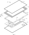
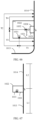
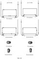
- FIG. 1 shows an example of an electronic device according to this application. An example in which the electronic device is a mobile phone is used for description.
- an electronic device 200 may include a cover (cover) 201, a display/display (display) module 202, a printed circuit board (printed circuit board, PCB) 203, a middle frame (middle frame) 204, and a rear cover (rear cover) 205.
- the cover 201 may be a cover glass (cover glass), or may be replaced with a cover made of another material, for example, a cover made of an ultra-thin glass material or a cover made of a PET (polyethylene terephthalate, polyethylene terephthalate) material.
- the cover 201 may be tightly attached to the display module 202, and may be mainly used to protect the display module 202 and prevent the display module 202 against dust.
- the display module 202 may include a liquid crystal display (liquid crystal display, LCD) panel, a light emitting diode (light emitting diode, LED) display panel, an organic light-emitting diode (organic light-emitting diode, OLED) display panel, or the like. This is not limited in this application.
- the middle frame 204 is mainly used to support the electronic device. As shown in FIG. 1 , the PCB 203 is disposed between the middle frame 204 and the rear cover 205. It should be understood that, in an embodiment, the PCB 203 may alternatively be disposed between the middle frame 204 and the display module 202. This is not limited in this application.
- the printed circuit board PCB 203 may be a flame-resistant material (FR-4) dielectric board, or may be a Rogers (Rogers) dielectric board, or may be a hybrid dielectric board of Rogers and FR-4, or the like.
- FR-4 is a grade designation for a flame-resistant material
- the Rogers dielectric board is a high-frequency board.
- the PCB 203 carries an electronic element, for example, a feeding unit or the like.
- a metal layer may be disposed on the printed circuit board PCB 203.
- the metal layer may be used for grounding the electronic element carried on the printed circuit board PCB 203, or may be used for grounding another element, for example, a support antenna, a side frame antenna, or the like.
- the metal layer may be referred to as a ground plane, a ground plate, or a ground layer.
- the metal layer may be formed by etching metal on a surface of any dielectric board in the PCB 203.
- the metal layer used for grounding may be disposed on a side that is of the printed circuit board PCB 203 and that is close to the middle frame 204.
- an edge of the printed circuit board PCB 203 may be considered as an edge of a ground layer of the printed circuit board PCB 203.
- the metal middle frame 204 may alternatively be used for grounding the foregoing elements.
- the electronic device 200 may further have another ground plane/ground plate/ground layer, as described above. Details are not described herein again.
- the electronic device 200 may further include a battery (not shown in the figure).
- the battery may be disposed between the middle frame 204 and the rear cover 205, or may be disposed between the middle frame 204 and the display module 202. This is not limited in this application.
- the PCB 203 is divided into a mainboard and a sub-board.
- the battery may be disposed between the mainboard and the sub-board.
- the mainboard may be disposed between the middle frame 204 and an upper edge of the battery, and the sub-board may be disposed between the middle frame 204 and a lower edge of the battery.
- the electronic device 200 may further include a side frame 2041, and the side frame 2041 may be at least partially made of a conductive material like metal.
- the side frame 2041 may be disposed between the display module 202 and the rear cover 205, and extend around a periphery of the electronic device 200.
- the side frame 2041 may have four side edges surrounding the display module 202, to help fasten the display module 202.
- the side frame 2041 made of a metal material may be directly used as a metal side frame of the electronic device 200, to form an appearance of the metal side frame. This is applicable to a metal industrial design (industrial design, ID).
- an outer surface of the side frame 2041 may alternatively be made of a non-metal material, for example, a plastic side frame, to form an appearance of a non-metal side frame. This is applicable to a non-metal ID.
- the middle frame 204 may include the side frame 2041, and the middle frame 204 including the side frame 2041 is used as an integrated component, and may support an electronic component in the electronic device.
- the cover 201 and the rear cover 205 are respectively covered along upper and lower edges of the side frame, to form a casing or a housing (housing) of the electronic device.
- the cover 201, the rear cover 205, the side frame 2041, and/or the middle frame 204 may be collectively referred to as a casing or a housing of the electronic device 200.
- casing or housing may mean a part or all of any one of the cover 201, the rear cover 205, the side frame 2041, or the middle frame 204, or mean a part or all of any combination of the cover 201, the rear cover 205, the side frame 2041, or the middle frame 204.
- At least a part of the side frame 2041 on the middle frame 204 may be used as an antenna radiator to receive/transmit a radio frequency signal. There may be a slot between the part of the side frame that is used as the radiator and another part of the middle frame 204, to ensure that the antenna radiator has a good radiation environment.
- the middle frame 204 may be provided with an aperture at the part of the side frame that is used as the radiator, to facilitate radiation of an antenna.
- the side frame 2041 may not be considered as a part of the middle frame 204.
- the side frame 2041 and the middle frame 204 may be connected and integrally formed.
- the side frame 2041 may include a protruding part extending inwards to be connected to the middle frame 204, for example, through a spring, a screw, welding, or the like.
- the protruding part of the side frame 2041 may be further configured to receive a feed signal, so that at least a part of the side frame 2041 is used as a radiator of the antenna to receive/transmit a radio frequency signal.
- a slot between the part of the side frame that is used as the radiator and the middle frame 204, to ensure that the antenna radiator has a good radiation environment, and the antenna has a good signal transmission function.
- embodiments of this application are described mainly by using a side edge that is of the side frame 2041 and that is used as a part of the radiator. It should be understood that other cases are similar, and details are not separately described below.
- the rear cover 205 may be a rear cover made of a metal material, or may be a rear cover made of a non-conductive material, for example, a glass rear cover, a plastic rear cover, or another non-metal rear cover, or may be a rear cover made of both a conductive material and a non-conductive material.
- the antenna of the electronic device 200 may alternatively be disposed on an inner side of the housing, and more specifically, disposed on an inner side of the side frame 2041.
- the antenna radiator may be located in the electronic device 200 and disposed along the side frame 2041.
- the antenna radiator is disposed in a manner of abutting the side frame 2041, so that a volume occupied by the antenna radiator is minimized, and the antenna radiator is closer to the outside of the electronic device 200, thereby achieving better signal transmission effect.
- disposing the antenna radiator in the manner of abutting the side frame 2041 means that the antenna radiator may be disposed immediately against the side frame 2041, or may be disposed close to the side frame 2041. For example, there can be a specific small slot between the antenna radiator and the side frame 2041.
- the antenna of the electronic device 200 may alternatively be disposed at any other proper position in the housing, for example, at a support antenna, a millimeter-wave module, or the like. Clearance of the antenna disposed in the housing may be obtained through a slit/hole on any one of the middle frame 204, the side frame 2041, the rear cover 205, and/or the display 202, or may be obtained through a non-conductive slot/aperture formed between any several thereof. The clearance of the antenna may ensure radiation performance of the antenna. It should be understood that the clearance of the antenna may be a non-conductive region formed by any conductive component in the electronic device 200, and the antenna radiates a signal to external space through the non-conductive region.
- the antenna may be in a form based on a flexible printed circuit (Flexible Printed Circuit, FPC), a form based on laser direct structuring (laser direct structuring, LDS), or a form like a microstrip antenna (Microstrip Disk Antenna, MDA).
- FPC Flexible Printed Circuit
- LDS laser direct structuring
- MDA microstrip antenna
- the antenna may alternatively use a transparent structure embedded in a screen of the electronic device 200, so that the antenna is a transparent antenna element embedded in the screen of the electronic device 200.
- FIG. 1 a structure and an arrangement of the electronic device shown in FIG. 1 are merely examples, and are not intended to limit the protection scope of this application. Another electronic device of any appropriate structure or arrangement is also possible as long as applicable.
- the structure shown in FIG. 1 is used as an example to describe the electronic device 200 according to this embodiment of this application. It should be understood that another electronic device 200 is similar. Details are not separately described below.
- the broadband antenna on the electronic device 200 may use distributed feeding for better hand-held performance.
- two monopole antennas located above a mobile phone are connected through distributed feeding, and signals/guided waves with a phase difference of approximately 90° are introduced to the two antennas, to present effect of dual-resonance broadband matching.
- Distributed feeding may alternatively be implemented on the two monopole antennas located above the mobile phone and a third monopole antenna located at a lower right corner, and phase differences of approximately 60° and approximately 120° are introduced to the three antennas in sequence, to present effect of three-resonance broadband matching. Therefore, bandwidth expansion of a single antenna may be implemented by increasing a quantity of radiators.
- a distributed antenna design may be used, for example, symmetric feeding and anti-symmetrical feeding are used to excite radiators of a symmetric structure, to implement a MIMO antenna pair in an orthogonal mode.
- the radiators are symmetrically designed on two sides of the mobile phone, and a low-frequency dual-mode antenna pair is implemented through symmetric and anti-symmetrical feeding connections with a broadband matching circuit.
- both the two antennas have specific bandwidths and high isolation.
- An embodiment of this application further provides an antenna.
- the antenna feeds a radiator through a transmission line 104 having a predetermined length.
- a feeding unit 103 can also stimulate a transmission line mode on the transmission line 104 to form resonance while exciting a radiator mode to form a resonance.
- the transmission line mode can be superimposed with the radiator mode, so that efficiency and bandwidth of the antenna can be effectively improved.
- the transmission line 104 mentioned in this application may include but is not limited to a microstrip, a strip line, a coaxial line, another linear conductor, or any combination of the foregoing items.
- the linear conductor may be one or a combination of the following: a linear conductive material that forms an LCP, an FPC, and/or a PCB; or a linear conductor (for example, an LDS antenna body or a glass/ceramic antenna body) that is formed on an insulation dielectric.
- the linear conductor may be understood as a strip-shaped or curved conductor whose length is greater than 2-fold of a width.
- the transmission line can be made of various appropriate materials or wires, a degree of freedom of design and structure is high, and the transmission line can be designed at any appropriate position of an electronic device, thereby facilitating design flexibility of the antenna and the electronic device.
- an invention concept according to embodiments of the present disclosure is described mainly by using an example in which a commonly used microstrip is used as the transmission line 104. It should be understood that a case in which the transmission line 104 is formed in another manner is similar, and details are not separately described below.
- the microstrip is a transmission line 104 formed by a single conductor strip supported on a dielectric substrate.
- the microstrip is formed by the dielectric substrate, a conductor strip on the dielectric substrate, and metal ground at the bottom of a dielectric.
- FIG. 2 shows an example cross-sectional view of a 50 ohm microstrip cut in an extension direction perpendicular to the conductor strip.
- a width W of the conductor strip ranges approximately from 1 mm to 1.4 mm, for example, approximately 1.2 mm
- a height h of the dielectric substrate is between 0.6 mm and 0.8 mm, for example, approximately 0.7 mm.
- a dielectric constant ⁇ of the dielectric substrate is approximately 4.4.
- a length T of the transmission line 104 is set to satisfy T ⁇ 1 ⁇ 4 ⁇ or T ⁇ 1 ⁇ 2 ⁇ , where ⁇ is a dielectric wavelength corresponding to one of resonances generated by the antenna when the antenna is fed.
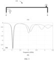
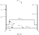
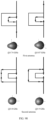
- FIG. 3 shows an example structure of the transmission line 104.
- the transmission line 104 includes two ends, that is, a first end and a second end.
- the two ends of the transmission line 104 may be grounded or open.
- one end or the two ends of the transmission line 104 may be directly grounded, and the end or each of the two ends may be referred to as a ground end.
- the ground end may alternatively be grounded by coupling close to a ground end of the radiator of the antenna.
- the transmission line 104 is directly grounded or grounded through coupling within 5 mm away from an end part of one end, for example, approximately 2 mm away from the end part.
- one end or the two ends of the transmission line 104 may be open by not being grounded, and the end or each of the two ends may be referred to as an open end. In some embodiments, the end may alternatively be open by coupling close to an open end of the radiator of the antenna. In some embodiments, the transmission line 104 is not grounded within 5 mm away from an end part of one end, for example, within 2 mm away from the end part.
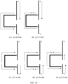
- FIG. 4(A) shows a case in which both the two ends of the transmission line 104 are grounded.
- the transmission line 104 forms a transmission line 104 of a type of a loop radiator, and the length T of the transmission line 104 is approximately 1 ⁇ 2 ⁇ , where ⁇ is a dielectric wavelength corresponding to a lowest resonance of resonances generated by the antenna when the antenna is fed.
- the length T is approximately 1 ⁇ 2 ⁇
- the length T of the transmission line satisfies 1 ⁇ 2 ⁇ 1 ⁇ T ⁇ 1 ⁇ 2 ⁇ 2, where ⁇ 1 and ⁇ 2 are respectively a minimum dielectric wavelength and a maximum dielectric wavelength of an operating frequency band corresponding to a lowest resonance generated by the antenna when the feeding unit performs feeding. It should be understood that the dielectric wavelength mentioned in the present disclosure is a wavelength range.
- the transmission line 104 is used as a conductor structure.
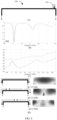
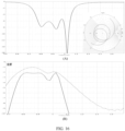
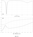
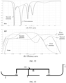
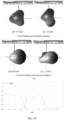
- FIG. 4(B) and FIG. 4(C) respectively show schematic diagrams of S11 parameters and efficiency of the transmission line 104 existing when the transmission line 104 is excited. Because the transmission line 104 is in a closed environment, radiation efficiency of the transmission line 104 is very low, and can be basically negligible.
- FIG. 4(D) shows schematic diagrams of current and electric field distribution of the transmission line 104 existing when the transmission line 104 is excited.
- FIG. 4(D) shows that resonance frequencies of the three transmission line modes may be respectively corresponding to 1.05 GHz, 2.14 GHz, and 3.2 GHz.
- the feeding unit feeds the transmission line, and then feeds a first radiator and a second radiator by coupling the transmission line
- the first radiator is configured to generate a first resonance
- the transmission line is configured to generate a resonance adjacent to the first resonance
- the second radiator is configured to generate a second resonance
- the transmission line is further configured to generate a resonance adjacent to the second resonance.
- an adjacent resonance should be understood as that, both of the two resonances include frequencies of a same operating frequency band; the two resonances respectively include frequencies of adjacent operating frequency bands; or the two resonances are adjacent resonances in an S11 curve diagram of an antenna structure and have an overlapping region in a range below -2 dB.
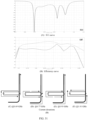
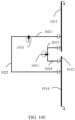
- the regulation circuit may include a capacitor and/or an inductor. Specifically, if a grounded capacitor can be disposed at a current strength point in a half-wavelength mode and an electric field strength point in a 1-fold wavelength mode or a 1.5-fold wavelength mode, a resonance frequency in a medium and high frequency band can be shifted downwards. If an inductor can be disposed at the foregoing position, a resonance frequency in a medium and high frequency band can be shifted upwards.
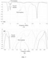
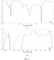
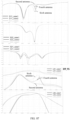
- a capacitor is loaded at a current strength region in a 1/2 wavelength mode (corresponding to 1.05 GHz in FIG. 4(D) ) and an electric field strength region in a 1-fold wavelength mode (corresponding to 2.14 GHz in FIG. 4(D) ) and a 3/2 wavelength mode (corresponding to 3.2 GHz in FIG. 4(D) ), as shown in FIG. 5(A) , a low frequency mode (such as the 1/2 wavelength mode) can be basically unchanged, and a medium frequency mode (such as the 1-fold wavelength mode) and a high frequency mode (such as the 1.5-fold wavelength mode) are shifted downwards, as shown in FIG. 5(B) . In this way, the low frequency mode, the medium frequency mode, and the high frequency mode can be adjusted to be close to a needed design frequency band, thereby further improving performance of the antenna.
- a low frequency mode such as the 1/2 wavelength mode
- a medium frequency mode such as the 1-fold wavelength mode
- a high frequency mode such as the 1.5-fold wavelength mode
- an electrical length of the transmission line 104 corresponds to approximately 1/2 or approximately 1/4 of a dielectric wavelength corresponding to a resonance frequency (for example, a lowest resonance frequency).
- the electrical length of the transmission line 104 corresponds to approximately 1/2 of a dielectric wavelength corresponding to a resonance frequency (for example, the lowest resonance frequency), where the length T of the transmission line satisfies 1 ⁇ 2 ⁇ 1 ⁇ T ⁇ 1 ⁇ 2 ⁇ 2, and ⁇ 1 and ⁇ 2 are respectively a minimum dielectric wavelength and a maximum dielectric wavelength of an operating frequency band corresponding to a lowest resonance generated by the antenna when the feeding unit performs feeding.
- the electrical length of the transmission line 104 corresponds to approximately 1/4 of a dielectric wavelength corresponding to a resonance frequency (for example, the lowest resonance frequency), where the length T of the transmission line satisfies 1 ⁇ 4 ⁇ 1 ⁇ T ⁇ 1 ⁇ 4 ⁇ 2, and ⁇ 1 and ⁇ 2 are respectively a minimum dielectric wavelength and a maximum dielectric wavelength of an operating frequency band corresponding to a lowest resonance generated by the antenna when the feeding unit performs feeding.
- the transmission line 104 may be designed without space dependence, and therefore a structure of the transmission line 104 may be sufficiently miniaturized.
- the electrical length of the transmission line 104 may be shortened in a manner such as increasing a dielectric coefficient of a dielectric.
- a physical length is shortened accordingly.
- a physical length corresponding to 1/2 of a dielectric wavelength corresponding to the lowest resonance frequency is approximately 75 mm.
- a physical length corresponding to 1/2 of a dielectric wavelength corresponding to the lowest resonance frequency is approximately 32 mm.
- a physical length corresponding to 1/2 of a dielectric wavelength corresponding to the lowest resonance frequency is approximately 22 mm.
- the length of the transmission line 104 may be reduced by using a dielectric with a high dielectric constant, thereby reducing an area occupied by the transmission line 104, and facilitating miniaturization of an antenna and an electronic device.
- the transmission line 104 may alternatively use a curved structure to reduce the occupied area, thereby facilitating miniaturization of an antenna and an electronic device.
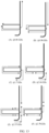
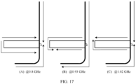
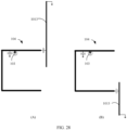
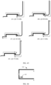
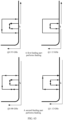
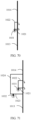
- one end of the transmission line 104 is connected close to a ground end of an IFA radiator, and the other end is directly grounded (as shown in FIG. 6(A) ).
- a length of the radiator is approximately 1/4 of a dielectric wavelength corresponding to a resonance frequency of the antenna.
- the IFA radiator forms a low frequency antenna, and a resonance generated by the IFA radiator may cover a low frequency band.
- one end of the transmission line 104 is connected close to a ground end of an IFA radiator, and the other end is directly grounded (as shown in FIG. 6(B) ).
- a length of the radiator is approximately 1/4 of a dielectric wavelength corresponding to a resonance frequency of the antenna.
- the IFA radiator forms a medium frequency antenna, and a resonance generated by the IFA radiator may cover a medium frequency band. Because the connection points between the transmission line 104 and the radiators are close to the ground points of the radiators, the transmission line 104 in this case is similar to a transmission line 104 that is grounded at two ends.
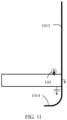
- the radiator uses a metal side frame, and is disposed at a corner at any position of a side frame of the electronic device.
- the transmission line 104 when feeding is performed, the transmission line 104 (whose length is approximately 1/2 of a dielectric wavelength corresponding to a resonance frequency of the antenna) can separately generate three resonances at a low frequency, a medium frequency, and a high frequency, to form transmission line modes.
- the radiator When feeding is performed on the transmission line 104 in the antenna structure shown in each of FIG. 6(A) and FIG. 6(B) , the radiator separately generates resonances at a low frequency, a medium frequency, and a high frequency, to form radiator modes.
- the length of the transmission line 104 is set to approximately 1/2 of a dielectric wavelength corresponding to a low frequency resonance frequency, so that the transmission line mode and the radiator mode are superimposed in corresponding frequency bands, thereby effectively improving efficiency and a bandwidth.
- the transmission line 104 is connected close to the ground end of the radiator, and may satisfy a boundary condition of the transmission line mode.
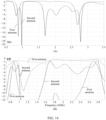
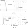
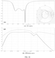
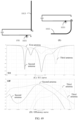
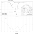
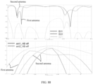
- FIG. 7(A) and FIG. 7(B) respectively show diagrams of S 11 curves and efficiency of the three types of antennas. It may be found that the structure of the transmission line 104 implements mode extension for both a low frequency band and a high frequency band of the second antenna, and also implements mode extension for a low frequency band of the third antenna, thereby greatly improving an efficiency bandwidth.
- FIG. 6(A) and FIG. 6(B) respectively show a case in which one end of the transmission line 104 is connected to one end of the radiator.
- two ends of the transmission line 104 may be respectively connected to radiators operating in a same frequency band or different frequency bands.
- the radiators respectively connected to the two ends of the transmission line 104 may include a continuous section of a side frame. This may include two cases. One case is that the first radiator and the second radiator that are connected to the transmission line are connected to each other and include the continuous section of the side frame. The other case is that the first radiator and the second radiator each include a continuous section of the side frame, but the sections in which the first radiator and the second radiator are located are separated.
- the separation herein may mean that two conductive sections are isolated by using a non-conductive material or mean that two conductive sections are connected by using another part of the side frame, and therefore, ground ends of the two conductive sections are separated; or mean that two conductive sections of the first radiator and the second radiator include both a non-conductive material and another part of the side frame.
- the two ends of the transmission line 104 are respectively connected to the radiators operating in the same frequency band or different frequency bands.
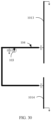
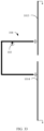
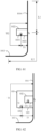
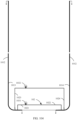
- FIG. 8 shows that one end of the transmission line 104 is connected to a first radiator 1013, and the other end is connected to a second radiator 1014.
- the first radiator 1013 and the second radiator 1014 operate in different frequency bands, for example, operate respectively in a low frequency band and a medium frequency band.
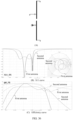
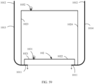
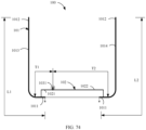
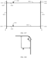
- FIG. 54 an example structure of an antenna 100 is shown below in FIG. 54 .
- the antenna 100 shown in FIG. 54 includes a radiator pair 101 (including the first radiator 1013 and the second radiator 1014) operating in a same frequency band, a transmission line 102, and a feeding unit 1031.
- the transmission line is separately connected close to a ground end of the first radiator 1013 and a ground end of the second radiator 1014. It should be understood that the transmission line may be separately connected close to an open end of the first radiator 1013 and an open end of the second radiator 1014; or one end of the transmission line is connected to the ground end of one of the radiators, and the other end is connected to the open end of the other radiator.
- Transmission lines connected to radiators operating in a same frequency band or different frequency bands each include two sections of unequal equivalent lengths, for example, two sections of unequal physical lengths.
- an inventive concept according to the present disclosure is described mainly by using a physical length of a transmission line as an example. It should be understood that, there may be one or more transmission lines connected to the radiators operating in the same frequency band or different frequency bands, for example, two transmission lines. Two ends of each transmission line are respectively connected to the radiators operating in the same frequency band or different frequency bands, and each transmission line includes two sections of unequal equivalent lengths, for example, two sections of unequal physical lengths.
- the equivalent length may be further determined by using at least one of the following: a capacitor or an inductor disposed between a corresponding transmission line and a radiator pair, a phase shifter disposed on a corresponding transmission line, and a position at which a corresponding transmission line is coupled to the radiator pair.
- the “length” mentioned in this specification usually means the physical length.
- the feeding unit is coupled to the first radiator 1013 and the second radiator 1014 respectively through the two sections, as shown in FIG. 8 or FIG. 54 .
- the equivalent lengths of the two sections are different, and therefore excitation currents provided by the feeding unit have a phase difference when the excitation currents are transmitted to the first radiator 1013 and the second radiator 1014.
- a difference between the lengths of the two sections may be between 1/8 and 3/8 of a dielectric wavelength, for example, approximately 1/4 of a dielectric wavelength.
- a dielectric wavelength corresponding to a center frequency 1955 MHz of the frequency band is 15 cm. Therefore, it is obtained through calculation that in some embodiments, the difference between the lengths of the two sections may be between 1 cm and 7 cm.
- a difference between lengths of two sections of a transmission line may be less than 1/8 or less.
- a difference D between lengths may be between 1 cm and 7 cm indicates that 1 cm ⁇ D ⁇ 7 cm.
- Other ranges of proportions and/or angles are similar.
- the excitation currents respectively reach a feeding point A and a feeding point B (for example, an electrical connection point between the transmission line and the two radiators) through the two sections of the transmission line, and have a phase difference ⁇ .
- the phase difference is within a range of 90° ⁇ 45°.
- the phase difference of the excitation currents obtained when the excitation currents respectively reach the feeding point A and the feeding point B through the two sections is within a range of 90° ⁇ 30°.
- the length of the transmission line is an odd multiple of 1/2 of a dielectric wavelength, for example, 1/2 of a dielectric wavelength.
- a difference between equivalent lengths of the two sections of the transmission line is 1/4 of a dielectric wavelength.
- a feeding part can implement equal-amplitude codirectional currents at the point A and the point B.
- currents excited by the feeding part on the radiator pair 101 are codirectional.
- that the length of the transmission line is an odd multiple of 1/2 of a dielectric wavelength may be understood as that the length of the transmission line is within a range of [the odd multiple of 1/2 of a dielectric wavelength ⁇ (1 ⁇ 20%)].
- that the difference between the lengths of the two sections of the transmission line is 1/4 of a dielectric wavelength may be understood as that the difference between the lengths is within a range of [1/4 of a dielectric wavelength ⁇ (1 ⁇ 10%)].
- a relationship between a physical length L and an equivalent length Le may satisfy (1-1 ⁇ 3)Le ⁇ L ⁇ (1+1 ⁇ 3)Le or (1-1 ⁇ 4)Le ⁇ L ⁇ (1+1 ⁇ 4)Le.
- the length of the transmission line is an even multiple of 1/2 of a dielectric wavelength, for example, 1-fold of a dielectric wavelength.
- the difference between the two sections of the transmission line is 1/4 of a dielectric wavelength.
- the feeding part can implement equal-amplitude reverse currents at the point A and the point B. In an embodiment, currents excited by the feeding part on the radiator pair 101 are reverse.
- that the length of the transmission line is an even multiple of 1/2 of a dielectric wavelength may be understood as that the length of the transmission line is within a range of (the even multiple of 1/2 of a dielectric wavelength ⁇ (1 ⁇ 20%)).
- that the difference between the lengths of the two sections of the transmission line is 1/4 of a dielectric wavelength may be understood as that the difference between the lengths is within a range of (1/4 of a dielectric wavelength ⁇ (1 ⁇ 10%)).
- a relationship between a physical length L and an equivalent length Le may satisfy (1-1 ⁇ 3)Le ⁇ L ⁇ (1+1 ⁇ 3)Le or (1-1 ⁇ 4)Le ⁇ L ⁇ (1+1 ⁇ 4)Le.
- the lengths of the two sections of the transmission line are unequal, for example, based on a phase difference needed on the radiator pair 101, the difference between the lengths of the two sections may be set to another range from between 1/8 and 3/8 of a dielectric wavelength.
- the antenna 100 can also separately control phase differences of currents on the radiator pair 101, thereby helping improve various types of performance of the antenna 100.
- the antenna also includes a radiator pair, at least one transmission line, and a feeding unit.
- the at least one transmission line includes two sections.
- the feeding unit is separately coupled to a first feeding point of a first radiator and a second feeding point of a second radiator through the two sections.
- Equivalent lengths of the two sections are unequal, so that a phase difference that is of excitation currents provided by the feeding unit and that is between the first feeding point and the second feeding point is within a range of 90° ⁇ 45°.
- the phase difference is within a range of 90° ⁇ 30°.
- the equivalent lengths of the two sections may be determined by using at least one of the following: a capacitor or an inductor disposed between a corresponding section and a radiator pair, a phase shifter disposed on a corresponding section, and a position at which a corresponding section is coupled to the radiator pair.
- FIG. 8 shows a schematic diagram in which one end of the transmission line 104 is connected to a first radiator 1013 and is connected close to a ground end of the first radiator 1013, and the other end of the transmission line 104 is connected to a second radiator 1014 and is connected close to a ground end of the second radiator 1014.
- the first radiator 1013 may be a radiator operating in a low frequency band.
- the second radiator 1014 may be a radiator operating in a medium frequency band.
- an electrical length of the first radiator 1013 is approximately between 1/8 and 3/8 of a dielectric wavelength corresponding to a first resonance frequency (for example, a low frequency) of the antenna.
- a physical length of a low frequency radiator may be between 45 mm and 70 mm, for example, 58.5 mm.
- An electrical length of the second radiator 1014 is between 1/8 and 3/8 of a dielectric wavelength corresponding to a second resonance frequency (for example, a medium frequency) of the antenna.
- a physical length of a medium frequency radiator may be between 22 mm and 35 mm, for example, 27.5 mm.
- the transmission line 104 uses a microstrip structure, and an electrical length of the transmission line 104 corresponds to approximately 1/2 of a wavelength of a resonance frequency (for example, a low frequency) of a first transmission line.
- a physical length of a low frequency transmission line is approximately between 65 mm and 75 mm, for example, 70 mm.
- a slot may be disposed between each of the first radiator 1013 and the second radiator 1014 and another part of the side frame, and a width of the slot may be within 3 mm.
- the width may be within 2 mm, for example, approximately 1 mm.
- the slot may be filled with a non-conductive material.
- the antenna in this arrangement can separately excite two modes at a low frequency, a medium frequency, and a high frequency to implement coverage of six resonance frequencies in a full frequency band.
- a reflection coefficient S11 and an efficiency curve are shown in FIG. 9(A) and FIG. 9(B)
- current distribution in each mode is shown in FIG. 10 .
- two resonance frequencies of a low frequency band of the antenna are mainly implemented by a low frequency resonance frequency of the first radiator 1013 and a low frequency resonance frequency (corresponding to a 1/2 dielectric wavelength mode) of the transmission line 104.
- two resonance frequencies of a medium frequency band are mainly implemented by a low frequency resonance frequency of the second radiator 1014 and a medium frequency resonance frequency (corresponding to a 1-fold dielectric wavelength mode) of the transmission line 104.
- two resonance frequencies of a high frequency band are mainly implemented by a high frequency resonance frequency of the first radiator 1013 and a high frequency resonance frequency (corresponding to a 1.5-fold dielectric wavelength mode) of the transmission line 104.
- efficiency and a bandwidth of the antenna structure shown in FIG. 8 are significantly increased.
- the radiators shown in FIG. 8 may alternatively be obtained by combining the two IFA radiators into a T radiator structure.
- an electrical length of the first radiator 1013 is approximately between 1/8 and 3/8 of a dielectric wavelength corresponding to a first resonance frequency (for example, a low frequency) of the antenna.
- a physical length of a low frequency radiator may be between 45 mm and 70 mm, for example, 50 mm.
- An electrical length of the second radiator 1014 is between 1/8 and 3/8 of a dielectric wavelength corresponding to a second resonance frequency (for example, a medium frequency) of the antenna.
- a physical length of a medium frequency radiator may be between 22 mm and 35 mm, for example, 30 mm.
- the transmission line 104 uses a microstrip structure, and an electrical length of the transmission line 104 corresponds to approximately 1/2 of a wavelength of a resonance frequency (for example, a low frequency) of a first transmission line.
- a physical length of a low frequency transmission line is approximately between 65 mm and 75 mm, for example, 70 mm.
- An antenna of this structure may also be extended at a low frequency, a medium frequency, and a high frequency, and a reflection coefficient S11 and an efficiency curve of the antenna are shown in FIG. 12(A) and FIG. 12(B) . Current distribution of the six modes is shown in FIG. 13(A) to FIG. 13(F) respectively.
- FIG. 14(A) and FIG. 14(B) respectively show S11 curves and efficiency curves of the two types of antennas. Only one feeding point is disposed on a T-type radiator of the first antenna, and a specific position of the feeding point is not limited. It can be found from FIG. 14 that the first antenna can excite a maximum of three modes of the radiator. Consequently, the mode excitation is insufficient, and an efficiency bandwidth is insufficient.
- the transmission line 104 that is approximately 1/2 of a dielectric wavelength is coupled to the ground end of the radiator for feeding to form the second antenna, both efficiency and a bandwidth of the second antenna can be significantly improved.
- the structure of the transmission line 104 in this application may alternatively be applied to two radiators operating in a same frequency band. In some embodiments, the structure of the transmission line 104 in this application may alternatively be applied to two radiators of equivalent sizes.
- a structure of the T antenna obtained by combining structures of the two IFA radiators is connected close to the ground end for feeding by using the transmission line 104 mentioned above, as shown in FIG. 15 .
- electrical lengths of the first radiator 1013 and the second radiator 1014 are approximately between 1/8 and 3/8 of a dielectric wavelength corresponding to a first resonance frequency (for example, a low frequency) of the antenna.
- a physical length of a low frequency radiator may be between 45 mm and 70 mm, for example, 52.5 mm.
- the transmission line 104 uses a microstrip structure, and an electrical length of the transmission line 104 corresponds to approximately 1/2 of a wavelength of a resonance frequency (for example, a low frequency) of a first transmission line.
- a physical length of a low frequency transmission line is approximately between 65 mm and 75 mm, for example, 74 mm.
- FIG. 16(A) shows a diagram of an S11 curve and an impedance chart of this antenna.
- FIG. 16(B) shows a diagram of an efficiency curve of this antenna.
- FIG. 17(A) to FIG. 17(C) show current distribution for these three modes.
- FIG. 18 shows designs of transmission lines 104 loaded with different dielectrics in the embodiment shown in FIG. 15 .
- FIG. 18(A) shows a first antenna, where a physical length of a transmission line 104 corresponding to 1/2 of a dielectric wavelength corresponding to a lowest resonance frequency is approximately 75 mm when a dielectric constant is 4.4.
- FIG. 18(B) shows a second antenna, where a physical length of a transmission line 104 corresponding to 1/2 of a dielectric wavelength corresponding to a lowest resonance frequency is approximately 32 mm when a dielectric constant is 16.
- FIG. 18(A) shows a first antenna, where a physical length of a transmission line 104 corresponding to 1/2 of a dielectric wavelength corresponding to a lowest resonance frequency is approximately 75 mm when a dielectric constant is 4.4.
- FIG. 18(B) shows a second antenna, where a physical length of a transmission line 104 corresponding to 1/2 of a dielectric wavelength corresponding to a lowest resonance frequency is approximately 32 mm when a di
- FIG. 18(C) shows a third antenna, where a physical length of a transmission line 104 corresponding to 1/2 of a dielectric wavelength corresponding to a lowest resonance frequency is approximately 22 mm when the dielectric constant is 33.
- FIG. 18(D) shows a diagram of S11 curves and an impedance chart of these antennas.
- FIG. 18(E) shows a diagram of efficiency curves of these antennas. It can be learned that the length of the transmission line 104 decreases by more than 2/3 as the dielectric constant increases, but still satisfies a requirement of an electrical length of 1/2 of a dielectric wavelength. Therefore, the antenna modes and the efficiency bandwidth mentioned above can be maintained.
- the transmission line 104 may be in a form of a plurality of bends and windings.
- FIG. 19(A) shows a transmission line 104 (as a transmission line of a first antenna) with a minimum quantity of curved structures when a corresponding dielectric constant is 33.
- FIG. 19(B) shows a transmission line 104 (as a transmission line of a second antenna) with a plurality of curved structures in the same case.
- FIG. 19(C) and FIG. 19(D) respectively show a diagram of S11 curves and a diagram of efficiency curves of the two antenna structures. It can be learned that the transmission line 104 with the plurality of curved structures has little impact on the antenna modes and the efficiency bandwidth, so that the antenna and the electronic device are further miniaturized while a high bandwidth and efficiency are maintained.
- the embodiment in which the transmission line 104 is miniaturized by using different dielectric constants or a plurality of curved structures is merely an example, and is not intended to limit the protection scope of the present disclosure.
- This manner of miniaturizing the transmission line 104 may be applied to any appropriate embodiment, including but not limited to the embodiment shown in FIG. 6 , the embodiment shown in FIG. 8 , the embodiment shown in FIG. 11 , and various embodiments to be mentioned below. Details are not separately described below.
- the structure of the transmission line 104 may be further combined with an impedance matching circuit at a radiator end, to further increase a quantity of resonance frequencies, thereby increasing a bandwidth.
- a structure of the embodiment shown in FIG. 20(A) is similar to that of FIG. 15 , and a difference lies in that an impedance matching circuit in which a capacitor is connected in series and an inductor is connected in parallel is added to a connection point between a transmission line 104 and a radiator in the embodiment shown in FIG. 20(A).
- FIG. 20(B) and FIG. 20(C) respectively show a diagram of an S11 curve and a diagram of an efficiency curve of the antenna structure.
- FIG. 20(B) and FIG. 20(C) respectively show a diagram of an S11 curve and a diagram of an efficiency curve of the antenna structure.
- five modes may be excited in a target frequency band (for example, a low frequency band), for example, mode 1 to mode 5 shown in FIG. 20(B) , and current distribution thereof are shown in (A) to (E) in FIG. 21 .
- a target frequency band for example, a low frequency band
- FIG. 22(A) By using the antenna shown in FIG. 22(A) as a first antenna, the antenna shown in FIG. 15 as a second antenna, and the antenna shown in FIG. 20 as a third antenna, FIG. 22(B) and FIG. 22(C) respectively show diagrams of S11 curves and efficiency curves of the three types of antennas, and FIG. 23(A) and FIG. 23(B) respectively show diagrams of efficiency of the three types of antennas in a left-hand mode and a right-hand mode. As shown in FIG. 22 and FIG. 23 , in free space, compared with the antenna structure (the first antenna) shown in FIG. 22(A) , a -4 dB efficiency bandwidth of the antenna structure (the second antenna) shown in FIG.
- both left-hand holding efficiency and right-hand holding efficiency of the antenna structure shown in FIG. 20(A) reach more than -8.5 dB in an entire low frequency band (700-1200 MHz).
- the impedance matching circuit is used between the transmission line 104 and the low frequency radiator to increase bandwidths of high and low frequency bands.
- the foregoing embodiment is merely an example, and is not intended to limit the protection scope of the present disclosure.
- the impedance matching circuit may be used between the transmission line 104 and a radiator of any proper frequency band, to increase a bandwidth of a corresponding radiation frequency band. Details are not separately described below.
- both the two ends of the transmission line 104 are grounded (directly grounded or connected to the ground end of the radiator).
- the two ends of the transmission line 104 may alternatively be in an open state, that is, are open ends.
- FIG. 24 shows a case in which both the two ends of the transmission line 104 are open.
- a length T of the transmission line 104 is set to approximately 1 ⁇ 2 ⁇ , where ⁇ is a dielectric wavelength corresponding to a lowest resonance of resonances generated by the antenna when the antenna is fed.
- FIG. 25(A) and FIG. 25(B) respectively show schematic diagrams of S11 parameters and efficiency of the transmission line 104 when the transmission line 104 is excited.
- FIG. 26 shows schematic diagrams of current and electric field distribution of the transmission line 104 when the transmission line 104 is excited.
- a resonance frequency of the transmission line mode can be adjusted.
- the regulation circuit may include a capacitor and/or an inductor. Specifically, if a grounded capacitor can be disposed at a current strength point in a half-wavelength mode and an electric field strength point in a 1-fold wavelength mode or a 1.5-fold wavelength mode, a resonance frequency in a medium and high frequency band can be shifted downwards. If an inductor can be disposed at the foregoing position, a resonance frequency in a medium and high frequency band can be shifted upwards.
- a capacitor (as a second antenna) is loaded at a current strength region in a 1/2 wavelength mode (corresponding to 1 GHz in FIG. 26 ) and an electric field strength region in a 1-fold wavelength mode (corresponding to 2.03 GHz in FIG. 26 ) or a 3/2 wavelength mode (corresponding to 3.02 GHz in FIG. 26 ), as shown in FIG. 27(A) , compared with the case of the transmission line 104 shown in FIG. 24 (as a first antenna), a low frequency mode can be basically unchanged, and a medium frequency mode and a high frequency mode are shifted downwards, as shown in FIG. 27(B) . In this way, the low frequency mode, the medium frequency mode, and the high frequency mode can be adjusted to be close to a needed design frequency band, thereby further improving performance of the antenna.
- one end of the transmission line 104 is connected close to an open end of a first composite right/left-handed radiator, and the other end is in an open state (as shown in FIG. 28(A) ).
- a connection point between the structure of the transmission line 104 and the composite right/left-handed radiator is between a center point and the open end of the radiator.
- a length of the radiator is set to 1/4 of a dielectric wavelength corresponding to a first resonance frequency of the antenna.
- one end of the transmission line 104 is connected close to an open end of a second composite right/left-handed radiator, and the other end is in an open state (as shown in FIG. 28(B) ).
- a length of the radiator is 1/4 of a dielectric wavelength corresponding to a second resonance frequency of the antenna. Because the connection points between the transmission line 104 and the radiators are close to the open ends of the radiators, the transmission line 104 in this case is similar to a transmission line 104 that is open at two ends.
- the first composite right/left-handed radiator may be a low frequency radiator, and an operating frequency band of the first composite right/left-handed radiator is a low frequency band.
- the second composite right/left-handed radiator may be a medium frequency radiator, and an operating frequency band of the second composite right/left-handed radiator is a medium frequency band.
- a radiator 1013 shown in FIG. 28 uses a metal side frame and is designed at any position of a side frame of an electronic device.
- the transmission line 104 (whose length is approximately 1/4 of a dielectric wavelength corresponding to a low frequency resonance frequency of the antenna) can separately generate three resonances at a low frequency, a medium frequency, and a high frequency, to form transmission line modes.
- the radiator separately generates resonances at a low frequency, a medium frequency, and a high frequency, to form radiator modes.
- the length of the transmission line 104 is set to approximately 1/2 of a dielectric wavelength corresponding to a low frequency resonance frequency, so that the transmission line mode and the radiator mode can be superimposed in respective frequency bands, thereby effectively improving efficiency and a bandwidth.
- the transmission line 104 is connected close to the open end of the radiator, and may satisfy a boundary condition of the transmission line mode.
- FIG. 27 By using the structure shown in FIG. 27 as a first antenna, the structure shown in FIG. 28(A) as a second antenna, and the structure shown in FIG. 28(B) as a third antenna, FIG. 29(A) and FIG. 29(B) respectively show diagrams of S11 curves and efficiency of the three types of antennas. It may be found that the structure of the transmission line 104 implements mode extension for both a low frequency band and a high frequency band of the low frequency radiator (the second antenna), and also implements mode extension for a low frequency band of the medium frequency radiator (the third antenna), thereby greatly improving an efficiency bandwidth. In addition, in this manner of bandwidth extension, a size of the radiator does not need to be increased, thereby facilitating miniaturization of an antenna and an electronic device.
- FIG. 28 (A) and FIG. 28 (B) respectively show two cases in which one end of the transmission line 104 is connected to the radiator 1013, and the other end is open.
- two ends of the transmission line 104 may be respectively connected to radiators operating in a same frequency band or different frequency bands.
- FIG. 30 shows a schematic diagram in which one end of the transmission line 104 is connected to a first radiator 1013 and is connected close to an open end of the first radiator 1013 by using a capacitor, and the other end of the transmission line 104 is connected to a second radiator 1014 and is connected close to an open end of the second radiator 1014 by using a capacitor.
- the first radiator 1013 may be a low frequency radiator, and an operating frequency band of the first radiator 1013 is a low frequency band.
- the second radiator 1014 may be a medium frequency radiator, and an operating frequency band of the second radiator 1014 is a medium frequency band.
- an electrical length of the first radiator 1013 is approximately between 1/8 and 3/8 of a dielectric wavelength corresponding to a first resonance frequency (for example, a low frequency resonance frequency) of the antenna.
- a physical length of a low frequency radiator may be between 38 mm and 60 mm, for example, 41 mm.
- An electrical length of the second radiator 1014 is between 1/8 and 3/8 of a dielectric wavelength corresponding to a second resonance frequency (for example, a medium frequency resonance frequency) of the antenna.
- a physical length of a medium frequency radiator may be between 12 mm and 35 mm, for example, 16 mm.
- the transmission line 104 uses a microstrip structure, and an electrical length of the transmission line 104 corresponds to approximately 1/2 of a wavelength of a low frequency resonance frequency.
- a physical length of a low frequency transmission line is approximately between 70 mm and 90 mm, for example, 80 mm.
- a slot between open ends that are of the first radiator 1013 and the second radiator 1014 and that are close to each other, and a width of the slot is within 3 mm.
- the width may be within 2 mm, for example, approximately 1 mm.
- the first radiator 1013 and the second radiator 1014 form a slot antenna structure.
- a slot of the slot antenna structure may be filled with a non-conductive material.
- the antenna in this arrangement can implement coverage of five resonance frequencies in a full frequency band, and a reflection coefficient S11 and an efficiency curve are shown in FIG. 31(A) and FIG. 31(B) .
- FIG. 32(A) to FIG. 32(E) show diagrams of current distribution of five modes. As shown in FIG.
- the two resonance frequencies in a low frequency band of the antenna are mainly implemented by a low frequency resonance frequency of the first radiator 1013 and a low frequency resonance frequency (corresponding to 1/2 of a dielectric wavelength) of the transmission line 104
- the three resonance frequencies in a medium and high frequency band are mainly implemented by medium and high frequency resonance frequencies (corresponding to 1-fold and 1.5-fold of a dielectric wavelength) of the second radiator 1014 and the transmission line 104.
- efficiency and a bandwidth of the antenna structure shown in FIG. 30 are multiplied.
- this structure of the transmission line 104 may alternatively be applied to two radiators having a same operating frequency band. In some embodiments, this structure of the transmission line 104 may alternatively be applied to two radiators of equivalent size. As shown in FIG. 33 , structures of two CRLH radiators form a slot antenna structure. The transmission line 104 mentioned above is used to connect close to open ends of the two CRLH radiators for feeding, as shown in FIG. 33 . In an embodiment, the two CRLH radiators may both operate in a low frequency band. In the example shown in FIG. 33 , electrical lengths of the first radiator 1013 and the second radiator 1014 are approximately between 1/8 and 3/8 of a dielectric wavelength corresponding to a low frequency resonance frequency of the antenna.
- physical lengths of the first radiator 1013 and the second radiator 1014 may be between 38 mm and 60 mm, for example, 41 mm.
- the transmission line 104 uses a microstrip structure, and an electrical length of the transmission line 104 corresponds to approximately 1/2 of a wavelength of a low frequency resonance frequency, and a physical length of the transmission line 104 is approximately between 70 mm and 90 mm, for example, 80 mm.
- FIG. 34(A) shows a diagram of an S11 curve and an impedance chart of this antenna.
- FIG. 34(B) shows a diagram of an efficiency curve of this antenna.
- FIG. 35(A) and FIG. 35(B) respectively show current distribution and electric field distribution of the three modes.
- FIG. 36(A) shows a diagram of S11 curves and an impedance chart of the two types of antennas
- FIG. 36(C) shows a diagram of efficiency curves of the two types of antennas
- FIG. 37(A) and FIG. 37(B) respectively show diagrams of efficiency of the two types of antennas in a left-hand mode and a right-hand mode.
- the second antenna can excite one more resonance, thereby significantly improving efficiency and a bandwidth of an antenna.
- efficiency and a bandwidth of the second antenna are improved more significantly.
- the antenna according to embodiments of the present disclosure can improve performance of a hand mode and a head-hand mode.
- both the two ends of the transmission line 104 are grounded (directly grounded or connected to the ground end of the radiator) or both the two ends are open.
- one of the two ends of the transmission line 104 may be grounded, and the other end is open.
- FIG. 38 shows a case in which one of two ends of the transmission line 104 is grounded and the other end is open.
- a length T of the transmission line 104 is set to approximately 1 ⁇ 4 ⁇ , where ⁇ is a dielectric wavelength corresponding to a lowest resonance of resonances generated by the antenna when the antenna is fed.
- FIG. 39(A) and FIG. 39(B) respectively show schematic diagrams of S11 parameters and efficiency of the transmission line 104 when the transmission line 104 is excited. Similar to the foregoing embodiment, because the transmission line 104 is in a closed environment, radiation efficiency of the transmission line 104 is very low, and can be basically negligible.
- FIG. 40 shows schematic diagrams of current and electric field distribution of the transmission line 104 when the transmission line 104 is excited.
- one end of the transmission line 104 is connected close to a ground end of a first IFA radiator, and the other end is in an open state (as shown in FIG. 41(A) ).
- a length of the first IFA radiator is approximately 1 ⁇ 4 of a dielectric wavelength corresponding to a first resonance frequency of the antenna.
- the first IFA radiator operates in a low frequency band.
- one end of the transmission line 104 is connected close to an open end of a second CRLH radiator, and the other end is directly grounded (as shown in FIG. 41(B) ).
- a length of the second CRLH radiator is approximately 1 ⁇ 4 of a dielectric wavelength corresponding to a second resonance frequency of the antenna.
- the second CRLH radiator operates in a medium frequency band.
- FIG. 43 shows a schematic diagram in which one end of the transmission line 104 is connected to a first radiator 1013 and is connected close to a ground end of the first radiator 1013, and the other end of the transmission line 104 is connected to a second radiator 1014 and is connected close to an open end of the second radiator 1014 by using a capacitor.
- the first radiator 1013 may be an IFA radiator
- the second radiator 1014 may be a CRLH radiator.
- an electrical length of the first radiator 1013 is approximately between 1/8 and 3/8 of a dielectric wavelength corresponding to a first resonance frequency of an antenna.
- the first resonance frequency is a frequency in a low frequency band
- a physical length of the first radiator 1013 may be between 50 mm and 75 mm, for example, 63 mm.
- An electrical length of the second radiator 1014 is between 1/8 and 3/8 of a dielectric wavelength corresponding to a second resonance frequency of an antenna.
- the second resonance frequency is a frequency in a medium frequency band
- a physical length of the second radiator 1014 may be between 12 mm and 35 mm, for example, 14.56 mm.
- the transmission line 104 uses a microstrip structure, and an electrical length of the transmission line 104 corresponds to approximately 1/4 of a wavelength of a third resonance frequency.
- the third resonance frequency is a frequency in a low frequency band, and a physical length of the transmission line is approximately between 30 mm and 50 mm, for example, 38 mm.
- the width may be within 2 mm, for example, approximately 1 mm.
- the slot may be filled with a non-conductive material.
- the two ends that are of the first radiator 1013 and the second radiator 1014 and that are close to each other may be a ground end of the first radiator 1013 and a ground end or an open end of the second radiator 1014, or may be an open end of the first radiator 1013 and a ground end or an open end of the second radiator 1014.
- the antenna shown in FIG. 43 can implement coverage of five resonance frequencies in a full frequency band.
- a reflection coefficient S11 and an efficiency curve are shown in FIG. 44(A) and FIG. 44(B) , and a diagram of current direction of each mode is shown in FIG. 45(A) to FIG. 45(E) .
- FIG. 45(A) to FIG. 45(E) As shown in FIG.
- the two resonance frequencies in a low frequency band of the antenna are mainly implemented by a low frequency resonance frequency of the first radiator 1013 and a low frequency resonance frequency (corresponding to 1/4 of a dielectric wavelength) of the transmission line 104
- the three resonance frequencies in a medium and high frequency band are mainly implemented by high frequency resonance frequencies of the second radiator 1014 and the first radiator 1013, and a high frequency resonance frequency (corresponding to 3/4 of a dielectric wavelength) of the transmission line 104.
- efficiency and a bandwidth of the antenna structure shown in FIG. 43 are multiplied.
- the transmission line 104 may use a structure in which a slot is disposed in the middle. That is, the transmission line 104 includes two separate sections, and a capacitor is disposed between the two separate sections, as shown in FIG. 46 .
- a microstrip is designed on upper and lower surfaces of a PCB, and design parameters of the microstrip are similar to the design parameters of the microstrip mentioned above. Similar to a feeding manner of a slot antenna, feeding is performed near the slot, and two modes of the transmission line 104 may be excited.
- a capacitor is connected in series for feeding near the slot, and operating frequency bands of the two modes that are of the transmission line 104 and that are excited are low frequency bands.
- a reflection coefficient S11, efficiency, and current and electric field distribution of the embodiment shown in FIG. 46 are respectively shown in FIG. 47(A) to FIG. 47(D) . Because the transmission line 104 is in a closed environment, radiation efficiency of the transmission line 104 is very low.
- FIG. 48(A) shows changes in S11 curves of the two types of antennas. It can be learned that, similar to a design of the slot antenna, a capacitor is connected in series at an open end of the transmission line 104, and a feed point is moved to a position close to a ground point (for example, a current strength region) for direct feeding, so that the two resonance frequencies excited can be reduced.
- a ground point for example, a current strength region
- one end of the transmission line 104 is connected close to a ground end of a low frequency IFA radiator, and the other end is directly grounded (as shown in FIG. 49(A) ).
- a length of the radiator is 1/4 of a dielectric wavelength corresponding to a resonance frequency of the antenna.
- one end of the transmission line 104 is connected close to a ground end of a low frequency IFA radiator, and the other end is directly grounded (as shown in FIG. 49(B) ).
- a length of the radiator is 1/4 of a dielectric wavelength corresponding to a resonance frequency of the antenna.
- FIG. 49(A) shows diagrams of S11 curves and efficiency of the three types of antennas. It can be found that an efficiency bandwidth of the radiator is greatly improved by using the structure of the transmission line 104 shown in FIG. 48(A) .
- FIG. 50 shows a schematic diagram in which two ends of the transmission line 104 are respectively connected to two low frequency radiators (referred to as a first radiator 1013 and a second radiator 1014 below), and are connected close to ground ends of the first radiator 1013 and the second radiator 1014, where the two radiators form a T antenna structure.
- electrical lengths of the first radiator 1013 and the second radiator 1014 are approximately between 1/8 and 3/8 of a dielectric wavelength corresponding to a low frequency resonance frequency of an antenna.
- physical lengths of the first radiator 1013 and the second radiator 1014 may be between 45 mm and 70 mm, for example, 54 mm.
- the transmission line 104 uses a microstrip structure, and a total electrical length of two sections of the transmission line 104 corresponds to approximately 1/2 of a wavelength of a low frequency resonance frequency, and a physical length of the two sections is approximately between 65 mm and 85 mm, for example, 75 mm.
- a slot may be disposed between each of the first radiator 1013 and the second radiator 1014 and another part of the side frame, and a width of the slot may be within 3 mm. For example, in some embodiments, the width may be within 2 mm, for example, approximately 1 mm.
- the slot may be filled with a non-conductive material.
- the antenna in this arrangement can excite four modes in a low frequency band, to improve a bandwidth of the low frequency band.
- a reflection coefficient S11 and an efficiency curve of the antenna are respectively shown in FIG. 51(A) and FIG. 51(B) , and a diagram of current direction of each mode is shown in FIG. 51(C) to FIG. 51(F) .
- four resonance frequencies in a low frequency band of the antenna are mainly implemented by two modes of the radiators and two modes of the transmission line 104. Compared with a single radiator, an efficiency bandwidth is significantly increased.
- the transmission line 104 may alternatively be in another form.
- the transmission line 104 may be changed from a microstrip form to a support wiring.
- FIG. 52(A) and FIG. 52(B) show S11 curves and efficiency curves of the two types of antennas. It can be learned from FIG. 52(A) and FIG. 52(B) that when the transmission line 104 is the support wiring, a height of the transmission line 104 increases, and radiation efficiency is improved. After the transmission line 104 is connected to a radiator, radiation efficiency of an antenna can be further improved.
- the transmission line and the radiator mentioned in the foregoing embodiments may be made of any proper conductive material.
- the transmission line and the radiator may alternatively be integrated.
- the transmission line and the radiator may be designed by using a laser-direct-structuring (laser-direct-structuring, LDS) technology and directly disposed on a side frame or a support of an electronic device, thereby further improving integration.
- LDS laser-direct-structuring
- the foregoing mainly describes a case in which the transmission line is coupled to two radiators to improve antenna performance. It should be understood that this is merely an example, and is not intended to limit the protection scope of the present disclosure.
- the transmission line may be further coupled to more radiators, to further improve a bandwidth and efficiency of the antenna.
- FIG. 53 shows an embodiment in which the transmission line is coupled to three radiators to extend a bandwidth and efficiency of the antenna.
- the transmission line is disposed, so that a transmission line mode and a radiator mode can be superimposed, thereby improving efficiency and a bandwidth of the antenna.
- the foregoing embodiments may be considered as embodiments of a single antenna.
- a single feeding point disposed in a structure of a transmission line feeds two or more radiators that are spaced or electrically connected, to implement a distributed feeding antenna structure.
- the distributed feed antenna structure has characteristics of multi-mode and a wide band.
- a coupling point (or a feeding point) at which a feeding unit of an antenna structure is coupled to a transmission line deviates from a midpoint of the transmission line, that is, an asymmetric feeding design is used.
- the first end of the transmission line is coupled to the ground end of the first radiator, and the second end is grounded or coupled to the ground end of the second radiator.
- the coupling point (or the feeding point) at which the feeding unit is coupled to the transmission line is located close to the first end or the second end.
- the first end of the transmission line is coupled to the open end of the first radiator, and the second end is open or coupled to the open end of the second radiator.
- the coupling point (or the feeding point) at which the feeding unit is coupled to the transmission line is located close to the midpoint of the transmission line.
- the first end of the transmission line is coupled to the ground end of the first radiator, and the second end is open or coupled to the open end of the second radiator.
- the coupling point (or the feeding point) at which the feeding unit is coupled to the transmission line is located close to the first end.
- that the coupling point (or the feeding point) between the feeding unit and the transmission line is "located close to a midpoint of the first end/second end/transmission line" should be understood as a distance within 5 mm or a distance within 3 mm away from the coupling point to the midpoint of the first end/second end/transmission line.
- an embodiment of this application further provides an antenna.
- the antenna is based on an asymmetric feeding design, to implement a multi-mode broadband antenna, and can implement an antenna pair with high isolation. It should be understood that any one of the foregoing embodiments of a single antenna may be applied to one antenna structure in an antenna pair, and a single antenna split from any one of the following embodiments of an antenna pair may also be considered as an embodiment of a single antenna.
- FIG. 54 shows an example structure of the antenna 100.
- the antenna 100 includes a radiator pair 101, at least one transmission line, and a feeding unit.
- the radiator pair 101 includes two radiators, that is, a first radiator 1013 and a second radiator 1014.
- Each radiator includes a ground end 1011 and an open end 1012.
- Each radiator in the radiator pair 101 is grounded at the ground end 1011, and the radiator is not electrically connected to another radiator at the open end 1012.
- each radiator in the radiator pair 101 may include a continuous section of the side frame.
- This may include two cases. One case is that the first radiator 1013 and the second radiator 1014 in the radiator pair 101 are connected to each other and include a continuous section of the side frame. The other case is that the first radiator 1013 and the second radiator 1014 in the radiator pair 101 each include a continuous section of the side frame, but the sections in which the first radiator 1013 and the second radiator 1014 are located are separated.
- the separation herein may mean that two conductive sections are isolated by using a non-conductive material or mean that two conductive sections are connected by using another part of the side frame, and therefore, ground ends 1011 of the two conductive sections are separated; or mean that two conductive sections of the first radiator 1013 and the second radiator 1014 include both a non-conductive material and another part of the side frame.
- each transmission line includes two sections of unequal equivalent lengths, for example, two sections of unequal physical lengths.
- an inventive concept according to the present disclosure is described mainly by using a physical length of each transmission line as an example.
- the equivalent length may be further determined by using at least one of the following: a capacitor or an inductor disposed between a corresponding transmission line and a radiator pair, a phase shifter disposed on a corresponding transmission line, and a position at which a corresponding transmission line is coupled to the radiator pair. This will be further described below.
- the "length" mentioned in this specification usually means the physical length.
- the feeding unit is coupled to the first radiator 1013 and the second radiator 1014 respectively through the two sections, as shown in FIG. 54 .
- the two sections will be respectively referred to as a first section 1021 and a second section 1022.
- Lengths of the first section 1021 and the second section 1022 are different, and therefore excitation currents provided by the feeding unit have a phase difference when the excitation currents are transmitted to the first radiator 1013 and the second radiator 1014.
- a difference between the lengths of the two sections may be between 1/8 and 3/8 of a dielectric wavelength, for example, approximately 1/4 of a dielectric wavelength.
- the difference between the lengths of the two sections may be between 1 cm and 7 cm.
- a difference between lengths of two sections of a transmission line may be less than 1/8 or less.
- the excitation currents respectively reach a feeding point A and a feeding point B through the first section 1021 and the second section 1022 and have a phase difference ⁇ .
- the phase difference is within a range of 90° ⁇ 45°.
- the phase difference of the excitation currents obtained when the excitation currents respectively reach the feeding point A and the feeding point B through the first section 1021 and the second section 1022 is within a range of 90° ⁇ 30°.
- FIG. 55 shows that a feeding part is separately coupled to the radiator pair 101 through a first section 1021 and a second section 1022 of a transmission line.
- a length of the transmission line is an odd multiple of 1/2 of a dielectric wavelength, for example, 1/2 of a dielectric wavelength.
- a difference between equivalent lengths of the first section 1021 and the second section 1022 is 1/4 of a dielectric wavelength.
- the feeding part can implement equal-amplitude codirectional currents at the point A and the point B.
- currents excited by the feeding part on the radiator pair 101 are codirectional.
- that the length of the transmission line is an odd multiple of 1/2 of a dielectric wavelength may be understood as that the length of the transmission line is within a range of [the odd multiple of 1/2 of a dielectric wavelength ⁇ (1 ⁇ 20%)].
- that the difference between the lengths of the first section 1021 and the second section 1022 is 1/4 of a dielectric wavelength may be understood as that the difference between the lengths of the first section 1021 and the second section 1022 is within a range of [1/4 of a dielectric wavelength ⁇ (1 ⁇ 10%)].
- a relationship between a physical length L and an equivalent length Le may satisfy (1-1 ⁇ 3)Le ⁇ L ⁇ (1+1 ⁇ 3)Le or (1-1 ⁇ 4)Le ⁇ L ⁇ (1+1 ⁇ 4)Le.
- FIG. 56 shows that a feeding part of the feeding unit is separately coupled, through a first section 1021 and a second section 1022 of a longer transmission line, to the radiator pair 101 through a feeding point C and a feeding point D.
- excitation currents respectively reach the feeding point C and the feeding point D through the first section 1021 and the second section 1022, and have a phase difference ⁇ .
- the phase difference is within a range of 90° ⁇ 45°.
- the phase difference of the excitation currents obtained when the excitation currents respectively reach the feeding point C and the point D through the first section 1021 and the second section 1022 is within a range of 90° ⁇ 30°.
- a length of the transmission line is an even multiple of 1/2 of a dielectric wavelength, for example, 1-fold of a dielectric wavelength.
- a difference between lengths of the first section 1021 and the second section 1022 is 1/4 of a dielectric wavelength.
- the feeding part can implement equal-amplitude reverse current strength at the point C and the point D. In an embodiment, currents excited by the feeding part on the radiator pair 101 are reverse.
- that the length of the transmission line is an even multiple of 1/2 of a dielectric wavelength may be understood as that the length of the transmission line is within a range of (the even multiple of 1/2 of a dielectric wavelength ⁇ (1 ⁇ 20%)).
- that the difference between the lengths of the first section 1021 and the second section 1022 is 1/4 of a dielectric wavelength may be understood as that the difference between the lengths of the first section 1021 and the second section 1022 is within a range of (1/4 of a dielectric wavelength ⁇ (1 ⁇ 10%)).
- a relationship between a physical length L and an equivalent length Le may satisfy (1-1 ⁇ 3)Le ⁇ L ⁇ (1+1 ⁇ 3)Le or (1-1 ⁇ 4)Le ⁇ L ⁇ (1+1 ⁇ 4)Le.
- FIG. 55 and FIG. 56 respectively show a case in which the feeding unit includes one feeding part and asymmetrically feeds the radiator pair 101 through one transmission line.
- the lengths of the first section 1021 and the second section 1022 are unequal, for example, based on a phase difference needed on the radiator pair 101, the difference between the lengths of the first section 1021 and the second section 1022 may be set to another range from between 1/8 and 3/8 of a dielectric wavelength.
- the antenna 100 can also separately control phase differences of currents on the radiator pair 101, thereby helping improve various types of performance of the antenna 100.
- the antenna also includes a radiator pair, at least one transmission line, and a feeding unit.
- the at least one transmission line includes two sections.
- the feeding unit is separately coupled to a first feeding point of a first radiator and a second feeding point of a second radiator through the two sections. Equivalent lengths of the two sections are not equal, so that a phase difference that is of excitation currents provided by the feeding unit and that is between the first feeding point and the second feeding point is within a range of 90° ⁇ 45°. For example, in some embodiments, the phase difference is within a range of 90° ⁇ 30°.
- the equivalent lengths of the two sections may be determined by using at least one of the following: a capacitor or an inductor disposed between a corresponding section and a radiator pair, a phase shifter disposed on a corresponding section, and a position at which a corresponding section is coupled to the radiator pair.
- the at least one transmission line when the at least one transmission line includes a first transmission line and a second transmission line, two sections of each transmission line can ensure that a phase difference that is of excitation currents provided by the feeding unit and that is between feeding points is within a range of 90° ⁇ 45°.
- a first feeding part performs feeding at a first feeding point and a second feeding point through the first transmission line
- a second feeding part performs feeding at a third feeding point and a fourth feeding point through the second transmission line.
- a phase difference that is of a current and that is between the first feeding point and the adjacent third feeding point may be within a range of 180° ⁇ 60°, for example, 180° ⁇ 45°.
- a phase difference that is of a current and that is between the second feeding point and the adjacent fourth feeding point may be within a range of 180° ⁇ 60°, for example, 180° ⁇ 45°.
- This may be implemented by making equivalent lengths of the first transmission line and the second transmission line unequal.
- the equivalent length of the transmission line may be determined by using at least one of the following: a capacitor or an inductor disposed between a corresponding transmission line and a radiator pair, a phase shifter disposed on a corresponding transmission line, and a position at which a corresponding transmission line is coupled to the radiator pair. This will be further discussed below.
- the phase difference is introduced to the excitation currents at the feeding points to improve antenna performance.
- antenna performance may be improved by using a similar principle in some antenna structures in a manner of a matching circuit.
- the antenna may further include a matching circuit in addition to a radiator pair, a transmission line, and a feeding unit.
- a difference from the embodiment in FIG. 54 is that a first feeding part of the feeding unit is coupled to a roughly middle position of the transmission line.
- the transmission line includes two sections with a basically same length.
- a total length of the transmission line may be less than or equal to 1/10 of a wavelength corresponding to a frequency band in which the antenna operates.
- a difference (T2-T1) between the lengths of the two sections of the first transmission line satisfies 0 mm ⁇ (T2-T1) ⁇ 8 mm, or a ratio T1/T2 of the lengths of the two sections of the first transmission line satisfies 1/2 ⁇ T1/T2 ⁇ 2.
- the transmission line has a shorter length, and the lengths of the two sections of the transmission line may be equal or have a specific deviation.
- a radiator pair includes a part of a side frame of an electronic device
- such transmission line may be conformal to a radiator.
- Conformal indicates that the transmission line may be a part integrally formed with a conductor forming the radiator pair.
- a middle frame of the electronic device includes a side frame and a mechanical part extending from the side frame to the inside.
- the mechanical part may be integrally formed on the side frame, or integrally formed on another part of the middle frame, to extend to the inside of the electronic device.
- the transmission line may be implemented by a protruding part.
- the transmission line may alternatively be coupled to the radiator pair in any other suitable form, for example, implemented by a conductive member on a support.
- the matching circuit is coupled between the feeding unit and the transmission line, and includes at least one capacitor and one inductor.
- the capacitor and the inductor in the matching circuit form an LC resonant circuit.
- FIG. 57 shows that the matching circuit may include a capacitor connected in series and an inductor connected in parallel between the feeding unit and the transmission line. In this manner, when no excitation current with a phase difference is introduced to the radiator pair, codirectional and/or reverse induced currents on the radiator pair may be implemented, to implement a plurality of operating modes of the antenna.
- FIG. 57 shows a case in which the antenna including the matching circuit uses a T antenna structure, and two ground ends of the radiator pair of the antenna are shared.
- the ground ends of the T antenna structure of the antenna that uses the matching circuit may alternatively be separated by a specific distance. That is, a conductor is disposed between the two ground ends of the radiator pair. In some embodiments, the conductor disposed between the ground ends may be a part of the side frame of the electronic device or any other proper conductor.
- the antenna including the matching circuit may alternatively use a slot antenna structure, as shown in FIG. 58 .
- the antenna including the matching circuit may further include a second transmission line and a second feeding part.
- the second transmission line may include two sections, and the second feeding part is coupled to the first radiator and the second radiator respectively through the two sections. This will be further described below.
- the feeding unit in embodiments of this application may include more than one feeding part, as shown in FIG. 59.
- FIG. 59 shows a case in which two manners in FIG. 55 and FIG. 56 are combined.
- the feeding unit may include two feeding parts, that is, a first feeding part 1031 and a second feeding part 1032.
- at least one transmission line includes two transmission lines, that is, a first transmission line and a second transmission line.
- the first feeding part 1031 is separately coupled to a first radiator 1013 and a second radiator 1014 through a first section 1021 and a second section 1022 of the first transmission line.
- the second feeding part 1032 is coupled to the first radiator 1013 and the second radiator 1014 respectively through a third section 1023 and a fourth section 1024 of the second transmission line.
- the two transmission lines have different equivalent lengths.
- the equivalent length of the first transmission line may be an odd multiple of 1/2 of a first dielectric wavelength of a first frequency band in which the antenna 100 can generate a resonance
- the equivalent length of the second transmission line may be an even multiple of 1/2 of a second dielectric wavelength of a second frequency band in which the antenna 100 can generate a resonance.
- the antenna 100 forms an antenna pair including a first antenna fed by the first feeding part 1031 and a second antenna fed by the second feeding part 1032.
- the first frequency band and the second frequency band may be frequency bands that at least partially overlap.
- the first frequency band and the second frequency band may be a same frequency band, that is, the first frequency band and the second frequency band completely overlap.
- the first frequency band and the second frequency band may partially overlap.
- the first frequency band and the second frequency band are adjacent frequency bands, to implement wider coverage of a radiation frequency band.
- the first frequency band and the second frequency band may alternatively be two frequency bands that not overlap but are close to each other.
- the equivalent length of the first transmission line may be an odd multiple of 1/2 of a dielectric wavelength
- the equivalent length of the second transmission line may be an even multiple of 1/2 of a dielectric wavelength.
- a difference between the equivalent lengths of the two transmission lines is N-fold of 1/2 of a dielectric wavelength, where N is an integer greater than 0.
- the difference between the equivalent lengths of the two transmission lines is between 1/4 and 3/4 of a dielectric wavelength, or between (1/4 to 3/4)*N-fold of a dielectric wavelength, so that high isolation of the antenna pair can be implemented, and performance of the antenna 100 is improved.
- a length of the first transmission line may be an odd multiple of 1/2 of a first dielectric wavelength corresponding to a first resonance generated by the antenna.
- an actual length of the first transmission line may be within a range of ⁇ 20% of an odd multiple of 1/2 of the first dielectric wavelength (an odd multiple of 1/2 of a dielectric wavelength ⁇ (1 ⁇ 20%)).
- a length of the second transmission line may be an even multiple of 1/2 of a second dielectric wavelength corresponding to a second resonance generated by the antenna.
- an actual length of the second transmission line may be within a range of ⁇ 20% of an even multiple of 1/2 of the second dielectric wavelength (an even multiple of 1/2 of a dielectric wavelength ⁇ (1 ⁇ 20%)).
- the first resonance and the second resonance may partially overlap or may completely not overlap.
- the lengths of the first transmission line and the second transmission line may also be determined by using a method different from the foregoing method.
- the resonance generated by the antenna may include at least a first resonance and a second resonance. An average value of a center frequency of the first resonance and a center frequency of the second resonance is determined as a first frequency.
- the length of the first transmission line may be an odd multiple of 1/2 of a dielectric wavelength corresponding to the first frequency
- the length of the second transmission line may be an even multiple of 1/2 of a dielectric wavelength corresponding to the first frequency.
- the length of the first transmission line may be within a range of ⁇ 20% of the odd multiple of 1/2 of a dielectric wavelength corresponding to the first frequency (the odd multiple of 1/2 of a dielectric wavelength ⁇ (1 ⁇ 20%)), and the length of the second transmission line may be within a range of ⁇ 20% of the even multiple of 1/2 of a dielectric wavelength corresponding to the first frequency (the even multiple of 1/2 of a dielectric wavelength ⁇ (1 ⁇ 20%)).
- the first resonance is in the first frequency band
- the second resonance is in the second frequency band.
- the first frequency band and the second frequency band may be a same operating frequency band or different operating frequency bands.
- a longer transmission line further has mode suppression effect on a shorter transmission line.
- FIG. 60(a) and FIG. 60(b) if a codirectional current is formed on the shorter transmission line, because a total length of the longer transmission line is increased by approximately 1/2 of a wavelength, regardless of a current path formed on the longer transmission line, the current path and the current that reaches a point B through the shorter transmission line are equal-amplitude reverse to each other and offset each other. Consequently, a current cannot be excited on the second radiator 1014, thereby suppressing an antenna mode when the codirectional current is formed on the shorter transmission line. Therefore, in an embodiment of this application, a reverse current is formed on the shorter transmission line.
- the current path and the current that reaches a point B through the shorter transmission line are equal-amplitude codirectional to each other and superimposed, so that a current can be excited on the second radiator 1014.
- FIG. 55 to FIG. 57 , FIG. 59 , and FIG. 60 respectively show cases in which both the first transmission line and/or the second transmission line are coupled close to the ground end 1011 of the radiator pair 101.
- both the first transmission line and the second transmission line are coupled to a position that is not greater than 5 mm or not greater than 3 mm away from the ground end 1011.
- both the first transmission line and the second transmission line may be coupled close to the open end 1012 of the radiator pair 101, as shown in FIG. 58 .
- both the first transmission line and the second transmission line are coupled to a position that is not greater than 5 mm or not greater than 3 mm away from the open end 1012.
- one end of each of the first transmission line and the second transmission line is coupled close to the open end 1012 of the first radiator 1013 in the radiator pair 101, and the other end is coupled close to the ground end 1011 of the second radiator 1014.
- a form of a radiator may be adjusted.
- the radiator pair shown in FIG. 61 to FIG. 73 may be in a form of a T antenna.
- a radiator pair in a T antenna form usually includes a continuous conductor, a ground end is disposed in a middle part of the conductor, and an open end is located at two ends of the conductor. The ground end may be shared by the radiator pair, or may be separated from each other (as shown in FIG. 71 ).
- FIG. 74 to FIG. 94 each show a form in which each radiator in the radiator pair may use the form of the IFA antenna mentioned above.
- FIG. 95 to FIG. 101 each show a form in which the radiator pair may use a slot antenna structure.
- a connection position between a transmission line and a radiator may have a plurality of variations.
- FIG. 59 to FIG. 94 show that a coupling point (or a feeding point) between the transmission line and the radiator is located close to a ground end.
- both the first transmission line and the second transmission line are coupled to a position that is not greater than 5 mm or not greater than 3 mm away from the ground end 1011.
- FIG. 95 to FIG. 101 show that a coupling point (or a feeding point) between the transmission line and the radiator may be close to an open end.
- both the first transmission line and the second transmission line are coupled to a position that is not greater than 5 mm or not greater than 3 mm away from the open end 1012.
- the coupling point (or the feeding point) between the transmission line and the radiator is close to the open end may also be understood as a distance of greater than 5 mm or greater than 10 mm from the ground end.
- one end of the first transmission line and one end of the second transmission line may be coupled to an open end of a radiator, and the other end of the first transmission line and the other end of the second transmission line may be coupled to a ground end of another radiator (as shown in FIG. 106 ).
- two ends of the first transmission line are respectively coupled to a ground end of each of a first radiator and a second radiator
- two ends of the second transmission line are respectively coupled to an open end of each of the first radiator and the second radiator by using a capacitor, or are respectively coupled between a ground end and an open end of each of the first radiator and the second radiator by using a capacitor, as shown in FIG. 107 and FIG. 108 .
- a manner of connection between a transmission line and a radiator may have a plurality of variations.
- FIG. 61 to FIG. 79 and FIG. 94 each show a case in which the transmission line is directly connected to the radiator by using a connecting piece such as a spring.
- FIG. 80 to FIG. 93 each show a case in which two ends (or any end) of one of transmission lines (or all the transmission lines) are connected to a radiator pair by using an inductor.
- FIG. 95 to FIG. 100 each show a case in which two ends (or any end) of one of transmission lines (or all the transmission lines) are connected to a radiator pair by using a capacitor.
- a manner of connection between a feeding unit and a transmission line may have a plurality of variations.
- the feeding unit may be directly connected to the transmission line.
- the feeding unit may be alternatively connected to the transmission line by using a matching circuit (for example, a case of the second feeding part 1032 and the second transmission line in FIG. 66 ).
- a radiator pair of the antenna 100 uses a T antenna structure of a 1/2 wavelength. This may include cases in which one feeding part, two feeding parts, four feeding parts, and even another quantity of feeding parts perform feeding. These cases may be considered as variations of the embodiment described in FIG. 57 .
- FIG. 57 may be considered as variations of the embodiment described in FIG. 57 .
- FIG. 61 and FIG. 62 each show an example of an embodiment in which the antenna 100 uses the T antenna structure.
- a radiator pair 101 is a part in a lower right corner of a metal side frame of an electronic device.
- the radiator pair 101 may be disposed at any other proper position on the side frame. This is not limited in this application.
- a first radiator 1013 and a second radiator 1014 may form a continuous section of the side frame as a whole. In this case, a ground end 1011 of the radiator pair 101 may be shared.
- ground ends 1011 of the radiator pair 101 may alternatively be separated, and therefore may be considered as two inverted-F antenna structures. This will be further described below.
- FIG. 61 and FIG. 62 each show an embodiment in which the antenna 100 that uses the T antenna structure operates in a low frequency band according to an embodiment of this application.
- the antenna 100 shown in FIG. 61 and FIG. 62 may alternatively operate in a medium and high frequency band. This will be further described below.
- the antenna 100 may use one feeding part to feed the radiator pair 101 through a first transmission line.
- the feeding part feeds the radiator pair 101 through the first transmission line, and is separately connected to the radiator pair 101 at two sides of the ground end 1011 through asymmetric feeding.
- the antenna 100 uses two feeding parts to feed the radiator pair 101.
- the first feeding part 1031 of the two feeding parts feeds the radiator pair 101 through the shorter first transmission line, and is separately connected to the radiator pair 101 at two sides of the ground end 1011 through asymmetric feeding.
- a second feeding part 1032 performs asymmetric feeding through a longer second transmission line, and a total length of the second transmission line is approximately 1/2 of a dielectric wavelength longer than a length of the first transmission line.
- a total length of the radiator pair 101 may be between 1/4 of a dielectric wavelength and 3/4 of a dielectric wavelength, for example, between 90 mm and 130 mm, where a length of the first radiator 1013 and a length of the second radiator 1014 may be respectively between 40 mm and 70 mm.
- a length L1 of the first radiator 1013 may be approximately 50 mm
- a length L2 of the second radiator 1014 may be approximately 55 mm, where the second radiator 1014 includes a corner part of the side frame.
- the total length of the radiator pair 101 is 105 mm.
- a slot may be disposed between two open ends of the radiator pair 101 and another part of the side frame, and a width of the slot may be within 3 mm.
- the width may be 2 mm, 1 mm, or the like.
- the slot may be filled with a non-conductive material.
- FIG. 63 shows current distribution on a transmission line and a radiator when the first feeding part 1031 and the second feeding part 1032 perform feeding.
- FIG. 64 shows a directivity pattern of the antenna 100 when the first feeding part 1031 and the second feeding part 1032 perform feeding, and (b) shows a diagram of an S21 curve of the antenna. It can be learned from FIG. 63 and FIG. 64 that, regardless of whether feeding is performed by the first feeding part 1031 or the second feeding part 1032, a first mode and a second mode of the antenna 100 may be excited at a low frequency band, and intra-frequency band isolation of the first mode and the second mode may reach more than 14 dB, as shown in (b) in FIG. 64 .
- FIG. 65(b) separately shows diagrams of S11 curves of the four types of antennas. It can be learned that both the second antenna and the third antenna have two operating modes, and high isolation between an antenna pair is implemented. However, the first antenna may have three operating modes.
- FIG. 65(c) shows a diagram of efficiency of each antenna 100 in a free space scenario.
- FIG. 65(d) shows a diagram of efficiency of each antenna 100 in a right-hand mode.
- FIG. 65(e) shows a diagram of efficiency of each antenna 100 in a left-hand mode.
- a ratio T1/T2 of lengths of a first section 1021 and a second section 1022 may satisfy 1/4 ⁇ T1/T2 ⁇ 1/2.
- a ratio T1/T2 of lengths of a first section 1021 and a second section 1022 of the first transmission line may satisfy 1/4 ⁇ T1/T2 ⁇ 1/2
- a ratio T3/T4 of lengths of a third section 1023 and a fourth section 1024 of the second transmission line may satisfy 1/4 ⁇ T3/T4 ⁇ 1/2.
- a difference between the lengths of the first section 1021 and the second section 1022 may be between 25 mm and 45 mm.
- a difference between the lengths of the first section and the second section may be between 12 mm and 22 mm.
- a difference between lengths of the first transmission line and the second transmission line may be between 60 mm and 80 mm.
- a difference between lengths of the first transmission line and the second transmission line may be between 30 mm and 40 mm.
- the length mentioned above is an equivalent length of a transmission line existing when there is only one transmission line between the feeding unit and the radiator pair.
- a capacitor, an inductor, a phase shifter, and the like may further be disposed between the feeding unit and the radiator pair. Therefore, an actual physical length of the transmission line may be within a range of ⁇ 1/3 of the equivalent length (the equivalent length ⁇ (1 ⁇ 1 ⁇ 3)), or an actual physical length of the transmission line may be within a range of ⁇ 1/4 of the equivalent length (the equivalent length ⁇ (1 ⁇ 1 ⁇ 4)).
- the antenna pair of this T antenna structure may alternatively be connected for feeding through a shorter transmission line.
- This embodiment is equivalent to a variation of the case shown in FIG. 57 .
- a total equivalent length of the first transmission line fed by the first feeding part 1031 is approximately 1/2 of a dielectric wavelength (corresponding to an odd multiple of 1/2 of a dielectric wavelength), and an equivalent length of the second transmission line fed by the second feeding part 1032 is only approximately 1/10 of a dielectric wavelength or even shorter.
- a feeding end of the second feeding part 1032 implements a dual second mode by using a broadband matching circuit, and the first feeding part 1031 forms a dual first mode by using a differential design of asymmetric feeding. Implementation effect thereof is similar to that in the foregoing embodiment.
- a ratio T1/T2 of lengths of a first section 1021 and a second section 1022 of the first transmission line may satisfy 1/4 ⁇ T1/T2 ⁇ 1/2.
- a ratio T3/T4 of lengths of a third section 1023 and a fourth section 1024 of the second transmission line may satisfy 1/2 ⁇ T3/T4 ⁇ 2.
- the length mentioned above is an equivalent length of a transmission line existing when there is only one transmission line between the feeding unit and the radiator pair.
- a capacitor, an inductor, a phase shifter, and the like may further be disposed between the feeding unit and the radiator pair. Therefore, an actual physical length of the transmission line may be within a range of ⁇ 1/3 of the equivalent length (the equivalent length ⁇ (1 ⁇ 1 ⁇ 3)), or an actual physical length of the transmission line may be within a range of ⁇ 1/4 of the equivalent length (the equivalent length ⁇ (1 ⁇ 1 ⁇ 4)).
- the antenna 100 when the antenna 100 according to embodiments of this application uses the T antenna structure and is used as a low frequency band antenna 100, isolation between an antenna pair can be significantly improved, and performance of the antenna 100 can be improved.
- the radiator pair of the antenna 100 according to embodiments of this application uses the T antenna structure
- the antenna 100 may alternatively be used as a medium and high frequency antenna 100.
- the antenna 100 may also use a structure similar to that in FIG. 61 to FIG. 63 .
- the radiator pair 101 may alternatively be disposed on a side edge of the side frame.
- a total length of the radiator pair 101 may be between 1/4 of a dielectric wavelength and 3/4 of a dielectric wavelength, for example, between 30 mm and 55 mm, where a length of the first radiator 1013 and a length of the second radiator 1014 may be respectively between 15 mm and 30 mm.
- a length L1 of the first radiator 1013 and a length of the second radiator 1014 may be the same, for example, 21 mm.
- the total length of the radiator pair 101 is 42 mm.
- a slot may be disposed between the radiator pair 101 and another part of the side frame, and a width of the slot may be within 3 mm.
- the width may be 2 mm, 1 mm, or the like.
- the slot may be filled with a non-conductive material.
- FIG. 67 For comparison, by using the case shown in FIG. 67 as a first antenna, the antenna 100 in FIG. 68 when the first feeding part 1031 performs feeding as a second antenna, the antenna 100 in FIG. 68 when the second feeding part 1032 performs feeding as a third antenna, and the antenna 100 shown in FIG. 69(a) as a fourth antenna, FIG. 69(b) separately shows a diagram of S11 curves of the four antennas 100, FIG. 69(c) separately shows a diagram of efficiency of each antenna 100 in a free space scenario, and FIG. 69(d) shows an S21 diagram between the second antenna and the third antenna.
- Table 1 is an SAR simulation table when the first antenna, the second antenna, the third antenna, and the fourth antenna operate in a medium and high frequency band of 1.85 GHz to 2.25 GHz. It can be learned from the table that, SAR values of the first antenna and the second antenna decrease by 1 to 1.5 dB compared to that of the fourth antenna.
- a distance between radiators above and below a ground end 1011 of the antenna 100 according to embodiments of this application that uses the T antenna structure is increased, and it may be considered that two IFA structures are formed.
- dual antennas 100 may be designed. This may be considered as a variant of the embodiment shown in FIG. 57 , as shown in FIG. 70 and FIG. 71 .
- the antenna structures in FIG. 70 and FIG. 71 are generally respectively similar to the structures of the antenna 100 shown in FIG. 67 and FIG. 68 , except that ground ends 1011 of the first radiator 1013 and the second radiator 1014 are separated, so that the ground ends 1011 are at a specific distance, for example, between 5 mm and 30 mm.
- another part of the side frame, or an insulation slot, or both may be disposed between the separate ground ends 1011 of the first radiator 1013 and the second radiator 1014.
- FIG. 72 shows design effect of the dual antennas 100 when a distance between the ground ends 1011 of the two radiators is 15 mm, and compares the design effect with that of a single distributed antenna 100 implemented through only a short transmission line. Efficiency of the three types of antennas is slightly better than that of the foregoing T antenna structure.
- FIG. 72 separately shows a diagram of S11 curves of the three types of antennas 100 and a diagram of efficiency of each antenna 100 in a free space scenario. It can be learned that, by extending a distance between the ground ends 1011 of the radiator pair 101 of the T antenna structure, antenna efficiency can be higher, and performance of the antenna 100 can be further improved.
- two antennas 100 according to embodiments of this application may be further combined to form a 4 ⁇ MIMO antenna.
- two antennas 100 shown in FIG. 68 are included.
- a combined T antenna can support a low frequency band and a medium and high frequency band at the same time, and has high isolation, so that the antenna 100 supports an ultra-broadband frequency band range, and further implements a MIMO antenna 100 that is increasingly widely applied.
- the antenna 100 may use the T antenna structure to support various frequency bands such as a low frequency band and a medium and high frequency band.
- the antenna 100 according to embodiments of this application may further use an IFA antenna structure, as shown in FIG. 74 . This may be considered as a variation of the antenna structure shown in FIG. 55 .
- FIG. 74 shows a case in which a first transmission line is divided into a first section 1021 and a second section 1022 of unequal equivalent lengths to respectively feed a radiator pair 101.
- a phase difference ⁇ may be introduced at feeding points at which the two sections are respectively coupled to the radiator pair 101, and the phase difference is within a range of 90° ⁇ 45°, to optimize performance of the antenna 100.
- the following mainly uses an example in which the antenna 100 that uses the IFA structure operates in a low frequency band (for example, 0.9 GHz) and a transmission line uses a 50 ohm microstrip to show improvement of various types of performance of the antenna 100 through asymmetric feeding.
- a total length of the radiator pair 101 may be between 1/4 of a dielectric wavelength and 3/4 of a dielectric wavelength, for example, between 90 mm and 135 mm, where a length of the first radiator 1013 and a length of the second radiator 1014 may be respectively between 40 mm and 70 mm.
- both the first radiator 1013 and the second radiator 1014 may include a corner part of a side frame, as shown in FIG. 74 .
- a length L1 of the first radiator 1013 may be the same as a length L2 of the second radiator 1014, and is approximately 58.5 mm. In this case, the total length of the radiator pair 101 is 115 mm.
- a distance between ground ends 1011 of the two radiators may be within a range of 30 mm to 40 mm, for example, may be set to 36 mm.
- a slot may be disposed between the radiator pair 101 and another part of the side frame, and a width of the slot may be within 3 mm.
- the width may be 2 mm, 1 mm, or the like.
- the slot may be filled with a non-conductive material.
- the first section 1021 of the first transmission line may be set to 1/4 dielectric wavelength shorter than that of the second section 1022.
- a current that is of the first transmission line and that is at the feeding points on the two radiators has a 90° phase difference.
- the 90° phase difference mentioned in this specification may allow a specific deviation, instead of mathematically strict 90°.
- the current that is of the first transmission line and that is at the feeding points of the two radiators may have a 90° ⁇ 45° phase difference, or a 90° ⁇ 30° phase difference.
- a ratio T1/T2 of the lengths of the first section 1021 and the second section 1022 may satisfy 1/4 ⁇ T1/T2 ⁇ 1/2.
- a difference between the lengths of the first section 1021 and the second section 1022 may be between 25 mm and 45 mm.
- a difference between the lengths of the first section 1021 and the second section 1022 may be between 12 mm and 22 mm.
- the length mentioned above is an equivalent length of a transmission line existing when there is only one transmission line between the feeding unit and the radiator pair.
- a capacitor, an inductor, a phase shifter, and the like may further be disposed between the feeding unit and the radiator pair. Therefore, an actual physical length of the transmission line may be within a range of ⁇ 1/3 of the equivalent length (the equivalent length ⁇ (1 ⁇ 1 ⁇ 3)), or an actual physical length of the transmission line may be within a range of ⁇ 1/4 of the equivalent length (the equivalent length ⁇ (1 ⁇ 1 ⁇ 4)).
- FIG. 75(a) shows a diagram of an S11 curve of each antenna
- FIG. 75(d) shows a Smith chart of the antennas 100
- FIG. 75(e) shows a diagram of efficiency of each antenna 100. It can be found that a distributed antenna designed with the 90° phase difference can excite three resonances, and an efficiency bandwidth is improved by more than twice compared with a resonance generated by exciting a single radiator.
- FIG. 76 further shows diagrams of current directions and radiation patterns corresponding to three resonance frequencies in a specific frequency band when the asymmetric feeding manner shown in FIG. 74 is used. It can be learned from FIG. 76 that, when the antenna 100 operates at resonance frequencies of 0.77 GHz and 1.05 GHz, a maximum radiation direction in the radiation pattern is horizontal distribution. In this case, the antenna 100 operates in a first mode. A difference lies in that when the resonance frequency is 0.77 GHz, a current path passes through the ground ends 1011 of the radiators; when the resonance frequency is 1.05 GHz, a current path passes through only the feeding points, but does not pass through the ground ends 1011. When the antenna 100 operates at a resonance frequency of 0.89 GHz, a maximum radiation direction in the radiation pattern is vertical distribution. In this case, the antenna 100 operates in a second mode. It can be found that the antenna 100 designed with the 90° phase difference can excite three resonances, and one more resonance can be excited than two radiators that are separately fed and excited, so that an efficiency bandwidth is significantly improved.
- an equivalent length of a transmission line may be extended.
- FIG. 77 shows an example of a variation of an antenna structure according to an embodiment of this application, which is obtained based on the antenna structure shown in FIG. 74 by respectively extending the first section 1021 and the second section 1022 by 1/4 of a dielectric wavelength. Therefore, a total equivalent length is extended by approximately 1/2 of a dielectric wavelength.
- a phase difference of a guided wave from a feeding part to a feeding point is still 90°.
- a distance between a first feeding part 1031 and the first radiator 1013 is approximately between 15 mm and 25 mm, for example, approximately 19 mm.
- FIG. 78 shows a diagram of an S11 curve, a Smith chart, and a diagram of efficiency of the antenna 100 in this arrangement. It can be learned that, after distributed feeding is performed, the antenna 100 in this arrangement may still generate three resonance modes in a low frequency band.
- FIG. 79 shows diagrams of current directions and radiation patterns corresponding to the resonance frequencies. It can be learned from the figure that, when the antenna 100 operates at resonance frequencies of 0.75 GHz and 0.97 GHz, a maximum radiation direction in the radiation pattern is horizontal distribution. In this case, the antenna 100 operates in a first mode.
- the antenna 100 operates at a resonance frequency of 0.9 GHz, a maximum radiation direction in the radiation pattern is vertical distribution. In this case, the antenna 100 operates in a second mode. It may be found that, similar to a case in which a shorter transmission line is used, when a longer transmission line is used, the antenna 100 designed with the 90° phase difference can excite three resonances, and one more resonance can be excited than two radiators that are separately fed and excited, so that an efficiency bandwidth is significantly improved.
- two distributed feeding structures are combined to form a dual-antenna 100 system shown in FIG. 80 .
- a difference from the case shown in FIG. 77 lies in that, to reduce a physical length of the second transmission line and ensure that an equivalent length of the second transmission line remains unchanged, an inductor of a predetermined size (for example, 2 nH to 10 nH) is connected in series to the antenna 100 corresponding to the second feeding part 1032 at a junction between a feeder and the radiators.
- an inductor of a predetermined size (for example, 2 nH to 10 nH) is connected in series to the antenna 100 corresponding to the second feeding part 1032 at a junction between a feeder and the radiators.
- a total length of the radiator pair 101 may be between 1/4 of a dielectric wavelength and 3/4 of a dielectric wavelength, for example, between 90 mm and 135 mm, where a length of the first radiator 1013 and a length of the second radiator 1014 may be respectively between 40 mm and 70 mm.
- both the first radiator 1013 and the second radiator 1014 may include a corner part of a side frame, as shown in FIG. 80 .
- a length L1 of the first radiator 1013 may be the same as a length L2 of the second radiator 1014, and is approximately 58.5 mm. In this case, the total length of the radiator pair 101 is 115 mm.
- a distance between ground ends 1011 of the two radiators may be within a range of 30 mm to 40 mm, for example, may be set to 36 mm.
- a slot may be disposed between the radiator pair 101 and another part of the side frame, and a width of the slot may be within 3 mm.
- the width may be 2 mm or 1 mm.
- the slot may be filled with a non-conductive material.
- the transmission line structure in FIG. 80 is applicable to any embodiment of this application.
- a capacitor, an inductor, or even a phase shifter may be disposed on at least one transmission line when a physical length of the transmission line remains unchanged.
- an actual physical length of the transmission line may be within a range of ⁇ 1/3 of the equivalent length (equivalent length ⁇ (1 ⁇ 1 ⁇ 3)) or within a range of ⁇ 1/4 of the equivalent length (equivalent length ⁇ (1 ⁇ 1 ⁇ 4)).
- FIG. 81 shows diagrams of S11 curves, S21 curves, and antenna efficiency and a Smith chart of the antennas 100. It can be learned from the figure that in a same frequency band, both the first antenna and the second antenna excite two modes, and isolation is greater than 16 dB.
- FIG. 82 shows diagrams of current directions and radiation patterns corresponding to the antenna shown in FIG. 80 when the antenna operates at resonance frequencies.
- a maximum radiation direction in the radiation pattern is horizontal distribution, and the first antenna operates in a first mode.
- a difference lies in that when the resonance frequency is 1.03 GHz, a current path passes through only the feeding points, but does not pass through the ground ends 1011.
- a maximum radiation direction in the radiation pattern of the second antenna is vertical distribution. In other words, the second antenna operates in a second mode. It can be found that, by using the foregoing arrangement manner, the antennas 100 can implement broadband coverage and implement high isolation between the antenna pair.
- a position of a radiator of the antenna may be further changed.
- the radiator pair of the antennas shown in FIG. 80 may be moved upward from the bottom of a mobile phone to the waist of an electronic device, as shown in FIG. 83 .
- a total length of the radiator pair 101 may still be between 1/4 dielectric wavelength and 3/4 dielectric wavelength, for example, between 90 mm and 135 mm, where a length of the first radiator 1013 and a length of the second radiator 1014 may be respectively between 40 mm and 70 mm.
- the first radiator 1013 and the second radiator 1014 are respectively located on a left side edge and a right side edge of the side frame, and are parallel to each other, as shown in FIG. 83 .
- a length L1 of the first radiator 1013 may be the same as a length L2 of the second radiator 1014, and is approximately 55 mm.
- the total length of the radiator pair 101 is 110 mm.
- a distance that is between ground ends 1011 of the two radiators and that is along the side frame may be within a range of 30 mm to 200 mm, for example, may be set to 145 mm.
- a slot may be disposed between the radiator pair 101 and another part of the side frame, and a width of the slot may be within a range of 1 mm to 3 mm.
- the width may be 2 mm.
- the slot may be filled with a non-conductive material.
- FIG. 84 shows diagrams of S11 curves, S21 curves, and antenna efficiency and a Smith chart of the antennas 100. It can be learned from the figure that the dual antennas 100 in this arrangement can still maintain high isolation (as shown in the diagram of the S21 curves).
- FIG. 85 separately shows diagrams of efficiency of each antenna 100 in a free space scenario, a right-hand handheld mode, and a left-hand handheld mode. It can be found that, although the second antenna has low efficiency in a case of free space, in a handheld mode, an efficiency bandwidth of the second antenna is very good, and even exceeds that of the first antenna.
- structures of the radiators of the antenna 100 shown in FIG. 83 may be further adjusted to further optimize performance of the antenna 100.
- a bandwidth of the antenna 100 may be further improved by increasing branches of the radiators, as shown in FIG. 86 .
- FIG. 86(a) a radiator of an IFA structure on one side is reversely extended by a length from the ground end 1011 to form a T antenna structure.
- radiators of IFA structures on two sides are extended in a direction of the ground end 1011 to form a T antenna structure.
- FIG. 87 shows diagrams of S11 and S21 curves and antenna efficiency of the antennas 100.
- the diagrams of S11 curves and antenna efficiency of the first antenna, the third antenna, and the fifth antenna are not greatly different, and are not separately marked. It can be learned from the figure that, by continuously adjusting the structures of the radiators, an antenna mode may be increased, and isolation is basically not affected.
- an antenna mode may be increased, and isolation is basically not affected.
- free space performance of the fourth antenna and the sixth antenna in a part of a frequency band may be improved by 2 dB to 3 dB when compared with that of the second antenna.
- FIG. 83 may further be applied to a high frequency band antenna.
- FIG. 88 shows diagrams of S11 and S21 curves and efficiency of the antenna structure shown in FIG. 83 when the antenna structure operates in a frequency band of 2.5 GHz to 2.9 GHz.
- the first feeding part 1031 in the antenna 100 shown in FIG. 83 when performing feeding is used as a first antenna, and the second feeding part 1032 is used as a second antenna. It can be learned that the dual-antenna structure shown in FIG. 83 can still achieve isolation of more than 15 dB in the frequency band of 2.5 GHz to 2.9 GHz.
- the radiator pair 101 of the antenna 100 may be symmetrically disposed in areas on two top sides of a side frame of an electronic device, as shown in FIG. 89.
- FIG. 89 shows a dual-antenna 100 system formed by asymmetrically feeding a shorter transmission line (a first transmission line) and a longer transmission line (a second transmission line) with an approximately 1/2 additional dielectric wavelength (for example, based on 2 GHz).
- a total length of the radiator pair 101 may be between 1/4 of a dielectric wavelength and 3/4 of a dielectric wavelength, for example, in a frequency band of 2 GHz, between 25 mm and 55 mm, where a length of the first radiator 1013 and a length of the second radiator 1014 may be respectively between 12 mm and 30 mm.
- a length L1 of the first radiator 1013 and a length L2 of the second radiator 1014 may be the same, for example, approximately 20 mm in a frequency band corresponding to 2 GHz.
- the total length of the radiator pair 101 is 40 mm.
- a distance between ground ends 1011 of the two radiators may be within a range of 90 mm to 150 mm, for example, may be set to 129 mm.
- a slot may be disposed between the radiator pair 101 and another part of the side frame, and a width of the slot may be within a range of 1 mm to 3 mm. For example, in some embodiments, the width may be 2 mm.
- the slot may be filled with a non-conductive material.
- FIG. 90 shows, from top to bottom, diagrams of S11 and S21 curves and diagrams of antenna efficiency in a free space mode, a right-hand handheld mode, and a left-hand handheld mode of the antennas 100. It can be learned from the figure that, in a frequency band of 1.8 GHz to 2.4 GHz, each antenna 100 has a dual mode, and isolation reaches more than 15 dB. The diagrams of efficiency curves in the free space and handheld modes also show that performance of the two antennas is very close.
- FIG. 91 further provides diagrams of current directions and radiation patterns of the two antennas 100 at different resonance frequencies.
- An ECC of each of the two antennas is less than 0.1.
- excitation currents of the first antenna on the radiator pair 101 are codirectional, and excitation currents of the second antenna on the radiator pair 101 are reverse, so that the two antennas 100 can implement high isolation.
- the first transmission line is basically close to a 3/2 dielectric wavelength, that is, is basically approximately 115 mm
- the second transmission line is basically close to 1-fold dielectric wavelength, that is, is basically approximately 75 mm.
- Table 2 is an SAR simulation table when the first antenna, the second antenna, and a single-side IFA antenna 100 (a third antenna) operate in a medium and high frequency band of 1.8 GHz to 2.4 GHz. It can be learned from Table 2 that the first antenna and the second antenna are low SAR antennas. SAR values of the first antenna and the second antenna are reduced by 2 dB to 3 dB when compared with that of the third antenna.
- At least a part of a first radiator 1013 and at least a part of a second radiator 1014 are located on different edges of a side frame, and the different edges are connected at a corner of the side frame.
- one radiator in a radiator pair 101 may be disposed on a top side edge or a bottom side edge of the side frame of the electronic device, and the other radiator is disposed on a left side edge or a right side edge.
- the antenna 100 may still be ensured to implement a broadband dual-antenna design.
- a total length of the radiator pair 101 may be between 1/4 of a dielectric wavelength and 3/4 of a dielectric wavelength.
- the total length is between 25 mm and 55 mm, where a length of the first radiator 1013 and a length of the second radiator 1014 may be respectively between 12 mm and 30 mm.
- a length L1 of the first radiator 1013 may be the same as a length L2 of the second radiator 1014, for example, approximately 20 mm in a frequency band corresponding to 2 GHz.
- the total length of the radiator pair 101 is 40 mm.
- a distance between ground ends 1011 of the two radiators may be within a range of 15 mm to 40 mm, for example, may be set to 23 mm.
- an inductor of a predetermined size (for example, 2 nH to 10 nH) is connected in series to the antenna 100 corresponding to the second feeding part 1032 at a junction between a feeder and the radiators.
- a slot may be disposed between the radiator pair 101 and another part of the side frame, and a width of the slot may be within a range of 1 mm to 3 mm.
- the width may be 2 mm.
- the slot may be filled with a non-conductive material.
- FIG. 93 shows, from top to bottom, a diagram of S11 curves, a Smith chart, and a diagram of S21 curves of the antennas 100. It can be learned from the figure that, in a frequency band of 1.8 GHz to 2.4 GHz, each antenna 100 has a dual mode, thereby implementing a broadband dual-antenna 100 design.
- Table 3 is an SAR simulation table when the first antenna, the second antenna, and a single distributed antenna 100 based on a short transmission line (as shown in FIG.
- the antenna 100 may further use a slot antenna structure, as shown in FIG. 95 and FIG. 96 .
- open ends 1012 of the radiator pair 101 are opposite to each other and form a slot.
- a width of the slot may be within 3 mm, for example, 2 mm or 1 mm.
- a total length of the radiator pair 101 may be between 1/4 of a dielectric wavelength and 3/4 of a dielectric wavelength, for example, in a frequency band of 0.9 GHz, between 70 mm and 110 mm, where a length of the first radiator 1013 and a length of the second radiator 1014 may be respectively between 35 mm and 60 mm.
- a length L1 of the first radiator 1013 and a length L2 of the second radiator 1014 may be the same, for example, approximately 45 mm in a frequency band corresponding to 0.9 GHz.
- the total length of the radiator pair 101 is 90 mm.
- a capacitor of a predetermined size may be disposed between the transmission line and a radiator.
- a 0.7 pF capacitor is disposed between a first transmission line and the radiator pair 101
- a 0.8 pF capacitor is disposed between a second transmission line and the radiator pair 101, as shown in FIG. 95 and FIG. 96 .
- the capacitor disposed between the transmission line and the radiator may further be used to optimize impedance matching.
- FIG. 97 shows, from top to bottom, a diagram of S11 curves, a Smith chart, a diagram of S21 curves, and a diagram of antenna efficiency in a free space mode of the antennas 100. It can be learned from the figure that, in a frequency band of 0.9 GHz, each antenna 100 has a dual mode, and isolation reaches more than 15 dB.
- FIG. 98 further provides diagrams of current directions and radiation patterns of the two antennas 100 at different resonance frequencies. It may be found that excitation currents of the first antenna on the radiator pair 101 are codirectional, and excitation currents of the second antenna on the radiator pair 101 are reverse, so that the two antennas 100 can implement high isolation.
- FIG. 99(b) separately shows a diagram of S11 curves and a Smith chart of the four types of antennas 100
- FIG. 99(c) shows a diagram of efficiency in a free space scenario of the antennas 100.
- the third antenna uses a distributed single-antenna 100 design of the slot antenna structure (only a short transmission line feeding structure is implemented, and there are three modes).
- the fourth antenna uses a coupled feeding antenna design, and has two modes. It may be found that, in free space, an efficiency bandwidth of the third antenna still has an advantage when compared with that of the fourth antenna.
- the radiator pair 101 of this slot antenna structure may alternatively be connected for feeding through a shorter transmission line.
- a total equivalent length of a first transmission line fed by a first feeding part 1031 is approximately 1/2 of a dielectric wavelength (corresponding to an odd multiple of 1/2 of a dielectric wavelength), and an equivalent length of a second transmission line fed by a second feeding part 1032 is only approximately 1/10 of a dielectric wavelength or even shorter. This may be considered as a deformation of the antenna structure shown in FIG. 58 . In this case, a difference between the equivalent lengths of the two transmission lines is still within a range of 50 mm to 65 mm.
- FIG. 101 shows, from top to bottom, a diagram of S11 curves, a Smith chart, a diagram of S21 curves, and a diagram of antenna efficiency in a free space mode of the antennas. It can be learned from the figure that, in a frequency band of 0.9 GHz, two antenna pairs can implement high isolation.
- the equivalent lengths of the first transmission line and/or the second transmission line may be determined based on the physical lengths of the first transmission line and/or the second transmission line, or may be determined by using at least one of the following: a capacitor or an inductor disposed between a corresponding transmission line and a radiator pair 101, a phase shifter disposed on a corresponding transmission line, and a position at which a corresponding transmission line is coupled to the radiator pair 101, or the like.
- FIG. 102 shows a case in which a phase shifter is disposed on one of transmission lines so that a difference of equivalent lengths of the two transmission lines is approximately 1/2 of a dielectric wavelength. In this manner, when the physical length is limited, another proper manner may be used to ensure that the equivalent length of the transmission line is within the range mentioned above, thereby improving performance of the antenna and even the electronic device.
- both feeding points at which the transmission line and the radiator are connected may be disposed close to the open end 1012, as shown in FIG. 103 .
- a capacitor of a predetermined size may be disposed at feeding points between the transmission line and the radiator pair 101 to ensure impedance matching while keeping the equivalent length within an appropriate range.
- both feeding points at which the transmission line and the radiator are connected may be disposed close to the ground end 1011, as shown in FIG.
- an inductor of a predetermined size may be disposed at feeding points between the transmission line and the radiator pair 101 to ensure impedance matching while keeping the equivalent length within an appropriate range.
- the antenna 100 of the IFA antenna structure that at least a part of a first radiator 1013 and at least a part of a second radiator 1014 are located on different edges of a side frame may also include the case shown in FIG. 105 .
- the first radiator 1013 may extend from a left side edge (or a right side edge) of the side frame to a bottom edge (or a top edge) through a corner
- the second radiator 1014 may be located on a right side edge (or a left side edge) of the side frame.
- the antenna 100 of the IFA structure in this arrangement can still implement performance similar to the foregoing performance.
- the two transmission lines may be respectively coupled to the open end 1012 and the ground end 1011 of the radiator pair 101, as shown in FIG. 106 and FIG. 107 .
- the first transmission line is coupled to a first feeding point near the ground end 1011 of the radiator pair 101 by using an inductor
- the second transmission line is coupled to a second feeding point near the open end 1012 of the radiator pair 101 by using a capacitor.
- an equivalent length of the second transmission line includes the disposed capacitor and further includes a length between the first feeding point and the second feeding point of the radiator pair 101.
- a consecutive radiator pair 101 may alternatively be disposed on different side edges of the side frame.
- the radiator pair 101 that is continuously disposed on the side frame may extend from a side edge to a bottom edge or a top edge of the side frame through a corner part.
- FIG. 108 and FIG. 109 each show a case in which the radiator pair 101 extends from a right side edge to the bottom edge or the top edge of the side frame through the corner part. As shown in FIG.
- the first transmission line is separately connected close to a ground end of the radiator pair 101 by using an inductor
- the second transmission line is separately connected between the ground end of the radiator pair 101 and two open ends by using a capacitor.
- an equivalent length of the first transmission line may be extended by using a fold line or the like, so that a total equivalent length of the first transmission line is approximately 1/2 of a dielectric wavelength (corresponding to an odd multiple of 1/2 of a dielectric wavelength), and an equivalent length of the second transmission line fed by the second feeding part 1032 is only approximately 1/10 of a dielectric wavelength or even shorter (corresponding to an even multiple of 1/2 of a dielectric wavelength, and the even multiple is 0).
- a difference between the equivalent lengths of the two transmission lines is still approximately 1/2 of a dielectric wavelength, thereby optimizing antenna performance.
- an existing structure in the side frame of the electronic device may further be used as a transmission line or at least a part of a transmission line.
- a transmission line is shorter (for example, less than or equal to 1/10 of a dielectric wavelength)
- a protruding part that is integrally formed with a conductive side frame and that protrudes inward may be used as a part of the transmission line or the transmission line, thereby improving integration of the electronic device and optimizing antenna performance.
Landscapes
- Engineering & Computer Science (AREA)
- Computer Networks & Wireless Communication (AREA)
- Waveguide Aerials (AREA)
Applications Claiming Priority (3)
| Application Number | Priority Date | Filing Date | Title |
|---|---|---|---|
| CN202210108537 | 2022-01-28 | ||
| CN202210932953.6A CN116565539A (zh) | 2022-01-28 | 2022-08-04 | 天线和电子设备 |
| PCT/CN2022/139115 WO2023142750A1 (zh) | 2022-01-28 | 2022-12-14 | 天线和电子设备 |
Publications (2)
| Publication Number | Publication Date |
|---|---|
| EP4456323A1 true EP4456323A1 (de) | 2024-10-30 |
| EP4456323A4 EP4456323A4 (de) | 2025-06-25 |
Family
ID=87470373
Family Applications (1)
| Application Number | Title | Priority Date | Filing Date |
|---|---|---|---|
| EP22923536.1A Pending EP4456323A4 (de) | 2022-01-28 | 2022-12-14 | Antenne und elektronische vorrichtung |
Country Status (3)
| Country | Link |
|---|---|
| US (1) | US20250385427A1 (de) |
| EP (1) | EP4456323A4 (de) |
| WO (1) | WO2023142750A1 (de) |
Families Citing this family (2)
| Publication number | Priority date | Publication date | Assignee | Title |
|---|---|---|---|---|
| CN119495937A (zh) * | 2023-08-18 | 2025-02-21 | Oppo广东移动通信有限公司 | 可折叠电子设备 |
| US20250280063A1 (en) * | 2024-02-29 | 2025-09-04 | Google Llc | Display Chassis Grounding |
Family Cites Families (5)
| Publication number | Priority date | Publication date | Assignee | Title |
|---|---|---|---|---|
| KR101918990B1 (ko) * | 2012-05-09 | 2018-11-16 | 엘지전자 주식회사 | 안테나 장치 및 이를 구비하는 이동 단말기 |
| CN113328233B (zh) * | 2020-02-29 | 2022-11-08 | 华为技术有限公司 | 电子设备 |
| CN114665251B (zh) * | 2020-03-31 | 2025-08-05 | 华为技术有限公司 | 一种天线及终端 |
| CN116404407A (zh) * | 2020-06-15 | 2023-07-07 | 华为技术有限公司 | 天线装置与电子设备 |
| CN112713385A (zh) * | 2020-12-14 | 2021-04-27 | 宇龙计算机通信科技(深圳)有限公司 | 一种天线结构和终端设备 |
-
2022
- 2022-12-14 US US18/832,333 patent/US20250385427A1/en active Pending
- 2022-12-14 WO PCT/CN2022/139115 patent/WO2023142750A1/zh not_active Ceased
- 2022-12-14 EP EP22923536.1A patent/EP4456323A4/de active Pending
Also Published As
| Publication number | Publication date |
|---|---|
| US20250385427A1 (en) | 2025-12-18 |
| EP4456323A4 (de) | 2025-06-25 |
| WO2023142750A1 (zh) | 2023-08-03 |
Similar Documents
| Publication | Publication Date | Title |
|---|---|---|
| US6268831B1 (en) | Inverted-f antennas with multiple planar radiating elements and wireless communicators incorporating same | |
| US6380903B1 (en) | Antenna systems including internal planar inverted-F antennas coupled with retractable antennas and wireless communicators incorporating same | |
| US6229487B1 (en) | Inverted-F antennas having non-linear conductive elements and wireless communicators incorporating the same | |
| US6225951B1 (en) | Antenna systems having capacitively coupled internal and retractable antennas and wireless communicators incorporating same | |
| US7050009B2 (en) | Internal antenna | |
| US20190305415A1 (en) | Integrated multi-standard antenna system with dual function connected array | |
| CN113871872B (zh) | 一种多天线系统及无线通信设备 | |
| CN118232005B (zh) | 一种可折叠电子设备 | |
| EP4456323A1 (de) | Antenne und elektronische vorrichtung | |
| US10374311B2 (en) | Antenna for a portable communication device | |
| EP2830151B1 (de) | Verfahren und System für mehrfache Einspeisepunktantennen | |
| EP4528923A1 (de) | Antennensystem und elektronische vorrichtung | |
| US20020123312A1 (en) | Antenna systems including internal planar inverted-F Antenna coupled with external radiating element and wireless communicators incorporating same | |
| CN116565539A (zh) | 天线和电子设备 | |
| CN117525832A (zh) | 一种天线、感知模块、传感器和电子设备 | |
| US9431710B2 (en) | Printed wide band monopole antenna module | |
| CN119181958A (zh) | 一种可折叠电子设备 | |
| US20250055205A1 (en) | Antenna and Electronic Device | |
| WO2024114283A1 (zh) | 一种天线结构和电子设备 | |
| WO2025185338A1 (zh) | 一种天线结构及移动终端 | |
| WO2024179404A1 (zh) | 一种天线结构和电子设备 | |
| WO2025201318A1 (zh) | 一种电子设备 | |
| CN121394837A (zh) | 天线和终端设备 | |
| WO2025162004A1 (zh) | 一种电子设备 | |
| EP4734282A1 (de) | Antenne und endgerätevorrichtung |
Legal Events
| Date | Code | Title | Description |
|---|---|---|---|
| STAA | Information on the status of an ep patent application or granted ep patent |
Free format text: STATUS: THE INTERNATIONAL PUBLICATION HAS BEEN MADE |
|
| PUAI | Public reference made under article 153(3) epc to a published international application that has entered the european phase |
Free format text: ORIGINAL CODE: 0009012 |
|
| STAA | Information on the status of an ep patent application or granted ep patent |
Free format text: STATUS: REQUEST FOR EXAMINATION WAS MADE |
|
| 17P | Request for examination filed |
Effective date: 20240716 |
|
| AK | Designated contracting states |
Kind code of ref document: A1 Designated state(s): AL AT BE BG CH CY CZ DE DK EE ES FI FR GB GR HR HU IE IS IT LI LT LU LV MC ME MK MT NL NO PL PT RO RS SE SI SK SM TR |
|
| DAV | Request for validation of the european patent (deleted) | ||
| DAX | Request for extension of the european patent (deleted) | ||
| REG | Reference to a national code |
Ref country code: DE Ref legal event code: R079 Free format text: PREVIOUS MAIN CLASS: H01Q0001500000 Ipc: H01Q0009420000 |
|
| A4 | Supplementary search report drawn up and despatched |
Effective date: 20250526 |
|
| RIC1 | Information provided on ipc code assigned before grant |
Ipc: H01Q 21/28 20060101ALI20250520BHEP Ipc: H01Q 5/371 20150101ALI20250520BHEP Ipc: H01Q 1/52 20060101ALI20250520BHEP Ipc: H01Q 1/24 20060101ALI20250520BHEP Ipc: H01Q 9/42 20060101AFI20250520BHEP |