EP4456310A1 - Wiederaufladbares batteriepack - Google Patents
Wiederaufladbares batteriepack Download PDFInfo
- Publication number
- EP4456310A1 EP4456310A1 EP24162502.9A EP24162502A EP4456310A1 EP 4456310 A1 EP4456310 A1 EP 4456310A1 EP 24162502 A EP24162502 A EP 24162502A EP 4456310 A1 EP4456310 A1 EP 4456310A1
- Authority
- EP
- European Patent Office
- Prior art keywords
- bus bar
- battery cells
- electrically connected
- electrode terminal
- battery
- Prior art date
- Legal status (The legal status is an assumption and is not a legal conclusion. Google has not performed a legal analysis and makes no representation as to the accuracy of the status listed.)
- Granted
Links
Images



Classifications
-
- H—ELECTRICITY
- H01—ELECTRIC ELEMENTS
- H01M—PROCESSES OR MEANS, e.g. BATTERIES, FOR THE DIRECT CONVERSION OF CHEMICAL ENERGY INTO ELECTRICAL ENERGY
- H01M50/00—Constructional details or processes of manufacture of the non-active parts of electrochemical cells other than fuel cells, e.g. hybrid cells
- H01M50/50—Current conducting connections for cells or batteries
- H01M50/502—Interconnectors for connecting terminals of adjacent batteries; Interconnectors for connecting cells outside a battery casing
- H01M50/507—Interconnectors for connecting terminals of adjacent batteries; Interconnectors for connecting cells outside a battery casing comprising an arrangement of two or more busbars within a container structure, e.g. busbar modules
-
- H—ELECTRICITY
- H01—ELECTRIC ELEMENTS
- H01M—PROCESSES OR MEANS, e.g. BATTERIES, FOR THE DIRECT CONVERSION OF CHEMICAL ENERGY INTO ELECTRICAL ENERGY
- H01M50/00—Constructional details or processes of manufacture of the non-active parts of electrochemical cells other than fuel cells, e.g. hybrid cells
- H01M50/20—Mountings; Secondary casings or frames; Racks, modules or packs; Suspension devices; Shock absorbers; Transport or carrying devices; Holders
- H01M50/204—Racks, modules or packs for multiple batteries or multiple cells
-
- H—ELECTRICITY
- H01—ELECTRIC ELEMENTS
- H01M—PROCESSES OR MEANS, e.g. BATTERIES, FOR THE DIRECT CONVERSION OF CHEMICAL ENERGY INTO ELECTRICAL ENERGY
- H01M50/00—Constructional details or processes of manufacture of the non-active parts of electrochemical cells other than fuel cells, e.g. hybrid cells
- H01M50/20—Mountings; Secondary casings or frames; Racks, modules or packs; Suspension devices; Shock absorbers; Transport or carrying devices; Holders
- H01M50/204—Racks, modules or packs for multiple batteries or multiple cells
- H01M50/207—Racks, modules or packs for multiple batteries or multiple cells characterised by their shape
- H01M50/209—Racks, modules or packs for multiple batteries or multiple cells characterised by their shape adapted for prismatic or rectangular cells
-
- H—ELECTRICITY
- H01—ELECTRIC ELEMENTS
- H01M—PROCESSES OR MEANS, e.g. BATTERIES, FOR THE DIRECT CONVERSION OF CHEMICAL ENERGY INTO ELECTRICAL ENERGY
- H01M50/00—Constructional details or processes of manufacture of the non-active parts of electrochemical cells other than fuel cells, e.g. hybrid cells
- H01M50/50—Current conducting connections for cells or batteries
- H01M50/502—Interconnectors for connecting terminals of adjacent batteries; Interconnectors for connecting cells outside a battery casing
- H01M50/503—Interconnectors for connecting terminals of adjacent batteries; Interconnectors for connecting cells outside a battery casing characterised by the shape of the interconnectors
-
- H—ELECTRICITY
- H01—ELECTRIC ELEMENTS
- H01M—PROCESSES OR MEANS, e.g. BATTERIES, FOR THE DIRECT CONVERSION OF CHEMICAL ENERGY INTO ELECTRICAL ENERGY
- H01M50/00—Constructional details or processes of manufacture of the non-active parts of electrochemical cells other than fuel cells, e.g. hybrid cells
- H01M50/50—Current conducting connections for cells or batteries
- H01M50/502—Interconnectors for connecting terminals of adjacent batteries; Interconnectors for connecting cells outside a battery casing
- H01M50/509—Interconnectors for connecting terminals of adjacent batteries; Interconnectors for connecting cells outside a battery casing characterised by the type of connection, e.g. mixed connections
-
- H—ELECTRICITY
- H01—ELECTRIC ELEMENTS
- H01M—PROCESSES OR MEANS, e.g. BATTERIES, FOR THE DIRECT CONVERSION OF CHEMICAL ENERGY INTO ELECTRICAL ENERGY
- H01M50/00—Constructional details or processes of manufacture of the non-active parts of electrochemical cells other than fuel cells, e.g. hybrid cells
- H01M50/50—Current conducting connections for cells or batteries
- H01M50/502—Interconnectors for connecting terminals of adjacent batteries; Interconnectors for connecting cells outside a battery casing
- H01M50/509—Interconnectors for connecting terminals of adjacent batteries; Interconnectors for connecting cells outside a battery casing characterised by the type of connection, e.g. mixed connections
- H01M50/512—Connection only in parallel
-
- H—ELECTRICITY
- H01—ELECTRIC ELEMENTS
- H01M—PROCESSES OR MEANS, e.g. BATTERIES, FOR THE DIRECT CONVERSION OF CHEMICAL ENERGY INTO ELECTRICAL ENERGY
- H01M50/00—Constructional details or processes of manufacture of the non-active parts of electrochemical cells other than fuel cells, e.g. hybrid cells
- H01M50/50—Current conducting connections for cells or batteries
- H01M50/543—Terminals
- H01M50/547—Terminals characterised by the disposition of the terminals on the cells
- H01M50/548—Terminals characterised by the disposition of the terminals on the cells on opposite sides of the cell
-
- H—ELECTRICITY
- H01—ELECTRIC ELEMENTS
- H01M—PROCESSES OR MEANS, e.g. BATTERIES, FOR THE DIRECT CONVERSION OF CHEMICAL ENERGY INTO ELECTRICAL ENERGY
- H01M50/00—Constructional details or processes of manufacture of the non-active parts of electrochemical cells other than fuel cells, e.g. hybrid cells
- H01M50/50—Current conducting connections for cells or batteries
- H01M50/543—Terminals
- H01M50/547—Terminals characterised by the disposition of the terminals on the cells
- H01M50/55—Terminals characterised by the disposition of the terminals on the cells on the same side of the cell
-
- H—ELECTRICITY
- H01—ELECTRIC ELEMENTS
- H01M—PROCESSES OR MEANS, e.g. BATTERIES, FOR THE DIRECT CONVERSION OF CHEMICAL ENERGY INTO ELECTRICAL ENERGY
- H01M50/00—Constructional details or processes of manufacture of the non-active parts of electrochemical cells other than fuel cells, e.g. hybrid cells
- H01M50/50—Current conducting connections for cells or batteries
- H01M50/502—Interconnectors for connecting terminals of adjacent batteries; Interconnectors for connecting cells outside a battery casing
- H01M50/514—Methods for interconnecting adjacent batteries or cells
- H01M50/516—Methods for interconnecting adjacent batteries or cells by welding, soldering or brazing
-
- H—ELECTRICITY
- H01—ELECTRIC ELEMENTS
- H01M—PROCESSES OR MEANS, e.g. BATTERIES, FOR THE DIRECT CONVERSION OF CHEMICAL ENERGY INTO ELECTRICAL ENERGY
- H01M50/00—Constructional details or processes of manufacture of the non-active parts of electrochemical cells other than fuel cells, e.g. hybrid cells
- H01M50/50—Current conducting connections for cells or batteries
- H01M50/543—Terminals
- H01M50/552—Terminals characterised by their shape
- H01M50/553—Terminals adapted for prismatic, pouch or rectangular cells
- H01M50/557—Plate-shaped terminals
-
- Y—GENERAL TAGGING OF NEW TECHNOLOGICAL DEVELOPMENTS; GENERAL TAGGING OF CROSS-SECTIONAL TECHNOLOGIES SPANNING OVER SEVERAL SECTIONS OF THE IPC; TECHNICAL SUBJECTS COVERED BY FORMER USPC CROSS-REFERENCE ART COLLECTIONS [XRACs] AND DIGESTS
- Y02—TECHNOLOGIES OR APPLICATIONS FOR MITIGATION OR ADAPTATION AGAINST CLIMATE CHANGE
- Y02E—REDUCTION OF GREENHOUSE GAS [GHG] EMISSIONS, RELATED TO ENERGY GENERATION, TRANSMISSION OR DISTRIBUTION
- Y02E60/00—Enabling technologies; Technologies with a potential or indirect contribution to GHG emissions mitigation
- Y02E60/10—Energy storage using batteries
Definitions
- the present disclosure relates to a rechargeable battery pack capable of simplifying a connection structure of bus bars and reducing a temperature rise of the bus bars.
- a rechargeable battery can be repeatedly charged and discharged, unlike a primary battery.
- Small-capacity rechargeable batteries are used in portable electronic devices such as mobile phones, notebook computers, and camcorders.
- Large-capacity and high-density rechargeable batteries are used for power for motor driving of hybrid vehicles and electric vehicles, or energy storage.
- a rechargeable battery includes an electrode assembly for charging and discharging a current; a case for accommodating the electrode assembly and an electrolyte; and an electrode terminal connected to the electrode assembly and drawn out of the case.
- the electrode assembly may be formed in a jelly roll type formed by winding an electrode and a separator.
- the rechargeable battery may be used as one unit battery cell, but may be used as a rechargeable battery pack in which a plurality of unit battery cells are connected in parallel or in series in order to implement a large capacity.
- the rechargeable battery pack uses a bus bar for connecting the unit battery cells in series or in parallel, and may have a structure in which a current is drawn from one tab.
- the rechargeable battery pack should have a structure capable of effectively dissipating heat generated during charging and discharging for high output response, and a structure capable of effectively fixing the unit battery cells in response to shock and vibration.
- An embodiment of the present disclosure provides a rechargeable battery pack capable of preventing an excessive temperature rise at a connection position of bus bars by reducing a number of bus bars and simplifying an installation length.
- An embodiment of the present disclosure provides a rechargeable battery pack including: a cell assembly configured to include a plurality of battery cells and having electrode terminals each including a first electrode terminal and a second electrode terminal protruding upward from the respective battery cells, a frame portion configured to accommodate the cell assembly; and a bus bar module configured to include a plurality of bus bars positioned at an upper portion of the cell assembly and electrically connecting at least two electrode terminals to each other.
- the bus bar module includes: a first bus bar module configured to include a plurality of bus bars electrically connecting the electrode terminals to each other at a first side of the cell assembly; and a second bus bar module configured to include a plurality of bus bars electrically connecting the electrode terminals to each other at a second side of the cell assembly.
- the battery cells may be positioned in a state in which side surfaces thereof are in contact with each other along a first direction.
- the battery cells may include first to fourth sets of battery cells in which electrode terminals of a same polarity are positioned adjacent to each other and a pair of battery cells form a set.
- the first to fourth sets of battery cells may be positioned such that electrode terminals of different polarities are adjacent to each other in a state of being positioned adjacent to each other along the first direction.
- the first bus bar module may include: a first bus bar positioned along a first side of the cell assembly to have a first side that is electrically connected to a first electrode terminal of the first set of battery cells and a second side that is electrically connected to a second electrode terminal of the fourth set of battery cells; and a second bus bar positioned on a side surface of the first bus bar to have a first side that is electrically connected to a second electrode terminal of the second set of battery cells and a second side that is electrically connected to a first electrode terminal of the third set of battery cells.
- the second bus bar module may include: a third bus bar positioned along a second side of the cell assembly to have a first side that is electrically connected to a second electrode terminal of the first set of battery cells and a second side that is electrically connected to a first electrode terminal of the second set of battery cells; and a fourth bus bar positioned along the second side of the cell assembly to have a first side that is electrically connected to a second electrode terminal of the third set of battery cells, and a second side that extends to the outside of the cell assembly; and a fifth bus bar positioned on a side surface of the fourth bus bar to have a first side that is electrically connected to a first electrode terminal of the fourth set of battery cells, and a second side that extends to the outside of the fourth set of battery cells.
- the first bus bar may include: a first body positioned at upper portions of first sides of the first to fourth sets of battery cells at first sides on the first side of the cell assembly; a first protrusion configured to protrude from a side surface of the first body at a first end, to be electrically connected to the first electrode terminal of the first set of battery cells; and a second protrusion configured to protrude from a side surface of the first body at a second end, to be electrically connected to the second electrode terminal of the fourth set of battery cells.
- the first protrusion may protrude as a pair on the side surface of the first body at a first end, to be electrically connected to the first electrode terminal of the first set of battery cells.
- the second protrusion may protrude as a pair on the side surface of the first body at a second end, to be electrically connected to the second electrode terminal of the fourth set of battery cells.
- the second bus bar may include: a second body positioned at upper portions of the second set of battery cells and the third set of battery cells at a position spaced apart from the side surface of the first body; a third protrusion configured to protrude from a side surface of the second body, to be electrically connected to the second electrode terminal of the second set of battery cells; and a fourth protrusion configured to protrude from a side surface of the second body, to be electrically connected to the first electrode terminal of the third set of battery cells.
- the third protrusion may protrude as a pair on the side surface of the second body, to be electrically connected to a second electrode terminal of the second set of battery cells.
- the fourth protrusion may protrude as a pair on the side surface of the second body, to be electrically connected to the first electrode terminal of the third set of battery cells.
- the third bus bar may include: a third body positioned at upper portions of the first set of battery cells and the second set of battery cells along the second side of the cell assembly; a fifth protrusion configured to protrude from a side surface of the third body, to be electrically connected to a second electrode terminal of the first set of battery cells; and a sixth protrusion configured to protrude from the side surface of the third body, to be electrically connected to the first electrode terminal of the second set of battery cells.
- the fifth protrusion may protrude as a pair on the side surface of the second body, to be electrically connected to the second electrode terminal of the first set of battery cells.
- the sixth protrusion may protrude as a pair on the side surface of the second body, to be electrically connected to the first electrode terminal of the third set of battery cells.
- the fourth bus bar may include: a fourth body positioned at upper portions of the third set of battery cells and the fourth set of battery cells along the second side of the cell assembly; and a seventh protrusion configured to protrude from a side surface of the fourth body, to be electrically connected to the second electrode terminal of the third set of battery cells.
- the fourth body may be connected to the first current collector outside the fourth set of battery cells.
- the seventh protrusion may protrude as a pair on the side surface of the fourth body, to be electrically connected to the second electrode terminal of the third set of battery cells.
- a portion of the fourth body may be positioned at upper portions of the fourth set of battery cells in a state in which the fourth set of battery cells are not electrically connected thereto.
- the fifth bus bar may include: a fifth body spaced apart from a side surface of the fourth bus bar to be positioned at the upper portions of the fourth set of battery cells; and an eighth protrusion configured to protrude from the side surface of the fifth body to be electrically connected to the first electrode terminal of the fourth set of battery cells.
- the eighth protrusion may protrude as a pair on the side surface of the fifth body, to be electrically connected to the first electrode terminal of the fourth set of battery cells.
- the fifth body may be connected to the second current collector outside the fourth set of battery cells.
- the cell assembly may include two cell assemblies that are installed inside the frame portion and positioned in opposite directions.
- the battery cells may be positioned such that electrode terminals of different polarities are respectively positioned at positions adjacent to each other in a state in which they are positioned adjacent to each other along a first direction.
- first and second electrode terminals of different polarities may respectively protrude at positions adjacent to each other in a state in which first to eighth battery cells are positioned adjacent to each other along a first direction.
- the first bus bar module may include: a first parallel bus bar positioned along a first side of the cell assembly and electrically connected to an electrode terminal of each of the first battery cell, the third battery cell, the sixth battery cell, and the eighth battery cell; and a second parallel bus bar positioned on a side surface of the first parallel bus bar along the first side of the cell assembly and electrically connected to an electrode terminal of each of the second battery cell, the fourth battery cell, the fifth battery cell, and the seventh battery cell.
- the second bus bar module may include: a third parallel bus bar positioned along the second side of the cell assembly and electrically connected to the electrode terminal of each of the first battery cell, the second battery cell, the third battery cell, and the fourth battery cell; a fourth parallel bus bar positioned along the second side of the cell assembly and electrically connected to the electrode terminal of each of the fifth battery cell and the seventh battery cell; and a fifth parallel bus bar positioned on a side surface of the fourth parallel bus bar along the second side of the cell assembly and electrically connected to the electrode terminal of each of the sixth battery cell and the eighth battery cell.
- the first parallel bus bar may include: a first bus bar body positioned along the first side of the cell assembly and positioned at upper portions of the first to eighth battery cells at first sides; a first connector configured to protrude from a side surface of the first bus bar body, to be electrically connected to the first electrode terminal of the first battery cell; a second connector configured to protrude from the side surface of the first bus bar body, to be electrically connected to the first electrode terminal of the third battery cell; a third connector configured to protrude from the side surface of the first bus bar body, to be electrically connected to the second electrode terminal of the sixth battery cell; and a fourth connector configured to protrude from a side surface of the first bus bar body, to be electrically connected to the second electrode terminal of the eighth battery cell.
- the second parallel bus bar includes: a second bus bar body positioned on the side surface of the first bus bar body along the first side of the cell assembly and positioned at upper portions of the second to seventh battery cells at first sides; a fifth connector configured to protrude from a side surface of the second bus bar body, to be electrically connected to a second electrode terminal of the second battery cell; a sixth connector configured to protrude from a side surface of the second bus bar body, to be electrically connected to a second electrode terminal of the fourth battery cell; a seventh connector configured to protrude from the side surface of the second bus bar body, to be electrically connected to a first electrode terminal of the fifth battery cell; and an eighth connector configured to protrude from a side surface of the second bus bar body, to be electrically connected to the first electrode terminal of the seventh battery cell.
- the third parallel bus bar includes: a third bus bar body positioned along the second side of the cell assembly and positioned at upper portions of the first to fourth battery cells at second sides; a ninth connector configured to protrude from the side surface of the third bus bar body, to be electrically connected to a second electrode terminal of the first battery cell; a tenth connector configured to protrude from the side surface of the third bus bar body, to be electrically connected to a first electrode terminal of the second battery cell; an eleventh connector configured to protrude from the side surface of the third bus bar body, to be electrically connected to a second electrode terminal of the third battery cell; and a twelfth connector configured to protrude from a side surface of the third bus bar body, to be electrically connected to the first electrode terminal of the fourth battery cell.
- the fourth parallel bus bar may include: a fourth bus bar body positioned along the second side of the cell assembly and positioned at upper portions of the fifth to eighth battery cells; a 13 th connector configured to protrude from the side surface of the fourth bus bar body, to be electrically connected to a second electrode terminal of the fifth battery cell; and a 14 th connector configured to protrude from the side surface of the fourth bus bar body, to be electrically connected to a second electrode terminal of the seventh battery cell.
- the fourth bus bar body may be connected to the first current collector outside the eighth battery cell.
- the fifth parallel bus bar may include: a fifth bus bar body positioned along the second side of the cell assembly and positioned at upper portions of the sixth to eighth battery cells; a 15 th connector configured to protrude from the side surface of the fifth bus bar body, to be electrically connected to a first electrode terminal of the sixth battery cell; and a 16 th connector configured to protrude from the side surface of the fifth bus bar body, to be electrically connected to a first electrode terminal of the eighth battery cell.
- the fifth bus bar body may be connected to the second current collector outside the eighth battery cell.
- the cell assembly may include two cell assemblies that are installed inside the frame portion and positioned in opposite directions.
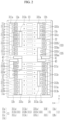
- FIG. 1 illustrates a schematic perspective view showing a rechargeable battery pack according to a first embodiment of the present disclosure
- FIG. 2 illustrates a schematic top plan view showing a rechargeable battery pack illustrated in FIG. 1
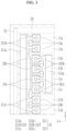
- FIG. 3 illustrates a schematic top plan view showing a first bus bar module of the rechargeable battery pack of FIG. 1
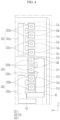
- FIG. 4 illustrates a schematic top plan view showing a second bus bar module of the rechargeable battery pack of FIG. 1 .
- the rechargeable battery pack 100 includes a cell assembly 10 including a plurality of battery cells 11 and having electrode terminals 12 each including a first electrode terminal 12a and a second electrode terminal 12b protruding upward from the respective battery cells 11 and a bus bar module 30 including a plurality of bus bars positioned at an upper portion of the cell assembly 10 and electrically connecting at least two electrode terminals 12 to each other.
- the battery cells 11 may be formed to include conventional rechargeable batteries that repeatedly perform charging and discharging operations.
- the battery cells 11 will be described by using an example in which eight battery cells 11 are electrically connected to the bus bar module 30 to form the cell assembly 10.
- the battery cells 11 may be electrically connected by the bus bar module 30 in a state in which four sets are formed by forming sets every two out of eight battery cells 11.
- the cell assembly 10 may include first to fourth sets 11a to 11d of battery cells in which eight battery cells 11 form four sets.
- a pair of battery cells 11 may be positioned in a state in which electrode terminals having the same polarity are positioned adjacent to each other.
- first to fourth sets 11a to 11d of battery cells are positioned inside a frame portion 20 with their sides adjacent to each other, and each of the first to fourth sets 11a to 11d of battery cells may be positioned in a state in which electrode terminals of different polarities are positioned adjacent to each other.
- a pair of adjacent battery cells is a first set 11a of battery cells
- another pair of battery cells adjacent to the first set 11a of battery cells is a second set 11b of battery cells
- another pair of battery cells adjacent to the second set 11b of battery cells is a third set 11c of battery cells
- a remaining pair of battery cells adjacent to the third set 11c of battery cells is a fourth set 11d of battery cells
- the first to fourth sets 11a to 11d of battery cells in which eight battery cells are arranged in four pairs, may be electrically connected to each other by the bus bar module 30 in a state of being accommodated inside the frame portion 20.
- the cell assembly 10 of the rechargeable battery pack 100 may be installed inside the frame portion 20 in a state in which two cell assemblies 10a and 10b are positioned to face each other.
- the cell assembly 10 may include a first cell assembly 10a inserted into the frame portion 20 and a second cell assembly 10b connected to the first cell assembly 10a.
- the first cell assembly 10a and the second cell assembly 10b may have a same configuration, and may be inserted into the frame portion 20 in different directions.
- same reference numbers are used for major components of the first cell assembly 10a and the second cell assembly 10b.
- a first bus bar module 31 of the first cell assembly 10a and a second bus bar module 33 of the second cell assembly 10b may be positioned on a straight line at a first side of the cell assembly 10 in a state where the first cell assembly 10a and the second cell assembly 10b are inserted into the frame portion 20.
- the second bus bar module 33 of the first cell assembly 10a and the first bus bar module 31 of the second cell assembly 10b may be positioned on a straight line with each other at a second side of the cell assembly 10.
- the frame portion 20 include a first side frame 21 supporting first sides of the battery cells 11, a second side frame 22 supporting second sides of the battery cells 11, a first end frame 23 having opposite ends respectively connected to first ends of the first side frame 21 and the second side frame 22, and a second end frame 24 having opposite ends respectively connected to second ends of the first side frame 21 and the second side frame 22.
- the first side frame 21 may be installed to support the first sides of the battery cells 11.
- the second side frame 22 may be installed to support the second sides of the battery cells 11.
- the first end frame 23 may be installed to connect between first ends of each of the first side frame 21 and the second side frame 22. That is, a first end of the first end frame 23 may be connected to a first end of the first side frame 21 by a fastening member, and a second end thereof may be connected to a first end of the second side frame 22 by the fastening member.
- the second end frame 24 may be installed to connect between second ends of each of the first side frame 21 and the second side frame 22. That is, a second end of the second end frame 24 may be connected to a first end of the first side frame 21 by the fastening member, and a second end thereof may be connected to a second end of the second side frame 22 by the fastening member.
- the cell assembly 10 may be electrically connected to the battery cells 11 by the bus bar module 30 in a state of being positioned inside the frame portion 20.
- the bus bar module 30 includes a first bus bar module 31 electrically connecting a plurality of battery cells at a first side of the cell assembly 10, and a second bus bar module 33 electrically connecting a plurality of battery cells at a second side of the cell assembly 10 in a state of being not directly connected to the first bus bar module 31.
- the first bus bar module 31 includes a plurality of bus bars electrically connecting a plurality of electrode terminals to each other at a first side edge of the cell assembly 10.
- the first bus bar module 31 may include a first bus bar 311 and a second bus bar 313 electrically connected to electrode terminals along a first side edge of the cell assembly 10.
- the first bus bar 311 and the second bus bar 313 may be positioned adjacent to the first side edge of the cell assembly 10 in a non-contact state with each other to be electrically connected to the electrode terminal 12.
- the first electrode terminal 12a may be a positive terminal
- the second electrode terminal 12b may be a negative terminal.
- the first electrode terminal 12a may be changed to a negative terminal
- the second electrode terminal 12b may be changed to a positive terminal.
- the first bus bar 311 may be positioned along a first side of the cell assembly 10, and may have a first side that is electrically connected to the first electrode terminal 12a of the first set 11a of battery cells, and a second side that is electrically connected to the second electrode terminal 12b of the fourth set 11d of battery cells.
- the first bus bar 311 may include a first body 311a positioned at upper portions of the first to fourth sets 11a, 11b, 11c, and 11d of battery cells at first sides on a first side of the cell assembly 10, a first protrusion 311b protruding from a side surface of the first body 311a at a first end and electrically connected to the first electrode terminal 12a of the first set 11a of battery cells, and a second protrusion 311c protruding from a side surface of the first body 311a at a second side and electrically connected to the second electrode terminal 12b of the fourth set 11d of battery cell.
- the first body 311a may be formed to have a long length so as to cross an upper portion of the first to fourth sets 11a to 11d of battery cells from an upper portion of a first side edge of the cell assembly 10.
- the first protrusion 311b may protrude from a side surface of the first body 311a at a first end, to be electrically connected to the first electrode terminal 12a of the first set 11a of battery cells.
- the first protrusion 311b may protrude as a pair on the side surface of the first body 311a at the first end and may be electrically connected to each of a pair of first electrode terminals 12a of the first set 11a of battery cells including two battery cells by welding or the like.
- the second protrusion 311c may protrude from a side surface of the first body 311a at a second end, to be electrically connected to a pair of second electrode terminals 12b of the fourth set 11d of battery cells.
- the second protrusion 311c may protrude as a pair on the side surface of the first body 311a at the second end and may be electrically connected to each of a pair of second electrode terminals 12b of the fourth set 11d of battery cells including two battery cells by welding or the like.
- the second bus bar 313 may be positioned at a first side edge of the cell assembly 10 at a position between the first protrusion 311b and the second protrusion 311c of the first bus bar 311.
- the second bus bar 313 may include a second body 313a positioned at upper portions of the second set 11b of battery cells and the third set battery cells 11c at a position spaced apart from the side surface of the first body 311a, a third protrusion 313b protruding from a side of the second body 313a at a first end and electrically connected to the second electrode terminal 12b of the second set 11b of battery cells, and a fourth protrusion 313c protruding from a side surface of the second body 313a at a second end and electrically connected to the first electrode terminal 12a of the third set 11c of battery cells.
- the second body 313a may be formed to have a length equal to or similar to a width of the second set 11b of battery cells and the third set 11c of battery cells, and may be positioned at upper portions of the second set 11b of battery cells and the third set 11c of battery cells at a position spaced apart from the side surface of the first body 311a.
- the third protrusion 313b may protrude from a side surface of the second body 313a at a first end, to be electrically connected to the second electrode terminals 12b of the second set 11b of battery cells.
- the third protrusion 313b may protrude as a pair at a first side of the second body 313a and may be electrically connected to each of a pair of second electrode terminals 12b of the second set 11b of battery cells including two battery cells by welding or the like.
- the fourth protrusion 313c may protrude from a side surface of the second body 313a to be electrically connected to the first electrode terminal 12a of the third set 11c of battery cells.
- the fourth protrusion 313c may protrude as a pair on the side surface of the second body 313a and may be electrically connected to each of a pair of first electrode terminals 12a of the third set 11c of battery cells including two battery cells by welding or the like.
- the second bus bar module 33 may be installed at a second side edge of the cell assembly 10, that is, at an edge position of the cell assembly 10 at a position opposite to a position where the first bus bar module 31 is installed, and includes a plurality of bus bars electrically connecting a plurality of electrode terminals to each other.
- the second bus bar module 33 may include a third bus bar 331, a fourth bus bar 333, and a fifth bus bar 335 electrically connected to the electrode terminal along the second side edge of the cell assembly 10.
- the third bus bar 331, the fourth bus bar 333, and the fifth bus bar 335 may be positioned adjacent to the second side edge of the cell assembly 10 in a non-contact state with each other to be electrically connected to the electrode terminal 12.
- the third bus bar 331 may be positioned along the a second side of the cell assembly, may have a first side that is electrically connected to the second electrode terminal 12b of the first set 11a of battery cells and a second side that is electrically connected to the first electrode terminal 12a of the second set 11b of battery cells.
- the third bus bar 331 may be formed to have a same or similar shape and size as the second bus bar 313, and may be electrically connected to the electrode terminals of the first set 11a of battery cells and the second set 11b of battery cells.
- the third bus bar 331 may include a third body 331a disposed at upper portions of the first set 11a of battery cells and the second set 11b of battery cells along the second side of the cell assembly 10, a fifth protrusion 331b protruding from the side surface of the third body 331a and electrically connected to the second electrode terminal 12b of the first set 11a of battery cells, and a sixth protrusion 331c protruding from the side surface of the third body 331a and electrically connected to the first electrode terminal 12a of the second set 11b of battery cells.
- the third body 331a may be formed to have a length equal to or similar to a length of a width of the first set 11a of battery cells and the second set 11b of battery cells, and may be positioned at upper portions of the first set 11a of battery cells and the second set 11b of battery cells at the second side edge of the cell assembly 10.
- the fifth protrusion 331b may protrude from a side surface of the third body 331a at a first end to be electrically connected to the second electrode terminal 12b of the first set 11a of battery cells.
- the fifth protrusion 331b may protrude as a pair at a first side of the third body 331a and may be electrically connected to each of a pair of first electrode terminals 12b of the first set 11a of battery cells including two battery cells by welding or the like.
- the sixth protrusion 331c may protrude from a side surface of the third body 331a at a second end to be electrically connected to the first electrode terminal 12a of the second set 11b of battery cells.
- the fourth bus bar 333 may include a fourth body 333a positioned at upper portions of the third set 11c of battery cells and the fourth set 11d of battery cells along the second side of the cell assembly 10, and a seventh protrusion 333b protruding from the side surface of the fourth body 333a and electrically connected to the second electrode terminal 12b of the third set 11c of battery cells.
- the fourth bus bar 333 may be electrically connected to electrode terminals of the third set 11c of battery cells in a state of being positioned at upper portions of the third set 11c of battery cells and the fourth set 11d of battery cells while not contacting the third bus bar 331.
- the third body 333a may be formed to have a length equal to or similar to a length of a width of the third set 11c of battery cells and the fourth set 11d of battery cells, and may be positioned at upper portions of the third set 11c of battery cells and the fourth set 11d of battery cells along the second side edge of the cell assembly 10.
- the seventh protrusion 333b may protrude as a pair at a side surface of the fourth body 333a may be electrically connected to each of a pair of second electrode terminals 12b of the third set 11c of battery cells including two battery cells by welding or the like.
- a first current collector 41 may be connected to an end portion at which the fourth set 11d of battery cells is positioned.
- the first current collector 41 is connected to the end portion of the fourth body 333a to be connected in a protruding state to the outside of the fourth set 11d of battery cells, and thus it may be installed to enable external connection for current collection and current supply.
- the fifth bus bar 335 may be positioned on the side surface of the fourth bus bar 333, and may have a first side that is electrically connected to the first electrode terminal 12a of the fourth set 11d of battery cells and a second side that extends to the outside of the fourth set 11d of battery cells.
- the fifth bus bar 335 may include a fifth body 335a spaced apart from a side surface of the fourth bus bar 333 and positioned at an upper portion of the fourth set 11d of battery cells, and an eighth protrusion 335b that protrudes from a side surface of the fifth body 335a and is electrically connected to the first electrode terminal 12a of the fourth set 11d of battery cells.
- the fifth body 335a may be formed to have a length longer than a length of the width of the fourth set 11d of battery cells, and may be installed in a state of being positioned at upper portions of the fourth set 11d of battery cells and have a first end extending to the outside of the fourth set 11d of battery cells.
- the eighth protrusion 335b may protrude from a side surface of the fifth body 335a to be electrically connected to the first electrode terminal 12a of the fourth set 11d of battery cells.
- the eighth protrusion 335b may protrude as a pair on the side surface of the fifth body 335a may be electrically connected to each of a pair of first electrode terminals 12a of the fourth set 11d of battery cells including two battery cells by welding or the like.
- a second current collector 43 may be connected to an end portion protruding from the fifth body 335a to the outside of the fourth set 11d of battery cells.
- the second current collector 43 is connected to the end portion of the fifth body 335a to be connected in a protruding state to the outside of the fourth set 11d of battery cells, and thus it may be installed to enable external connection for current collection and current supply.
- the first bus bar module 31 and the second bus bar module 33 constituting the bus bar module 30 may be installed at a first side edge position and a second side edge position of the cell assembly 10 without crossing each other in a width direction of the cell assembly 10, to be electrically connected to electrode terminals of the battery cells.
- FIG. 5 illustrates a schematic perspective view showing a rechargeable battery pack according to a second embodiment of the present disclosure
- FIG. 6 illustrates a schematic top plan view showing a rechargeable battery pack illustrated in FIG. 5
- FIG. 7 illustrates a schematic top plan view showing a first bus bar module of the rechargeable battery pack of FIG. 5
- FIG. 8 illustrates a schematic top plan view showing a second bus bar module of the rechargeable battery pack of FIG. 5 .
- the battery cells 11 may form the cell assembly 10 by electrically connecting eight battery cells 11 to the bus bar module 30.
- the battery cells 11 may be positioned such that electrode terminals of different polarities are respectively positioned at positions adjacent to each other in a state in which they are positioned adjacent to each other along a first direction.
- the battery cells 11 may include first to eighth battery cells 11A, 11B, 11C, 11D, 11E, 11F, 11G, and 11H along the first direction, each of which may be adjacently positioned such that first and second electrode terminals having different polarities may be adjacent to each other.
- the battery cells 11 are formed to include ordinary rechargeable batteries that repeatedly perform charging and discharging operations, and in the second embodiment, the battery cells 11 will be described as an example in that eight battery cells are electrically connected to the bus bar module 30 to form the cell assembly 10.
- two cell assemblies 10 may be installed inside the frame portion 20 in a state in which they are positioned to face each other.
- the cell assembly 10 may include a first cell assembly 10A inserted into the frame portion 20 and a second cell assembly 10B connected to the first cell assembly 10A.
- the first cell assembly 10A and the second cell assembly 10B may have a same configuration, and may be inserted into the frame portion 20 in different directions.
- same reference numerals are used for main components of the first cell assembly 10A and the second cell assembly 10B.
- a first bus bar module 131 of the first cell assembly 10A and a second bus bar module 133 of the second cell assembly 10B may be positioned on a straight line at a first side of the cell assembly 10 in a state where the first cell assembly 10A and the second cell assembly 10B are inserted into the frame portion 20.
- first bus bar module 131 of the first cell assembly 10A and the second bus bar module 133 of the second cell assembly 10B may be positioned on a straight line with each other at a second side of the cell assembly 10.
- the bus bar module 130 may include a first bus bar module 131 electrically connecting a plurality of battery cells at a first side of the cell assembly 10, and a second bus bar module 133 electrically connecting a plurality of battery cells at a second side of the cell assembly 10 in a state of being not directly connected to the first bus bar module 131.
- the first bus bar module 131 may include a first parallel bus bar 1311 and a second parallel bus bar 1313 electrically connected to electrode terminals along a first side of the cell assembly 10.
- the first parallel bus bar 1311 and the second parallel bus bar 1313 may be positioned adjacent to the first side edge of the cell assembly 10 in a non-contact state with each other to be electrically connected to the electrode terminal 12.
- the first electrode terminal 12a may be a positive terminal
- the second electrode terminal 12b may be a negative terminal.
- the first electrode terminal 12a may be changed to a negative terminal
- the second electrode terminal 12b may be changed to a positive terminal.
- the first parallel bus bar 1311 may be connected to respective electrode terminals of the first battery cell 11A, the third battery cell 11C, the sixth battery cell 11F, and the eighth battery cell 11H.
- the first parallel bus bar 1311 may include a first bus bar body 1311a positioned along a first side of the cell assembly 10 and positioned at upper portions of the first to eighth battery cells 11A to 11H at first sides, and a first connector 1311b, a second connector 1311c, a third connector 1311d, and a fourth connector 1311e protruding from a side surface of the first bus bar body 1311a.
- the first bus bar body 1311a may be formed to have a long length so as to cross upper portions of the first to eighth battery cells 11A to 11H at an upper portion of a first side edge of the cell assembly 10.
- the first connector 1311b may protrude from a side surface of the first bus bar body 1311a at a first end, to be electrically connected to the first electrode terminal 12a of the first battery cell 11A.
- the first connector 1311b may protrude singly from the side surface of the first bus bar body 1311a at the first end, to be electrically connected to the first electrode terminal 12a of the first battery cell 11A by welding or the like.
- the second connector 1311c may protrude from the side surface of the first bus bar body 1311a, to be electrically connected to the first electrode terminal 12a of the third battery cell 11C.
- the second connector 1311c may protrude singly from the side surface of the first bus bar body 1311a, to be electrically connected to the first electrode terminal 12a of the third battery cell 11C by welding or the like.
- the third connector 1311d may protrude from the side surface of the first bus bar body 1311a, to be electrically connected to the second electrode terminal 12b of the sixth battery cell 11F.
- the third connector 1311d may protrude singly from the side surface of the first bus bar body 1311a, to be electrically connected to the second electrode terminal 12b of the sixth battery cell 11F by welding or the like.
- the fourth connector 1311e may protrude from the side surface of the first bus bar body 1311a at a second end, to be electrically connected to the second electrode terminal 12b of the eighth battery cell 11H.
- the fourth connector 1311e may protrude singly from the side surface of the first bus bar body 1311a, to be electrically connected to the second electrode terminal 12b of the sixth battery cell 11F by welding or the like.
- the second parallel bus bar 1313 may be electrically connected to respective electrode terminals of the second battery cell 11B, the fourth battery cell 11D, the fifth battery cell 11E, and the seventh battery cell 11G at a position spaced apart from the side surface of the first parallel bus bar 1311.
- the first parallel bus bar 1313 may include a second bus bar body 1313a positioned at upper portions of the second to seventh battery cells 11B to 11G at first sides on the side surface of the first bus bar body 1311a along a first side of the cell assembly 10, and a fifth connector 1313b, a sixth connector 1313c, a seventh connector 1313d, and an eighth connector 1313e protruding from the side surface of the second bus bar body 1313a.
- the second bus bar body 1313a may be formed to have a long length so as to cross upper portions of the second to seventh battery cells 11B to 11G at a position spaced apart from the side surface of the first bus bar body 1311a at an upper portion of a first side edge of the cell assembly 10.
- the fifth connector 1313b may protrude singly from the side surface of the second bus bar body 1313a at a first end, to be electrically connected to the second electrode terminal 12b of the second battery cell 11B at a position between the first connector 1311b and the second connector 1311c by welding or the like.
- the sixth connector 1313c may protrude from the side surface of the second bus bar body 1313a, to be electrically connected to the second electrode terminal 12b of the fourth battery cell 11D at a position between the second connector 1311c and the third connector 1311d.
- the fifth connector 1313d may protrude from the side surface of the second bus bar body 1313a, to be electrically connected to the first electrode terminal 12a of the fifth battery cell 11E at a position between the second connector 1311c and the third connector 1311d.
- the eighth connector 1313e may protrude from the side surface of the second bus bar body 1313a, to be electrically connected to the first electrode terminal 12a of the seventh battery cell 11G at a position between the third connector 1311d and the fourth connector 1311e.
- the second bus bar module 133 may be installed at a second side edge of the cell assembly 10, that is, at an edge position of the cell assembly 10 at a position opposite to a position where the first bus bar module 131 is installed, and may include a plurality of bus bars electrically connecting a plurality of electrode terminals to each other.
- the second bus bar module 133 may include a third parallel bus bar 1331, a fourth parallel bus bar 1333, and a fifth parallel bus bar 1335 electrically connected to the electrode terminal along the second side of the cell assembly 10.
- the first parallel bus bar 1331 may include a third bus bar body 1331a positioned along the second side of the cell assembly 10 and positioned at upper portions of the first to fourth battery cells 11A to 11D at second sides, and a ninth connector 1331b, a tenth connector 1331c, an eleventh connector 1331d, and a twelfth connector 1331e protruding from the side surface of the third bus bar body 1331a and electrically connected to the electrode terminal.
- the third bus bar body 1331a may be formed to have a long length so as to cross upper portions of the first to fourth battery cells 11A to 11D at an upper portion of a second side edge of the cell assembly 10.
- the ninth connector 1331b may protrude singly from the side surface of the third bus bar body 1331a at the first end, to be electrically connected to the second electrode terminal 12b of the first battery cell 11A by welding or the like.
- the tenth connector 1331c may protrude from a side surface of the ninth connector 1331b to a side surface of the third bus bar body 1331a, to be electrically connected to the first electrode terminal 12a of the second battery cell 11B by welding or the like.
- the eleventh connector 1331d may protrude from a side surface of the tenth connector 1331c to the side surface of the third bus bar body 1331a, to be electrically connected to the second electrode terminal 12b of the third battery cell 11C by welding or the like.
- the twelfth connector 1331e may protrude from a side surface of the eleventh connector 1331d to the side surface of the third bus bar body 1331a, to be electrically connected to the first electrode terminal 12a of the fourth battery cell 11D by welding or the like.
- the fourth parallel bus bar 1333 may include a fourth bus bar body 1333a positioned along the second side of the cell assembly 10 and positioned at upper portions of the fifth battery cell 11E to the eighth battery cell 11H, and a 13 th connector 1333b and a 14 th connector 1333c protruding from the side surface of the fourth bus bar body 1333a.
- the fourth bus bar body 1333a may be formed to have a long length so as to cross upper portions of the fifth to eighth battery cells 11E to 11H at an upper portion of a second side edge of the cell assembly 10.
- the first current collector 41 may be connected to an end portion positioned at an upper portion of the eighth battery cell 11H from the outside of the eighth battery cell 11H.
- the 13 th connector 1333b may protrude singly from the side surface of the fourth bus bar body 1333a at a first end, to be electrically connected to the second electrode terminal 12b of the fifth battery cell 11E by welding or the like.
- the 14 th connector 1333c may protrude singly from the side surface of the fourth bus bar body 1333a, to be electrically connected to the second electrode terminal 12b of the seventh battery cell 11G by welding or the like.
- the fifth parallel bus bar 1335 may include a fifth bus bar body 1335a positioned along the second side of the cell assembly 10 and positioned at upper portions of the sixth to eighth battery cells 11F to 11H, and a 15 th connector 1335b and a 16 th connector 1335c protruding from the side surface of the fifth bus bar body 1335a.
- the fifth bus bar body 1335a may be formed to have a long length so as to cross upper portions of the sixth battery cells 11F to the eighth battery cells 11H at a position spaced apart from the side surface of the fourth bus bar body 1333a.
- the second current collector 43 may be connected to an end portion positioned at an upper portion of the eighth battery cell 11H from the outside of the eighth battery cell 11H.
- the 15 th connector 1335b may protrude from the side surface of the fifth bus bar body 1335a between the 13 th connector 1333b and the 14 th connector 1333c, to be electrically connected to the first electrode terminal 12a of the sixth battery cell 11F.
- the 16 th connector 1335c may protrude from the side surface of the fifth bus bar body 1335a, to be electrically connected to the first electrode terminal 12a of the eighth battery cell 11H.
- the first bus bar module 131 and the second bus bar module 133 constituting the bus bar module 130 may be installed at a first side edge position and a second side edge position of the cell assembly 10 without crossing each other in a width direction of the cell assembly 10, to be electrically connected to electrode terminals of the battery cells.
Landscapes
- Chemical & Material Sciences (AREA)
- Chemical Kinetics & Catalysis (AREA)
- Electrochemistry (AREA)
- General Chemical & Material Sciences (AREA)
- Connection Of Batteries Or Terminals (AREA)
- Battery Mounting, Suspending (AREA)
Applications Claiming Priority (1)
| Application Number | Priority Date | Filing Date | Title |
|---|---|---|---|
| KR1020230043657A KR20240148182A (ko) | 2023-04-03 | 2023-04-03 | 이차전지 팩 |
Publications (2)
| Publication Number | Publication Date |
|---|---|
| EP4456310A1 true EP4456310A1 (de) | 2024-10-30 |
| EP4456310B1 EP4456310B1 (de) | 2026-01-21 |
Family
ID=90364489
Family Applications (1)
| Application Number | Title | Priority Date | Filing Date |
|---|---|---|---|
| EP24162502.9A Active EP4456310B1 (de) | 2023-04-03 | 2024-03-08 | Wiederaufladbares batteriepack |
Country Status (4)
| Country | Link |
|---|---|
| US (1) | US20240332747A1 (de) |
| EP (1) | EP4456310B1 (de) |
| KR (1) | KR20240148182A (de) |
| CN (1) | CN118783044A (de) |
Cited By (1)
| Publication number | Priority date | Publication date | Assignee | Title |
|---|---|---|---|---|
| EP4421967A4 (de) * | 2022-11-17 | 2025-07-02 | Lg Energy Solution Ltd | Batteriemodul mit oberem/unterem trennbarem sammelschienenrahmen und verfahren zur montage davon |
Citations (5)
| Publication number | Priority date | Publication date | Assignee | Title |
|---|---|---|---|---|
| EP3624217A1 (de) * | 2018-09-14 | 2020-03-18 | Contemporary Amperex Technology Co., Limited | Batteriemodul und batteriepack |
| US20200212404A1 (en) * | 2017-12-19 | 2020-07-02 | Panasonic Intellectual Property Management Co., Ltd. | Busbar and battery laminate |
| US20210036296A1 (en) * | 2018-03-30 | 2021-02-04 | Sanyo Electric Co., Ltd. | Battery module, vehicle provided with same, and bus bar |
| WO2022191231A1 (ja) * | 2021-03-10 | 2022-09-15 | 株式会社Gsユアサ | 蓄電装置 |
| KR102468334B1 (ko) * | 2015-11-04 | 2022-11-16 | 삼성에스디아이 주식회사 | 이차 전지 모듈 |
-
2023
- 2023-04-03 KR KR1020230043657A patent/KR20240148182A/ko active Pending
- 2023-08-28 US US18/457,220 patent/US20240332747A1/en active Pending
-
2024
- 2024-03-08 EP EP24162502.9A patent/EP4456310B1/de active Active
- 2024-04-01 CN CN202410388258.7A patent/CN118783044A/zh active Pending
Patent Citations (5)
| Publication number | Priority date | Publication date | Assignee | Title |
|---|---|---|---|---|
| KR102468334B1 (ko) * | 2015-11-04 | 2022-11-16 | 삼성에스디아이 주식회사 | 이차 전지 모듈 |
| US20200212404A1 (en) * | 2017-12-19 | 2020-07-02 | Panasonic Intellectual Property Management Co., Ltd. | Busbar and battery laminate |
| US20210036296A1 (en) * | 2018-03-30 | 2021-02-04 | Sanyo Electric Co., Ltd. | Battery module, vehicle provided with same, and bus bar |
| EP3624217A1 (de) * | 2018-09-14 | 2020-03-18 | Contemporary Amperex Technology Co., Limited | Batteriemodul und batteriepack |
| WO2022191231A1 (ja) * | 2021-03-10 | 2022-09-15 | 株式会社Gsユアサ | 蓄電装置 |
Cited By (1)
| Publication number | Priority date | Publication date | Assignee | Title |
|---|---|---|---|---|
| EP4421967A4 (de) * | 2022-11-17 | 2025-07-02 | Lg Energy Solution Ltd | Batteriemodul mit oberem/unterem trennbarem sammelschienenrahmen und verfahren zur montage davon |
Also Published As
| Publication number | Publication date |
|---|---|
| US20240332747A1 (en) | 2024-10-03 |
| CN118783044A (zh) | 2024-10-15 |
| KR20240148182A (ko) | 2024-10-11 |
| EP4456310B1 (de) | 2026-01-21 |
Similar Documents
| Publication | Publication Date | Title |
|---|---|---|
| JP4515961B2 (ja) | 二次電池を利用した電池モジュール | |
| US11217863B2 (en) | Battery pack | |
| EP3940867B1 (de) | Batteriepack mit verbesserter struktur zur kurzschlussvermeidung und stossschutz | |
| EP3154108A1 (de) | Batteriemodul und batteriepack damit | |
| CN113381118A (zh) | 可再充电电池包 | |
| EP4456310A1 (de) | Wiederaufladbares batteriepack | |
| CN114128022A (zh) | 电池模块 | |
| EP4421955A2 (de) | Wiederaufladbares batteriemodul | |
| EP4175051B1 (de) | Sekundärbatterie | |
| KR20170028069A (ko) | 전지 모듈 | |
| US20240322390A1 (en) | Battery pack | |
| JP7802961B2 (ja) | バッテリーパック | |
| CN120261876A (zh) | 电池组件 | |
| US20210265704A1 (en) | Rechargeable battery pack | |
| EP4629429A1 (de) | Batteriemodul | |
| EP4411968A1 (de) | Sammelschiene für ein batteriemodul und batteriemodul damit | |
| EP4636939A1 (de) | Batteriezelle | |
| JP7748442B2 (ja) | 二次電池モジュール | |
| EP4411946A2 (de) | Wiederaufladbares batteriepack | |
| EP4583240A1 (de) | Taschenbatterie | |
| EP4517967A2 (de) | Batteriemodul | |
| EP4708508A1 (de) | Batteriepack und fahrzeug damit | |
| EP4614716A1 (de) | Elektrodenanordnungssatz und sekundärbatterie damit | |
| KR20240100200A (ko) | 배터리 셀 | |
| KR20250126453A (ko) | 배터리팩의 직병렬 용량 증설시 연결 편의성을 향상시킨 버스바 연결 구조 |
Legal Events
| Date | Code | Title | Description |
|---|---|---|---|
| PUAI | Public reference made under article 153(3) epc to a published international application that has entered the european phase |
Free format text: ORIGINAL CODE: 0009012 |
|
| STAA | Information on the status of an ep patent application or granted ep patent |
Free format text: STATUS: REQUEST FOR EXAMINATION WAS MADE |
|
| 17P | Request for examination filed |
Effective date: 20240308 |
|
| AK | Designated contracting states |
Kind code of ref document: A1 Designated state(s): AL AT BE BG CH CY CZ DE DK EE ES FI FR GB GR HR HU IE IS IT LI LT LU LV MC ME MK MT NL NO PL PT RO RS SE SI SK SM TR |
|
| RIN1 | Information on inventor provided before grant (corrected) |
Inventor name: KIM, HYUN |
|
| GRAP | Despatch of communication of intention to grant a patent |
Free format text: ORIGINAL CODE: EPIDOSNIGR1 |
|
| STAA | Information on the status of an ep patent application or granted ep patent |
Free format text: STATUS: GRANT OF PATENT IS INTENDED |
|
| RIC1 | Information provided on ipc code assigned before grant |
Ipc: H01M 50/507 20210101AFI20250922BHEP Ipc: H01M 50/209 20210101ALI20250922BHEP Ipc: H01M 50/509 20210101ALI20250922BHEP Ipc: H01M 50/55 20210101ALI20250922BHEP Ipc: H01M 50/503 20210101ALN20250922BHEP Ipc: H01M 50/516 20210101ALN20250922BHEP |
|
| INTG | Intention to grant announced |
Effective date: 20251008 |
|
| GRAS | Grant fee paid |
Free format text: ORIGINAL CODE: EPIDOSNIGR3 |
|
| GRAA | (expected) grant |
Free format text: ORIGINAL CODE: 0009210 |
|
| STAA | Information on the status of an ep patent application or granted ep patent |
Free format text: STATUS: THE PATENT HAS BEEN GRANTED |
|
| AK | Designated contracting states |
Kind code of ref document: B1 Designated state(s): AL AT BE BG CH CY CZ DE DK EE ES FI FR GB GR HR HU IE IS IT LI LT LU LV MC ME MK MT NL NO PL PT RO RS SE SI SK SM TR |
|
| REG | Reference to a national code |
Ref country code: CH Ref legal event code: F10 Free format text: ST27 STATUS EVENT CODE: U-0-0-F10-F00 (AS PROVIDED BY THE NATIONAL OFFICE) Effective date: 20260121 |
|
| REG | Reference to a national code |
Ref country code: DE Ref legal event code: R096 Ref document number: 602024002104 Country of ref document: DE |
|
| REG | Reference to a national code |
Ref country code: IE Ref legal event code: FG4D |
|
| PGFP | Annual fee paid to national office [announced via postgrant information from national office to epo] |
Ref country code: DE Payment date: 20260305 Year of fee payment: 3 |
|
| PGFP | Annual fee paid to national office [announced via postgrant information from national office to epo] |
Ref country code: AT Payment date: 20260301 Year of fee payment: 3 |
|
| PGFP | Annual fee paid to national office [announced via postgrant information from national office to epo] |
Ref country code: HU Payment date: 20260330 Year of fee payment: 3 |
|
| PGFP | Annual fee paid to national office [announced via postgrant information from national office to epo] |
Ref country code: FR Payment date: 20260309 Year of fee payment: 3 |