EP4411946A2 - Wiederaufladbares batteriepack - Google Patents
Wiederaufladbares batteriepack Download PDFInfo
- Publication number
- EP4411946A2 EP4411946A2 EP23212466.9A EP23212466A EP4411946A2 EP 4411946 A2 EP4411946 A2 EP 4411946A2 EP 23212466 A EP23212466 A EP 23212466A EP 4411946 A2 EP4411946 A2 EP 4411946A2
- Authority
- EP
- European Patent Office
- Prior art keywords
- bus bar
- cell
- unit battery
- holder
- cell bus
- Prior art date
- Legal status (The legal status is an assumption and is not a legal conclusion. Google has not performed a legal analysis and makes no representation as to the accuracy of the status listed.)
- Pending
Links
Images









Classifications
-
- H—ELECTRICITY
- H01—ELECTRIC ELEMENTS
- H01M—PROCESSES OR MEANS, e.g. BATTERIES, FOR THE DIRECT CONVERSION OF CHEMICAL ENERGY INTO ELECTRICAL ENERGY
- H01M50/00—Constructional details or processes of manufacture of the non-active parts of electrochemical cells other than fuel cells, e.g. hybrid cells
- H01M50/50—Current conducting connections for cells or batteries
- H01M50/528—Fixed electrical connections, i.e. not intended for disconnection
- H01M50/529—Intercell connections through partitions, e.g. in a battery casing
-
- H—ELECTRICITY
- H01—ELECTRIC ELEMENTS
- H01M—PROCESSES OR MEANS, e.g. BATTERIES, FOR THE DIRECT CONVERSION OF CHEMICAL ENERGY INTO ELECTRICAL ENERGY
- H01M50/00—Constructional details or processes of manufacture of the non-active parts of electrochemical cells other than fuel cells, e.g. hybrid cells
- H01M50/20—Mountings; Secondary casings or frames; Racks, modules or packs; Suspension devices; Shock absorbers; Transport or carrying devices; Holders
- H01M50/244—Secondary casings; Racks; Suspension devices; Carrying devices; Holders characterised by their mounting method
-
- H—ELECTRICITY
- H01—ELECTRIC ELEMENTS
- H01M—PROCESSES OR MEANS, e.g. BATTERIES, FOR THE DIRECT CONVERSION OF CHEMICAL ENERGY INTO ELECTRICAL ENERGY
- H01M50/00—Constructional details or processes of manufacture of the non-active parts of electrochemical cells other than fuel cells, e.g. hybrid cells
- H01M50/20—Mountings; Secondary casings or frames; Racks, modules or packs; Suspension devices; Shock absorbers; Transport or carrying devices; Holders
- H01M50/204—Racks, modules or packs for multiple batteries or multiple cells
-
- H—ELECTRICITY
- H01—ELECTRIC ELEMENTS
- H01M—PROCESSES OR MEANS, e.g. BATTERIES, FOR THE DIRECT CONVERSION OF CHEMICAL ENERGY INTO ELECTRICAL ENERGY
- H01M50/00—Constructional details or processes of manufacture of the non-active parts of electrochemical cells other than fuel cells, e.g. hybrid cells
- H01M50/20—Mountings; Secondary casings or frames; Racks, modules or packs; Suspension devices; Shock absorbers; Transport or carrying devices; Holders
- H01M50/204—Racks, modules or packs for multiple batteries or multiple cells
- H01M50/207—Racks, modules or packs for multiple batteries or multiple cells characterised by their shape
- H01M50/209—Racks, modules or packs for multiple batteries or multiple cells characterised by their shape adapted for prismatic or rectangular cells
-
- H—ELECTRICITY
- H01—ELECTRIC ELEMENTS
- H01M—PROCESSES OR MEANS, e.g. BATTERIES, FOR THE DIRECT CONVERSION OF CHEMICAL ENERGY INTO ELECTRICAL ENERGY
- H01M50/00—Constructional details or processes of manufacture of the non-active parts of electrochemical cells other than fuel cells, e.g. hybrid cells
- H01M50/20—Mountings; Secondary casings or frames; Racks, modules or packs; Suspension devices; Shock absorbers; Transport or carrying devices; Holders
- H01M50/289—Mountings; Secondary casings or frames; Racks, modules or packs; Suspension devices; Shock absorbers; Transport or carrying devices; Holders characterised by spacing elements or positioning means within frames, racks or packs
- H01M50/291—Mountings; Secondary casings or frames; Racks, modules or packs; Suspension devices; Shock absorbers; Transport or carrying devices; Holders characterised by spacing elements or positioning means within frames, racks or packs characterised by their shape
-
- H—ELECTRICITY
- H01—ELECTRIC ELEMENTS
- H01M—PROCESSES OR MEANS, e.g. BATTERIES, FOR THE DIRECT CONVERSION OF CHEMICAL ENERGY INTO ELECTRICAL ENERGY
- H01M50/00—Constructional details or processes of manufacture of the non-active parts of electrochemical cells other than fuel cells, e.g. hybrid cells
- H01M50/50—Current conducting connections for cells or batteries
- H01M50/502—Interconnectors for connecting terminals of adjacent batteries; Interconnectors for connecting cells outside a battery casing
- H01M50/503—Interconnectors for connecting terminals of adjacent batteries; Interconnectors for connecting cells outside a battery casing characterised by the shape of the interconnectors
-
- H—ELECTRICITY
- H01—ELECTRIC ELEMENTS
- H01M—PROCESSES OR MEANS, e.g. BATTERIES, FOR THE DIRECT CONVERSION OF CHEMICAL ENERGY INTO ELECTRICAL ENERGY
- H01M50/00—Constructional details or processes of manufacture of the non-active parts of electrochemical cells other than fuel cells, e.g. hybrid cells
- H01M50/50—Current conducting connections for cells or batteries
- H01M50/502—Interconnectors for connecting terminals of adjacent batteries; Interconnectors for connecting cells outside a battery casing
- H01M50/507—Interconnectors for connecting terminals of adjacent batteries; Interconnectors for connecting cells outside a battery casing comprising an arrangement of two or more busbars within a container structure, e.g. busbar modules
-
- H—ELECTRICITY
- H01—ELECTRIC ELEMENTS
- H01M—PROCESSES OR MEANS, e.g. BATTERIES, FOR THE DIRECT CONVERSION OF CHEMICAL ENERGY INTO ELECTRICAL ENERGY
- H01M50/00—Constructional details or processes of manufacture of the non-active parts of electrochemical cells other than fuel cells, e.g. hybrid cells
- H01M50/50—Current conducting connections for cells or batteries
- H01M50/502—Interconnectors for connecting terminals of adjacent batteries; Interconnectors for connecting cells outside a battery casing
- H01M50/514—Methods for interconnecting adjacent batteries or cells
-
- H—ELECTRICITY
- H01—ELECTRIC ELEMENTS
- H01M—PROCESSES OR MEANS, e.g. BATTERIES, FOR THE DIRECT CONVERSION OF CHEMICAL ENERGY INTO ELECTRICAL ENERGY
- H01M50/00—Constructional details or processes of manufacture of the non-active parts of electrochemical cells other than fuel cells, e.g. hybrid cells
- H01M50/50—Current conducting connections for cells or batteries
- H01M50/543—Terminals
-
- H—ELECTRICITY
- H01—ELECTRIC ELEMENTS
- H01M—PROCESSES OR MEANS, e.g. BATTERIES, FOR THE DIRECT CONVERSION OF CHEMICAL ENERGY INTO ELECTRICAL ENERGY
- H01M50/00—Constructional details or processes of manufacture of the non-active parts of electrochemical cells other than fuel cells, e.g. hybrid cells
- H01M50/50—Current conducting connections for cells or batteries
- H01M50/543—Terminals
- H01M50/547—Terminals characterised by the disposition of the terminals on the cells
- H01M50/548—Terminals characterised by the disposition of the terminals on the cells on opposite sides of the cell
-
- Y—GENERAL TAGGING OF NEW TECHNOLOGICAL DEVELOPMENTS; GENERAL TAGGING OF CROSS-SECTIONAL TECHNOLOGIES SPANNING OVER SEVERAL SECTIONS OF THE IPC; TECHNICAL SUBJECTS COVERED BY FORMER USPC CROSS-REFERENCE ART COLLECTIONS [XRACs] AND DIGESTS
- Y02—TECHNOLOGIES OR APPLICATIONS FOR MITIGATION OR ADAPTATION AGAINST CLIMATE CHANGE
- Y02E—REDUCTION OF GREENHOUSE GAS [GHG] EMISSIONS, RELATED TO ENERGY GENERATION, TRANSMISSION OR DISTRIBUTION
- Y02E60/00—Enabling technologies; Technologies with a potential or indirect contribution to GHG emissions mitigation
- Y02E60/10—Energy storage using batteries
Definitions
- the present disclosure relates to a rechargeable battery pack.
- a rechargeable battery is a battery that repeatedly performs charging and discharging, unlike a primary battery.
- a small-capacity rechargeable battery is used in a portable small electronic device such as a mobile phone, a laptop computer, or a camcorder.
- a large-capacity and high-density rechargeable battery is used as a power source for driving a motor of a hybrid vehicle or an electric vehicle or an energy storage device of the hybrid vehicle or the electric vehicle.
- the rechargeable battery includes an electrode assembly for charging and discharging a current, a case for accommodating the electrode assembly and an electrolyte, and an electrode terminal connected to the electrode assembly to draw the electrode assembly out to the outside of the case.
- the electrode assembly may be formed of a jelly roll type formed by winding an electrode and a separator.
- a plurality of unit battery cells are connected to an electrode terminal by welding in a process of manufacturing a rechargeable battery pack.
- An embodiment of the present disclosure is to provide a rechargeable battery pack in which deterioration damage due to welding does not occur by connecting an electrode terminal in a form of a cartridge without the welding.
- An embodiment of the present disclosure includes: a plurality of unit battery cells, a case in which an insertion space into which the plurality of unit battery cells are inserted is formed; and a plurality of battery holders that are installed inside the case to electrically connect the plurality of unit battery cells to each other.
- the plurality of battery holders may be installed inside the case along a first direction to electrically connect the plurality of unit battery cells to each other.
- the battery holder may include: a first holder that connects the plurality of unit battery cells to each other in the first direction in the insertion space of the case; and a second holder that connects the plurality of unit battery cells in a second direction orthogonal to the first direction at one side of the case.
- the first holder may include: first holder bodies that are installed inside the case in a state in which the first holder bodies are spaced apart from each other at equal intervals and have a plurality of first insertion portions formed in a longitudinal direction; and a plurality of first cell bus bars inserted into the plurality of first insertion portions of the first holder body and to which electrode terminals of the unit battery cells are electrically connected at opposite sides of the first holder body.
- the second holder may include: a second holder body installed at one side of an inner wall surface of the case and having a plurality of second insertion portions formed in a length direction; and a second cell bus bar inserted into the second insertion portion to be electrically connected to different electrode terminals of the plurality of unit battery cells.
- An elastic protrusion electrically connected to the electrode terminal of the unit battery cell may protrude at a portion of a surface of the first cell bus bar.
- An elastic protrusion electrically connected to the electrode terminal of the unit battery cell may protrude at a portion of a surface of the second cell bus bar.
- the rechargeable battery pack may further include a first elastic connecting plate protruding at opposite sides of the first cell bus bar to be electrically connected to the electrode terminal of the unit battery cell in a pressurized state.
- the first elastic connecting plate may include: a first elastic piece protruding from one side of the cell bus bar; and a second elastic piece protruding from the other side of the cell bus bar.
- An elastic protrusion electrically connected to the electrode terminal of the unit battery cell may protrude at a portion of a surface of the first elastic connecting plate.
- the second holder may include: the second cell bus bar installed at the one side of the inner wall surface of the case; and a second elastic connecting plate installed at one side of the second cell bus bar to be electrically connected to the different electrode terminals of the plurality of unit battery cells in a pressurized state.
- the second elastic connecting plate may include: a first connecting plate electrically connected to an electrode terminal of one unit battery cell of the plurality of unit battery cells; and a second connecting plate electrically connected to an electrode terminal of the other unit battery cell of the plurality of unit battery cells.
- the elastic protrusion electrically connected to the electrode terminal of the unit battery cell may protrude at the portion of the surface of the first elastic connecting plate and a portion of a surface of the second elastic connecting plate.
- a guide rib that guides a position where the unit battery cell is inserted into the case may protrude on a side surface of the battery holder.
- At least one of the first elastic piece and the second elastic piece may be formed with a length shorter than a height of the cell bus bar so that the portion of the surface of the cell bus bar is exposed to the outside.
- the first elastic piece and the second elastic piece may be formed with the same length in up and down directions of the opposite sides of the cell bus bar.
- Each of the first elastic piece and the second elastic piece may be formed with the length shorter than the height of the cell bus bar so that portions of surfaces of the opposite sides of the cell bus bar are exposed to the outside.
- the guide rib may include: a first rib protruding at an exposed portion of the cell bus bar and on one side surface of the cell bus bar; and a second rib protruding at an exposed portion of the cell bus bar and on the other side surface of the cell bus bar.
- the first rib and the second rib may protrude at the same height position at the opposite sides of the cell bus bar.
- the electrode terminal may include: a first electrode terminal protruding at an eccentric position of one side of the unit battery cell; and a second electrode terminal protruding at an eccentric position of the other side of the unit battery cell.
- the first electrode terminal and the second electrode terminal may protrude at the same height position on both sides of the unit battery cell.
- One of the first elastic piece and the second elastic piece may be formed with a length shorter than a height of the cell bus bar so that the portion of the surface of the cell bus bar is exposed to the outside.
- the first elastic piece and the second elastic piece may be formed of different lengths in up and down directions of the opposite sides of the cell bus bar.
- One of the first elastic piece and the second elastic piece may be formed with the length shorter than the height of the cell bus bar so that a portion of a surface of one side of the cell bus bar is exposed to the outside.
- a single guide rib may protrude at an exposed portion of the cell bus bar and on one side surface of the cell bus bar.
- the electrode terminal may include: a first electrode terminal protruding at an eccentric position of one side of the unit battery cell; and a second electrode terminal protruding at a central position of the other side of the unit battery cell.
- the first electrode terminal and the second electrode terminal may respectively protrude at different height positions on both sides of the unit battery cell.
- a connection terminal may protrude in a width direction of the unit battery cell at the battery holder.
- the battery holder may include a third holder installed at both sides opposite to inner wall surfaces of the case to electrically connect the plurality of unit battery cells.
- the third holder may include: a third holder body installed at opposite sides of the inner wall surfaces of the case and having a plurality of third insertion portions formed therein; and a plurality of third cell bus bars inserted into the plurality of third insertion portions of the third holder body and connected to different electrode terminals of the plurality of unit battery cells.
- An elastic protrusion electrically connected to the electrode terminal of the unit battery cell may protrude at a portion of a surface of the third cell bus bar.
- An electrical conductivity filler may be applied between the battery holder and the unit battery cell.
- the electrical conductivity filler may be a solder or a conductive glue film.
- a plurality of unit battery cells are electrically connected to each other in a form of a cartridge in a non-welding state by a plurality of first holders and a second holder, it is possible to improve durability by preventing deterioration damage caused by welding in a process of connecting electrode terminals.
- FIG. 1 is a perspective view schematically showing a rechargeable battery pack according to a first embodiment of the present disclosure
- FIG. 2 is a perspective view schematically showing a state in which a unit battery cell (or a single battery cell) of the rechargeable battery pack of FIG. 1 is removed.
- the rechargeable battery pack 100 includes a plurality of unit battery cells 10, a case 20 having an insertion space into which the plurality of unit battery cells 10 are inserted, and a plurality of battery holders 30 installed inside the case 20 to electrically connect the plurality of unit battery cells 10 to each other.
- the unit battery cell 10 may be a battery having a prismatic cross-section, and may include a conventional rechargeable battery that repeatedly performs charging and discharging actions.
- the unit battery cells 10 may form a plurality of rows and columns inside the case 20 to be inserted into the battery holder 30 so that the unit battery cells 10 are supported by the battery holder 30.
- the case 20 may include a bottom plate 21 supporting the unit battery cell 10 and a side surface portion 23 installed at an edge of the bottom plate 21 to support the unit battery cell 10.
- the side surface portion 23 may be integrally combined with the bottom plate 21, or the side surface portion 23 may be detachably combined with the bottom plate 21 by a bolt fastening method, a method in which a protrusion is inserted into a groove, or the like.
- the case 20 may be installed to form the insertion space with a rectangular parallelepiped into which the plurality of unit battery cells 10 are inserted.
- the plurality of unit battery cells 10 may be installed in a state in which the plurality of unit battery cells 10 are electrically connected to each other by the battery holder 30 in a state in which the plurality of unit battery cells 10 is inserted inside the case 20.
- the plurality of battery holders 30 may be installed along a first direction inside the case 20 to electrically connect the plurality of unit battery cells 10 to each other.
- the battery holder 30 may include a first holder 40 connecting the plurality of unit battery cells 10 to each other in a first direction (a y-axis direction) in the insertion space of the case 20 and a second holder 50 connecting the plurality of unit battery cells 10 in a second direction (an x-axis direction) orthogonal to the first direction (the y-axis direction) at one side of the case 20.
- the first direction (the y-axis direction) may be a transverse direction in which a plurality of first holders 40 are disposed.
- the second direction (the x-axis direction) may be a direction orthogonal to the first direction (the y-axis direction), and may be a longitudinal direction in which the plurality of unit battery cells 10 are electrically connected.
- the plurality of first holders 40 may be installed within the case 20 in a state in which the plurality of first holders 40 are spaced apart from each other at equal intervals in the first direction (the y-axis direction) to electrically connect the plurality of unit battery cells 10 to each other.
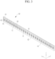
- FIG. 3 is a perspective view schematically showing the first holder according to the first embodiment of the present disclosure
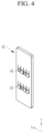
- FIG. 4 is a perspective view schematically showing a first cell bus bar inserted into a first holder body constituting the first holder of FIG. 3 .
- the first holder 40 may include first holder bodies 42 installed inside the case 20 in a state in which the first holder bodies 42 are spaced apart from each other at equal intervals and having a plurality of first insertion portions 41 formed in the second direction (the x-axis direction) for example the longitudinal direction, and a plurality of first cell bus bars 44 inserted into the plurality of first insertion portions 41 of the first holder body 42 and to which electrode terminals of the unit battery cells 10 are electrically connected at opposite sides of the first holder body 42.
- the first holder bodies 42 may be installed within the case 20 along the first direction (the y-axis direction) at equal intervals between each other, and the first holder body 42 may be formed in a long length in the second direction (the x-axis direction) orthogonal to the first direction.
- the plurality of first insertion portions 41 may be formed in a state of being spaced apart from each other along a length direction.
- the first insertion portion 41 may be formed to penetrate the first holder body 42, and the first cell bus bar 44 may be inserted in the first insertion portion 41. Therefore, the electrode terminal may be inserted into the first insertion portion 41 to be electrically connected to the first cell bus bar 44.
- the first cell bus bar 44 may electrically connect the plurality of unit battery cells 10 to each other at opposite sides of the first cell bus bar 44 in a state in which the first cell bus bar 44 is inserted into the first insertion portion 41.
- Elastic protrusions 46 may protrude on a surface of the first cell bus bar 44.
- the electrode terminal of the unit battery cell 10 is stably in close contact with the elastic protrusion 46, it is possible to improve durability of electrical connection.
- the plurality of unit battery cells 10 may be electrically connected along the first direction (the y-axis direction) by the first holder 40.
- the plurality of unit battery cells 10 may be electrically connected to each other by the second holder 50 at one side of an inner wall surface of the case 20.
- the second holder 50 may be installed to electrically connect one sides of the plurality of unit battery cells 10 electrically connected in the first direction (the y-axis direction) by the first holder 40 to each other in the second direction (the x-axis direction).
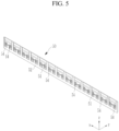
- FIG. 5 is a perspective view schematically showing the second holder according to the first embodiment of the present disclosure
- FIG. 6 is a perspective view schematically showing a second cell bus bar inserted into a second holder body constituting the second holder of FIG. 5 .
- the second holder 50 may include the second holder body 52 installed at one side of the inner wall surface of the case 20 and having a plurality of second insertion portions 51 formed in a length direction, and the second cell bus bar 54 inserted into the second insertion portion 51 to be electrically connected to different electrode terminals of the plurality of unit battery cells 10.
- the second holder body 52 may be installed at the one side of the inner wall surface of the case 20, and the plurality of second insertion portions 51 may be formed spaced apart from each other in a length direction.
- the second insertion portion 51 may be formed in a shape of a groove at the second holder body 52, and the second cell bus bar 54 may be inserted in the second insertion portion 51.
- the electrode terminal may be inserted into the second insertion portion 51 to be electrically connected to the second cell bus bar 54.
- the second cell bus bar 54 may be inserted into the second insertion portion 51 to electrically connect electrode terminals formed on one sides of a pair of unit battery cells 10 to each other.
- a plurality of elastic protrusions 46 may protrude on a surface of the second cell bus bar 54. Therefore, the electrode terminals 11 and 13 may be in close contact with the plurality of elasticity protrusions 46 to enable more stable electrical connection.
- connection terminal 60 protrudes in a width direction of the unit battery cell 10 in the battery holder 30.
- connection terminal 60 may protrude on a side surface of the battery holder 30 to be electrically connected to any one of the plurality of unit battery cells 10 connected by the battery holder 30.
- connection terminal 60 may protrude at any one of the first holder 40 and the second holder 50 constituting the battery holder 30, and may be electrically connected to an outermost cell of the plurality of unit battery cells 10.
- the plurality of unit battery cells 10 are electrically connected to each other in a form of a cartridge in a non-welding state by the plurality of first holders 40 and the second holder 50, it is possible to improve durability by preventing deterioration damage caused by welding in a process of connecting the electrode terminals.
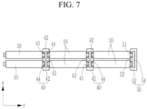
- FIG. 7 is a plane view of a main portion schematically illustrating a state in which the plurality of unit battery cells of the rechargeable battery pack according to the first embodiment of the present disclosure are connected in series by the battery holder.
- the plurality of unit battery cells 10 may be connected in series with different polarities in the first direction by the first holder 40.
- the plurality of unit battery cells 10 connected in series may be electrically connected in the second direction by the second holder 50.
- FIG. 8 is a plane view of a main portion schematically showing a state in which a plurality of unit battery cells of a rechargeable battery pack according to a second embodiment of the present disclosure are connected in parallel by a battery holder.
- electrode terminals of the same polarity of a pair of unit battery cells 10 may be electrically connected to the first holder 40 to be connected in parallel.
- a single first cell bus bar 44 may be inserted into two first insertion portions 41 to be connected to electrode terminals of two unit battery cells 10.
- the plurality of unit battery cells 10 connected in parallel may be electrically connected in the second direction by the second holder 50.
- a single second cell bus bar 54 may be inserted into two second insertion portions 51 to be connected to electrode terminals of four unit battery cells 10.
- FIG. 9 is a view of a main portion schematically showing a state in which a first elastic connecting plate protrudes at a first holder of a battery holder of a rechargeable battery pack according to a third embodiment of the present disclosure
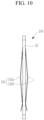
- FIG. 10 is a side view schematically showing a state in which the first elastic connecting plate protrudes at a side surface of the first holder of FIG. 9
- FIG. 11 is a side view of a main portion schematically illustrating a state in which a unit battery cell (or a single battery cell) is inserted between a plurality of first holders according to the third embodiment of the present disclosure
- FIG. 12 is a side view of a main portion schematically showing a state in which the unit battery cell of FIG. 11 is inserted between the plurality of first holders.
- the same reference numeral as that in FIGS. 1 to 8 denotes the same or similar member having the same or similar function.
- detailed description of the same reference numeral is omitted.
- a first holder 140 of the rechargeable battery pack may include the first holder body 42 and a first cell busbar 144 inserted into the first holder body 42.
- the first elastic connecting plate 142 electrically connected to the electrode terminal of the unit battery cell 10 in a pressurized state may protrude at opposite sides of a first cell bus bar 144.
- the first elastic connecting plate 142 Since the first elastic connecting plate 142 is installed in a bent state at the opposite sides of the first cell bus bar 144, the first elastic connecting plate 142 contacts the electrode terminals of the unit battery cells 10 in a pressurized state so that more stable electrical connection is possible.
- the first elastic connecting plate 142 may include a first elastic piece 142a protruding from one side of the first cell bus bar 144 and a second elastic piece 142b protruding from the other side of the first cell bus bar 144.
- the first elastic piece 142a may be formed of a metal material that has an elastic force and is electrically connected to the electrode terminal of the unit battery cell 10, and may protrude in a bent state at one side of the first cell bus bar 144.
- the first elastic piece 142a may be in close contact with the electrode terminals 11 and 13 by elastic deformation.
- the elastic protrusion 46 may protrude at a portion where the first elastic piece 142a and the electrode terminal of the unit battery cell 10 contact each other.
- the elasticity protrusion 46 may protrude on a surface of the first elastic piece 142a, and the plurality of elastic protrusions 46 may protrude at a portion where the first elastic piece 142a and the electrode terminal of the unit battery cell 10 contact each other.
- the electrode terminals 11 and 13 of the unit battery cell 10 are stably in close contact with the elastic protrusion 46, it is possible to improve durability of electrical connection.
- the second elastic piece 142b may be formed of a metal material that has an elastic force and is electrically connected to the electrode terminal of the unit battery cell 10, and may protrude in a bent state at the other side of the first cell bus bar 144.
- the second elastic piece 142b may protrude in a bent state at a position opposite to a position where the first elastic piece 142a is installed with the first cell bus bar 144 interposed between the second elastic piece 142b and the first elastic piece 142a.
- the second elastic piece 142b may be in close contact with the electrode terminals 11 and 13 by elastic deformation.
- the elastic protrusion 46 may protrude at a portion where the second elastic piece 142b and the electrode terminal of the unit battery cell 10 contact each other.
- the elasticity protrusion 46 may protrude on a surface of the second elastic piece 142b, and the plurality of elastic protrusions 46 may protrude at a portion where the second elastic piece 142b and the electrode terminal of the unit battery cell 10 contact each other.
- the plurality of unit battery cells 10 may be electrically connected to each other.
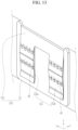
- FIG. 13 is a view of a main portion schematically showing a state in which a second elastic connecting plate protrudes at a second holder of the battery holder of the rechargeable battery pack according to the third embodiment of the present disclosure
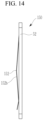
- FIG. 14 is a side view schematically showing a state in which the second elastic connecting plate protrudes at a side surface of the second holder of FIG. 13 .
- the same reference numeral as that in FIGS. 1 to 12 denotes the same or similar member having the same or similar function.
- detailed description of the same reference numeral is omitted.
- a second holder 150 may include the second holder body 52 and a second cell bus bar 154 inserted into the second holder body 52.
- the second elastic connecting plate 152 may protrude at the second cell bus bar 154.
- the second elastic connecting plate 152 may be installed at one side of the second cell bus bar 154 to be electrically connected to the different electrode terminals of the plurality of unit battery cells 10 in a pressurized state so that the plurality of unit battery cells 10 are connected in the second direction (the x-axis direction).
- the second elastic connecting plate 152 may include a first connecting plate 152a electrically connected to an electrode terminal of one unit battery cell of the plurality of unit battery cells 10, and a second connecting plate 152b electrically connected to an electrode terminal of the other unit battery cell of the plurality of unit battery cells 10.
- the first connecting plate 152a may be formed at one side of the second elastic connecting plate 152, and may be electrically connected to one electrode terminal of a pair of unit battery cells 10 to be electrically connected to each other.
- the second connecting plate 152b may be formed at the other side of the second elastic connecting plate 152, and may be electrically connected to the other electrode terminal of the pair of unit battery cells 10 to be electrically connected to each other.
- first connecting plate 152a and the second connecting plate 152b may be formed adjacent to the second cell bus bar 154 so as to connect electrode terminals of different polarities of the pair of unit battery cells 10 to each other in the second direction (the x-axis direction).
- the elastic protrusion 46 may protrude at each of the first connecting plate 152a and the second connecting plate 152b.
- the plurality of elastic protrusions 46 may protrude from surfaces of the first connecting plate 152a and the second connecting plate 152b, and may protrude so that the electrode terminal of the unit battery cell 10 is more easily electrically connected.
- FIG. 15 is a side view of a main portion schematically illustrating a state in which a guide rib protrudes at a battery holder of a rechargeable battery pack according to a fourth embodiment of the present disclosure.
- the same reference numeral as that in FIGS. 1 to 14 denotes the same or similar member having the same or similar function.
- detailed description of the same reference numeral is omitted.
- the guide rib 210 may protrude on a side surface of a first holder 240 constituting the battery holder of the rechargeable battery pack according to the fourth embodiment of the present disclosure.
- the guide rib 210 may prevent an insertion error from occurring in a process of inserting and fixing the plurality of unit battery cells 10 into the first holder 240, and may protrude on the side surface of the first holder 240.
- the guide rib 210 may include a first rib 211 protruding at one side of the first cell bus bar 44 and a second rib 213 protruding at the other side of the first cell bus bar 44.
- the first rib 211 may protrude at the one side of the first cell bus bar 44, and may protrude to prevent an insertion error of the unit battery cell 10 inserted from the one side of the first cell bus bar 44 from occurring.
- the second rib 213 may protrude to the other side of the first cell bus bar 44, and may protrude to prevent an insertion error of the unit battery cell 10 inserted from the other side of the first cell bus bar 44 from occurring.
- the first rib 211 and the second rib 213 may protrude at a lower position of the first cell bus bar 44, and may protrude on a side surface of the first cell bus bar 44 without contacting the first elastic piece 242a and the second elastic piece 242b.
- one side of each of the first elastic piece 242a and the second elastic piece 242b may be connected to an upper side of the first cell bus bar 44 and the other side of each of the first elastic piece 242a and the second elastic piece 242b may extend to a lower portion of the first cell bus bar 44 so that a portion of the side surface of the first cell bus bar 44 is exposed to the outside.
- An elastic piece 242 may include the first elastic piece 242a protruding at both sides of the first holder body 42 and the second elastic piece 242b.
- first elastic piece 242a and the second elastic piece 242b may be formed with the same length in up and down directions of opposite sides of the first cell bus bar 44, and may be formed with a length shorter than a height of the first cell bus bar 44.
- a portion of a surface of the first cell bus bar 44 may be exposed to the outside so that the guide rib 210 protrudes.
- each of the first rib 211 and the second rib 213 protrudes at an exposed portion of the first cell bus bar 44 where the first elastic piece 142a and the second elastic piece 142b are not disposed, an insertion position of the unit battery cell 10 may be guided.
- the electrode terminals 11 and 13 of the unit battery cell 10 of the fourth embodiment may protrude at an upper eccentric position with respect to a center of the unit battery cell 10, the electrode terminals 11 and 13 may interfere with the first rib 211 or the second rib 213 if an error occurs in inserting the unit battery cell 10 into the battery holder 30.
- the unit battery cell 10 may be inserted in a correct position between first holders 240 of the battery holder by an insertion guide action of the guide rib 210 so that the insertion error of the unit battery cell 10 is prevented from occurring.
- FIG. 16 is a side view of a main portion schematically illustrating a state in which a guide rib protrudes at a battery holder of a rechargeable battery pack according to a fifth embodiment of the present disclosure.
- the same reference numeral as that in FIGS. 1 to 15 denotes the same or similar member having the same or similar function.
- detailed description of the same reference numeral is omitted.
- a single guide rib 310 may protrude on one side surface of the first cell bus bar 44.
- an elastic piece 342 may include a first elastic piece 342a and a second elastic piece 342b.
- One of the first elastic piece 342a and the second elastic piece 342b may be formed with a length shorter than a height of the first cell bus bar 44 so that a portion of a surface of one side of the first cell bus bar 44 is exposed to the outside.
- the single guide rib 310 may protrude at an exposed portion of the first cell bus bar 44 where the elastic piece is not disposed on the one side surface of the first cell bus bar 44.
- the electrode terminal of the unit battery cell 10 of the fifth embodiment may include the first electrode terminal 11 protruding at an eccentric position of one side of the unit battery cell, and the second electrode terminal 13 protruding at a central position of the other side of the unit battery cell.
- the first electrode terminal 11 and the second electrode terminal 13 may respectively protrude at different height positions at both sides of the unit battery cell 10.
- the unit battery cell 10 electrically connected to the elastic piece may be inserted in a correct position in a state in which the first electrode terminal 11 is disposed at an upper side of the guide rib 310.
- the first electrode terminal 11 may interfere with the first elastic piece 342a so that the insertion error is prevented from occurring.
- FIG. 17 is a view of a main portion schematically showing a state in which an electrical conductivity filler is applied between a battery holder and an electrode terminal according to a sixth embodiment of the present disclosure.
- the same reference numeral as that in FIGS. 1 to 16 denotes the same or similar member having the same or similar function.
- detailed description of the same reference numeral is omitted.
- the electrical conductivity filler 410 may be applied between the battery holder and the electrode terminal 11 or 13.
- the present embodiment illustrates that the electrical conductivity filler 410 is applied between the first holder body 42 of the first holder 140 and the electrode terminal, but the electrical conductivity filler may be further applied between the second holder 50 and the electrode terminal.
- the electrical conductivity filler 410 may be filled between the electrode terminal 11 or 13 of the unit battery cell 10 and the first elastic connecting plate 142 of the battery holder 30, and may reduce a contact resistance between the electrode terminal 11 or 13 and the unit battery cell 10.
- the electrical conductivity filler 410 may be applied in a form of a paste between the electrode terminal and the unit battery cell, and may be a solder or a conductive glue film (or a conductive adhesive film) in the present embodiment.
- FIG. 18 is a perspective view schematically showing a rechargeable battery pack according to the sixth embodiment of the present disclosure
- FIG. 19 is a perspective view schematically showing a state in which a unit battery cell is removed from the rechargeable battery pack of FIG. 18 .
- the same reference numeral as that in FIGS. 1 to 17 denotes the same or similar member having the same or similar function.
- detailed description of the same reference numeral is omitted.
- a battery holder 450 of a rechargeable battery pack 500 may include a third holder installed at both sides opposite to inner wall surfaces of a case 420 to electrically connect the plurality of unit battery cells.
- the battery holder and the third holder use the same reference number.
- the third holder 450 may include a third holder body 452 installed at opposite sides of the inner wall surfaces of the case 420 and having a plurality of third insertion portions 451 formed therein, and a plurality of third cell bus bars 454 inserted into the plurality of third insertion portions 451 of the third holder body 452 and connected to the electrode terminal of the unit battery cell 10.
- the third holder body 452 of the sixth embodiment may be installed at the opposite sides of the case 420, and may have the plurality of third insertion portions 451 formed along a length direction.
- the plurality of third cell bus bars 454 may be installed in the plurality of third insertion portions 451 to electrically connect the plurality of unit battery cells 10 to each other.
- the elastic protrusion 46 electrically connected to the electrode terminal of the unit battery cell 10 may protrude from a surface of the third cell bus bar 454.
Landscapes
- Chemical & Material Sciences (AREA)
- Chemical Kinetics & Catalysis (AREA)
- Electrochemistry (AREA)
- General Chemical & Material Sciences (AREA)
- Connection Of Batteries Or Terminals (AREA)
- Battery Mounting, Suspending (AREA)
Applications Claiming Priority (1)
| Application Number | Priority Date | Filing Date | Title |
|---|---|---|---|
| KR1020230014491A KR20240121613A (ko) | 2023-02-02 | 2023-02-02 | 이차전지 팩 |
Publications (2)
| Publication Number | Publication Date |
|---|---|
| EP4411946A2 true EP4411946A2 (de) | 2024-08-07 |
| EP4411946A3 EP4411946A3 (de) | 2024-10-09 |
Family
ID=88978194
Family Applications (1)
| Application Number | Title | Priority Date | Filing Date |
|---|---|---|---|
| EP23212466.9A Pending EP4411946A3 (de) | 2023-02-02 | 2023-11-27 | Wiederaufladbares batteriepack |
Country Status (4)
| Country | Link |
|---|---|
| US (1) | US20240266681A1 (de) |
| EP (1) | EP4411946A3 (de) |
| KR (1) | KR20240121613A (de) |
| CN (1) | CN118431642A (de) |
Family Cites Families (3)
| Publication number | Priority date | Publication date | Assignee | Title |
|---|---|---|---|---|
| JP6327072B2 (ja) * | 2014-09-03 | 2018-05-23 | 株式会社豊田自動織機 | 電池モジュール |
| KR102740612B1 (ko) * | 2020-06-05 | 2024-12-06 | 삼성에스디아이 주식회사 | 전지 팩 |
| CN217822908U (zh) * | 2022-03-30 | 2022-11-15 | 北京卫蓝新能源科技有限公司 | 电池模组及电池包 |
-
2023
- 2023-02-02 KR KR1020230014491A patent/KR20240121613A/ko active Pending
- 2023-11-22 CN CN202311570561.0A patent/CN118431642A/zh active Pending
- 2023-11-27 EP EP23212466.9A patent/EP4411946A3/de active Pending
- 2023-12-05 US US18/529,270 patent/US20240266681A1/en active Pending
Also Published As
| Publication number | Publication date |
|---|---|
| US20240266681A1 (en) | 2024-08-08 |
| CN118431642A (zh) | 2024-08-02 |
| EP4411946A3 (de) | 2024-10-09 |
| KR20240121613A (ko) | 2024-08-09 |
Similar Documents
| Publication | Publication Date | Title |
|---|---|---|
| CN110710027B (zh) | 汇流条组件和包括该汇流条组件的电池模块 | |
| US11967736B2 (en) | Battery module comprising including chamfered inner cover and chamfered housing to prevent damage during assembly | |
| JP7050849B2 (ja) | バッテリパック | |
| US9331324B2 (en) | Connector assembly and battery pack having the same | |
| KR102409422B1 (ko) | 배터리 셀 연결용 버스 바, 배터리 팩 및 이의 제조 방법 | |
| KR100905393B1 (ko) | 이차전지 모듈 | |
| US10625619B2 (en) | Battery module, battery pack comprising battery module, and vehicle comprising battery pack | |
| US11152671B2 (en) | Battery module and battery pack including the same | |
| JP6793841B2 (ja) | バッテリーモジュール、それを含むバッテリーパック及び自動車 | |
| EP3154108B1 (de) | Batteriemodul und batteriepack damit | |
| EP2551938A1 (de) | Verbindung zwischen einem Pol und einem Gehäusedeckel in einer wiederaufladbaren Batterie | |
| EP3836246A1 (de) | Batteriemodul mit führung zur begrenzung der bewegung eines sammelschienenrahmens sowie batteriepack und fahrzeug damit | |
| EP3940867B1 (de) | Batteriepack mit verbesserter struktur zur kurzschlussvermeidung und stossschutz | |
| KR20190007745A (ko) | 배터리 팩 | |
| KR20180133698A (ko) | 배터리 모듈 | |
| CN115336098B (zh) | 电池模块、包括该电池模块的电池组以及车辆 | |
| CN113381118A (zh) | 可再充电电池包 | |
| KR20130016746A (ko) | 이차 전지 | |
| KR20210137910A (ko) | 배터리 모듈, 이러한 배터리 모듈을 포함하는 배터리 팩, 및 자동차 | |
| CN114930631A (zh) | 电池模块及包括该电池模块的电池组和车辆 | |
| KR102785764B1 (ko) | 이차 전지 | |
| EP4411946A2 (de) | Wiederaufladbares batteriepack | |
| KR102714945B1 (ko) | 배터리 모듈 및 그 제조방법 | |
| US20240332747A1 (en) | Rechargeable battery pack | |
| EP4576404A1 (de) | Batteriepack |
Legal Events
| Date | Code | Title | Description |
|---|---|---|---|
| PUAI | Public reference made under article 153(3) epc to a published international application that has entered the european phase |
Free format text: ORIGINAL CODE: 0009012 |
|
| STAA | Information on the status of an ep patent application or granted ep patent |
Free format text: STATUS: REQUEST FOR EXAMINATION WAS MADE |
|
| 17P | Request for examination filed |
Effective date: 20231127 |
|
| AK | Designated contracting states |
Kind code of ref document: A2 Designated state(s): AL AT BE BG CH CY CZ DE DK EE ES FI FR GB GR HR HU IE IS IT LI LT LU LV MC ME MK MT NL NO PL PT RO RS SE SI SK SM TR |
|
| PUAL | Search report despatched |
Free format text: ORIGINAL CODE: 0009013 |
|
| AK | Designated contracting states |
Kind code of ref document: A3 Designated state(s): AL AT BE BG CH CY CZ DE DK EE ES FI FR GB GR HR HU IE IS IT LI LT LU LV MC ME MK MT NL NO PL PT RO RS SE SI SK SM TR |
|
| RIC1 | Information provided on ipc code assigned before grant |
Ipc: H01M 50/507 20210101ALI20240903BHEP Ipc: H01M 50/503 20210101ALI20240903BHEP Ipc: H01M 50/209 20210101AFI20240903BHEP |