EP4456088A1 - Power cable with a sealed laminate water barrier - Google Patents
Power cable with a sealed laminate water barrier Download PDFInfo
- Publication number
- EP4456088A1 EP4456088A1 EP23315099.4A EP23315099A EP4456088A1 EP 4456088 A1 EP4456088 A1 EP 4456088A1 EP 23315099 A EP23315099 A EP 23315099A EP 4456088 A1 EP4456088 A1 EP 4456088A1
- Authority
- EP
- European Patent Office
- Prior art keywords
- layer
- laminate foil
- foil
- metal
- power cable
- Prior art date
- Legal status (The legal status is an assumption and is not a legal conclusion. Google has not performed a legal analysis and makes no representation as to the accuracy of the status listed.)
- Pending
Links
Images

Classifications
-
- H—ELECTRICITY
- H01—ELECTRIC ELEMENTS
- H01B—CABLES; CONDUCTORS; INSULATORS; SELECTION OF MATERIALS FOR THEIR CONDUCTIVE, INSULATING OR DIELECTRIC PROPERTIES
- H01B7/00—Insulated conductors or cables characterised by their form
- H01B7/17—Protection against damage caused by external factors, e.g. sheaths or armouring
- H01B7/28—Protection against damage caused by moisture, corrosion, chemical attack or weather
- H01B7/282—Preventing penetration of fluid, e.g. water or humidity, into conductor or cable
- H01B7/2825—Preventing penetration of fluid, e.g. water or humidity, into conductor or cable using a water impermeable sheath
Definitions
- the present invention relates to a power cable suited for dynamical submarine high voltage power cables having a sealed laminate water barrier.
- High voltage cables contain one or more electrically insulated current carrying conductors at its core section. However, intrusion of humidity or water into the core section may cause electrical breakdown of the insulation system making it vital to keep the current carrying core of high voltage power cables dry. High voltage power cables are therefore typically equipped with a circumferentially arranged water-tight layer sealing off the current carrying parts of the power cable towards ambient moisture/water.
- the water-barrier layer typically comprises a layer of a metal.
- Lead/lead-alloys are commonly applied.
- lead is a high-density materiel adding significant weight to the cable. The heavy weight induces extra costs in the entire value chain from production, under transport, storage, deployment, and when the cable is discarded after reaching its lifetime.
- Lead is also a neurotoxic material meeting increasing environmental regulation restrictions.
- lead has a relatively low fatigue resistance making leaden water barriers less suited for dynamical power cables.
- a known alternative to lead screens/water barriers is the use of high resistance metallic screens or metal polymer laminates. These screen types have a high per-unit-length resistance, which is excellent for cables in operation as induced currents are small and hence also the losses occurring in them.
- these alternative water barriers still have an unacceptable risk of failure for example because it is difficult to identify defects in production such as e.g. pinholes in the metal, bad adhesion between the layers, insufficient melting of the polymeric layers to seal the construction etc.
- EP 4 016 552 A1 discloses a lead-free water barrier suited for dynamical submarine high voltage power cables wherein the water barrier comprises a laminate structure, and wherein the laminate foil comprises a metal foil having an inner and an upper surface area, a first layer of a thermosetting semiconducting polymer laid onto the first adhesive layer, and a second layer of a thermosetting semiconducting polymer laid onto the second adhesive layer, and wherein the laminate foil is thermally joined by a heat treatment.
- the main objective of the invention is to provide a low weight water barrier suitable for high-voltage power cables.
- the present invention is based on the realisation that the exposed polymer parts of a laminate type water barrier may be safely sealed by depositing a metal layer onto at least the layers of wrapped laminate structure.
- the invention relates to a power cable comprising:
- the term "electric conductor” as used herein refers to the current carrying inner core of the power cable.
- the invention may apply any known or conceivable current carrying inner core known to the skilled person being suited to carry/transport electric current, including but not limited to a single strand of an electrically conductive material, a plurality of strands of an electrically conductive material arranged in a bunt, etc.
- the space in-between the strands of electrically conductive material may be occupied by a semiconducting filler compound.
- the electric conductor may in further example embodiments also comprise a semiconducting conductor screen arranged radially around and encompassing the single strand or bunt of strands.
- the electrically conductive material being applied as conductor(s) in power cables may advantageously have an electric conductivity of at least 4.8 ⁇ 10 6 S/m at 20 °C, preferably of at least 1.0 ⁇ 10 7 S/m at 20 °C and most preferably of at least 3.6 ⁇ 10 7 S/m at 20 °C.
- Each conductor of power cables should be individually electrically insulated. This is typically obtained by covering the surface of the conductor by a layer of an electric insulating material, i.e. to make the conductor being sheathed in the electrically insulating material.
- the invention may apply any known or conceivable material, including dielectric materials, known to the skilled person as being suited as insulation of the current carrying conductor(s) of power cables.
- the electric conductivity of the material being applied as insulation may advantageously have an electric conductivity of less than 10 -14 S/m at 20 °C, preferably less than 10 -16 S/m at 20 °C, preferably less than 10 -18 S/m at 20 °C, and most preferably less than 10 -20 S/m at 20 °C.
- Examples of materials suited for being applied to form the electric insulation of the conductor(s) include, but are not limited to; ethylene propylene rubber (EPR), ethylene propylene diene monomer (EDPM), rubber, polyethylene (EP), polypropylene (PP), polyurethane (PUR), cross-linked polyethylene (XLPE), and mass-impregnated (MI) paper.
- EPR ethylene propylene rubber
- EDPM ethylene propylene diene monomer
- EP polyethylene
- PP polypropylene
- PUR polyurethane
- XLPE cross-linked polyethylene
- MI mass-impregnated
- the term "cable core” as used herein refers to the interior part of power cables containing the electrically insulated current carrying conductor(s) of the power cable. If more than one cable core is present, the cable core usually also contains one or more spacers arranged and adapted to provide the cable core with a circular cross-section. The cable core may also further comprise signal cables, optic fibres, and/or any other component known to the skilled person suited for being located in a cable core.
- a water barrier system encapsulating said cable core means that the water barrier system is laid onto and around the outer surface of the cable core to form a watertight enclosure of the interior of the cable core preventing water and/or moisture from penetrating into the cable core.
- the water barrier system may be applied to encapsulate the cable core, alternatively encapsulating the cable core and each of the at least one electrically insulated conductors, or alternatively (only) encapsulating each of the at least one electrically insulated conductors of the power cable.
- metal foil refers to the metal layer of the laminate foil 5.
- the invention is not tied to use of any specific metal/metal alloy or thickness of the metal foil. Any metal/metal alloy at any thickness known to be suited for use in water barriers in power cables by the skilled person may be applied.
- the metal foil is either an Al/Al-alloy such as for example an AA1xxx series, an AA5xxx series or an AA6xxx series alloy according to the Aluminium Association Standard, or a Cu/Cu-alloy such as for example pure Cu, a CuNi-alloy or a CuNiSi-alloy, or a Fe/Fe-alloy, such for example stainless alloy SS316 or S32750.
- Al/Al-alloy such as for example an AA1xxx series, an AA5xxx series or an AA6xxx series alloy according to the Aluminium Association Standard
- a Cu/Cu-alloy such as for example pure Cu, a CuNi-alloy or a CuNiSi-alloy, or a Fe/Fe-alloy, such for example stainless alloy SS316 or S32750.
- the thickness of the metal foil may in an example embodiment be in one of the following ranges; from 10 to 250 ⁇ m, preferably from 15 to 200 ⁇ m, more preferably from 20 to 150 ⁇ m, more preferably from 25 to 100 ⁇ m, and most preferably from 30 to 75 ⁇ m.
- the adherence between the metal foil and the first and second thermosetting semiconducting polymer may be enhanced by applying a first adhesive laid onto and covering less than 100 %, such as from 5 to 95 % of the inner surface area of the metal foil, and a second adhesive layer laid onto and covering less than 100 %, such as from 5 to 95 % of the upper surface area of the metal foil.
- the adhesive layers are laid in-between the metal foil and the thermosetting semiconducting polymer layers.
- the term "adhesive layer laid onto and covering from 5 to 95 % of the surface area of the metal foil” as used herein refers to an adhesive applied to enhance the adherence between the metal foil and the semiconducting polymer layer.
- the adhesive is to be applied with less than complete coverage of the surface of the metal foil to enable direct contact between the metal foil and the semiconducting polymer.
- at least 5 % of the surface area of the metal foil and correspondingly the semiconducting polymer should be free of adhesive after application of the laminate foil and at least 5 % of the surface should be covered with adhesive after application of the laminate foil to ensure sufficient adhesion between the metal foil and the semiconducting polymer, i.e.
- the adhesive should cover the surface area of the metal foil in the range of from 5 to 95 %, preferably from 10 to 90 %, more preferably from 15 to 85 %, more preferably from 25 to 75 %, and most preferably from 50 to 75 %.
- the incomplete covering of the adhesive layer may be obtained by applying the adhesive in a raster pattern or in any other manner known to the skilled person.
- the invention may apply any adhesive known to the skilled person being suited for attaching a polymer layer to a metal surface.
- suited adhesives includes, but is not limited, to; epoxy resins, phenolic resins, polyurethane based glues, cyanoacrylates, acrylic glues, polyester based glues, copolymer of ethylene and ethyl acrylate, copolymer of ethylene and ethyl acrylic acid, methacrylic acid, copolymer of ethylene and glycidyl methacrylate or epoxy-based monomer such as 1,2-epoxy-1-butene, and copolymer of ethylene and maleic-anhydride.
- the above mentioned adhesives may be applied with or without electrically conductive particulates providing the glue an enhanced electric conductivity.
- thermosetting polymer as used herein means that the polymer material becomes pliable or mouldable at certain elevated temperatures and thereafter solidifies upon cooling.
- the property of being thermosetting, eventually combined with the incomplete coverage of the adhesive, provides the advantage that an improved electric contact between the metal foil and the semiconducting polymer may be achieved by a heat treatment causing the polymer to melt and then solidify in intimate contact with non-glued parts of the surface of the metal foil. This effectively reduces the electrical resistance across the metal foil/semiconducting polymer interface in these non-glued area(s).
- the thickness of the thermosetting semiconducting polymer may in an example embodiment be in one of the following ranges; from 25 to 300 ⁇ m, preferably from 35 to 200 ⁇ m, more preferably from 40 to 150 ⁇ m, more preferably from 50 to 100 ⁇ m, and most preferably from 50 to 75 ⁇ m.
- the invention may apply any thermosetting semiconductive polymer known to the skilled person being suited for use in power cables.
- suited polymers includes, but is not limited, to; a polyethylene-based material constituted of either low density polyethylene (LDPE), a linear low density polyethylene (LLDPE), a medium density polyethylene (MDPE), or a high density polyethylene (HDPE), or a copolymer of ethylene with one or more polar monomers of; acrylic acid, methacrylic acid, glycidyl methacrylate, maleic acid, or maleic anhydride.
- the polymer is made semiconducting by addition and homogenisation of 20 to 40 weight% particulate carbon in the polymer mass.
- suited particulate carbon includes but is not limited to; comminuted petrol coke, comminuted anthracite, comminuted char coal, carbon black, carbon nanotubes, etc.
- the term "wrapped around the cable core and/or the insulation system of each of the at least one conductor” as used herein refers to possible alternatives for protecting the current conducting part of the power cable from intrusion of ambient moisture/- water.
- the water barrier system according to the invention may be laid around each of the insulated current conductors and/or around the cable core containing one or more insulated current conductors.
- folded/wrapped around such that an underlaying part of the laminate foil is overlaid by an upper part of the laminate foil and leaving an outmost first or second longitudinal side-edge uncovered by the wrapped laminate structure refers to the consequence of folding/wrapping a laminate foil around a cable core and/or an insulated conductor such that opposing side-edges of the laminate fold are overlapping each other and forms a two-layered stack of laminate foil at the overlapping part and, depending on the order of folding/wrapping, makes either the first or the second longitudinal side-edge of the outermost laminate fold being uncovered and thus potentially exposed to water/moisture intrusion through the first layer of thermosetting semiconducting polymer at the overlapping part.
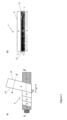
- This is schematically illustrated in e.g. figures 1a), 1b ), and 2a ), which schematically illustrates an example embodiment of a laminate foil 5 being helically wounded/wrapped around the electric insulation system 3 of an electric conductor 2.
- the helical wounding/wrapping results in a part of the deposited laminate foil (marked with the stapled box labelled with roman number I) of width w 1 is covered with the next wrapping layer (marked with the stapled box labelled with roman number II) of laminate foil leaving the first longitudinal side-edge 13 of the laminate foil "free” and thus exposed to the ambient surroundings, while the second longitudinal side-edge 14 is covered and protected by the overlaying layer of laminate foil 5.
- the first 13 or second 14 side-edge which will be the outmost "free" side-edge depends on the orientation of the helical wrapping process.
- the above described example embodiment applies a helically wrapped laminate foil in the water barrier system.
- the water barrier system may comprise a laminate foil being longitudinally folded around a cable core and/or an electric insulation system of an electric conductor.
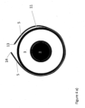
- FIG. 4a An example of the process for manufacturing such an embodiment is illustrated schematically in figures 4a ) and 4b ).
- the figures are cross-sectional cut view drawings.
- an electrically insulated 3 conductor 2 is in the process of being encapsulated by a laminate foil 5 according to the invention which is longitudinally folded around electrically insulated 3 conductor 2 the from the bottom to form the overlap at the top.
- the longitudinally folded laminate foil 5 may be folded around a cable core or around both the cable core and the electrically insulated electric conductors of the power cable.
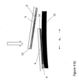
- Figure 4b is a close-up of the overlapping edges which are to be pressed down towards the underlying swelling tape 11.
- the width, w, of the laminate foil needs to be larger than the outer perimeter, p, of the cable core and/or the electrically insulated conductor to make an enclosure.
- the term “leaving an outmost first or second longitudinal side-edge uncovered by the folded/wrapped laminate foil” as used herein, refers to the fact that either of the first or second longitudinal side-edges of the laminate foil may be made the outmost edge not covered by the wrapped/folded laminate foil.
- FIG 1a An example embodiment of a typical process for forming the wrapped laminate foil 5 of the water barrier system 4 of the invention is schematically illustrated in figure 1a ).
- the wrapped laminate foil 5 of the water barrier system 4 is in the process of being applied onto a conductor 2 having an electric insulation system 3.
- the figure illustrates the process as seen from the side.
- the laminate tape has a width, indicated by double arrow marked with "w" on the figure, being approximately twice the width of the non-overlapped part of the previously deposited tape layer.
- the non-overlapped part of the previously deposited tape layer is indicated on the figure as a double arrow marked "wi".
- An advantage of applying the laminate foil in the form of a tape being helically wrapped around the cable core is, apart from the laminate foil being easy and cheap to produce, is that the tape form enables wrapping/wounding the laminate around the cable core and/or an insulated electric conductor with a tension to ensure a tight enclosure around the cable core and good contact between deposited layers of laminate foil.
- Figure 1b is a drawing illustrating an example embodiment of the laminate foil 5.
- the figure is a cut view as seen from the side taken along the stapled line marked with A-A' in figure 1a ).
- the laminate foil 5 comprises a metal foil/layer 6 of thickness t 1 and a semiconducting thermosetting polymer layer 9 of thickness t 2 (before thermosetting) on its inner surface 7.
- the ratio t 1 : t 2 may preferably be at least 0.15, more preferably at least 0.16, more preferably at least 0.17, more preferably at least 0.18, more preferably at least 0.19, more preferably at least 0.20, more preferably at least 0.30, more preferably at least 0.40, more preferably at least 0.50 and most preferably at least 1.00.
- the ratio t 1 : t 2 may be between 0.15 and 10. These thicknesses relates to before thermosetting. This difference in thickness has the advantage of obtaining the required mechanical reinforcement to make the water barrier fatigue resistant and tolerate the cable being bended without the metal foil layer becoming buckled. This feature is especially advantageous for dynamical subsea power cables.
- the metal layer 6 is made of a metal having an elastic modulus lower than 210 GPa as measured according to ASTM E111, and the layer 9 of semiconductive thermosetting polymer has an elastic modulus higher than 0.5 GPa as measured by ISO 527-1, -2 for polymers.
- This difference in elastic modulus also as the advantageous effect of obtaining the required mechanical reinforcement to make the water barrier fatigue resistant and tolerate the cable being bended without the metal foil layer becoming buckled.
- the laminate foil 5 according to the water barrier system 4 applies a metal folio/layer 6 of a thickness t 1 of a metal having an elastic modulus lower than 210 GPa as measured according to ASTM E111, and a semiconducting thermosetting polymer layer 9 of thickness t 2 and an elastic modulus higher than 0.5 GPa as measured by ISO 527-1, -2 for polymers, and wherein the ratio t 1 : t 2 may preferably be at least 0.15, more preferably at least 0.16, more preferably at least 0.17, more preferably at least 0.18, more preferably at least 0.19, more preferably at least 0.20, more preferably at least 0.30, more preferably at least 0.40, more preferably at least 0.50 and most preferably at least 1.00.
- the laminate foil 5 may further comprise a second thermosetting semiconducting polymer layer 10 laid onto the upper surface 8 of the metal foil/layer 6.
- the second thermosetting semiconducting polymer layer 10 may advantageously otherwise be equal to the first thermosetting semiconducting polymer layer 9, i.e. are made of the same material and has the same thickness t 2 as the first thermosetting semiconducting polymer layer 9.
- a metal layer is impervious to water.
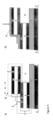
- a water barrier system 4 comprising a laminate foil 5 containing a metal layer 6 and a first 9 and optionally a second 10 polymer layer being wrapped around a cable core 1 and/or an insulated 3 conductor 2 with some overlap, has thus an excellent water barrier effect in radial direction as illustrated schematically by the white arrows in figure 2a).
- Figure 2a is a cut-view of a section including two wrapped layers of the laminate foil 5 of the embodiment shown in figure 1a ) taken along the stapled line marked with B-B' in figure 1a ).
- the two "wrappings" of the laminate foil 5 is marked with a stapled square marked with roman number I and II, respectively.
- the upper layer of the wrapped laminate foil 5, marked with the stapled box labelled with roman number II, has a side edge 13 where the first semiconducting polymer layer 9 may be exposed to ambient water/moisture. This might lead to a water intrusion into the interior part 11 due to diffusion/migration in lateral direction through the semiconducting thermosetting polymer layer 9 as indicated by the black arrow on figure 2a ).
- the water barrier system 4 of the present invention includes therefore a layer 12 of a second metal which is deposited onto the folded/wrapped laminate foil 5 and covering and thus sealing off at least the outmost first 13 or second 14 side-edge as indicated by the horizontally oriented white arrow in figure 2b ).
- the metal layer 12 may in one embodiment be deposited as a continuous metal layer completely covering the outer surface of the folded/- wrapped laminate foil 5 and thus forming a complete water barrier on top of the laminate foil preventing water intrusion in radial direction as well as in lateral direction as indicated by the white arrows in figure 3b ).
- the water barrier system further comprises a layer of a second metal deposited onto and covering at least said outermost first or second longitudinal side-edge being uncovered by the folded/wrapped laminate foil
- a layer of a second metal deposited onto and covering at least said outermost first or second longitudinal side-edge being uncovered by the folded/wrapped laminate foil means that at least the "free" longitudinal side-edge of the outmost layer of the folded/- wrapped laminate foil is covered and thus sealed off towards ambient moisture/water in the surroundings of the cable core and/or insulated electric conductor by the second metal layer.
- the embodiment shown in figures 3a) and 3b ) involves an example embodiment of the laminate foil 5 including a second semiconducting thermosetting polymer layer 10.
- the stapled line marked C-C' in figures 2a), 2b ), 3a), and 3b ) is a symmetry line indicating that the cut view should also include a "lower half' which is omitted in the figures for the sake of clarity.
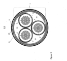
- FIG. 5 is a cut-view drawing schematically illustrating a typical construction of a three-phase power cable.
- each electric conductor 2 typically comprises a plurality of strands bundled together. Each bundle of strands is radially encapsulated by an electric insulation system 3.
- the water barrier system 4 (shown as a single layer for the sake of clarity in the figure) is laid onto the electric insulation system 3 of each conductor 2.
- the three electrically insulated and water intrusion protected conductors 2 are bundled together with three spacers 24 as shown on the figure to obtain a circular cross-section. I.e. the spacers 24 are adapted to fill the space between adjacent electrically insulated and water intrusion protected conductors 2 and provide an overall cylindrical geometry of the cable.
- Said arrangement of three conductors 2 (with insulation 3 and water protection 4) and three spacers 24 constitutes the cable core 1 as indicated by the stapled parenthesis.
- the water barrier system 4 would in this example embodiment typically be laid onto the semiconductive layer 21.
- a laminate foil 5 comprising a first metal layer/foil 6 and a first 9 and optionally a second 10 semiconducting thermosetting polymer layer 9 has the advantage that all layers of the laminate foil are electrically conductive enabling radially carrying out capacitive charges and currents induced by the electromagnetic fields of the core section of the power cable.
- the laminate foil is thermally joined by a heat treatment
- a heat treatment means that after wrapping the laminate foil 5 around the cable core 1 and/or each of the electrically insulated 3 conductor(s) 2, that the laminate foil is heat treated to a temperature at which the thermosetting semiconducting polymer layer 9, 10 melts and then cooled to the solid state. If a polyethylene based polymer is applied, the temperature treatment needs typically to increase the temperature of the laminate foil to 120 °C - 130 °C to melt the polymer.
- thermosetting heat treatment of the wrapped laminate foil may be obtained by extrusion of a third semiconducting polymer layer at an extrusion temperature of around 200 °C.
- the heat from the molten third semiconducting polymer exiting the extruder fuses the semiconducting thermosetting polymer layers 9, 10 of the laminate foil 5 below so that the adjacent semiconducting polymer layers of overlapping laminate foil edges are fused ' together and seals the water barrier.
- the heat treatment for thermally joining the laminate foil may be obtained by application of hot air, radiation (e.g. laser, IR) or induction.
- the third semiconducting polymer layer may be deposited (by extrusion) onto the wrapped laminate foil 5 after deposition of the second metal layer 12, i.e. on top of the second metal layer 12.
- the third semiconductive polymer layer may be deposited onto the wrapped laminate foil before deposition the second metal layer, and thus be laid in-between the laminate foil 5 and the second metal layer.
- semiconductor refers to an electric conductivity in the range from 10 -4 to 10 5 S/cm.
- the outer layer of the laminate foil 5, with or without a third semiconductive polymer layer applied by extrusion, is electrically conductive.
- This has the advantage of enabling depositing the second metal layer 12 by electrodeposition. This may be achieved by successively submerging and moving sections of a cable core 1 or a conductor 2 having the laminate foil and eventually a third semiconducting polymer layer thereon through an electrodeposition bath containing a dissolved metal and a galvanic anode made of the same metal as the dissolved metal of the electrodeposition bath.
- the galvanic electrode is made of Cu and the electrodeposition bath is a copper sulphate solution.
- the second metal layer may be made by electrodepositing nickel and/or cobalt.
- the electrodeposition may include use of backing plates deposited onto the folded/wrapped laminate structure, with or without a third semiconductive polymer layer to separate the semiconductive layer (and remaining insulating system) from direct contact with the electrolyte.
- the backing plates may e.g. be made of copper, nickel, or other metal.
- the invention relates to a method of forming a water barrier 4 on a cable core 1 and/or an electrically insulated 3 conductor 2 of a power cable, wherein the method comprises:
Landscapes
- Insulated Conductors (AREA)
Abstract
The present invention relates to a power cable suited for dynamical submarine high voltage power cables having a water barrier system comprising a laminate foil being folded/wrapped with an overlap and joined together around the cable core and/or the insulation system of the conductor(s) wherein the outermost laminate foil forms a longitudinal side-edge which is sealed towards the ambient by a 0.1 to 100 µm thick layer of a metal deposited onto and covering at least the longitudinal side-edge.
Description
- The present invention relates to a power cable suited for dynamical submarine high voltage power cables having a sealed laminate water barrier.
- Electrical high voltage cables contain one or more electrically insulated current carrying conductors at its core section. However, intrusion of humidity or water into the core section may cause electrical breakdown of the insulation system making it vital to keep the current carrying core of high voltage power cables dry. High voltage power cables are therefore typically equipped with a circumferentially arranged water-tight layer sealing off the current carrying parts of the power cable towards ambient moisture/water.
- The water-barrier layer typically comprises a layer of a metal. Lead/lead-alloys are commonly applied. However, lead is a high-density materiel adding significant weight to the cable. The heavy weight induces extra costs in the entire value chain from production, under transport, storage, deployment, and when the cable is discarded after reaching its lifetime. Lead is also a neurotoxic material meeting increasing environmental regulation restrictions. Furthermore, lead has a relatively low fatigue resistance making leaden water barriers less suited for dynamical power cables.
- A known alternative to lead screens/water barriers is the use of high resistance metallic screens or metal polymer laminates. These screen types have a high per-unit-length resistance, which is excellent for cables in operation as induced currents are small and hence also the losses occurring in them. However, these alternative water barriers still have an unacceptable risk of failure for example because it is difficult to identify defects in production such as e.g. pinholes in the metal, bad adhesion between the layers, insufficient melting of the polymeric layers to seal the construction etc.
-
EP 4 016 552 A1 discloses a lead-free water barrier suited for dynamical submarine high voltage power cables wherein the water barrier comprises a laminate structure, and wherein the laminate foil comprises a metal foil having an inner and an upper surface area, a first layer of a thermosetting semiconducting polymer laid onto the first adhesive layer, and a second layer of a thermosetting semiconducting polymer laid onto the second adhesive layer, and wherein the laminate foil is thermally joined by a heat treatment. - It is however, when applying laminate foil types, a risk that moisture may over time pass through the water barrier and enter the current carrying parts of the power cable by migrating through the polymer layer bonding together the wrapped and overlaid parts of the laminate type water barrier.
- The main objective of the invention is to provide a low weight water barrier suitable for high-voltage power cables.
- The present invention is based on the realisation that the exposed polymer parts of a laminate type water barrier may be safely sealed by depositing a metal layer onto at least the layers of wrapped laminate structure.
- Thus, in a first aspect, the invention relates to a power cable comprising:
- a
cable core 1 comprising at least oneconductor 2 with aninsulation system 3 with an insulation system (3) encapsulating theconductor 2, and - a water barrier system 4 encapsulating said
cable core 1 and/or saidinsulation system 3 of each of the at least oneconductor 2, - wherein
said water barrier system 4 comprises alaminate foil 5 comprising:- a
first metal layer 6 having an inner 7 and an upper 8 surface area, - a first layer of a thermosetting
semiconducting polymer 9 laid onto the inner 7 surface area of themetal foil 6, and - a first 13 and a second 14 longitudinal side-edge,
- a
- and wherein
said laminatefoil 5 is- folded/wrapped with an overlap around the
cable core 1 and/or theinsulation system 3 of each of the at least oneconductor 2 such that a part of thelaminate foil 5 is overlaid by another part of thelaminate foil 5 making an outmost first 13 or second 14 longitudinal side-edge being uncovered by the folded/wrappedlaminate foil 5, and - thermally joined by a heat treatment,
- folded/wrapped with an overlap around the
- characterised in that
the water barrier system further comprises a 0.1 to 100 µm thick layer of asecond metal 12 deposited onto and covering at least said outmost first 13 or second 14 longitudinal side-edge being uncovered by the folded/wrappedlaminate foil 5. - The term "electric conductor" as used herein refers to the current carrying inner core of the power cable. The invention may apply any known or conceivable current carrying inner core known to the skilled person being suited to carry/transport electric current, including but not limited to a single strand of an electrically conductive material, a plurality of strands of an electrically conductive material arranged in a bunt, etc. In the latter case of applying an electric conductor comprising a bunt of strands, the space in-between the strands of electrically conductive material may be occupied by a semiconducting filler compound. The electric conductor may in further example embodiments also comprise a semiconducting conductor screen arranged radially around and encompassing the single strand or bunt of strands. Examples of materials being suited as the current carrying strand(s) of the electric conductor of power cables include, but are not limited to; Cu, Cu-alloy, Al, or an Al-alloy. In practice, the electrically conductive material being applied as conductor(s) in power cables may advantageously have an electric conductivity of at least 4.8·106 S/m at 20 °C, preferably of at least 1.0·107 S/m at 20 °C and most preferably of at least 3.6·107 S/m at 20 °C.
- Each conductor of power cables should be individually electrically insulated. This is typically obtained by covering the surface of the conductor by a layer of an electric insulating material, i.e. to make the conductor being sheathed in the electrically insulating material. The invention may apply any known or conceivable material, including dielectric materials, known to the skilled person as being suited as insulation of the current carrying conductor(s) of power cables. In practice the electric conductivity of the material being applied as insulation may advantageously have an electric conductivity of less than 10-14 S/m at 20 °C, preferably less than 10-16 S/m at 20 °C, preferably less than 10-18 S/m at 20 °C, and most preferably less than 10-20 S/m at 20 °C. Examples of materials suited for being applied to form the electric insulation of the conductor(s) include, but are not limited to; ethylene propylene rubber (EPR), ethylene propylene diene monomer (EDPM), rubber, polyethylene (EP), polypropylene (PP), polyurethane (PUR), cross-linked polyethylene (XLPE), and mass-impregnated (MI) paper. The insulation effect of the insulating material depends on the thickness of the layer of insulating material. In general, the higher voltage of the electric current in the conductor, the more insulation is needed. The determination of amount of insulating material required to electrically insulate a conductor is within the ordinary skills of the person skilled in the art.
- The term "cable core" as used herein refers to the interior part of power cables containing the electrically insulated current carrying conductor(s) of the power cable. If more than one cable core is present, the cable core usually also contains one or more spacers arranged and adapted to provide the cable core with a circular cross-section. The cable core may also further comprise signal cables, optic fibres, and/or any other component known to the skilled person suited for being located in a cable core. Thus, the term "a water barrier system encapsulating said cable core" as used herein means that the water barrier system is laid onto and around the outer surface of the cable core to form a watertight enclosure of the interior of the cable core preventing water and/or moisture from penetrating into the cable core.
- According to the first aspect of the invention, the water barrier system may be applied to encapsulate the cable core, alternatively encapsulating the cable core and each of the at least one electrically insulated conductors, or alternatively (only) encapsulating each of the at least one electrically insulated conductors of the power cable.
- The term "metal foil" as used herein, refers to the metal layer of the
laminate foil 5. The invention is not tied to use of any specific metal/metal alloy or thickness of the metal foil. Any metal/metal alloy at any thickness known to be suited for use in water barriers in power cables by the skilled person may be applied. In one example embodiment, the metal foil is either an Al/Al-alloy such as for example an AA1xxx series, an AA5xxx series or an AA6xxx series alloy according to the Aluminium Association Standard, or a Cu/Cu-alloy such as for example pure Cu, a CuNi-alloy or a CuNiSi-alloy, or a Fe/Fe-alloy, such for example stainless alloy SS316 or S32750. The thickness of the metal foil (shown as curly bracket t2 infigure 1 b) ) may in an example embodiment be in one of the following ranges; from 10 to 250 µm, preferably from 15 to 200 µm, more preferably from 20 to 150 µm, more preferably from 25 to 100 µm, and most preferably from 30 to 75 µm. - In one example embodiment, the adherence between the metal foil and the first and second thermosetting semiconducting polymer may be enhanced by applying a first adhesive laid onto and covering less than 100 %, such as from 5 to 95 % of the inner surface area of the metal foil, and a second adhesive layer laid onto and covering less than 100 %, such as from 5 to 95 % of the upper surface area of the metal foil. The adhesive layers are laid in-between the metal foil and the thermosetting semiconducting polymer layers. Thus, the term "adhesive layer laid onto and covering from 5 to 95 % of the surface area of the metal foil" as used herein refers to an adhesive applied to enhance the adherence between the metal foil and the semiconducting polymer layer. In general, adhesives have relatively poor electrical conductivities such that a layer of adhesive completely covering the interface between the metal foil and the semiconducting polymer may hamper the electric conductivity in the radial direction. Thus, according to the present invention, the adhesive is to be applied with less than complete coverage of the surface of the metal foil to enable direct contact between the metal foil and the semiconducting polymer. In practice at least 5 % of the surface area of the metal foil and correspondingly the semiconducting polymer should be free of adhesive after application of the laminate foil and at least 5 % of the surface should be covered with adhesive after application of the laminate foil to ensure sufficient adhesion between the metal foil and the semiconducting polymer, i.e. the adhesive should cover the surface area of the metal foil in the range of from 5 to 95 %, preferably from 10 to 90 %, more preferably from 15 to 85 %, more preferably from 25 to 75 %, and most preferably from 50 to 75 %. The incomplete covering of the adhesive layer may be obtained by applying the adhesive in a raster pattern or in any other manner known to the skilled person.
- The invention may apply any adhesive known to the skilled person being suited for attaching a polymer layer to a metal surface. Examples of suited adhesives includes, but is not limited, to; epoxy resins, phenolic resins, polyurethane based glues, cyanoacrylates, acrylic glues, polyester based glues, copolymer of ethylene and ethyl acrylate, copolymer of ethylene and ethyl acrylic acid, methacrylic acid, copolymer of ethylene and glycidyl methacrylate or epoxy-based monomer such as 1,2-epoxy-1-butene, and copolymer of ethylene and maleic-anhydride. The above mentioned adhesives may be applied with or without electrically conductive particulates providing the glue an enhanced electric conductivity.
- The term "thermosetting polymer" as used herein means that the polymer material becomes pliable or mouldable at certain elevated temperatures and thereafter solidifies upon cooling. The property of being thermosetting, eventually combined with the incomplete coverage of the adhesive, provides the advantage that an improved electric contact between the metal foil and the semiconducting polymer may be achieved by a heat treatment causing the polymer to melt and then solidify in intimate contact with non-glued parts of the surface of the metal foil. This effectively reduces the electrical resistance across the metal foil/semiconducting polymer interface in these non-glued area(s). The thickness of the thermosetting semiconducting polymer (before thermosetting) may in an example embodiment be in one of the following ranges; from 25 to 300 µm, preferably from 35 to 200 µm, more preferably from 40 to 150 µm, more preferably from 50 to 100 µm, and most preferably from 50 to 75 µm.
- The invention may apply any thermosetting semiconductive polymer known to the skilled person being suited for use in power cables. Examples of suited polymers includes, but is not limited, to; a polyethylene-based material constituted of either low density polyethylene (LDPE), a linear low density polyethylene (LLDPE), a medium density polyethylene (MDPE), or a high density polyethylene (HDPE), or a copolymer of ethylene with one or more polar monomers of; acrylic acid, methacrylic acid, glycidyl methacrylate, maleic acid, or maleic anhydride. The polymer is made semiconducting by addition and homogenisation of 20 to 40 weight% particulate carbon in the polymer mass. Examples of suited particulate carbon includes but is not limited to; comminuted petrol coke, comminuted anthracite, comminuted char coal, carbon black, carbon nanotubes, etc.
- The term "wrapped around the cable core and/or the insulation system of each of the at least one conductor" as used herein refers to possible alternatives for protecting the current conducting part of the power cable from intrusion of ambient moisture/- water. The water barrier system according to the invention may be laid around each of the insulated current conductors and/or around the cable core containing one or more insulated current conductors.
- The term "folded/wrapped around such that an underlaying part of the laminate foil is overlaid by an upper part of the laminate foil and leaving an outmost first or second longitudinal side-edge uncovered by the wrapped laminate structure" as used herein refers to the consequence of folding/wrapping a laminate foil around a cable core and/or an insulated conductor such that opposing side-edges of the laminate fold are overlapping each other and forms a two-layered stack of laminate foil at the overlapping part and, depending on the order of folding/wrapping, makes either the first or the second longitudinal side-edge of the outermost laminate fold being uncovered and thus potentially exposed to water/moisture intrusion through the first layer of thermosetting semiconducting polymer at the overlapping part. This is schematically illustrated in e.g.
figures 1a), 1b ), and2a ), which schematically illustrates an example embodiment of alaminate foil 5 being helically wounded/wrapped around theelectric insulation system 3 of anelectric conductor 2. - As seen on e.g.
figure 1a ) or2a ), the helical wounding/wrapping results in a part of the deposited laminate foil (marked with the stapled box labelled with roman number I) of width w1 is covered with the next wrapping layer (marked with the stapled box labelled with roman number II) of laminate foil leaving the first longitudinal side-edge 13 of the laminate foil "free" and thus exposed to the ambient surroundings, while the second longitudinal side-edge 14 is covered and protected by the overlaying layer oflaminate foil 5. Which of the first 13 or second 14 side-edge which will be the outmost "free" side-edge depends on the orientation of the helical wrapping process. Infigure 1a ) the wrapping process proceeds from left to the right (on the figure), this makes the first side-edge 13 being the outmost "free" side-edge. However, if the wrapping process was made to proceed in the opposite direction, it would be the second side-edge 14 which would be the outmost "free" side-edge. - The above described example embodiment applies a helically wrapped laminate foil in the water barrier system. In another example embodiment, the water barrier system may comprise a laminate foil being longitudinally folded around a cable core and/or an electric insulation system of an electric conductor.
- An example of the process for manufacturing such an embodiment is illustrated schematically in
figures 4a ) and4b ). The figures are cross-sectional cut view drawings. As seen onfigure 4a ), an electrically insulated 3conductor 2 is in the process of being encapsulated by alaminate foil 5 according to the invention which is longitudinally folded around electrically insulated 3conductor 2 the from the bottom to form the overlap at the top. In this example embodiment, there is a swellingtape 11 laid onto theinsulation system 3 of theconductor 2. Alternatively, the longitudinally foldedlaminate foil 5 may be folded around a cable core or around both the cable core and the electrically insulated electric conductors of the power cable.Figure 4b ) is a close-up of the overlapping edges which are to be pressed down towards the underlying swellingtape 11. In this example embodiment, the width, w, of the laminate foil needs to be larger than the outer perimeter, p, of the cable core and/or the electrically insulated conductor to make an enclosure. The overlap width, wi, is in this case: wi = w - p, such that the overlap may easily be made relatively large by simply applying a wider laminate structure. - Thus, the term "leaving an outmost first or second longitudinal side-edge uncovered by the folded/wrapped laminate foil" as used herein, refers to the fact that either of the first or second longitudinal side-edges of the laminate foil may be made the outmost edge not covered by the wrapped/folded laminate foil.
- An example embodiment of a typical process for forming the wrapped
laminate foil 5 of the water barrier system 4 of the invention is schematically illustrated infigure 1a ). In this example embodiment, the wrappedlaminate foil 5 of the water barrier system 4 is in the process of being applied onto aconductor 2 having anelectric insulation system 3. The figure illustrates the process as seen from the side. As seen on the figure the laminate tape has a width, indicated by double arrow marked with "w" on the figure, being approximately twice the width of the non-overlapped part of the previously deposited tape layer. The non-overlapped part of the previously deposited tape layer is indicated on the figure as a double arrow marked "wi". An advantage of applying the laminate foil in the form of a tape being helically wrapped around the cable core is, apart from the laminate foil being easy and cheap to produce, is that the tape form enables wrapping/wounding the laminate around the cable core and/or an insulated electric conductor with a tension to ensure a tight enclosure around the cable core and good contact between deposited layers of laminate foil. -
Figure 1b ) is a drawing illustrating an example embodiment of thelaminate foil 5. The figure is a cut view as seen from the side taken along the stapled line marked with A-A' infigure 1a ). In this example embodiment, thelaminate foil 5 comprises a metal foil/layer 6 of thickness t1 and a semiconductingthermosetting polymer layer 9 of thickness t2 (before thermosetting) on itsinner surface 7. - In one embodiment, the ratio t1 : t2 may preferably be at least 0.15, more preferably at least 0.16, more preferably at least 0.17, more preferably at least 0.18, more preferably at least 0.19, more preferably at least 0.20, more preferably at least 0.30, more preferably at least 0.40, more preferably at least 0.50 and most preferably at least 1.00. In another embodiment, the ratio t1 : t2 may be between 0.15 and 10. These thicknesses relates to before thermosetting. This difference in thickness has the advantage of obtaining the required mechanical reinforcement to make the water barrier fatigue resistant and tolerate the cable being bended without the metal foil layer becoming buckled. This feature is especially advantageous for dynamical subsea power cables.
- In another the example embodiment, the
metal layer 6 is made of a metal having an elastic modulus lower than 210 GPa as measured according to ASTM E111, and thelayer 9 of semiconductive thermosetting polymer has an elastic modulus higher than 0.5 GPa as measured by ISO 527-1, -2 for polymers. This difference in elastic modulus also as the advantageous effect of obtaining the required mechanical reinforcement to make the water barrier fatigue resistant and tolerate the cable being bended without the metal foil layer becoming buckled. - In a further example embodiment, the
laminate foil 5 according to the water barrier system 4 applies a metal folio/layer 6 of a thickness t1 of a metal having an elastic modulus lower than 210 GPa as measured according to ASTM E111, and a semiconductingthermosetting polymer layer 9 of thickness t2 and an elastic modulus higher than 0.5 GPa as measured by ISO 527-1, -2 for polymers, and wherein the ratio t1 : t2 may preferably be at least 0.15, more preferably at least 0.16, more preferably at least 0.17, more preferably at least 0.18, more preferably at least 0.19, more preferably at least 0.20, more preferably at least 0.30, more preferably at least 0.40, more preferably at least 0.50 and most preferably at least 1.00. - In one embodiment, the
laminate foil 5 may further comprise a second thermosettingsemiconducting polymer layer 10 laid onto theupper surface 8 of the metal foil/layer 6. The second thermosettingsemiconducting polymer layer 10 may advantageously otherwise be equal to the first thermosettingsemiconducting polymer layer 9, i.e. are made of the same material and has the same thickness t2 as the first thermosettingsemiconducting polymer layer 9. - A metal layer is impervious to water. A water barrier system 4 comprising a
laminate foil 5 containing ametal layer 6 and a first 9 and optionally a second 10 polymer layer being wrapped around acable core 1 and/or an insulated 3conductor 2 with some overlap, has thus an excellent water barrier effect in radial direction as illustrated schematically by the white arrows infigure 2a). Figure 2a ) is a cut-view of a section including two wrapped layers of thelaminate foil 5 of the embodiment shown infigure 1a ) taken along the stapled line marked with B-B' infigure 1a ). The two "wrappings" of thelaminate foil 5 is marked with a stapled square marked with roman number I and II, respectively. As seen onfigure 2a ), water/moisture diffusing/migrating in radial direction through the outer sheathings/layers (not shown on the figure) of the power cable is effectively prevented from penetrating into the interior 11 part containing theelectric conductor 2 and itselectrical insulation system 3 by themetal layer 6 of thelaminate foil 5 of the water barrier system 4. - However, the upper layer of the wrapped
laminate foil 5, marked with the stapled box labelled with roman number II, has aside edge 13 where the firstsemiconducting polymer layer 9 may be exposed to ambient water/moisture. This might lead to a water intrusion into theinterior part 11 due to diffusion/migration in lateral direction through the semiconductingthermosetting polymer layer 9 as indicated by the black arrow onfigure 2a ). The water barrier system 4 of the present invention includes therefore alayer 12 of a second metal which is deposited onto the folded/wrappedlaminate foil 5 and covering and thus sealing off at least the outmost first 13 or second 14 side-edge as indicated by the horizontally oriented white arrow infigure 2b ). Themetal layer 12 may in one embodiment be deposited as a continuous metal layer completely covering the outer surface of the folded/- wrappedlaminate foil 5 and thus forming a complete water barrier on top of the laminate foil preventing water intrusion in radial direction as well as in lateral direction as indicated by the white arrows infigure 3b ). - Thus, the term "the water barrier system further comprises a layer of a second metal deposited onto and covering at least said outermost first or second longitudinal side-edge being uncovered by the folded/wrapped laminate foil" as used herein, means that at least the "free" longitudinal side-edge of the outmost layer of the folded/- wrapped laminate foil is covered and thus sealed off towards ambient moisture/water in the surroundings of the cable core and/or insulated electric conductor by the second metal layer.
- The embodiment shown in
figures 3a) and 3b ) involves an example embodiment of thelaminate foil 5 including a second semiconductingthermosetting polymer layer 10. - The stapled line marked C-C' in
figures 2a), 2b ),3a), and 3b ) is a symmetry line indicating that the cut view should also include a "lower half' which is omitted in the figures for the sake of clarity. -
Figure 5 is a cut-view drawing schematically illustrating a typical construction of a three-phase power cable. As seen on the figure, eachelectric conductor 2 typically comprises a plurality of strands bundled together. Each bundle of strands is radially encapsulated by anelectric insulation system 3. In this example embodiment, the water barrier system 4 (shown as a single layer for the sake of clarity in the figure) is laid onto theelectric insulation system 3 of eachconductor 2. The three electrically insulated and water intrusion protectedconductors 2 are bundled together with threespacers 24 as shown on the figure to obtain a circular cross-section. I.e. thespacers 24 are adapted to fill the space between adjacent electrically insulated and water intrusion protectedconductors 2 and provide an overall cylindrical geometry of the cable. Said arrangement of three conductors 2 (withinsulation 3 and water protection 4) and threespacers 24 constitutes thecable core 1 as indicated by the stapled parenthesis. Typically, there will be asemiconductive layer 21 onto the cable core to conduct capacitive charges induced in the cable, anarmoring 22 and anouter polymer sheathing 23. In the case of applying the water barrier system 4 according to the invention on thecable core 1, the water barrier system 4 would in this example embodiment typically be laid onto thesemiconductive layer 21. - The use of a
laminate foil 5 comprising a first metal layer/foil 6 and a first 9 and optionally a second 10 semiconductingthermosetting polymer layer 9 has the advantage that all layers of the laminate foil are electrically conductive enabling radially carrying out capacitive charges and currents induced by the electromagnetic fields of the core section of the power cable. - The term "the laminate foil is thermally joined by a heat treatment" as used herein means that after wrapping the
laminate foil 5 around thecable core 1 and/or each of the electrically insulated 3 conductor(s) 2, that the laminate foil is heat treated to a temperature at which the thermosettingsemiconducting polymer layer - In one embodiment, the thermosetting heat treatment of the wrapped laminate foil may be obtained by extrusion of a third semiconducting polymer layer at an extrusion temperature of around 200 °C. The heat from the molten third semiconducting polymer exiting the extruder fuses the semiconducting
thermosetting polymer layers laminate foil 5 below so that the adjacent semiconducting polymer layers of overlapping laminate foil edges are fused ' together and seals the water barrier. In other example embodiments, the heat treatment for thermally joining the laminate foil may be obtained by application of hot air, radiation (e.g. laser, IR) or induction. The third semiconducting polymer layer may be deposited (by extrusion) onto the wrappedlaminate foil 5 after deposition of thesecond metal layer 12, i.e. on top of thesecond metal layer 12. Alternatively, the third semiconductive polymer layer may be deposited onto the wrapped laminate foil before deposition the second metal layer, and thus be laid in-between thelaminate foil 5 and the second metal layer. - The term "semiconducting" as used herein refers to an electric conductivity in the range from 10-4 to 105 S/cm.
- The outer layer of the
laminate foil 5, with or without a third semiconductive polymer layer applied by extrusion, is electrically conductive. This has the advantage of enabling depositing thesecond metal layer 12 by electrodeposition. This may be achieved by successively submerging and moving sections of acable core 1 or aconductor 2 having the laminate foil and eventually a third semiconducting polymer layer thereon through an electrodeposition bath containing a dissolved metal and a galvanic anode made of the same metal as the dissolved metal of the electrodeposition bath. Then by applying a voltage to the outer conducting layer of thecable core 1 or theconductor 2 being moved through the bath and the galvanic anode which makes the said outer conducting layer acting as a cathode, dissolved metal ions in the electrodeposition bath will be reduced and deposit as a metal layer onto the outer surface of the part of thecable core 1 or theconductor 2 which is passing through the electrodeposition bath. - In the case of making a
second metal layer 12 in copper, the galvanic electrode is made of Cu and the electrodeposition bath is a copper sulphate solution. Alternatively, the second metal layer may be made by electrodepositing nickel and/or cobalt. - In one embodiment, the electrodeposition may include use of backing plates deposited onto the folded/wrapped laminate structure, with or without a third semiconductive polymer layer to separate the semiconductive layer (and remaining insulating system) from direct contact with the electrolyte. The backing plates may e.g. be made of copper, nickel, or other metal.
- In a second aspect, the invention relates to a method of forming a water barrier 4 on a
cable core 1 and/or an electrically insulated 3conductor 2 of a power cable, wherein the method comprises: - applying a
laminate foil 5 comprising:- a
first metal layer 6 having an inner 7 and an upper 8 surface area, - a first layer of a thermosetting
semiconducting polymer 9 laid onto the inner 7 surface area of themetal foil 6, and - a first 13 and a second 14 longitudinal side-edge,
- a
- folding/wrapping the
laminate foil 5 with an overlap around either thecable core 1 and/or theinsulation system 3 of each of the at least oneconductor 2 such that a part of thelaminate foil 5 is overlaid by another part of thelaminate foil 5 making an outmost first 13 or second 14 longitudinal side-edge being uncovered by the folded/wrappedlaminate foil 5, and - either:
- thermosetting said wrapped
laminate foil 5 by heating it to a temperature of 150 to 200 °C, and - depositing by electrodeposition a 0.1 to 100 µm thick layer of a
second metal 12 onto said third semiconducting polymer layer to at least covering the outmost first 13 or second 14 longitudinal side-edge of the folded/wrapped laminate foil,
- thermosetting said wrapped
- or:
- depositing by electrodeposition a 0.1 to 100 µm thick layer of a
second metal 12 onto the folded/wrappedlaminate foil 5, and - thermosetting said wrapped
laminate foil 5 by heating it to a temperature of 150 - 200 °C. - thermosetting said wrapped
laminate foil 5 by extruding at an extrusion temperature of around 200 °C a third semiconducting polymer layer onto the said wrappedlaminate foil 5,
- depositing by electrodeposition a 0.1 to 100 µm thick layer of a
-
-
Figure 1a ) is a drawing schematically illustrating as seen from the side of a an electrically insulated conductor being covered with an example embodiment of a laminate foil being part of the water barrier system according to the invention. -
Figure 1b ) is a cut view drawing as seen from the side taken along the stapled line marked as A - A' onfigure 1a ), and which schematically illustrates the stratigraphic structure of the example embodiment of the laminate foil shown infigure 1a ). -
Figure 2a ) is a cut view taken along the stapled line marked as B - B' onfigure 1a ) as seen from the side of a section of the electrically insulated conductor having the laminate foil being part of the water barrier system according to the invention. -
Figure 2b ) is a cut view illustrating the same example embodiment as shown infigure 2a ) but after deposition of a second metal layer completing the water barrier system according to the invention. -
Figures 3a) and 3b ) are cut views showing a similar embodiment as shown infigures 2a) and 2b ), but with a laminate foil containing a semiconducting polymer film on both sides of the first metal layer. -
Figures 4a ) is a cross-sectional cut view drawing illustrating a process for manufacturing a water-barrier system according to the invention around a conductor. -
Figure 4b ) is a cut-view drawing showing a close-up of the overlapping edges shown infigure 4a ). -
Figure 5 is a cut view drawing illustrating the typical construction of a three-phase power cable.
Claims (18)
1. A power cable comprising:
a cable core (1) comprising at least one conductor (2) with an insulation system (3) encapsulating the conductor (2), and
a water barrier system (4) encapsulating said cable core (1) and/or said insulation system (3) of each of the at least one conductor (2),
wherein
said water barrier system (4) comprises a laminate foil (5) comprising:
said water barrier system (4) comprises a laminate foil (5) comprising:
- a first metal layer (6) having an inner (7) and an upper (8) surface area,
- a first layer of a thermosetting semiconducting polymer (9) laid onto the inner (7) surface area of the metal foil (6), and
- a first (13) and a second (14) longitudinal side-edge,
and wherein
said laminate foil (5) is
said laminate foil (5) is
- folded/wrapped with an overlap around the cable core (1) and/or the insulation system (3) of each of the at least one conductor (2) such that a part of the laminate foil (5) is overlaid by another part of the laminate foil (5) making an outmost first (13) or second (14) longitudinal side-edge being uncovered by the folded/wrapped laminate foil (5), and
- thermally joined by a heat treatment,
characterised in that
the water barrier system further comprises a 0.1 to 100 µm thick layer of a second metal (12) deposited onto and covering at least said outmost first (13) or second (14) longitudinal side-edge being uncovered by the folded/wrapped laminate foil (5).
the water barrier system further comprises a 0.1 to 100 µm thick layer of a second metal (12) deposited onto and covering at least said outmost first (13) or second (14) longitudinal side-edge being uncovered by the folded/wrapped laminate foil (5).
2. The power cable according to claim 1, wherein the first metal layer (6) is either:
aluminium,
an aluminium alloy of the AA1xxx series,AA5xxx series or the AA6xxx series according to the Aluminium Association Standard,
copper
a copper-alloy
a CuNi-alloy
a CuNiSi-alloy,
iron
a Fe-alloy
stainless steel alloy SS316 or
stainless steel alloy S32750.
3. The power cable according to claim 1 or 2, wherein the thickness, t1, of the first metal layer (6) is in one of the following ranges; from 10 to 250 µm, preferably from 15 to 200 µm, more preferably from 20 to 150 µm, more preferably from 25 to 100 µm, more preferably from 30 to 75 µm, and most preferably from 15 to 20 µm.
4. The power cable according to any preceding claim, wherein the laminate foil (5) further comprises a second semiconducting thermosetting polymer layer (10) laid onto the upper (8) surface of the metal layer (6).
5. The power cable according to claim 3 or 4, wherein the thickness, t2, of the first (9) and if present, the second (10) semiconducting thermosetting polymer layer is adapted to make the ratio t1 : t2 to be at least 0.15, more preferably at least 0.16, more preferably at least 0.17, more preferably at least 0.18, more preferably at least 0.19, more preferably at least 0.20, more preferably at least 0.30, more preferably at least 0.40, more preferably at least 0.50 and most preferably at least 1.00, where the thickness t2 is before thermosetting the laminate foil (5).
5. The power cable according to any preceding claim, wherein the laminate foil (5) further comprises a first adhesive laid onto the inner (7) surface area of the metal foil/layer (6) and a second adhesive layer laid onto the upper (8) surface area of the metal foil/layer (6), and wherein the first and the second adhesive layers, after wrapping of the laminate structure, cover less than 100 %, such as from 5 to 95 %, preferably from 10 to 90 %, more preferably from 15 to 85 %, more preferably from 25 to 75 %, and most preferably from 50 to 75 % of the surface area (7, 8) of the metal foil/layer (6).
6. The power cable according to claim 5, wherein the adhesive of the first and or second adhesive layer is chosen from one of: epoxy resins, phenolic resins, polyurethane based glues, cyanoacrylates, acrylic glues, polyester based glues, copolymer of ethylene and ethyl acrylate, copolymer of ethylene and ethyl acrylic acid, methacrylic acid, copolymer of ethylene and glycidyl methacrylate or epoxy-based monomer such as 1,2-epoxy-1-butene, and copolymer of ethylene and maleic-anhydride.
7. The power cable according to any of claims 5 or 6, wherein the adhesive of the first and or second adhesive layer contains electrically conductive particles.
8. The power cable according to any preceding claim, wherein the first (9) and the second (10) layer of a semiconducting thermosetting polymer is chosen from one of: a low density polyethylene (LDPE), a linear low density polyethylene (LLDPE), a medium density polyethylene (MDPE), or a high density polyethylene (HDPE), or a copolymer of ethylene with one or more polar monomers of; acrylic acid, methacrylic acid, glycidyl methacrylate, maleic acid, or maleic anhydride.
9. The power cable according to claim 8, wherein the first (9) and the second (10) layer of semiconducting thermosetting polymer contains from 20 to 40 weight% particulate carbon in the polymer mass chosen from one of; comminuted petrol coke, comminuted anthracite, comminuted char coal, carbon black, or carbon nanotubes.
10. The power cable according to any preceding claim, wherein one or both of the semiconducting thermosetting polymer layers (9, 10) further comprises a second polymer layer of polyethylene-terephthalate, PET, or a polyester.
11. The power cable according to any preceding claim, wherein the water barrier system (4) further comprises an third semiconducting polymer layer laid either directly onto the laminate foil (5) or onto the second metal layer (12) by extrusion at an extrusion temperature of around 200 °C.
12. The power cable according to claim 11, wherein the polymer material of the third semiconducting polymer layer contains until 40 weight% particulate carbon in the polymer mass, and where the particulate carbon is one of; comminuted petrol coke, comminuted anthracite, comminuted char coal, carbon black, or carbon nanotubes.
13. The power cable according to any preceding claim, wherein the first metal layer (6) is made of a metal having an elastic modulus lower than 210 GPa as measured according to ASTM E111, and the polymer of the first (9) and eventually the second (10) semiconductive thermosetting layer(s) has/have an elastic modulus higher than 0.5 GPa as measured by ISO 527-1, -2 for polymers.
14. The power cable according to any preceding claim, wherein the second metal layer (12) is made of one of Co, Cu, or Ni.
15. The power cable according to any preceding claim, wherein the layer of second metal (12) covering and encapsulating the folded/wrapped laminate foil (5).
16. A method of forming a water barrier (4) on either a cable core (1) or an electrically insulated (3) conductor (2) of a power cable according to first aspect of the invention, wherein the method comprises:
providing a laminate foil (5) comprising:
- a first metal layer (6) having an inner (7) and an upper (8) surface area,
- a first layer of a thermosetting semiconducting polymer (9) laid onto the inner (7) surface area of the metal foil (6),
- a first 13 and a second 14 longitudinal side-edge,
folding/wrapping the laminate foil (5) with an overlap around either the cable core (1) and/or the insulation system (3) of each of the at least one conductor (2) such that a part of the laminate foil (5) is overlaid by another part of the laminate foil (5) making an outmost first (13) or second (14) longitudinal side-edge being uncovered by the folded/wrapped laminate foil (5), and
either:
- thermosetting said folded/wrapped laminate foil (5) by heating it to a temperature of 150 to 200 °C, and
- depositing by electrodeposition a 0.1 to 100 µm thick layer (12) of a second metal onto the folded/wrapped laminate foil to cover at least the outmost first (13) or second (14) longitudinal side-edge being uncovered by the folded/wrapped laminate foil (5),
or:
- depositing by electrodeposition a 0.1 to 100 µm thick layer of a second metal (12) onto the folded/wrapped laminate foil to cover at least the outmost first (13) or second (14) longitudinal side-edge being uncovered by the folded/wrapped laminate foil (5), and
- thermosetting said wrapped laminate foil (5) by extruding at an extrusion temperature of around 200 °C a third semiconducting polymer layer onto the folded/wrapped laminate foil (5) including the deposited layer (12) of a second metal.
17. A method according to claim 16, wherein the layer of second metal (12) is deposited to cover and encapsulating the folded/wrapped laminate foil (5).
Priority Applications (1)
| Application Number | Priority Date | Filing Date | Title |
|---|---|---|---|
| EP23315099.4A EP4456088A1 (en) | 2023-04-24 | 2023-04-24 | Power cable with a sealed laminate water barrier |
Applications Claiming Priority (1)
| Application Number | Priority Date | Filing Date | Title |
|---|---|---|---|
| EP23315099.4A EP4456088A1 (en) | 2023-04-24 | 2023-04-24 | Power cable with a sealed laminate water barrier |
Publications (1)
| Publication Number | Publication Date |
|---|---|
| EP4456088A1 true EP4456088A1 (en) | 2024-10-30 |
Family
ID=86387110
Family Applications (1)
| Application Number | Title | Priority Date | Filing Date |
|---|---|---|---|
| EP23315099.4A Pending EP4456088A1 (en) | 2023-04-24 | 2023-04-24 | Power cable with a sealed laminate water barrier |
Country Status (1)
| Country | Link |
|---|---|
| EP (1) | EP4456088A1 (en) |
Citations (4)
| Publication number | Priority date | Publication date | Assignee | Title |
|---|---|---|---|---|
| GB1246245A (en) * | 1970-02-26 | 1971-09-15 | Standard Telephones Cables Ltd | Cables |
| WO2015067323A1 (en) * | 2013-11-11 | 2015-05-14 | Prysmian S.P.A. | Process of manufacturing power cables and related power cable |
| EP4016552A1 (en) | 2020-12-15 | 2022-06-22 | Nexans | Lead-free water barrier |
| EP4141893A1 (en) * | 2021-08-25 | 2023-03-01 | Nexans | Radially and longitudinally conductive water barrier assembly |
-
2023
- 2023-04-24 EP EP23315099.4A patent/EP4456088A1/en active Pending
Patent Citations (4)
| Publication number | Priority date | Publication date | Assignee | Title |
|---|---|---|---|---|
| GB1246245A (en) * | 1970-02-26 | 1971-09-15 | Standard Telephones Cables Ltd | Cables |
| WO2015067323A1 (en) * | 2013-11-11 | 2015-05-14 | Prysmian S.P.A. | Process of manufacturing power cables and related power cable |
| EP4016552A1 (en) | 2020-12-15 | 2022-06-22 | Nexans | Lead-free water barrier |
| EP4141893A1 (en) * | 2021-08-25 | 2023-03-01 | Nexans | Radially and longitudinally conductive water barrier assembly |
Similar Documents
| Publication | Publication Date | Title |
|---|---|---|
| US11631505B2 (en) | CuNiSi alloy cable sheathing | |
| EP4016552B1 (en) | Lead-free water barrier | |
| EP4015208B1 (en) | Laminate water barrier | |
| US3340353A (en) | Double-shielded electric cable | |
| US5043538A (en) | Water resistant cable construction | |
| US3206541A (en) | Sheathed electrical cable | |
| US4322574A (en) | Cable shielding tape and cable | |
| US3321572A (en) | Dual laminated telephone cable sheath | |
| US9892824B2 (en) | Method of manufacturing power cables | |
| JP2023121142A (en) | Power cable with composite water barrier | |
| US12136503B2 (en) | Low resistance polyethylene sheath with combined adhesive and mechanical properties | |
| US3629489A (en) | Cable sheathing | |
| US20180047481A1 (en) | Water-tight power cable with metallic screen rods | |
| EP4141893A1 (en) | Radially and longitudinally conductive water barrier assembly | |
| EP4462451A1 (en) | Power cable with lead-free metal water barrier | |
| JP2008071641A (en) | Rubber or plastic insulated power cable | |
| EP4386783A1 (en) | Composite water barrier | |
| JP2590702Y2 (en) | Waterproof shielding composite tape and waterproof type power cable using the same | |
| US20250174375A1 (en) | Method for producing a power cable with a water barrier and a method for jointing a first and second power cable | |
| JPH0412566B2 (en) | ||
| JP2004178869A (en) | Connection method and connection part of laminate tape for cable | |
| CN121528621A (en) | A flexible busbar for power transmission |
Legal Events
| Date | Code | Title | Description |
|---|---|---|---|
| PUAI | Public reference made under article 153(3) epc to a published international application that has entered the european phase |
Free format text: ORIGINAL CODE: 0009012 |
|
| STAA | Information on the status of an ep patent application or granted ep patent |
Free format text: STATUS: THE APPLICATION HAS BEEN PUBLISHED |
|
| AK | Designated contracting states |
Kind code of ref document: A1 Designated state(s): AL AT BE BG CH CY CZ DE DK EE ES FI FR GB GR HR HU IE IS IT LI LT LU LV MC ME MK MT NL NO PL PT RO RS SE SI SK SM TR |
|
| STAA | Information on the status of an ep patent application or granted ep patent |
Free format text: STATUS: REQUEST FOR EXAMINATION WAS MADE |
|
| 17P | Request for examination filed |
Effective date: 20250428 |