EP4456023A1 - Paper sheet handling device - Google Patents
Paper sheet handling device Download PDFInfo
- Publication number
- EP4456023A1 EP4456023A1 EP21968932.0A EP21968932A EP4456023A1 EP 4456023 A1 EP4456023 A1 EP 4456023A1 EP 21968932 A EP21968932 A EP 21968932A EP 4456023 A1 EP4456023 A1 EP 4456023A1
- Authority
- EP
- European Patent Office
- Prior art keywords
- partition member
- bank bill
- pusher
- stopper
- pusher plate
- Prior art date
- Legal status (The legal status is an assumption and is not a legal conclusion. Google has not performed a legal analysis and makes no representation as to the accuracy of the status listed.)
- Pending
Links
Images













Classifications
-
- B—PERFORMING OPERATIONS; TRANSPORTING
- B65—CONVEYING; PACKING; STORING; HANDLING THIN OR FILAMENTARY MATERIAL
- B65H—HANDLING THIN OR FILAMENTARY MATERIAL, e.g. SHEETS, WEBS, CABLES
- B65H31/00—Pile receivers
- B65H31/24—Pile receivers multiple or compartmented, e.d. for alternate, programmed, or selective filling
-
- B—PERFORMING OPERATIONS; TRANSPORTING
- B65—CONVEYING; PACKING; STORING; HANDLING THIN OR FILAMENTARY MATERIAL
- B65H—HANDLING THIN OR FILAMENTARY MATERIAL, e.g. SHEETS, WEBS, CABLES
- B65H1/00—Supports or magazines for piles from which articles are to be separated
- B65H1/04—Supports or magazines for piles from which articles are to be separated adapted to support articles substantially horizontally, e.g. for separation from top of pile
- B65H1/06—Supports or magazines for piles from which articles are to be separated adapted to support articles substantially horizontally, e.g. for separation from top of pile for separation from bottom of pile
-
- B—PERFORMING OPERATIONS; TRANSPORTING
- B65—CONVEYING; PACKING; STORING; HANDLING THIN OR FILAMENTARY MATERIAL
- B65H—HANDLING THIN OR FILAMENTARY MATERIAL, e.g. SHEETS, WEBS, CABLES
- B65H31/00—Pile receivers
- B65H31/30—Arrangements for removing completed piles
- B65H31/3036—Arrangements for removing completed piles by gripping the pile
- B65H31/3045—Arrangements for removing completed piles by gripping the pile on the outermost articles of the pile for clamping the pile
-
- B—PERFORMING OPERATIONS; TRANSPORTING
- B65—CONVEYING; PACKING; STORING; HANDLING THIN OR FILAMENTARY MATERIAL
- B65H—HANDLING THIN OR FILAMENTARY MATERIAL, e.g. SHEETS, WEBS, CABLES
- B65H31/00—Pile receivers
- B65H31/30—Arrangements for removing completed piles
- B65H31/3054—Arrangements for removing completed piles by moving the surface supporting the lowermost article of the pile, e.g. by using belts or rollers
- B65H31/3063—Arrangements for removing completed piles by moving the surface supporting the lowermost article of the pile, e.g. by using belts or rollers by special supports like carriages, containers, trays, compartments, plates or bars, e.g. moved in a closed loop
-
- B—PERFORMING OPERATIONS; TRANSPORTING
- B65—CONVEYING; PACKING; STORING; HANDLING THIN OR FILAMENTARY MATERIAL
- B65H—HANDLING THIN OR FILAMENTARY MATERIAL, e.g. SHEETS, WEBS, CABLES
- B65H31/00—Pile receivers
- B65H31/30—Arrangements for removing completed piles
- B65H31/3081—Arrangements for removing completed piles by acting on edge of the pile for moving it along a surface, e.g. by pushing
-
- B—PERFORMING OPERATIONS; TRANSPORTING
- B65—CONVEYING; PACKING; STORING; HANDLING THIN OR FILAMENTARY MATERIAL
- B65H—HANDLING THIN OR FILAMENTARY MATERIAL, e.g. SHEETS, WEBS, CABLES
- B65H83/00—Combinations of piling and depiling operations, e.g. performed simultaneously, of interest apart from the single operation of piling or depiling as such
- B65H83/02—Combinations of piling and depiling operations, e.g. performed simultaneously, of interest apart from the single operation of piling or depiling as such performed on the same pile or stack
-
- G—PHYSICS
- G07—CHECKING-DEVICES
- G07D—HANDLING OF COINS OR VALUABLE PAPERS, e.g. TESTING, SORTING BY DENOMINATIONS, COUNTING, DISPENSING, CHANGING OR DEPOSITING
- G07D11/00—Devices accepting coins; Devices accepting, dispensing, sorting or counting valuable papers
- G07D11/10—Mechanical details
- G07D11/12—Containers for valuable papers
- G07D11/13—Containers for valuable papers with internal means for handling valuable papers
-
- B—PERFORMING OPERATIONS; TRANSPORTING
- B65—CONVEYING; PACKING; STORING; HANDLING THIN OR FILAMENTARY MATERIAL
- B65H—HANDLING THIN OR FILAMENTARY MATERIAL, e.g. SHEETS, WEBS, CABLES
- B65H2301/00—Handling processes for sheets or webs
- B65H2301/40—Type of handling process
- B65H2301/42—Piling, depiling, handling piles
- B65H2301/422—Handling piles, sets or stacks of articles
- B65H2301/4223—Pressing piles
-
- B—PERFORMING OPERATIONS; TRANSPORTING
- B65—CONVEYING; PACKING; STORING; HANDLING THIN OR FILAMENTARY MATERIAL
- B65H—HANDLING THIN OR FILAMENTARY MATERIAL, e.g. SHEETS, WEBS, CABLES
- B65H2301/00—Handling processes for sheets or webs
- B65H2301/40—Type of handling process
- B65H2301/42—Piling, depiling, handling piles
- B65H2301/422—Handling piles, sets or stacks of articles
- B65H2301/4224—Gripping piles, sets or stacks of articles
- B65H2301/42242—Gripping piles, sets or stacks of articles by acting on the outermost articles of the pile for clamping the pile
-
- B—PERFORMING OPERATIONS; TRANSPORTING
- B65—CONVEYING; PACKING; STORING; HANDLING THIN OR FILAMENTARY MATERIAL
- B65H—HANDLING THIN OR FILAMENTARY MATERIAL, e.g. SHEETS, WEBS, CABLES
- B65H2301/00—Handling processes for sheets or webs
- B65H2301/40—Type of handling process
- B65H2301/42—Piling, depiling, handling piles
- B65H2301/422—Handling piles, sets or stacks of articles
- B65H2301/4226—Delivering, advancing piles
- B65H2301/42266—Delivering, advancing piles by acting on edge of the pile for moving it along a surface, e.g. pushing
-
- B—PERFORMING OPERATIONS; TRANSPORTING
- B65—CONVEYING; PACKING; STORING; HANDLING THIN OR FILAMENTARY MATERIAL
- B65H—HANDLING THIN OR FILAMENTARY MATERIAL, e.g. SHEETS, WEBS, CABLES
- B65H2405/00—Parts for holding the handled material
- B65H2405/10—Cassettes, holders, bins, decks, trays, supports or magazines for sheets stacked substantially horizontally
- B65H2405/11—Parts and details thereof
- B65H2405/115—Cover
-
- B—PERFORMING OPERATIONS; TRANSPORTING
- B65—CONVEYING; PACKING; STORING; HANDLING THIN OR FILAMENTARY MATERIAL
- B65H—HANDLING THIN OR FILAMENTARY MATERIAL, e.g. SHEETS, WEBS, CABLES
- B65H2405/00—Parts for holding the handled material
- B65H2405/30—Other features of supports for sheets
- B65H2405/33—Compartmented support
- B65H2405/332—Superposed compartments
-
- B—PERFORMING OPERATIONS; TRANSPORTING
- B65—CONVEYING; PACKING; STORING; HANDLING THIN OR FILAMENTARY MATERIAL
- B65H—HANDLING THIN OR FILAMENTARY MATERIAL, e.g. SHEETS, WEBS, CABLES
- B65H2405/00—Parts for holding the handled material
- B65H2405/30—Other features of supports for sheets
- B65H2405/35—Means for moving support
- B65H2405/353—Means for moving support vertically
-
- B—PERFORMING OPERATIONS; TRANSPORTING
- B65—CONVEYING; PACKING; STORING; HANDLING THIN OR FILAMENTARY MATERIAL
- B65H—HANDLING THIN OR FILAMENTARY MATERIAL, e.g. SHEETS, WEBS, CABLES
- B65H2701/00—Handled material; Storage means
- B65H2701/10—Handled articles or webs
- B65H2701/19—Specific article or web
- B65H2701/1912—Banknotes, bills and cheques or the like
-
- G—PHYSICS
- G07—CHECKING-DEVICES
- G07D—HANDLING OF COINS OR VALUABLE PAPERS, e.g. TESTING, SORTING BY DENOMINATIONS, COUNTING, DISPENSING, CHANGING OR DEPOSITING
- G07D2211/00—Paper-money handling devices
Definitions
- the present invention relates to a paper sheet handling apparatus.
- a member such as a plate and belt that partitions a storage space for a bank bill into upper and lower portions is arranged in a recharging machine, an automated teller machine (ATM), or the like.
- ATM automated teller machine
- an apparatus including a pair of upper and lower conveying belts that sandwiches and conveys a bank bill is known (See, for example, JP H7-220139 A ).
- an apparatus including an upper surface guide and a stage driven by a driving force of a common drive motor is also known (See, for example, JP 2018-032341 A ) .
- a plurality of partition members that can ascend and descend may be arranged to partition a storage space for a paper sheet such as a bank bill into upper and lower portions.
- the plurality of partition members are, for example, a partition member on which the paper sheet is placed, a partition member that presses the paper sheet placed on another partition member positioned below downward, a partition member arranged above the paper sheet to form a storage space at a predetermined height, and the like.
- a plurality of drive sources that drive the partition members are arranged.
- arranging the plurality of drive sources results in a larger apparatus and also makes it difficult to reduce the costs.
- An object of the present invention is to provide a paper sheet handling apparatus capable of raising and lowering the plurality of partition members to the plurality of predetermined positions with a simple configuration.
- a paper sheet handling apparatus includes: a plurality of partition members having a first partition member and a second partition member arranged below the first partition member, the plurality of partition members being capable of ascending and descending to form a storage space for a paper sheet; a guide fixed to the first partition member and extending downward; a first stopper that is in contact with the first partition member at a lower limit position of the first partition member; and a pressing portion that is fixed to the second partition member and raises and lowers the first partition member integrally with the second partition member using a frictional force generated by pressing the guide, in which the guide has a recessed portion that cancels the frictional force, the second partition member descends integrally with the first partition member, and after the first partition member comes into contact with the first stopper, the second partition member descends independently of the first partition member against the frictional force to a position where the pressing portion faces the recessed portion, and the second partition member, when ascending from a position where the pressing portion faces the recessed portion to a position where the pressing portion
- the plurality of partition members can be raised and lowered to the plurality of predetermined positions with the simple configuration.
- FIG. 1 is a left side view illustrating an internal structure of the bank bill processing machine 100.
- the up-down, front-back, and left-right directions illustrated in FIG. 1 and FIGS. 2A to 13 to be described later are merely an example of a case where a customer side of the bank bill processing machine 100 is the front direction, but for example, the up-down direction is a vertical direction, and the front-back direction and the left-right direction are horizontal directions.
- the bank bill processing machine 100 illustrated in FIG. 1 is, for example, an ATM, a bill recycle unit (BRU), a cash dispenser (CD), a teller cash recycler (TCR), or the like, and includes a bank bill deposit/withdrawal unit 10, a discrimination unit 20, a primary holding unit 30, a rejection unit 40, an intermediate conveying unit 50, and a plurality of storage cassettes 60.
- the bank bill processing machine 100 is an example of a paper sheet handling apparatus, but the paper sheet handling apparatus may be any apparatus as long as it conveys or performs some processing on a paper sheet including a bank bill B as an example, and thus the paper sheet handling apparatus can be regarded as, for example, only the bank bill deposit/withdrawal unit 10.
- the bank bill deposit/withdrawal unit 10 is provided at the upper portion of the front end of a guide mechanism 1, and is where the bank bill B to be deposited is inserted and the bank bill B to be withdrawn is ejected.
- the discrimination unit 20 is arranged below the bank bill deposit/withdrawal unit 10 and determines authenticity, contamination, a folded corner, and the like of the bank bill B conveyed from the bank bill deposit/withdrawal unit 10.
- the primary holding unit 30 temporarily stores the bank bill B and the like that are conveyed from the bank bill deposit/withdrawal unit 10 to the discrimination unit 20 and determined to be normal at the discrimination unit 20.
- the rejection unit 40 stores an unreturned bank bill B among the bank bills B determined to be abnormal at the discrimination unit 20.
- the intermediate conveying unit 50 conveys the bank bill B in the front-back direction between the discrimination unit 20 and the plurality of storage cassettes 60.
- the plurality of storage cassettes 60 store, for example, the bank bills B of different denominations.
- the storage cassettes 60 can eject the stored bank bills B.
- the bank bills B stored in the storage cassettes 60 are thus used for withdrawal.
- FIG. 2A to 2C are left side views illustrating an internal structure of the bank bill processing machine 100 for explaining first deposit processing, second deposit processing, and withdrawal processing.
- the bank bill B inserted into the bank bill deposit/withdrawal unit 10 is conveyed to the discrimination unit 20. Then, the bank bill B determined to be normal at the discrimination unit 20 is conveyed to the primary holding unit 30.
- the bank bill B determined to be abnormal at the discrimination unit 20 (such as a bogus bank bill) is returned to the bank bill deposit/withdrawal unit 10.
- the bank bill B temporarily stored in the primary holding unit 30 is conveyed through the discrimination unit 20 and the intermediate conveying unit 50 and conveyed to each storage cassette 60.
- the bank bill B stored in each storage cassette 60 is ejected to the bank bill deposit/withdrawal unit 10 by the intermediate conveying unit 50 and the discrimination unit 20.
- the bank bill B determined to be abnormal by the discrimination unit 20 among the bank bills B stored in each storage cassette 60 is conveyed to the primary holding unit 30 or the rejection unit 40.
- FIG. 3 is a left side view illustrating the internal structure of the bank bill deposit/withdrawal unit 10.
- the bank bill deposit/withdrawal unit 10 includes a roof 11 (an example of a first partition member), a pusher plate 12 (an example of a second partition member), a pusher 13 (an example of a third partition member), a stage 14, a shuttle 15, a push-in wall 16, a receiving unit 17, and a sending unit 18.
- the bank bill deposit/withdrawal unit 10 further includes two guides 2, two pressing portions 3, a movable member 4, a timing belt 5, a tension spring 6, and two rails 7 (see FIG. 10 ).
- the plate-shaped roof 11 first partition member
- the pusher plate 12 second partition member
- the pusher 13 third partition member
- the partition member is not limited to a plate-shaped member, and may be, for example, a member having a roller, a belt, or the like and capable of conveying the bank bill B.
- the roof 11 is arranged so as to be capable of ascending and descending.
- the pusher plate 12 is arranged below the roof 11.
- the pusher plate 12 is arranged so as to be capable of ascending and descending, and receives the bank bill B to be returned from the receiving unit 17 among the bank bills B sent from the stage 14 by the sending unit 18.
- the pusher 13 is arranged below the pusher plate 12.
- the pusher 13 is arranged so as to be capable of ascending and descending, and can press the bank bill B on the stage 14 from above.
- a plurality of entry prevention members 13a that prevent the bank bill B from entering from below the pusher 13 are arranged on the pusher 13 with a space therebetween in the left-right direction so as to hang downward.
- the stage 14 is arranged so as to be capable of ascending and descending, and as illustrated in FIG. 3 , the bank bills B to be withdrawn or the bank bills B to be deposited are stacked on the stage 14. Note that the stage 14 ascends and descends due to driving of a drive unit (for example, a motor) different from a drive unit that raises and lowers the pusher 13.
- a drive unit for example, a motor
- the shuttle 15 has, for example, a pair of upper and lower conveying belts capable of sandwiching the bank bill B, and moves in the front-back direction between a front position at the time of the deposit and withdrawal of the bank bill B (see the solid line in FIG. 3 ) and a back position at which the bank bill B is received and passed from and to the stage 14 (see the dotted line in FIG. 3 ).
- a stopper 15a is provided at the back end of the shuttle 15 to prevent the bank bill B from falling backward from the shuttle 15.
- the stopper 15a rotates to a position where a space between the back ends of the pair of upper and lower conveying belts of the shuttle 15 is opened (see the solid line in FIG. 3 ) and a position where the space is closed (see the dotted line in FIG. 3 ).
- the push-in wall 16 is arranged to be movable in the front-back direction, and pushes the bank bill B on the stage 14 forward toward the shuttle 15 at the time of withdrawal (moves from the position of the solid line to the position of the dotted line in FIG. 3 ).
- the receiving unit 17 has, for example, an impeller and a roller.
- the receiving unit 17 receives the bank bill B to be withdrawn toward the stage 14 and receives the bank bill B to be returned toward the pusher plate 12.
- the sending unit 18 has, for example, a roller, a separator roller, or the like.
- the sending unit 18 sends the deposited bank bill B toward the discrimination unit 20 from the stage 14 that has descended below the position illustrated in FIG. 3 (see the dotted arrow in FIG. 3 ).
- FIGS. 4A to 4I are left side views illustrating the internal structure of the bank bill deposit/withdrawal unit 10 for explaining the operation at the time of deposition.
- the bank bill B is inserted between the pair of upper and lower conveying belts of the shuttle 15.
- the roof 11, the pusher plate 12, the pusher 13, and the stage 14 are at initial positions P11, P21, P31, and P41, respectively.
- the roof 11, the pusher plate 12, and the pusher 13 are in close contact with each other at these initial positions, but the stage 14 is positioned below the pusher 13 with a space therebetween to form the storage space for the bank bill B.
- the shuttle 15 moves backward toward the stage 14 while sandwiching the bank bill B. After the shuttle 15 moves backward, the pair of conveying belts of the shuttle 15 conveys the bank bill B onto the stage 14.
- the shuttle 15 moves slightly forward once, and the stopper 15a rotates to the position where the space between the back ends of the pair of upper and lower conveying belts is closed.
- the roof 11 and the pusher plate 12 descends to lower limit positions P12 and P22 spaced apart from each other, and the pusher 13 descends to a pressing position P32 where the pusher 13 presses the bank bill B on the stage 14 that has descended to a sending position P42 from above.
- the sending unit 18 sends the bank bill B on the stage 14 toward the discrimination unit 20 (see the dotted arrow in FIG. 4E ).
- a rejected bank bill B (RJ) determined to be abnormal by the discrimination unit 20 among the bank bills B sent by the sending unit 18 is returned to the bank bill deposit/withdrawal unit 10 as illustrated in the conveyance route R2 indicated by the bold dotted arrow in FIG. 2A described above, and received onto the pusher plate 12 from the receiving unit 17.
- the pusher 13 ascends toward a rejected bank bill ejection position P33, and the stopper 15a rotates to the position where the space between the back ends of the pair of upper and lower conveying belts is opened.
- the push-in wall 16 returns backward, and the stopper 15a rotates to the position where the space between the back ends of the pair of upper and lower conveying belts is closed.
- the shuttle 15 moves forward, and the pair of upper and lower conveying belts ejects the rejected bank bill B (RJ) forward of the bank bill deposit/withdrawal unit 10.
- FIGS. 5A to 5G are left side views illustrating the internal structure of the bank bill deposit/withdrawal unit 10 for explaining the operation at the time of withdrawal.
- the roof 11, the pusher plate 12, the pusher 13, and the stage 14 are at the initial positions P11, P21, P31, and P41, respectively.
- the roof 11, the pusher plate 12, and the pusher 13 descend integrally to withdrawal positions P13, P24, and P34.
- the stage 14 also descends to a withdrawal position P43. Note that the withdrawal position P43 of the stage 14 may be detected by an upper end detection sensor of the bank bill B (not illustrated).
- the roof 11, the pusher plate 12, the pusher 13, and the stage 14 ascend to the initial positions P11, P21, P31, and P41, and the shuttle 15 moves backward to receive the bank bill B.
- the push-in wall 16 pushes the bank bill B on the stage 14 forward toward the shuttle 15.
- the push-in wall 16 returns backward, and the stopper 15a rotates to the position where the space between the back ends of the pair of upper and lower conveying belts is closed.
- the shuttle 15 moves forward, and the pair of upper and lower conveying belts ejects the bank bill B forward of the bank bill deposit/withdrawal unit 10.
- the two guides 2 are fixed to the left back portion and the right front portion of the roof 11 at the upper end, and extend downward through the pusher plate 12.
- the guides 2 are, for example, rod-like (cylindrical) shafts, but may be in a quadrangular prism shape, and the shape is not particularly limited.
- Recessed portions 2a are formed on the right side of the guide 2 on the left back portion (see FIG. 8 ) and the left side of the guide 2 on the right front portion (see FIG. 6 ).
- the recessed portion 2a when facing a pressing portion 3 to be described later, acts to cancel the frictional force generated by the pressing portion 3 pressing the guide 2, and is provided over a predetermined range in the up-down direction.
- the recessed portion 2a only needs to be a recessed (concave) portion, and thus may be a hole, a notch, or the like penetrating the guide 2.
- the two pressing portions 3 are fixed to the left back portion and the right front portion of the pusher plate 12.
- the pressing portion 3 has a pin 3a extending in the left-right direction and having a large diameter at a contact portion with the guide 2, and a compression spring 3b that biases the pin 3a toward the guide 2.
- a groove 3a-1 extending in the up-down direction for accommodating a part of the guide 2 is preferably formed in the contact portion of the pin 3a with the guide 2.
- the compression spring 3b may bias the pin 3a toward the guide 2 using a biasing force that enables the pusher plate 12 to ascend and descend integrally with the roof 11 due to a frictional force generated by the pin 3a pressing the guide 2.
- the movable member 4 is fixed to the pusher 13 and ascends and descends due to the rotation of the endless belt-shaped timing belt 5. This raises and lowers the pusher 13.
- the tension spring 6 is hooked and fixed to the movable member 4 at the lower end, and is hooked and fixed to the pusher plate 12 at the upper end. Due to this, when the movable member 4 descends, the tension spring 6 pulls the pusher plate 12 downward and lowers the pusher plate 12.
- the two rails 7 are arranged side by side in the front-back direction on the left side of the roof 11, the pusher plate 12, and the pusher 13, and extend in the up-down direction.
- Each of the two rails 7 has a U-shape facing rightward in plan view.
- the hollow portion in the rail 7 has a depth in the left-right direction that is deep at the upper portion of the rail 7 and shallow at the lower portion of the rail 7, and the step functions as a first stopper 7a.
- the hollow portion in the rail 7 is not provided up to the lower end of the rail 7 and there is no hollow portion at the lower portion of the rail 7, and thus the step functions as a second stopper 7b. In this manner, the first stopper 7a and the second stopper 7b are provided on the common rail 7.
- the first stoppers 7a of the two rails 7 come into contact with two protrusions 11a protruding leftward from the roof 11 at the lower limit position of the roof 11.
- the roof 11 no longer descends after the protrusion 11a and the first stopper 7a come into contact with each other.
- the lower limit position of the roof 11 is, for example, the lower limit position P12 illustrated in FIG. 4E .
- the second stoppers 7b of the two rails 7 come into contact with two protrusions 12a protruding leftward from the pusher plate 12 at the lower limit position of the pusher plate 12.
- the pusher plate 12 no longer descends after the protrusion 12a and the second stopper 7b come into contact with each other.
- the lower limit position of the pusher plate 12 is, for example, the lower limit position P22 illustrated in FIG. 4E .
- the protrusion 12a of the pusher plate 12 has a smaller protruding amount in the left direction than the protrusion 11a of the roof 11, and the end of the protrusion 12a is positioned on the right side of the end of the protrusion 11a. Due to this, the protrusion 12a of the pusher plate 12 does not come into contact with the first stopper 7a.
- the roof 11, the pusher plate 12, and the pusher 13 ascend and descend as follows. First, as illustrated in FIGS. 6 and 7 , the roof 11, the pusher plate 12, and the pusher 13 that are in close contact with each other at the initial positions (the initial positions P11, P21, and P31 in FIGS. 4A and 5A ), the pusher 13 first descends due to the rotation of the timing belt 5 (descent of the movable member 4).
- the two protrusions 11a of the roof 11 come into contact with the first stoppers 7a (see FIG. 11 ) of the two rails 7, and then the pusher plate 12 and the pusher 13 descend independently of the roof 11 against the frictional force generated by the pressing portion 3 pressing the guide 2.
- the pusher plate 12 descends to a position where the pressing portion 3 faces the recessed portion 2a of the guide 2, the frictional force is canceled.
- the pusher plate 12 also starts to ascend, the pusher plate 12 ascends to a position where the pressing portion 3 fixed to the pusher plate 12 no longer faces the recessed portion 2a of the guide 2 as illustrated in FIGS. 12 and 13 , and then the roof 11 ascends integrally with the pusher plate 12 and the pusher 13 due to the above-described frictional force. Then, the roof 11, the pusher plate 12, and the pusher 13 return to the initial positions as illustrated in FIGS. 6 and 7 .
- the upper limit position of the roof 11 is preferably determined by, for example, being in contact with the inner upper surface of the bank bill deposit/withdrawal unit 10.
- the roof 11 and the pusher plate 12 may be raised and lowered by driving the pusher plate 12.
- the roof 11 has been described as an example of the first partition member
- the pusher plate 12 has been described as an example of the second partition member
- the first partition member may be the pusher plate 12
- the second partition member may be the pusher 13, or the like
- each partition member may be any member.
- the bank bill processing machine 100 which is an example of the paper sheet handling apparatus, includes: a plurality of partition members that have the roof 11 (an example of the first partition member) and the pusher plate 12 (an example of the second partition member) arranged below the roof 11 and are capable of ascending and descending to form the storage space for the bank bill B (an example of the paper sheet); the guide 2 that is fixed to the roof 11 and extends downward; the first stopper 7a (see FIG. 11 ) that is in contact with the roof 11 at the lower limit position P12 (see FIG.
- the guide 2 has the recessed portion 2a that cancels the frictional force, and the pusher plate 12 descends integrally with the roof 11, and, after the roof 11 comes into contact with the first stopper 7a, descends independently of the roof 11 against the frictional force to the position where the pressing portion 3 faces the recessed portion 2a.
- the pusher plate 12 ascends integrally with the roof 11 due to the frictional force when the pusher plate 12 ascends to the position where the pressing portion 3 no longer faces the recessed portion 2a from the position where the pressing portion 3 faces the recessed portion 2a.
- the pusher plate 12 to be raised and lowered integrally with the roof 11 or to be raised and lowered independently of the roof 11.
- the arrangement of the drive unit (drive source) that individually raises and lowers the roof 11 can be omitted. Therefore, according to the present embodiment, the plurality of partition members (the roof 11, the pusher plate 12, and the like) can be raised and lowered to the plurality of predetermined positions with the simple configuration.
- the plurality of partition members further have the pusher 13 (an example of the third partition member) arranged below the pusher plate 12 (an example of the second partition member).
- the bank bill processing machine 100 further includes the second stopper 7b (see FIG. 11 ) that comes into contact with the pusher plate 12 at the lower limit position P22 (see FIG. 4E ) of the pusher plate 12, and the tension spring 6 that is fixed to the pusher 13 and pulls the pusher plate 12 downward.
- the pusher 13 is arranged so as to be capable of lifting the pusher plate 12 at the time of ascent, and descends independently of the pusher plate 12 against the restoring force of the tension spring 6 after the pusher plate 12 pulled downward by the tension spring 6 comes into contact with the second stopper 7b at the time of descent.
- the bank bill processing machine 100 further includes the rail 7 extending in the up-down direction, and the above-described first stopper 7a and the second stopper 7b are provided on the above-described common rail 7.
- the plurality of partition members (the roof 11, the pusher plate 12, and the pusher 13) to be raised and lowered to the plurality of predetermined positions with an even simpler configuration as compared with a case where the member that determines the lower limit position of the roof 11 (first stopper 7a) and the member that determines the lower limit position of the pusher plate 12 (second stopper 7b) are arranged on different members.
- the present invention is not limited to an original configuration of the above-described embodiment, and can be embodied by modifying components.
- various inventions can be formed by appropriately combining a plurality of components disclosed in the present embodiment.
- various modifications and applications of the invention can be made without departing from the gist of the invention.
Landscapes
- Engineering & Computer Science (AREA)
- Mechanical Engineering (AREA)
- Physics & Mathematics (AREA)
- General Physics & Mathematics (AREA)
- Pile Receivers (AREA)
Abstract
Description
- The present invention relates to a paper sheet handling apparatus.
- Conventionally, a member such as a plate and belt that partitions a storage space for a bank bill into upper and lower portions is arranged in a recharging machine, an automated teller machine (ATM), or the like. For example, an apparatus including a pair of upper and lower conveying belts that sandwiches and conveys a bank bill is known (See, for example,
JP H7-220139 A - In addition, an apparatus including an upper surface guide and a stage driven by a driving force of a common drive motor is also known (See, for example,
JP 2018-032341 A - Meanwhile, a plurality of partition members that can ascend and descend may be arranged to partition a storage space for a paper sheet such as a bank bill into upper and lower portions. The plurality of partition members are, for example, a partition member on which the paper sheet is placed, a partition member that presses the paper sheet placed on another partition member positioned below downward, a partition member arranged above the paper sheet to form a storage space at a predetermined height, and the like.
- To independently raise and lower each of the plurality of partition members to a plurality of predetermined positions (heights), a plurality of drive sources that drive the partition members are arranged. However, arranging the plurality of drive sources results in a larger apparatus and also makes it difficult to reduce the costs.
- An object of the present invention is to provide a paper sheet handling apparatus capable of raising and lowering the plurality of partition members to the plurality of predetermined positions with a simple configuration.
- A paper sheet handling apparatus according to the present disclosure includes: a plurality of partition members having a first partition member and a second partition member arranged below the first partition member, the plurality of partition members being capable of ascending and descending to form a storage space for a paper sheet; a guide fixed to the first partition member and extending downward; a first stopper that is in contact with the first partition member at a lower limit position of the first partition member; and a pressing portion that is fixed to the second partition member and raises and lowers the first partition member integrally with the second partition member using a frictional force generated by pressing the guide, in which the guide has a recessed portion that cancels the frictional force, the second partition member descends integrally with the first partition member, and after the first partition member comes into contact with the first stopper, the second partition member descends independently of the first partition member against the frictional force to a position where the pressing portion faces the recessed portion, and the second partition member, when ascending from a position where the pressing portion faces the recessed portion to a position where the pressing portion no longer faces the recessed portion, ascends integrally with the first partition member due to the frictional force.
- According to the paper sheet handling apparatus according to the present disclosure, the plurality of partition members can be raised and lowered to the plurality of predetermined positions with the simple configuration.
-
-
FIG. 1 is a left side view illustrating an internal structure of a bank bill processing machine in one embodiment; -
FIG. 2A is a left side view illustrating an internal structure of a bank bill processing machine for explaining first deposit processing in one embodiment; -
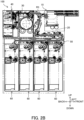
FIG. 2B is a left side view illustrating the internal structure of the bank bill processing machine for explaining second deposit processing in the one embodiment; -
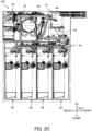
FIG. 2C is a left side view illustrating the internal structure of the bank bill processing machine for explaining withdrawal processing in the one embodiment; -
FIG. 3 is a left side view illustrating an internal structure of a bank bill deposit/withdrawal unit in one embodiment; -
FIG. 4A is a left side view (part 1) illustrating an internal structure of a bank bill deposit/withdrawal unit for explaining an operation at the time of deposition in one embodiment; -
FIG. 4B is a left side view (part 2) illustrating the internal structure of the bank bill deposit/withdrawal unit for explaining the operation at the time of deposition in the one embodiment; -
FIG. 4C is a left side view (part 3) illustrating the internal structure of the bank bill deposit/withdrawal unit for explaining the operation at the time of deposition in the one embodiment; -
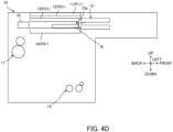
FIG. 4D is a left side view (part 4) illustrating the internal structure of the bank bill deposit/withdrawal unit for explaining the operation at the time of deposition in the one embodiment; -
FIG. 4E is a left side view (part 5) illustrating the internal structure of the bank bill deposit/withdrawal unit for explaining the operation at the time of deposition in the one embodiment; -
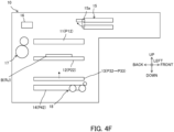
FIG. 4F is a left side view (part 6) illustrating the internal structure of the bank bill deposit/withdrawal unit for explaining the operation at the time of deposition in the one embodiment; -
FIG. 4G is a left side view (part 7) illustrating the internal structure of the bank bill deposit/withdrawal unit for explaining the operation at the time of deposition in the one embodiment; -
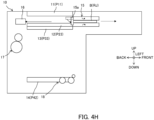
FIG. 4H is a left side view (part 8) illustrating the internal structure of the bank bill deposit/withdrawal unit for explaining the operation at the time of deposition in the one embodiment; -
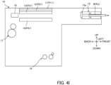
FIG. 4I is a left side view (part 9) illustrating the internal structure of the bank bill deposit/withdrawal unit for explaining the operation at the time of deposition in the one embodiment; -
FIG. 5A is a left side view (part 1) illustrating the internal structure of the bank bill deposit/withdrawal unit for explaining an operation at the time of withdrawal in one embodiment; -
FIG. 5B is a left side view (part 2) illustrating the internal structure of the bank bill deposit/withdrawal unit for explaining the operation at the time of withdrawal in the one embodiment; -
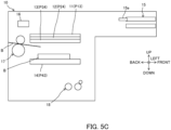
FIG. 5C is a left side view (part 3) illustrating the internal structure of the bank bill deposit/withdrawal unit for explaining the operation at the time of withdrawal in the one embodiment; -
FIG. 5D is a left side view (part 4) illustrating the internal structure of the bank bill deposit/withdrawal unit for explaining the operation at the time of withdrawal in the one embodiment; -
FIG. 5E is a left side view (part 5) illustrating the internal structure of the bank bill deposit/withdrawal unit for explaining the operation at the time of withdrawal in the one embodiment; -
FIG. 5F is a left side view (part 6) illustrating the internal structure of the bank bill deposit/withdrawal unit for explaining the operation at the time of withdrawal in the one embodiment; -
FIG. 5G is a left side view (part 7) illustrating the internal structure of the bank bill deposit/withdrawal unit for explaining the operation at the time of withdrawal in the one embodiment; -
FIG. 6 is a perspective view illustrating a roof, a pusher plate, a pusher, and the like in one embodiment; -
FIG. 7 is a perspective view illustrating a pressing portion, a tension spring, and the like in one embodiment; -
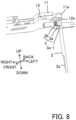
FIG. 8 is a perspective view illustrating the pressing portion and the like in one embodiment; -
FIG. 9 is a perspective view illustrating the pressing portion and the like in one embodiment; -
FIG. 10 is a perspective view illustrating two rails and the like in one embodiment; -
FIG. 11 is a cross-sectional view illustrating a roof, the pusher plate, the pusher, and the like in one embodiment; -
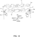
FIG. 12 is a perspective view illustrating the roof, the pusher plate, and the like in one embodiment; and -
FIG. 13 is a perspective view illustrating the roof, the pusher plate, and the like in one embodiment. - Hereinafter, a paper sheet handling apparatus according to an embodiment of the present invention will be described with reference to the drawings using a bank
bill processing machine 100 as an example. -
FIG. 1 is a left side view illustrating an internal structure of the bankbill processing machine 100. - Note that the up-down, front-back, and left-right directions illustrated in
FIG. 1 andFIGS. 2A to 13 to be described later are merely an example of a case where a customer side of the bankbill processing machine 100 is the front direction, but for example, the up-down direction is a vertical direction, and the front-back direction and the left-right direction are horizontal directions. - The bank
bill processing machine 100 illustrated inFIG. 1 is, for example, an ATM, a bill recycle unit (BRU), a cash dispenser (CD), a teller cash recycler (TCR), or the like, and includes a bank bill deposit/withdrawal unit 10, adiscrimination unit 20, aprimary holding unit 30, arejection unit 40, an intermediate conveyingunit 50, and a plurality ofstorage cassettes 60. Note that the bankbill processing machine 100 is an example of a paper sheet handling apparatus, but the paper sheet handling apparatus may be any apparatus as long as it conveys or performs some processing on a paper sheet including a bank bill B as an example, and thus the paper sheet handling apparatus can be regarded as, for example, only the bank bill deposit/withdrawal unit 10. - Although the bank bill deposit/
withdrawal unit 10 will be described in detail later, the bank bill deposit/withdrawal unit 10 is provided at the upper portion of the front end of aguide mechanism 1, and is where the bank bill B to be deposited is inserted and the bank bill B to be withdrawn is ejected. - The
discrimination unit 20 is arranged below the bank bill deposit/withdrawal unit 10 and determines authenticity, contamination, a folded corner, and the like of the bank bill B conveyed from the bank bill deposit/withdrawal unit 10. - The
primary holding unit 30 temporarily stores the bank bill B and the like that are conveyed from the bank bill deposit/withdrawal unit 10 to thediscrimination unit 20 and determined to be normal at thediscrimination unit 20. - The
rejection unit 40 stores an unreturned bank bill B among the bank bills B determined to be abnormal at thediscrimination unit 20. - The intermediate conveying
unit 50 conveys the bank bill B in the front-back direction between thediscrimination unit 20 and the plurality ofstorage cassettes 60. - The plurality of
storage cassettes 60 store, for example, the bank bills B of different denominations. The storage cassettes 60 can eject the stored bank bills B. The bank bills B stored in thestorage cassettes 60 are thus used for withdrawal. -
FIG. 2A to 2C are left side views illustrating an internal structure of the bankbill processing machine 100 for explaining first deposit processing, second deposit processing, and withdrawal processing. - First, as illustrated in a conveyance route R1 indicated by the thick solid arrow in
FIG. 2A , the bank bill B inserted into the bank bill deposit/withdrawal unit 10 is conveyed to thediscrimination unit 20. Then, the bank bill B determined to be normal at thediscrimination unit 20 is conveyed to theprimary holding unit 30. - On the other hand, as illustrated in a conveyance route R2 indicated by the thick dotted arrow in
FIG. 2A , the bank bill B determined to be abnormal at the discrimination unit 20 (such as a bogus bank bill) is returned to the bank bill deposit/withdrawal unit 10. - As illustrated in a conveyance route R3 indicated by the thick solid arrow in
FIG. 2B , the bank bill B temporarily stored in theprimary holding unit 30 is conveyed through thediscrimination unit 20 and the intermediate conveyingunit 50 and conveyed to eachstorage cassette 60. - As illustrated in a conveyance route R4 indicated by the thick solid arrow in
FIG. 2C , at the time of withdrawal, the bank bill B stored in eachstorage cassette 60 is ejected to the bank bill deposit/withdrawal unit 10 by the intermediate conveyingunit 50 and thediscrimination unit 20. In addition, as illustrated in a conveyance route R5 indicated by the thick dotted arrow inFIG. 2C , the bank bill B determined to be abnormal by thediscrimination unit 20 among the bank bills B stored in eachstorage cassette 60 is conveyed to theprimary holding unit 30 or therejection unit 40. -
FIG. 3 is a left side view illustrating the internal structure of the bank bill deposit/withdrawal unit 10. - As illustrated in
FIG. 3 , the bank bill deposit/withdrawal unit 10 includes a roof 11 (an example of a first partition member), a pusher plate 12 (an example of a second partition member), a pusher 13 (an example of a third partition member), astage 14, ashuttle 15, a push-inwall 16, a receivingunit 17, and a sendingunit 18. As will be described later, as illustrated inFIGS. 6 to 13 , the bank bill deposit/withdrawal unit 10 further includes twoguides 2, twopressing portions 3, amovable member 4, atiming belt 5, atension spring 6, and two rails 7 (seeFIG. 10 ). Note that, in the present embodiment, the plate-shaped roof 11 (first partition member), the pusher plate 12 (second partition member), and the pusher 13 (third partition member) will be described as an example of the plurality of partition members, but the partition member is not limited to a plate-shaped member, and may be, for example, a member having a roller, a belt, or the like and capable of conveying the bank bill B. - The
roof 11 is arranged so as to be capable of ascending and descending. - The
pusher plate 12 is arranged below theroof 11. Thepusher plate 12 is arranged so as to be capable of ascending and descending, and receives the bank bill B to be returned from the receivingunit 17 among the bank bills B sent from thestage 14 by the sendingunit 18. - The
pusher 13 is arranged below thepusher plate 12. Thepusher 13 is arranged so as to be capable of ascending and descending, and can press the bank bill B on thestage 14 from above. Note that, as illustrated inFIG. 11 to be described later, a plurality ofentry prevention members 13a that prevent the bank bill B from entering from below thepusher 13 are arranged on thepusher 13 with a space therebetween in the left-right direction so as to hang downward. - The
stage 14 is arranged so as to be capable of ascending and descending, and as illustrated inFIG. 3 , the bank bills B to be withdrawn or the bank bills B to be deposited are stacked on thestage 14. Note that thestage 14 ascends and descends due to driving of a drive unit (for example, a motor) different from a drive unit that raises and lowers thepusher 13. - The
shuttle 15 has, for example, a pair of upper and lower conveying belts capable of sandwiching the bank bill B, and moves in the front-back direction between a front position at the time of the deposit and withdrawal of the bank bill B (see the solid line inFIG. 3 ) and a back position at which the bank bill B is received and passed from and to the stage 14 (see the dotted line inFIG. 3 ). Astopper 15a is provided at the back end of theshuttle 15 to prevent the bank bill B from falling backward from theshuttle 15. Thestopper 15a rotates to a position where a space between the back ends of the pair of upper and lower conveying belts of theshuttle 15 is opened (see the solid line inFIG. 3 ) and a position where the space is closed (see the dotted line inFIG. 3 ). - The push-in
wall 16 is arranged to be movable in the front-back direction, and pushes the bank bill B on thestage 14 forward toward theshuttle 15 at the time of withdrawal (moves from the position of the solid line to the position of the dotted line inFIG. 3 ). - The receiving
unit 17 has, for example, an impeller and a roller. The receivingunit 17 receives the bank bill B to be withdrawn toward thestage 14 and receives the bank bill B to be returned toward thepusher plate 12. - The sending
unit 18 has, for example, a roller, a separator roller, or the like. The sendingunit 18 sends the deposited bank bill B toward thediscrimination unit 20 from thestage 14 that has descended below the position illustrated inFIG. 3 (see the dotted arrow inFIG. 3 ). - Here, before describing a configuration for raising and lowering the
roof 11, thepusher plate 12, and the pusher 13 (seeFIGS. 6 to 13 ), the outline of an operation at the time of deposit (FIGS. 4A to 4I ) and an operation at the time of withdrawal (FIGS. 5A to 5G ) of the bank bill deposit/withdrawal unit 10 will be described. -
FIGS. 4A to 4I are left side views illustrating the internal structure of the bank bill deposit/withdrawal unit 10 for explaining the operation at the time of deposition. - First, as illustrated in
FIG. 4A , the bank bill B is inserted between the pair of upper and lower conveying belts of theshuttle 15. At this time, theroof 11, thepusher plate 12, thepusher 13, and thestage 14 are at initial positions P11, P21, P31, and P41, respectively. Note that theroof 11, thepusher plate 12, and thepusher 13 are in close contact with each other at these initial positions, but thestage 14 is positioned below thepusher 13 with a space therebetween to form the storage space for the bank bill B. - Next, as illustrated in
FIG. 4B , theshuttle 15 moves backward toward thestage 14 while sandwiching the bank bill B. After theshuttle 15 moves backward, the pair of conveying belts of theshuttle 15 conveys the bank bill B onto thestage 14. - Next, as illustrated in
FIG. 4C , theshuttle 15 moves slightly forward once, and thestopper 15a rotates to the position where the space between the back ends of the pair of upper and lower conveying belts is closed. - Next, as illustrated in
FIG. 4D , when theshuttle 15 moves backward again, thestopper 15a pushes the bank bill B on thestage 14 backward. - Next, as illustrated in
FIG. 4E , theroof 11 and thepusher plate 12 descends to lower limit positions P12 and P22 spaced apart from each other, and thepusher 13 descends to a pressing position P32 where thepusher 13 presses the bank bill B on thestage 14 that has descended to a sending position P42 from above. - Then, the sending
unit 18 sends the bank bill B on thestage 14 toward the discrimination unit 20 (see the dotted arrow inFIG. 4E ). - A rejected bank bill B (RJ) determined to be abnormal by the
discrimination unit 20 among the bank bills B sent by the sendingunit 18 is returned to the bank bill deposit/withdrawal unit 10 as illustrated in the conveyance route R2 indicated by the bold dotted arrow inFIG. 2A described above, and received onto thepusher plate 12 from the receivingunit 17. - Next, as illustrated in
FIG. 4F , first, thepusher 13 ascends toward a rejected bank bill ejection position P33, and thestopper 15a rotates to the position where the space between the back ends of the pair of upper and lower conveying belts is opened. - Next, as illustrated in
FIG. 4G , when theroof 11 and thepusher plate 12 also ascend, theroof 11 reaches the initial position P11 and thepusher plate 12 and thepusher 13 reach the rejected bank bill ejection positions P23 and P33, and then the push-inwall 16 pushes the rejected bank bill B (RJ) on thestage 14 forward toward theshuttle 15. - Next, as illustrated in
FIG. 4H , the push-inwall 16 returns backward, and thestopper 15a rotates to the position where the space between the back ends of the pair of upper and lower conveying belts is closed. - Next, as illustrated in
FIG. 4I , theshuttle 15 moves forward, and the pair of upper and lower conveying belts ejects the rejected bank bill B (RJ) forward of the bank bill deposit/withdrawal unit 10. -
FIGS. 5A to 5G are left side views illustrating the internal structure of the bank bill deposit/withdrawal unit 10 for explaining the operation at the time of withdrawal. - First, as illustrated in
FIG. 5A , as in the start of the deposition operation illustrated inFIG. 4A , theroof 11, thepusher plate 12, thepusher 13, and thestage 14 are at the initial positions P11, P21, P31, and P41, respectively. - Next, as illustrated in
FIG. 5B , theroof 11, thepusher plate 12, and thepusher 13 descend integrally to withdrawal positions P13, P24, and P34. Thestage 14 also descends to a withdrawal position P43. Note that the withdrawal position P43 of thestage 14 may be detected by an upper end detection sensor of the bank bill B (not illustrated). - Next, as illustrated in
FIG. 5C , the bank bill B withdrawn from each storage cassette 60 (see the conveyance route R4 indicated by the bold solid arrow inFIG. 2C ) is received onto thestage 14 by the receivingunit 17. - Next, as illustrated in
FIG. 5D , theroof 11, thepusher plate 12, thepusher 13, and thestage 14 ascend to the initial positions P11, P21, P31, and P41, and theshuttle 15 moves backward to receive the bank bill B. - Next, as illustrated in
FIG. 5E , the push-inwall 16 pushes the bank bill B on thestage 14 forward toward theshuttle 15. - Next, as illustrated in
FIG. 5F , the push-inwall 16 returns backward, and thestopper 15a rotates to the position where the space between the back ends of the pair of upper and lower conveying belts is closed. - Next, as illustrated in
FIG. 5G , theshuttle 15 moves forward, and the pair of upper and lower conveying belts ejects the bank bill B forward of the bank bill deposit/withdrawal unit 10. - Here, the configuration for raising and lowering the
roof 11, thepusher plate 12, and thepusher 13 will be described with reference toFIGS. 6 to 13 . - As illustrated in
FIG. 6 , the twoguides 2 are fixed to the left back portion and the right front portion of theroof 11 at the upper end, and extend downward through thepusher plate 12. Theguides 2 are, for example, rod-like (cylindrical) shafts, but may be in a quadrangular prism shape, and the shape is not particularly limited. Recessedportions 2a are formed on the right side of theguide 2 on the left back portion (seeFIG. 8 ) and the left side of theguide 2 on the right front portion (seeFIG. 6 ). The recessedportion 2a, when facing apressing portion 3 to be described later, acts to cancel the frictional force generated by thepressing portion 3 pressing theguide 2, and is provided over a predetermined range in the up-down direction. Note that the recessedportion 2a only needs to be a recessed (concave) portion, and thus may be a hole, a notch, or the like penetrating theguide 2. - As illustrated in
FIG. 12 , the twopressing portions 3 are fixed to the left back portion and the right front portion of thepusher plate 12. Thepressing portion 3 has apin 3a extending in the left-right direction and having a large diameter at a contact portion with theguide 2, and acompression spring 3b that biases thepin 3a toward theguide 2. As illustrated inFIGS. 7 and8 , agroove 3a-1 extending in the up-down direction for accommodating a part of theguide 2 is preferably formed in the contact portion of thepin 3a with theguide 2. Thus, the rotation of thepin 3a is suppressed. Note that thecompression spring 3b may bias thepin 3a toward theguide 2 using a biasing force that enables thepusher plate 12 to ascend and descend integrally with theroof 11 due to a frictional force generated by thepin 3a pressing theguide 2. - As illustrated in
FIGS. 6 and7 , themovable member 4 is fixed to thepusher 13 and ascends and descends due to the rotation of the endless belt-shapedtiming belt 5. This raises and lowers thepusher 13. - The
tension spring 6 is hooked and fixed to themovable member 4 at the lower end, and is hooked and fixed to thepusher plate 12 at the upper end. Due to this, when themovable member 4 descends, thetension spring 6 pulls thepusher plate 12 downward and lowers thepusher plate 12. - As illustrated in
FIG. 10 , the tworails 7 are arranged side by side in the front-back direction on the left side of theroof 11, thepusher plate 12, and thepusher 13, and extend in the up-down direction. Each of the tworails 7 has a U-shape facing rightward in plan view. - The hollow portion in the
rail 7 has a depth in the left-right direction that is deep at the upper portion of therail 7 and shallow at the lower portion of therail 7, and the step functions as afirst stopper 7a. In addition, the hollow portion in therail 7 is not provided up to the lower end of therail 7 and there is no hollow portion at the lower portion of therail 7, and thus the step functions as asecond stopper 7b. In this manner, thefirst stopper 7a and thesecond stopper 7b are provided on thecommon rail 7. - As illustrated in
FIG. 11 , thefirst stoppers 7a of the tworails 7 come into contact with twoprotrusions 11a protruding leftward from theroof 11 at the lower limit position of theroof 11. As a result, theroof 11 no longer descends after theprotrusion 11a and thefirst stopper 7a come into contact with each other. Note that the lower limit position of theroof 11 is, for example, the lower limit position P12 illustrated inFIG. 4E . - As illustrated in
FIG. 11 , thesecond stoppers 7b of the tworails 7 come into contact with twoprotrusions 12a protruding leftward from thepusher plate 12 at the lower limit position of thepusher plate 12. As a result, thepusher plate 12 no longer descends after theprotrusion 12a and thesecond stopper 7b come into contact with each other. Note that the lower limit position of thepusher plate 12 is, for example, the lower limit position P22 illustrated inFIG. 4E . - Note that the
protrusion 12a of thepusher plate 12 has a smaller protruding amount in the left direction than theprotrusion 11a of theroof 11, and the end of theprotrusion 12a is positioned on the right side of the end of theprotrusion 11a. Due to this, theprotrusion 12a of thepusher plate 12 does not come into contact with thefirst stopper 7a. - With the above-described configuration, the
roof 11, thepusher plate 12, and thepusher 13 ascend and descend as follows. First, as illustrated inFIGS. 6 and7 , theroof 11, thepusher plate 12, and thepusher 13 that are in close contact with each other at the initial positions (the initial positions P11, P21, and P31 inFIGS. 4A and5A ), thepusher 13 first descends due to the rotation of the timing belt 5 (descent of the movable member 4). - As the
pusher 13 descends, thetension spring 6 fixed to thepusher 13 via themovable member 4 pulls thepusher plate 12 downward and lowers thepusher plate 12. Then, as thepusher plate 12 descends, theroof 11 descends integrally due to the frictional force generated by thepressing portion 3 fixed to thepusher plate 12 pressing theguide 2. In this manner, first, theroof 11, thepusher plate 12, and thepusher 13 descend integrally (seeFIG. 5B ). - Thereafter, the two
protrusions 11a of theroof 11 come into contact with thefirst stoppers 7a (seeFIG. 11 ) of the tworails 7, and then thepusher plate 12 and thepusher 13 descend independently of theroof 11 against the frictional force generated by thepressing portion 3 pressing theguide 2. As illustrated inFIG. 9 , when thepusher plate 12 descends to a position where thepressing portion 3 faces the recessedportion 2a of theguide 2, the frictional force is canceled. - Thereafter, the two
protrusions 12a of thepusher plate 12 come into contact with thesecond stoppers 7b (seeFIG. 11 ) of the tworails 7, and, as illustrated inFIGS. 10 and11 , thepusher 13 descends independently of thepusher plate 12 against the restoring force of thetension spring 6. - When the
roof 11, thepusher plate 12, and thepusher 13 ascend from the descending positions, thepusher 13 first ascends due to the rotation of the timing belt 5 (ascent of the movable member 4). - Thereafter, when the
pusher 13 lifts thepusher plate 12 at the lower limit position, thepusher plate 12 also starts to ascend, thepusher plate 12 ascends to a position where thepressing portion 3 fixed to thepusher plate 12 no longer faces the recessedportion 2a of theguide 2 as illustrated inFIGS. 12 and13 , and then theroof 11 ascends integrally with thepusher plate 12 and thepusher 13 due to the above-described frictional force. Then, theroof 11, thepusher plate 12, and thepusher 13 return to the initial positions as illustrated inFIGS. 6 and7 . Note that the upper limit position of theroof 11 is preferably determined by, for example, being in contact with the inner upper surface of the bank bill deposit/withdrawal unit 10. - Here, although the
pusher 13 is driven by the timing belt 5 (drive unit) in the bank bill deposit/withdrawal unit 10 (bank bill processing machine 100), theroof 11 and thepusher plate 12 may be raised and lowered by driving thepusher plate 12. In addition, although theroof 11 has been described as an example of the first partition member, and thepusher plate 12 has been described as an example of the second partition member, the first partition member may be thepusher plate 12, the second partition member may be thepusher 13, or the like, and each partition member may be any member. - In the present embodiment described above, the bank
bill processing machine 100, which is an example of the paper sheet handling apparatus, includes: a plurality of partition members that have the roof 11 (an example of the first partition member) and the pusher plate 12 (an example of the second partition member) arranged below theroof 11 and are capable of ascending and descending to form the storage space for the bank bill B (an example of the paper sheet); theguide 2 that is fixed to theroof 11 and extends downward; thefirst stopper 7a (seeFIG. 11 ) that is in contact with theroof 11 at the lower limit position P12 (seeFIG. 4E ) of theroof 11; and thepressing portion 3 that is fixed to thepusher plate 12 and raises and lowers theroof 11 integrally with thepusher plate 12 using the frictional force generated by pressing theguide 2. Theguide 2 has the recessedportion 2a that cancels the frictional force, and thepusher plate 12 descends integrally with theroof 11, and, after theroof 11 comes into contact with thefirst stopper 7a, descends independently of theroof 11 against the frictional force to the position where thepressing portion 3 faces the recessedportion 2a. In addition, thepusher plate 12 ascends integrally with theroof 11 due to the frictional force when thepusher plate 12 ascends to the position where thepressing portion 3 no longer faces the recessedportion 2a from the position where thepressing portion 3 faces the recessedportion 2a. - This enables the
pusher plate 12 to be raised and lowered integrally with theroof 11 or to be raised and lowered independently of theroof 11. Thus, the arrangement of the drive unit (drive source) that individually raises and lowers theroof 11 can be omitted. Therefore, according to the present embodiment, the plurality of partition members (theroof 11, thepusher plate 12, and the like) can be raised and lowered to the plurality of predetermined positions with the simple configuration. - In addition, in the present embodiment, the plurality of partition members further have the pusher 13 (an example of the third partition member) arranged below the pusher plate 12 (an example of the second partition member). The bank
bill processing machine 100 further includes thesecond stopper 7b (seeFIG. 11 ) that comes into contact with thepusher plate 12 at the lower limit position P22 (seeFIG. 4E ) of thepusher plate 12, and thetension spring 6 that is fixed to thepusher 13 and pulls thepusher plate 12 downward. Thepusher 13 is arranged so as to be capable of lifting thepusher plate 12 at the time of ascent, and descends independently of thepusher plate 12 against the restoring force of thetension spring 6 after thepusher plate 12 pulled downward by thetension spring 6 comes into contact with thesecond stopper 7b at the time of descent. - This enables the
pusher 13 to be raised and lowered integrally with thepusher plate 12 or raised and lowered independently of thepusher plate 12. Thus, not only the arrangement of the drive unit (drive source) that individually raises and lowers theroof 11 but also the arrangement of the drive unit that individually raises and lowers thepusher plate 12 can be omitted. Therefore, the plurality of partition members (theroof 11, thepusher plate 12, and the pusher 13) can be raised and lowered to the plurality of predetermined positions with an even simpler configuration. - In addition, in the present embodiment, the bank
bill processing machine 100 further includes therail 7 extending in the up-down direction, and the above-describedfirst stopper 7a and thesecond stopper 7b are provided on the above-describedcommon rail 7. - This enables the plurality of partition members (the
roof 11, thepusher plate 12, and the pusher 13) to be raised and lowered to the plurality of predetermined positions with an even simpler configuration as compared with a case where the member that determines the lower limit position of the roof 11 (first stopper 7a) and the member that determines the lower limit position of the pusher plate 12 (second stopper 7b) are arranged on different members. - Note that the present invention is not limited to an original configuration of the above-described embodiment, and can be embodied by modifying components. For example, various inventions can be formed by appropriately combining a plurality of components disclosed in the present embodiment. As described above, various modifications and applications of the invention can be made without departing from the gist of the invention.
Claims (3)
- A paper sheet handling apparatus comprising:a plurality of partition members having a first partition member and a second partition member arranged below the first partition member, the plurality of partition members being capable of ascending and descending to form a storage space for a paper sheet;a guide fixed to the first partition member and extending downward;a first stopper that is in contact with the first partition member at a lower limit position of the first partition member; anda pressing portion that is fixed to the second partition member and raises and lowers the first partition member integrally with the second partition member using a frictional force generated by pressing the guide, whereinthe guide has a recessed portion that cancels the frictional force,the second partition member descends integrally with the first partition member, and after the first partition member comes into contact with the first stopper, the second partition member descends independently of the first partition member against the frictional force to a position where the pressing portion faces the recessed portion, andthe second partition member, when ascending from the position where the pressing portion faces the recessed portion to a position where the pressing portion no longer faces the recessed portion, ascends integrally with the first partition member due to the frictional force.
- The paper sheet handling apparatus according to claim 1, whereinthe plurality of partition members further have a third partition member arranged below the second partition member,the paper sheet handling apparatus further comprises:a second stopper that comes into contact with the second partition member at a lower limit position of the second partition member; anda tension spring that is fixed to the third partition member and pulls the second partition member downward, andthe third partition member is arranged so as to be capable of lifting the second partition member at the time of ascent, and at the time of descent, descends independently of the second partition member against a restoring force of the tension spring after the second partition member pulled downward by the tension spring comes into contact with the second stopper.
- The paper sheet handling apparatus according to claim 2, further comprising a rail extending in an up-down direction, wherein
the first stopper and the second stopper are provided on the common rail.
Applications Claiming Priority (1)
| Application Number | Priority Date | Filing Date | Title |
|---|---|---|---|
| PCT/JP2021/047616 WO2023119495A1 (en) | 2021-12-22 | 2021-12-22 | Paper sheet handling device |
Publications (2)
| Publication Number | Publication Date |
|---|---|
| EP4456023A1 true EP4456023A1 (en) | 2024-10-30 |
| EP4456023A4 EP4456023A4 (en) | 2025-02-19 |
Family
ID=86901691
Family Applications (1)
| Application Number | Title | Priority Date | Filing Date |
|---|---|---|---|
| EP21968932.0A Pending EP4456023A4 (en) | 2021-12-22 | 2021-12-22 | PAPER SHEET HANDLING DEVICE |
Country Status (5)
| Country | Link |
|---|---|
| US (1) | US12497262B2 (en) |
| EP (1) | EP4456023A4 (en) |
| JP (1) | JP7587062B2 (en) |
| CN (1) | CN118489129A (en) |
| WO (1) | WO2023119495A1 (en) |
Family Cites Families (9)
| Publication number | Priority date | Publication date | Assignee | Title |
|---|---|---|---|---|
| JPH07220139A (en) | 1994-01-31 | 1995-08-18 | Toyo Commun Equip Co Ltd | Paper delivery device |
| JP4320281B2 (en) * | 2004-06-11 | 2009-08-26 | 日立オムロンターミナルソリューションズ株式会社 | Banknote handling equipment |
| JP4265511B2 (en) | 2004-09-22 | 2009-05-20 | 富士電機リテイルシステムズ株式会社 | Banknote storage, banknote processing apparatus and money processing apparatus |
| US8695960B2 (en) * | 2011-12-20 | 2014-04-15 | Xerox Corporation | Automatic media loading and unloading system for producing dimensional documents |
| JP6204824B2 (en) * | 2013-12-26 | 2017-09-27 | 株式会社Isowa | Cardboard sheet feeding device |
| JP2016069169A (en) * | 2014-09-30 | 2016-05-09 | 株式会社東芝 | Paper sheet feeding device |
| JP2018032341A (en) | 2016-08-26 | 2018-03-01 | 沖電気工業株式会社 | Medium delivery device |
| JP6776134B2 (en) | 2017-01-16 | 2020-10-28 | 日立オムロンターミナルソリューションズ株式会社 | Banknote processing device |
| CN207601909U (en) | 2017-11-22 | 2018-07-10 | 深圳怡化电脑股份有限公司 | A kind of medium storage device and medium authentication terminal |
-
2021
- 2021-12-22 WO PCT/JP2021/047616 patent/WO2023119495A1/en not_active Ceased
- 2021-12-22 EP EP21968932.0A patent/EP4456023A4/en active Pending
- 2021-12-22 JP JP2023568887A patent/JP7587062B2/en active Active
- 2021-12-22 CN CN202180104924.4A patent/CN118489129A/en active Pending
-
2024
- 2024-05-28 US US18/675,935 patent/US12497262B2/en active Active
Also Published As
| Publication number | Publication date |
|---|---|
| JPWO2023119495A1 (en) | 2023-06-29 |
| EP4456023A4 (en) | 2025-02-19 |
| US20240312281A1 (en) | 2024-09-19 |
| JP7587062B2 (en) | 2024-11-19 |
| US12497262B2 (en) | 2025-12-16 |
| WO2023119495A1 (en) | 2023-06-29 |
| CN118489129A (en) | 2024-08-13 |
Similar Documents
| Publication | Publication Date | Title |
|---|---|---|
| KR101075927B1 (en) | Paper sheet receiving apparatus | |
| EP2481029B1 (en) | Document storage assembly | |
| KR101085379B1 (en) | Banknote accumulator | |
| KR102460933B1 (en) | Leaf loading device, and load adjustment method | |
| US12497262B2 (en) | Paper sheet handling apparatus | |
| JPH0544347Y2 (en) | ||
| CN105122321B (en) | Media storage device and medium transaction device | |
| KR101275926B1 (en) | Note-bundle conveying apparatus and paper-note handling device | |
| RU2753960C1 (en) | Apparatus for processing paper sheets | |
| EP4109427A1 (en) | Paper sheet handling device | |
| JP6060806B2 (en) | Medium storage apparatus and medium transaction apparatus | |
| CN104937643B (en) | Paper storage device, paper processing device, and paper conveying device | |
| JP2577779B2 (en) | Paper sheet classification method | |
| JP7653575B2 (en) | Paper sheet storage device | |
| JPH0737165Y2 (en) | Paper storage section of paper storage / feeding device | |
| JP2673723B2 (en) | Paper sheet deposition equipment | |
| JP2018032341A (en) | Medium delivery device | |
| JP3486109B2 (en) | Media storage and feeding device | |
| JP2000113279A (en) | Paper storage device | |
| JP5211323B2 (en) | Banknote handling apparatus and banknote handling apparatus | |
| JP3382813B2 (en) | Media storage | |
| JP3290075B2 (en) | Card cassette and card issuing device for card issuing device | |
| JPS6128578B2 (en) | ||
| JPH0797146A (en) | Accumulated storage device for paper sheet | |
| JP2021012454A (en) | Bill processing device |
Legal Events
| Date | Code | Title | Description |
|---|---|---|---|
| STAA | Information on the status of an ep patent application or granted ep patent |
Free format text: STATUS: THE INTERNATIONAL PUBLICATION HAS BEEN MADE |
|
| PUAI | Public reference made under article 153(3) epc to a published international application that has entered the european phase |
Free format text: ORIGINAL CODE: 0009012 |
|
| STAA | Information on the status of an ep patent application or granted ep patent |
Free format text: STATUS: REQUEST FOR EXAMINATION WAS MADE |
|
| 17P | Request for examination filed |
Effective date: 20240521 |
|
| AK | Designated contracting states |
Kind code of ref document: A1 Designated state(s): AL AT BE BG CH CY CZ DE DK EE ES FI FR GB GR HR HU IE IS IT LI LT LU LV MC MK MT NL NO PL PT RO RS SE SI SK SM TR |
|
| REG | Reference to a national code |
Ref country code: DE Ref legal event code: R079 Free format text: PREVIOUS MAIN CLASS: G07D0011130000 Ipc: B65H0031300000 |
|
| A4 | Supplementary search report drawn up and despatched |
Effective date: 20250121 |
|
| RIC1 | Information provided on ipc code assigned before grant |
Ipc: G07D 11/13 20190101ALI20250115BHEP Ipc: B65H 1/06 20060101ALI20250115BHEP Ipc: B65H 31/24 20060101ALI20250115BHEP Ipc: B65H 83/02 20060101ALI20250115BHEP Ipc: B65H 31/30 20060101AFI20250115BHEP |
|
| DAV | Request for validation of the european patent (deleted) | ||
| DAX | Request for extension of the european patent (deleted) |