EP4455986A1 - Datenverarbeitungsverfahren und -vorrichtung sowie vorrichtung und speichermedium - Google Patents
Datenverarbeitungsverfahren und -vorrichtung sowie vorrichtung und speichermedium Download PDFInfo
- Publication number
- EP4455986A1 EP4455986A1 EP23858740.6A EP23858740A EP4455986A1 EP 4455986 A1 EP4455986 A1 EP 4455986A1 EP 23858740 A EP23858740 A EP 23858740A EP 4455986 A1 EP4455986 A1 EP 4455986A1
- Authority
- EP
- European Patent Office
- Prior art keywords
- image
- pixel
- image frame
- pixels
- mask
- Prior art date
- Legal status (The legal status is an assumption and is not a legal conclusion. Google has not performed a legal analysis and makes no representation as to the accuracy of the status listed.)
- Pending
Links
Images


Classifications
-
- G—PHYSICS
- G06—COMPUTING OR CALCULATING; COUNTING
- G06T—IMAGE DATA PROCESSING OR GENERATION, IN GENERAL
- G06T11/00—2D [Two Dimensional] image generation
- G06T11/40—Filling a planar surface by adding surface attributes, e.g. colour or texture
-
- G—PHYSICS
- G06—COMPUTING OR CALCULATING; COUNTING
- G06T—IMAGE DATA PROCESSING OR GENERATION, IN GENERAL
- G06T1/00—General purpose image data processing
- G06T1/20—Processor architectures; Processor configuration, e.g. pipelining
-
- G—PHYSICS
- G06—COMPUTING OR CALCULATING; COUNTING
- G06T—IMAGE DATA PROCESSING OR GENERATION, IN GENERAL
- G06T1/00—General purpose image data processing
- G06T1/60—Memory management
-
- G06T11/10—
-
- G—PHYSICS
- G06—COMPUTING OR CALCULATING; COUNTING
- G06T—IMAGE DATA PROCESSING OR GENERATION, IN GENERAL
- G06T15/00—3D [Three Dimensional] image rendering
- G06T15/005—General purpose rendering architectures
-
- G—PHYSICS
- G06—COMPUTING OR CALCULATING; COUNTING
- G06T—IMAGE DATA PROCESSING OR GENERATION, IN GENERAL
- G06T15/00—3D [Three Dimensional] image rendering
- G06T15/04—Texture mapping
-
- G—PHYSICS
- G06—COMPUTING OR CALCULATING; COUNTING
- G06T—IMAGE DATA PROCESSING OR GENERATION, IN GENERAL
- G06T15/00—3D [Three Dimensional] image rendering
- G06T15/10—Geometric effects
- G06T15/20—Perspective computation
- G06T15/205—Image-based rendering
-
- G—PHYSICS
- G06—COMPUTING OR CALCULATING; COUNTING
- G06T—IMAGE DATA PROCESSING OR GENERATION, IN GENERAL
- G06T3/00—Geometric image transformations in the plane of the image
- G06T3/18—Image warping, e.g. rearranging pixels individually
-
- G—PHYSICS
- G06—COMPUTING OR CALCULATING; COUNTING
- G06T—IMAGE DATA PROCESSING OR GENERATION, IN GENERAL
- G06T7/00—Image analysis
- G06T7/10—Segmentation; Edge detection
- G06T7/11—Region-based segmentation
-
- G—PHYSICS
- G06—COMPUTING OR CALCULATING; COUNTING
- G06T—IMAGE DATA PROCESSING OR GENERATION, IN GENERAL
- G06T7/00—Image analysis
- G06T7/90—Determination of colour characteristics
-
- H—ELECTRICITY
- H04—ELECTRIC COMMUNICATION TECHNIQUE
- H04N—PICTORIAL COMMUNICATION, e.g. TELEVISION
- H04N19/00—Methods or arrangements for coding, decoding, compressing or decompressing digital video signals
- H04N19/10—Methods or arrangements for coding, decoding, compressing or decompressing digital video signals using adaptive coding
- H04N19/102—Methods or arrangements for coding, decoding, compressing or decompressing digital video signals using adaptive coding characterised by the element, parameter or selection affected or controlled by the adaptive coding
- H04N19/132—Sampling, masking or truncation of coding units, e.g. adaptive resampling, frame skipping, frame interpolation or high-frequency transform coefficient masking
-
- H—ELECTRICITY
- H04—ELECTRIC COMMUNICATION TECHNIQUE
- H04N—PICTORIAL COMMUNICATION, e.g. TELEVISION
- H04N19/00—Methods or arrangements for coding, decoding, compressing or decompressing digital video signals
- H04N19/50—Methods or arrangements for coding, decoding, compressing or decompressing digital video signals using predictive coding
- H04N19/503—Methods or arrangements for coding, decoding, compressing or decompressing digital video signals using predictive coding involving temporal prediction
-
- H—ELECTRICITY
- H04—ELECTRIC COMMUNICATION TECHNIQUE
- H04N—PICTORIAL COMMUNICATION, e.g. TELEVISION
- H04N19/00—Methods or arrangements for coding, decoding, compressing or decompressing digital video signals
- H04N19/80—Details of filtering operations specially adapted for video compression, e.g. for pixel interpolation
-
- H—ELECTRICITY
- H04—ELECTRIC COMMUNICATION TECHNIQUE
- H04N—PICTORIAL COMMUNICATION, e.g. TELEVISION
- H04N19/00—Methods or arrangements for coding, decoding, compressing or decompressing digital video signals
- H04N19/85—Methods or arrangements for coding, decoding, compressing or decompressing digital video signals using pre-processing or post-processing specially adapted for video compression
- H04N19/86—Methods or arrangements for coding, decoding, compressing or decompressing digital video signals using pre-processing or post-processing specially adapted for video compression involving reduction of coding artifacts, e.g. of blockiness
-
- H—ELECTRICITY
- H04—ELECTRIC COMMUNICATION TECHNIQUE
- H04N—PICTORIAL COMMUNICATION, e.g. TELEVISION
- H04N7/00—Television systems
- H04N7/01—Conversion of standards, e.g. involving analogue television standards or digital television standards processed at pixel level
- H04N7/0127—Conversion of standards, e.g. involving analogue television standards or digital television standards processed at pixel level by changing the field or frame frequency of the incoming video signal, e.g. frame rate converter
-
- H—ELECTRICITY
- H04—ELECTRIC COMMUNICATION TECHNIQUE
- H04N—PICTORIAL COMMUNICATION, e.g. TELEVISION
- H04N7/00—Television systems
- H04N7/01—Conversion of standards, e.g. involving analogue television standards or digital television standards processed at pixel level
- H04N7/0135—Conversion of standards, e.g. involving analogue television standards or digital television standards processed at pixel level involving interpolation processes
- H04N7/0137—Conversion of standards, e.g. involving analogue television standards or digital television standards processed at pixel level involving interpolation processes dependent on presence/absence of motion, e.g. of motion zones
-
- H—ELECTRICITY
- H04—ELECTRIC COMMUNICATION TECHNIQUE
- H04N—PICTORIAL COMMUNICATION, e.g. TELEVISION
- H04N7/00—Television systems
- H04N7/01—Conversion of standards, e.g. involving analogue television standards or digital television standards processed at pixel level
- H04N7/0135—Conversion of standards, e.g. involving analogue television standards or digital television standards processed at pixel level involving interpolation processes
- H04N7/014—Conversion of standards, e.g. involving analogue television standards or digital television standards processed at pixel level involving interpolation processes involving the use of motion vectors
-
- G—PHYSICS
- G06—COMPUTING OR CALCULATING; COUNTING
- G06T—IMAGE DATA PROCESSING OR GENERATION, IN GENERAL
- G06T2207/00—Indexing scheme for image analysis or image enhancement
- G06T2207/10—Image acquisition modality
- G06T2207/10024—Color image
Definitions
- This application relates to the field of data processing technologies, and in particular, to a data processing method and apparatus, a device, and a storage medium.
- a frame prediction technology is mainly used for increasing a frame rate, reducing frame freezing during image rendering, and reducing game rendering power consumption.
- a texture compression technology is generally used.
- the texture compression technology can only process image texture data created offline, and needs to perform operations of image texture data reading and rendering target writing a plurality of times online, resulting in high power consumption and a problem of device heating.
- Embodiments of this application provide a data processing method and apparatus, a device, and a storage medium, to resolve problems of high power consumption and device heating during image rendering.
- a first aspect of this application provides a data processing method.
- the method can be performed by a graphics processing unit GPU in an electronic device.
- the GPU may further perform the following data processing method.
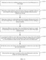
- the data processing method includes: The GPU obtains a first real image frame and a second real image frame; processes, when a frame interpolation condition is satisfied between the first real image frame and the second real image frame, the first real image frame to obtain a first image and a mask image of the first image, where the mask image is used for marking to-be-filled pixels and effective pixels in the first image; samples mask data of the mask image pixel by pixel to determine whether pixels in the first image are to-be-filled pixels during performing pixel filling on the first image; and reads, for any one of the to-be-filled pixels in the first image, color data of the first real image frame from an internal memory, and uses the color data to perform color filling on the to-be-filled pixel in the first image, to generate
- the first real image frame is processed to generate the first image having the to-be-filled pixels and the mask image corresponding to the first image.
- the mask data in the mask image is sampled to determine the to-be-filled pixels and the effective pixels in the first image, so that the effective pixels are not processed.
- the color data of the effective pixels in the first image is retained.
- the color data of the first real image frame is read from the internal memory, and the color data is used to perform the color filling on the to-be-filled pixel with missing pixel data in the first image, to obtain the predicted image frame used for display between the first real image frame and the second real image frame.
- the predicted image frame is generated for frame interpolation display to improve a display frame rate of an image.
- data filling is only performed on the to-be-filled pixels in the first image, and the effective pixels in the first image are retained.
- Intermediate data of a pixel filling algorithm is reused, to significantly reduce a quantity of memory accesses and data volume of a single memory access, effectively reduce power consumption of a device, and resolve a problem of device heating while ensuring integrity of a color of the predicted image frame.
- the frame interpolation condition includes that a moving distance between two consecutive real image frames is less than a distance threshold and there is no translucent object in a real image frame.
- the frame interpolation condition is set to enable the GPU to perform frame interpolation processing when the frame interpolation condition is satisfied, to ensure a quality of the generated predicted image frame, thereby improving a visual effect of an image.
- the method further includes: determining whether there is a translucent object in the first real image frame; calculating a first moving distance between the first real image frame and the second real image frame in response to that there is no translucent object in the first real image frame; determining whether the first moving distance is less than the distance threshold; determining, in response to that the first moving distance is less than the distance threshold, that the frame interpolation condition is satisfied between the first real image frame and the second real image frame; and determining, in response to that there is a translucent object in the first real image frame and/or the first moving distance is greater than or equal to the distance threshold, that the frame interpolation condition is not satisfied between the first real image frame and the second real image frame.
- an execution order of the two frame interpolation conditions is not limited and may be determined according to an actual scenario.
- the frame interpolation condition when there is no translucent object in the first real image frame and the first moving distance between the first real image frame and the second real image frame is less than the distance threshold, it is determined that the frame interpolation condition is satisfied between the first real image frame and the second real image frame. However, when there is a translucent object in the first real image frame and/or the first moving distance is greater than or equal to the distance threshold, it is determined that the frame interpolation condition is not satisfied between the first real image frame and the second real image frame. In this way, occurrence of a poor-quality predicted image frame can be effectively reduced or avoided, and an objective of ensuring frame interpolation quality when a frame rate is improved is achieved.
- the reading color data of the first real image frame from an internal memory, and using the color data to perform color filling on the to-be-filled pixel in the first image includes: determining at least one candidate reference pixel of the to-be-filled pixel in the first image; determining a target reference pixel from the at least one candidate reference pixel based on object categories to which candidate reference pixels respectively belong; determining, based on a relationship between the target reference pixel and the first real image frame, color data of the target reference pixel by reading the internal memory; and performing the color filling on the to-be-filled pixel based on the color data of the target reference pixel.
- the candidate reference pixel is determined first, and then the target reference pixel is determined based on the object categories to which the pixels belongs, and the color data of the target reference pixel is read from the internal memory, to implement the color filling on the to-be-filled pixel.
- the color data of the target reference pixel is read from the internal memory, to significantly reduce a quantity of memory accesses and data volume of a single memory access and effectively reduce power consumption of a device while ensuring integrity of a color of the predicted image frame.
- the determining a candidate reference pixel of the to-be-filled pixel in the first image includes: randomly moving to a first position in the first image with a position of the to-be-filled pixel as a starting point; determining, if a pixel at the first position is not a to-be-filled pixel, that the pixel at the first position is the candidate reference pixel of the to-be-filled pixel; and if the pixel at the first position is a to-be-filled pixel, continuing to randomly move in the first image with the first position as the starting point until moving to a second position that is not a to-be-filled pixel, and determining the second position as the candidate reference pixel of the to-be-filled pixel.
- the candidate reference pixel of the to-be-filled pixel may be determined through random movement search, to lay a foundation for subsequent determining of the target reference pixel.
- the performing the color filling on the to-be-filled pixel based on the color data of the target reference pixel includes: determining effective color data of the target reference pixel based on a weight corresponding to the target reference pixel and the color data of the target reference pixel; accumulating the effective color data into existing color data of the to-be-filled pixel until a quantity of color accumulations of the to-be-filled pixel is equal to a first threshold to obtain current color data of the to-be-filled pixel; dividing the current color data by the first threshold to obtain first color data of the to-be-filled pixel; and writing the first color data to a position of the to-be-filled pixel in the first image.
- a weight value based on the target reference pixel is defined based on a distance between the to-be-filled pixel and the target reference pixel. In this way, the effective color data of the target reference pixel may be accurately determined, and then actual color data to be filled into the to-be-filled pixel is obtained based on the quantity of color accumulations of the first threshold. This can improve a color quality of the to-be-filled pixel, to further ensure a filling effect.
- the processing the first real image frame to obtain a first image and a mask image of the first image includes: using, based on object categories to which pixels in the first real image frame respectively belong, a motion vector to perform an image warp operation twice on the first real image frame to generate the first image; and generating the mask image of the first image based on whether color data exists for the pixels in the first image.
- a pixel of a static object and a pixel of a dynamic object in the first real image frame are offset respectively, and the mask image of the first image is generated based on whether the pixels in the first image are covered after two offsets, in other words, whether there is the color data. In this way, the mask image that can be generated can accurately mark the to-be-filled pixels and the effective pixels in the first image.
- the processing the first real image frame to obtain a first image and a mask image of the first image includes: generating a stencil buffer of the first real image frame based on the object categories to which the pixels in the first real image frame respectively belong; querying the stencil buffer, and determining object categories to which pixels in a mask texture image respectively belong, where the mask texture image is an image of which initial values are all equal to a first value, and the first value is used for marking the to-be-filled pixels in the first image; and using, based on the object categories to which the pixels respectively belong, a motion vector to perform an image warp operation twice on both the first real image frame and the mask texture image to generate the first image and the mask image of the first image.
- the mask image is generated by displacing, based on the object categories to which the pixels in the first real image frame respectively belong, the mask texture image of which initial values are all equal to the first value.
- a displacement process of the mask image is the same as that of the first image, so that the mask image can accurately mark the to-be-filled pixels and the effective pixels in the first image.
- the using, based on the object categories to which the pixels respectively belong, a motion vector to perform an image warp operation twice on both the first real image frame and the mask texture image to generate the first image and the mask image of the first image includes:
- the first object category is a static object
- the second object category is a dynamic object
- the first object category is a dynamic object
- the second object category is a static object
- the sampling mask data of the mask image pixel by pixel to determine whether pixels in the first image are to-be-filled pixels includes: sampling mask data of pixels in the mask image pixel by pixel; determining, if the mask data of the sampled pixels is equal to the first value in the mask image, that a pixel at a corresponding position in the first image is a to-be-filled pixel; and determining, if the mask data of the sampled pixels is equal to a second value, that the pixel at the corresponding position in the first image is not a to-be-filled pixel.
- the mask data of the pixels in the mask image is sampled to determine, based on a value of the mask data, whether the pixel at the corresponding position in the first image is a to-be-filled pixel, to lay a foundation for subsequent targeted pixel filling.
- the mask image is a binary image, the first value is equal to 1, and the second value is equal to 0.
- the mask image is a single-channel 8-bit mask image.
- the mask image is a single-channel 8-bit mask image.
- 8-bit Mask data For the pixels that do not need to be filled in the first image, only a read operation needs to be performed on 8-bit Mask data once, instead of a read operation and a write operation on 32-bit image data once. This reduces data volume of a memory access.
- a second aspect of this application provides a data processing apparatus.
- the data processing apparatus may be implemented by a graphics processing unit GPU in an electronic device.
- the data processing apparatus includes:
- the frame interpolation condition includes that a moving distance between two consecutive real image frames is less than a distance threshold and there is no translucent object in a real image frame.
- the processing unit is further configured to perform the following operations: determining whether there is a translucent object in the first real image frame; calculating a first moving distance between the first real image frame and the second real image frame in response to that there is no translucent object in the first real image frame; determining whether the first moving distance is less than the distance threshold; determining, in response to that the first moving distance is less than the distance threshold, that the frame interpolation condition is satisfied between the first real image frame and the second real image frame; and determining, in response to that there is a translucent object in the first real image frame and/or the first moving distance is greater than or equal to the distance threshold, that the frame interpolation condition is not satisfied between the first real image frame and the second real image frame.
- the filling unit when the color data of the first real image frame is read from the internal memory, and the color data is used to perform the color filling on the to-be-filled pixel in the first image, the filling unit is specifically configured to: determine at least one candidate reference pixel of the to-be-filled pixel in the first image; determine a target reference pixel from the at least one candidate reference pixel based on object categories to which candidate reference pixels respectively belong; determine, based on a relationship between the target reference pixel and the first real image frame, color data of the target reference pixel by reading the internal memory; and perform the color filling on the to-be-filled pixel based on the color data of the target reference pixel.
- the filling unit is specifically configured to: randomly move to a first position in the first image with a position of the to-be-filled pixel as a starting point; determine, if a pixel at the first position is not a to-be-filled pixel, that the pixel at the first position is the candidate reference pixel of the to-be-filled pixel; and if the pixel at the first position is a to-be-filled pixel, continue to randomly move in the first image with the first position as the starting point until moving to a second position that is not a to-be-filled pixel, and determine the second position as the candidate reference pixel of the to-be-filled pixel.
- the filling unit is specifically configured to: determine effective color data of the target reference pixel based on a weight corresponding to the target reference pixel and the color data of the target reference pixel; accumulate the effective color data into existing color data of the to-be-filled pixel until a quantity of color accumulations of the to-be-filled pixel is equal to a first threshold to obtain current color data of the to-be-filled pixel; divide the current color data by the first threshold to obtain first color data of the to-be-filled pixel; and write the first color data to a position of the to-be-filled pixel in the first image.
- the processing unit when the first real image frame is processed to obtain the first image and the mask image of the first image, the processing unit is specifically configured to: use, based on object categories to which pixels in the first real image frame respectively belong, a motion vector to perform an image warp operation twice on the first real image frame to generate the first image; and generate the mask image of the first image based on whether color data exists for the pixels in the first image.
- the processing unit when the first real image frame is processed to obtain the first image and the mask image of the first image, the processing unit is specifically configured to: generate a stencil buffer of the first real image frame based on the object categories to which the pixels in the first real image frame respectively belong; query the stencil buffer, and determine object categories to which pixels in a mask texture image respectively belong, where the mask texture image is an image of which initial values are all equal to a first value, and the first value is used for marking the to-be-filled pixels in the first image; and use, based on the object categories to which the pixels respectively belong, a motion vector to perform an image warp operation twice on both the first real image frame and the mask texture image to generate the first image and the mask image of the first image.
- the processing unit is specifically configured to: use a multiple render targets MRT technology to perform a first image warp operation corresponding to the motion vector simultaneously on pixels in the first real image frame belonging to a first object category and pixels in the mask texture image belonging to the first object category to generate a warped first real image frame and a warped mask texture image; and perform a second image warp operation corresponding to the motion vector simultaneously on pixels in the warped first real image frame belonging to a second object category and pixels in the warped mask texture image belonging to the second object category to generate the first image and the mask image of the first image, where the first object category is a static object, and the second object category is a dynamic object, or the first object category is a dynamic object, and the second object category is a static object.
- the processing unit when the mask data of the mask image is sampled pixel by pixel to determine whether the pixels in the first image are the to-be-filled pixels, the processing unit is specifically configured to: sample mask data of pixels in the mask image pixel by pixel; determine, if the mask data of the sampled pixels is equal to the first value in the mask image, that a pixel at a corresponding position in the first image is a to-be-filled pixel; and determine, if the mask data of the sampled pixels is equal to a second value, that the pixel at the corresponding position in the first image is not a to-be-filled pixel.
- the mask image is a binary image, the first value is equal to 1, and the second value is equal to 0.
- an embodiment of this application provides an electronic device, including a memory and a processor.
- the memory is configured to store a computer program.
- the processor is configured to execute the computer program, to perform the method according to any one of the first aspect and the possible implementations of the first aspect.
- an embodiment of this application provides a computer-readable storage medium.
- the computer-readable storage medium stores a computer program or instructions.
- the computer program or the instructions run on a computer, the computer is enabled to perform the method according to any one of the first aspect and the possible implementations of the first aspect.
- an embodiment of this application provides a computer program product including a computer program.
- the computer program runs on a computer, the computer is enabled to perform the method according to any one of the first aspect and the possible implementations of the first aspect.
- this application provides a chip or a chip system.
- the chip or the chip system includes at least one processor and a communication interface.
- the communication interface and the at least one processor are interconnected by a wire.
- the at least one processor is configured to execute a computer program or instructions to perform the method according to any one of the first aspect or the possible implementations of the first aspect.
- the communication interface in the chip may be an input/output interface, a pin, a circuit, or the like.
- the chip or the chip system according to this application further includes at least one memory.
- the at least one memory stores instructions.
- the memory may be a storage unit, for example, a register or a cache, inside the chip, or may be a storage unit (for example, a read-only memory or a random access memory) of the chip.
- Rendering refers to a process that software generates an image from a model.
- the model may be understood as a representation of an object and an item in three-dimensional space, and a three-dimensional object or virtual scene that is strictly defined by a language or a data structure in a to-be-rendered picture.
- the model includes information such as geometry, a viewpoint, texture, and illumination.
- the model is 3D information
- the image is 2D information
- an object in the image is a pixel range covered by a 3D model projected onto a 2D image.
- Texture data refers to data that may be recognized and processed by a graphics card. There are a plurality of formats of the texture data.
- a format of the texture data may be an RGB format, an RGBA format, a DirectX texture compression (direct draw surface, DDS) format, or the like.
- Image texture data refers to texture data that is not be compressed and encoded.
- a data format of the image texture data is a texture format.
- a data size of the image texture data is used for indicating a quantity of pixels included in the image texture data. For example, if the data size of the image texture data is 128 ⁇ 128, the data size indicates that the image texture data includes 128 ⁇ 128 pixels.
- To-be-rendered data includes model data and material data.
- the model data refers to coordinate data, position coordinates, normal coordinates, texture coordinates, tangent coordinates, and the like of triangle vertexes in a model including triangular meshes. If a three-dimensional scene includes animation, the model data further includes animation information.
- the material data may include a highlight map, a material map, a physical color map, a reflectivity map (a ratio of reflection and refraction of a material surface), and the like. In other words, material data stores data by mapping.
- Rendered data may include color data and brightness data, in other words, may be data generated during a rendering process of to-be-rendered data.
- a predicted frame is also referred to as a predicted image frame, and the two may be exchanged.
- the predicted image frame is a main manner to improve a frame rate.
- a method to generate the predicted image frame is to first calculate a motion vector between two real image frames before and after, and perform pixel or pixel block movement on the real image frames based on the motion vector, to generate the predicted image frame.
- a mask image refers to an image generated by blocking an image (in whole or in part).
- the mask image may be used for marking a to-be-processed region in the image.
- a camera is a virtual camera used in a graphics rendering scene.
- a three-dimensional scene may be observed from a specific angle and a specific direction by the virtual camera, to obtain an appearance display of the virtual scene.
- different appearance displays of the virtual scene may be seen by changing an angle and an orientation of the virtual camera.
- first and second are used to distinguish same or similar items with a basically same function and role.
- a first chip and a second chip are merely used to distinguish between different chips, and are not intended to limit a sequence thereof.
- a person skilled in the art may understand that the terms “first”, “second”, and the like are not intended to limit a quantity and an execution order, and the terms “first”, “second”, and the like are not limited to be necessarily different.
- At least one refers to one or more
- a plurality of refers to two or more.
- the term “and/or” describes an association relationship for describing associated objects and represents that three relationships may exist. For example, A and/or B may represent: only A exists, both A and B exist, and only B exists, where A and B may be singular or plural.
- the character “/” generally represents that the associated object is in an "or” relationship.
- At least one of the following items (pieces) or similar expressions refer to any combination of these items, including any combination of singular item (piece) or plural items (pieces).
- At least one of a, b, or c may represent: a, b, c, a and b, a and c, b and c, or a, b, and c, where a, b, and c may be singular or plural.
- FIG. 1 is a schematic diagram of an image rendering process.
- an application program for example, a game application
- the application program may send rendering commands for the image to a central processing unit (central processing unit, CPU) of the electronic device.
- the rendering instructions include to-be-rendered data.
- the CPU may transmit, based on these rendering commands, the to-be-rendered data to a graphics processing unit (graphics processing unit, GPU) of the electronic device to control the GPU to render the image to obtain rendered data.
- the rendered data may be stored in an internal memory of the electronic device.
- the GPU may read rendered data of the image from the internal memory, and control a display screen to display the image.
- the electronic device In an application related to graphics rendering, such as game, virtual simulation, and virtual reality (virtual reality, VR)/augmented reality (augmented reality, AR), the electronic device generally needs to process a large amount of texture data during rendering an image.
- the texture data is storage data, and occupies a large amount of internal memory.
- a display screen in the electronic device has a characteristic of a high refresh rate.
- texture data with high resolution causes high rendering power consumption of the electronic device, and it is prone to drawing freezing during drawing an image, to cause a problem of displayed image frame freezing.
- a predicted image frame is a predicted image frame generated between two real image frames, and is interpolated between the two real frames to improve a frame rate of a displayed image, to achieve an objective of reducing frame freezing and reducing power consumption of game rendering.
- the predicted image frame is an image that needs to be interpolated between the two real frames for display, an image quality cannot be affected when the predicted image frame is displayed. In other words, when being displayed to a user, the predicted image frame cannot be inconsistent with an actual scene. Therefore, before generating the image prediction frame in a rendering process, the GPU performs a process of generating the predicted image frame only when determining that a frame can be interpolated.
- the GPU In a process of calculating the predicted image frame, the GPU needs to perform operations of image texture data reading and rendering target writing a plurality of times, and internal memory operations are frequent.
- internal memory operations are frequent.
- an internal memory optimization technology is proposed, aiming to reduce power load of a chip and reduce device heating to increase use time of the device.
- a texture compression technology is generally used.
- image texture data in an offline creation process is first compressed, and the image texture data is read only when the image texture data needs to be used, to reduce a quantity of memory accesses.
- the texture compression technology can only process image texture data created offline, and cannot process calculation process data of the predicted image frame. Operations of image texture data reading and rendering target writing still need to be performed a plurality of times, resulting in high power consumption and a problem of device heating. This seriously affects a service life of the device.
- a conception process of the technical solution of this application is as follows.
- the inventor finds in practice that sometimes a moving distance between two real frames is too large or there is a translucent object in a real image frame. In this case, a frame interpolation effect is not good. Therefore, the GPU first determines, before interpolating a frame, that the frame can be interpolated.
- internal memory operations are frequent due to a plurality of operations of texture reading and rendering target writing.
- virtual camera rotation causes missing pixels in an edge region of the predicted image frame
- pixel offset causes a blank region in the predicted image frame. Therefore, when the image rendered data is read from the internal memory and written to the predicted image frame in a conventional manner, there are duplicate data copies. Therefore, an algorithm may be designed to mark duplicated image region data and optimize a subsequent processing algorithm to reduce accessed data volume.
- an embodiment of this application provides a data processing method. After two real image frames are obtained, it is first determined whether a frame interpolation condition is satisfied. If it is determined that the frame interpolation condition is satisfied, a process of generating a predicted image frame is performed. To be specific, when a first real image frame is processed, in addition to generating a predicted image frame having a to-be-filled pixel region, a mask image may be further generated. The mask image is used to mark a blank pixel region (that is, the to-be-filled pixel region) and an effective pixel region (a pixel region that does not need an operation) in the predicted image frame.
- a pixel filling stage based on the mask image, it may be determined whether to perform data filling on pixels in the predicted image frame. If it may be determined to perform the data filling on the pixels in the predicted image frame, a specific operation of the pixel filling is performed. If it may be determined to not perform the data filling on the pixels in the predicted image frame, the data filling is not performed on the pixel.
- the mask image is used to mark image regions that need to be processed and that do not need to be processed. Rendered data of a real image frame, that is, intermediate data of the data processing method, may be reused, and no operation is performed on an image region where the rendered data exists.
- a display frame rate can be improved by generating a predicted image frame for frame interpolation display.
- the interpolated frame that is, the predicted image frame, is obtained by predicting a motion vector and does not need to be obtained by rendering, rendering workload is small and delay is short.
- a terminal device in this embodiment of this application may be any form of a terminal device.
- the terminal device may include a handheld device having an image processing function, a vehicle-mounted device, or the like.
- the electronic device may be a mobile phone (mobile phone), a tablet computer, a palmtop computer, a notebook computer, a mobile internet device (mobile internet device, MID), a wearable device, a virtual reality (virtual reality, VR) device, an augmented reality (augmented reality, AR) device, a wireless terminal for industrial control (industrial control), a wireless terminal for self driving (self driving), a wireless terminal for a remote medical surgery (remote medical surgery), a wireless terminal for a smart grid (smart grid), a wireless terminal for transportation safety (transportation safety), a wireless terminal in a smart city (smart city), a wireless terminal in a smart home (smart home), a cellular phone, a cordless phone, a session initiation protocol (session initiation protocol, SIP) phone, a wireless local loop (wireless local loop, WLL) station, a personal digital assistant (personal digital assistant, PDA), a handheld device with a wireless communication function, a computing device or another processing device connected to a wireless wireless
- the electronic device may alternatively be a wearable device.
- the wearable device may also be referred to as a wearable smart device, and is a collective term for wearable devices developed by intelligently designing daily wearing based on a wearable technology, for example, glasses, gloves, a watch, clothing, and shoes.
- a wearable device is a portable device that can be directly worn on a body or integrated into clothes or an accessory of a user.
- a wearable device is not merely a hardware device, but is used to implement a powerful function through software support, data exchange, and cloud interaction.
- Generalized wearable intelligent devices include full-featured and large-size devices that can implement complete or partial functions without depending on smartphones, such as smart watches or smart glasses, and devices that focus on only one type of application function and need to work with other devices such as smartphones, such as various smart bands or smart jewelry for monitoring physical signs.
- the electronic device may alternatively be a terminal device in an Internet of Things (Internet of Things, IoT) system.
- IoT Internet of Things
- the IoT is an important part of future information technology development.
- a main technical feature of the IoT is to connect an object to a network by using a communication technology, to implement an intelligent network with a human-machine interconnection and an object-object interconnection.
- the electronic device may also be referred to as a terminal device, user equipment (user equipment, UE), a mobile station (mobile station, MS), a mobile terminal (mobile terminal, MT), an access terminal, a subscriber unit, a subscriber station, a mobile station, a mobile console, a remote station, a remote terminal, a mobile device, a user terminal, a terminal, a wireless communication device, a user agent, a user apparatus, or the like.
- UE user equipment
- MS mobile station
- MT mobile terminal
- an access terminal a subscriber unit, a subscriber station, a mobile station, a mobile console, a remote station, a remote terminal, a mobile device, a user terminal, a terminal, a wireless communication device, a user agent, a user apparatus, or the like.
- the electronic device or each network device includes a hardware layer, an operating system layer running over the hardware layer, and an application layer running over the operating system layer.
- the hardware layer includes hardware such as a central processing unit (central processing unit, CPU), a memory management unit (memory management unit, MMU), and a memory (which is also referred to as a main memory).
- the operating system may be any one or more computer operating systems for implementing service processing through a process (process), for example, a Linux operating system, a Unix operating system, an Android operating system, an iOS operating system, or a Windows operating system.
- the application layer includes applications such as a browser, an address book, word processing software, and instant messaging software.
- the electronic device may include display functions.
- the electronic device may render an image based on a rendering command issued by an application program, and display a rendered image to a user.
- FIG. 2 is a schematic diagram of a structure of an electronic device.
- the electronic device 100 may include a processor 110, an external memory interface 120, an internal memory 121, a universal serial bus (universal serial bus, USB) interface 130, a charge management module 140, a power management module 141, a battery 142, an antenna 1, an antenna 2, a mobile communication module 150, a wireless communication module 160, an audio module 170, a speaker 170A, a telephone receiver 170B, a microphone 170C, an earphone jack 170D, a sensor module 180, a button 190, a motor 191, an indicator 192, a camera 193, a display screen 194, a subscriber identification module (subscriber identification module, SIM) card interface 195, and the like.
- SIM subscriber identification module
- the processor 110 may include one or more processing units.
- the processor 110 may include an application processor (application processor, AP), a modem processor, a graphics processing unit (graphics processing unit, GPU), an image signal processor (image signal processor, ISP), a controller, a memory, a video codec, a digital signal processor (digital signal processor, DSP), a baseband processor, a neural-network processing unit (neural-network processing unit, NPU), and/or the like.
- Different processing units may be separate devices, or may be integrated into one or more processors.
- the controller may generate an operation control signal based on an instruction operation code and a timing signal, to control instruction fetching and instruction execution.
- a memory may be further disposed in the processor 110 and is configured to store instructions and data.
- the memory in the processor 110 is a cache.
- the memory may store instructions or data recently used or cyclically used by the processor 110. If the processor 110 needs to use the instructions or the data again, the processor may call the instructions or the data from the memory. This avoids repeated access, and reduces a waiting time of the processor 110, to improve system efficiency.
- the processor 110 may include one or more interfaces.
- the interface may include an inter-integrated circuit (inter-integrated circuit, I2C) interface, an inter-integrated circuit sound (inter-integrated circuit sound, I2S) interface, a pulse code modulation (pulse code modulation, PCM) interface, a universal asynchronous receiver/transmitter (universal asynchronous receiver/transmitter, UART) interface, a mobile industry processor interface (mobile industry processor interface, MIPI), a general-purpose input/output (general-purpose input/output, GPIO) interface, a subscriber identity module (subscriber identity module, SIM) interface, a universal serial bus (universal serial bus, USB) interface, and/or the like.
- I2C inter-integrated circuit
- I2S inter-integrated circuit sound
- PCM pulse code modulation
- PCM pulse code modulation
- UART universal asynchronous receiver/transmitter
- MIPI mobile industry processor interface
- GPIO general-purpose input/output
- an interface connection relationship between the modules illustrated in embodiments of this application is an example for description, and constitutes no limitation on the structure of the electronic device 100.
- the electronic device 100 may alternatively use an interface connection manner different from that in the foregoing embodiment, or use a combination of a plurality of interface connection manners.
- the electronic device 100 implements a display function by using the GPU, the display screen 194, the application processor, and the like.
- the GPU is a microprocessor for image processing and is connected to the display screen 194 and the application processor.
- the GPU is configured to perform mathematical and geometric calculation for graphics rendering.
- the processor 110 may include one or more GPUs that execute program instructions to generate or change display information.
- the display screen 194 is configured to display an image, a video, and the like.
- the display screen 194 includes a display panel.
- the display panel may be a liquid crystal display (liquid crystal display, LCD) panel, an organic light-emitting diode (organic light-emitting diode, OLED) panel, an active-matrix organic light emitting diode (active-matrix organic light emitting diode, AMOLED) panel, a flexible light-emitting diode (flex light-emitting diode, FLED) panel, a Miniled panel, a MicroLed panel, a Micro-oLed panel, a quantum dot light emitting diode (quantum dot light emitting diode, QLED) panel, a low temperature polycrystalline oxide (low temperature polycrystalline oxide, LTPO) panel, or the like.
- the electronic device 100 may include 1 or N display screens 194. N is a positive integer greater than 1.
- the electronic device 100 may implement a photographing function through the ISP, the camera lens 193, the video codec, the GPU, the display screen 194, the application processor, and the like.
- the external memory interface 120 may be configured to be connected to an external storage card such as a micro SD card, to expand a storage capability of the electronic device 100.
- the external storage card communicates with the processor 110 through the external memory interface 120, to implement a data storage function. For example, data files such as music, a picture, and a video are stored into the external storage card.
- the internal storage 121 may be configured to store computer-executable program code, and the executable program code includes instructions.
- the internal memory 121 may include a program storage area and a data storage area.
- the program storage area may store an operating system, an application required by at least one function (such as a voice playing function and an image playing function), and the like.
- the data storage area may store data (for example, audio data and an address book) and the like created when the electronic device 100 is used.
- the internal memory 121 may include a high-speed random access memory, and may further include a nonvolatile memory, for example, at least one magnetic disk storage device, a flash memory device, or a universal flash storage (universal flash storage, UFS).
- the processor 110 runs the instructions stored in the internal memory 121, and/or the instructions stored in the memory disposed in the processor, to perform various functional applications and data processing of the electronic device 100.
- the sensor module 180 may include a pressure sensor 180A, a gyroscope sensor 180B, a barometric pressure sensor 180C, a magnetic sensor 180D, an acceleration sensor 180E, a distance sensor 180F, an optical proximity sensor 180G, a fingerprint sensor 180H, a temperature sensor 180J, a touch sensor 180K, an ambient light sensor 180L, a bone conduction sensor 180M, and the like.
- the button 190 includes a power-on button, a volume button, and the like.
- the button 190 may be a mechanical button, or may be a touch button.
- the electronic device 100 may receive a button input, and generate a button signal input related to user settings and function control of the electronic device 100.
- the electronic device 100 may include more or fewer components than those shown in the figure, some components may be combined, some components may be split, or different component arrangements may be used.
- the components in the figure may be implemented by hardware, software, or a combination of software and hardware.
- a product realization form in this embodiment of this application is a program code included in machine learning and deep learning platform software and deployed on the electronic device.
- the program code in this embodiment of this application may be stored inside the electronic device.
- the program code runs in a host internal memory of the electronic device and/or an internal memory of the GPU.
- a software system of the electronic device may use a layered architecture, an event-driven architecture, a microkernel architecture, a microservice architecture, or a cloud architecture.
- an Android system with the layered architecture is used as an example to describe a software structure of the electronic device.
- FIG. 3 is a block diagram of a software structure of an electronic device according to an embodiment of this application.
- software is divided into several layers, and each layer has a clear role and task.
- the layers communicate with each other through software interfaces.
- the Android system is divided into four layers that are respectively an application layer, an application framework layer, an Android runtime (Android runtime) and system library, and a kernel layer from top to bottom.
- the application layer may include a series of application packages.
- the application layers may include applications such as Camera, Gallery, Calendar, Call, Map, Navigation, SMS message, Bluetooth, Music, Video, and Setting installed therein.
- the application framework layer provides an application programming interface (application programming interface, API) and a programming framework for applications at the application layer.
- the application framework layer includes some predefined functions.
- the application framework layer may include an input manager service (input manager service, IMS).
- IMS input manager service
- the application program framework layer may further include a display policy service, a power manager service (power manager service, PMS), a display manager service (display manager service, DMS), an activity manager, a window manager, a content provider, a view system, a phone manager, a resource manager, a notification manage, and the like. This is not limited in this embodiment of this application.
- the Android runtime includes a kernel library and a virtual machine.
- the Android runtime is responsible for scheduling and managing the Android system.
- the core library includes two parts: one part is a performance function that the Java language needs to invoke, and the other part is a core library of Android.
- the application layer and the application framework layer are run in the virtual machine.
- the virtual machine executes Java files of the application layer and the application framework layer as binary files.
- the virtual machine is configured to execute functions such as object lifecycle management, stack management, thread management, security and exception management, and garbage collection.
- the system library may include a plurality of function modules, for example, a state monitoring service, a surface manager (surface manager), a media library (Media Library), a three-dimensional graphics processing library (for example, an OpenGL ES), a 2D graphics engine (for example, an SGL), and the like.
- the state monitoring service is used for determining a specific orientation of a mobile phone and a physical state of a flexible screen based on monitoring data reported by a kernel layer.
- the surface manager is configured to manage a display subsystem and provide fusion of 2D and 3D layers for a plurality of applications.
- the media library supports playback and recording of a plurality of commonly used audio and video formats, and static image files.
- the media library may support a plurality of audio and video encoding formats, such as MPEG4, H.264, MP3, AAC, AMR, JPG, and PNG.
- the three-dimensional graphics processing library is used for implementing three-dimensional graphics drawing, image rendering, composition, layer processing, and the like.
- the 2D graphics engine is a drawing engine for 2D drawing.
- the kernel layer is a layer between hardware and software.
- the kernel layer includes at least a display driver, a sensor driver, a TP driver, a camera driver, an audio driver, and the like. This is not limited in this embodiment of this application.
- the system library, the kernel layer, and the like below the application framework layer may be referred to as an underlying system.
- the underlying system includes an underlying display system configured to provide a display service.
- the underlying display system includes a display driver in the kernel layer, a surface manager in the system library, and the like.
- the internal memory stores rendered data of a specific real image frame.
- the GPU can perform the technical solution provided in this embodiment of this application based on the real image frame and the rendered data of the real image frame stored in the internal memory to generate a predicted image frame.
- FIG. 4 is a schematic flowchart of a data processing method according to an embodiment of this application.
- the electronic device is a GPU is used for description.
- the data processing method may include the following steps.
- S401 Obtain a first real image frame and a second real image frame.
- the first real image frame and the second real image frame are images generated by the GPU after performing a rendering operation based on obtained to-be-rendered data.
- rendered data of the first real image frame and the second real image frame are stored in an internal memory.
- the to-be-rendered data is data in a rendering command sent by a target application to a CPU, and is data transmitted from the CPU to the GPU during the image rendering.
- the target application may be a game application, a virtual simulation application, and another related application that needs high refresh rate display.
- the first real image frame and the second real image frame may be any two consecutive real image frames among a plurality of image frames generated by the GPU based on the to-be-rendered data.
- these real image frames are generated in chronological order.
- Different image frames may include different quantities of rendered objects. Therefore, rendered data of the plurality of real image frames may be stored in the internal memory. This is not limited in this embodiment of this application.
- S402 Process, when a frame interpolation condition is satisfied between the first real image frame and the second real image frame, the first real image frame to obtain a first image and a mask image of the first image.
- the mask image is used for marking to-be-filled pixels and effective pixels in the first image.
- a first value is used for marking the to-be-filled pixels in the first image
- a second value is used for marking the effective pixels in the first image
- the GPU may determine, based on preset configuration information, whether a frame interpolation condition is satisfied between two consecutive real image frames. If it may determine, based on the preset configuration information, that the frame interpolation condition is satisfied between the two consecutive real image frames, a determined motion vector is used to perform pixel or pixel block movement on the obtained first real image frame to generate the first image. If it may determine, based on the preset configuration information, that the frame interpolation condition is not satisfied between the two consecutive real image frames, the technical solution of this application is not performed, and a process of rendering the real image frames is directly performed.
- the frame interpolation condition may include that a moving distance between two consecutive real image frames is less than a preset distance threshold and there is no translucent object in a real image frame.
- a moving distance between the two real image frames is greater than or equal to the preset distance threshold, there is too much missing pixel information between the two neighboring real frames, and the missing pixel information cannot be restored by using the two real image frames.
- frame interpolation is performed in this case, a generated predicted image frame is inconsistent with the two real image frames before and after, so that user visual experience is poor. If there is a translucent object in the real image frame, processing A channel data of a pixel damages a visual effect of an original image, so that the frame interpolation cannot be performed.
- whether there is a translucent object in the real image frame may be understood as whether there is an object of which transparency is greater than a transparency threshold in the real image frame.
- the transparency threshold may be preset in the GPU by a user based on an actual scenario. Details are not described herein.
- the object in the image may also be interpreted as an item, or the like. This is not limited in this embodiment.
- the GPU may first determine whether there is a translucent object in the first real image frame. If the GPU may first determine that there is a translucent object in the first real image frame, it is determined that the frame interpolation condition is not satisfied between the first real image frame and the second real image frame. If the GPU may first determine that there is no translucent object in the first real image frame, a first moving distance between the first real image frame and the second real image frame is calculated, and it is determined whether the first moving distance is less than a distance threshold. If it is determined that the first moving distance is less than the distance threshold, it is determined that the frame interpolation condition is satisfied between the first real image frame and the second real image frame. If it is determined that the first moving distance is greater than or equal to the distance threshold, it is determined that the frame interpolation condition is not satisfied between the first real image frame and the second real image frame.
- an order of determining the two conditions is not limited in this embodiment of this application.
- the GPU may alternatively calculate the first moving distance between the first real image frame and the second real image frame first, determine whether the first moving distance is less than the distance threshold, and then determine whether there is a translucent object in the real image frame.
- the order of determining the two conditions may be determined according to an actual scenario. Details are not described herein.
- the frame interpolation condition is set to enable the GPU to perform frame interpolation processing when the frame interpolation condition is satisfied, to ensure a quality of the generated predicted image frame, thereby improving a visual effect of an image.
- the motion vector may be used to perform the pixel or pixel block movement on the obtained first real image frame to generate the first image.
- the first image is an image having a to-be-filled pixel region.
- the motion vector may be obtained by estimating a motion vector between two neighboring real image frames, or may be determined based on a motion track of an object in the first real image frame. This is not limited in this embodiment of this application.
- the to-be-filled pixel region in the first image may include an edge region of a predicted image frame and a blank region of the predicted image frame.
- the edge region of the predicted image frame is usually caused by virtual camera rotation, and the blank region of the predicted image frame is usually caused by pixel offset.
- a specific type of the to-be-filled pixel region is not limited in this embodiment of this application.
- the mask image of the first image may be further obtained.
- the mask image may be a single-channel 8-bit Mask map, used for marking the edge region of the predicted image frame in the first image and a blank region within the image that needs to be performed with pixel filling.
- the mask image is used for marking the to-be-filled pixel region in the first image.
- the edge region of the predicted image frame and the blank region inside the predicted image frame that needs to be performed with pixel filling are collectively referred to as the to-be-filled pixel region.
- the mask image of the first image may be generated in different manners, and the mask image and the first image have same pixels and same pixel positions.
- a motion vector is used based on object categories to which pixels in the first real image frame respectively belong to perform an image warp operation twice on the first real image frame to generate the first image. Then the mask image of the first image is generated based on whether color data exists for the pixels in the first image.
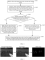
- FIG. 5 is a schematic diagram of a mask image generation process.
- motion vector processing is first performed on the first real image frame to generate the first image, and then the mask image of the first image is determined based on whether the pixels in the first image have color data, in other words, whether the pixels is edge pixels or blank pixels.
- no color data in the pixels in the first image may be understood as that after pixel offset is performed on pixels covered by a dynamic object based on the motion vector and another pixel offset is performed on pixels covered by a static object, neither two offset results cover the pixels, resulting no color data for the pixels.
- the first real image frame may be processed by using a multiple render targets (multiple render targets, MRT) technology, to simultaneously generate the first image and the mask image of the first image.
- MRT multiple render targets
- a stencil buffer of the first real image frame is generated based on the object categories to which the pixels in the first real image frame respectively belong.
- the stencil buffer is queried, and object categories to which pixels in a mask texture image respectively belong are determined.
- a motion vector is used to perform an image warp operation twice on both the first real image frame and the mask texture image to simultaneously generate the first image and the mask image of the first image.
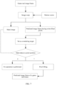
- FIG. 6 is a schematic diagram of another mask image generation process.
- the motion vector when used to perform pixel or pixel block movement on the first real image frame to generate the first image and rendered data of the mask image, data may be simultaneously stored into different internal memory regions using the MRT technology, to simultaneously generate a plurality of different targets. Therefore, in this embodiment, in a process of using the motion vector to perform the image warp operation on the first real image frame, warped image data may be written into different rendering targets using the MRT technology.
- the mask image and the first image (a predicted image frame of the first real image frame) may be bound as the rendering targets simultaneously, so that the mask image and the first image having the to-be-filled pixel region may be generated simultaneously.
- the following uses an execution environment in this embodiment of this application as openGL for description. It may be understood that the execution environment in this embodiment of this application may alternatively be a vulkan environment. This is not limited in this embodiment of this application.
- a principle of simultaneously generating a mask image and a first image based on the MRT technology is as follows.
- S403 Sample mask data of the mask image pixel by pixel to determine whether the pixels in the first image are to-be-filled pixels.
- the pixels in the first image when it is determined whether the pixels in the first image needs to be performed with data filling, it may be determined based on mask data of pixels at corresponding positions in the mask image.
- the mask (Mask) data of the pixels (that is, at the pixel positions) in the mask image may be sampled pixel by pixel to determine whether pixels at corresponding positions in the first image are the to-be-filled pixels.
- a value of the mask data of the pixels in the mask image may first be sampled pixel by pixel. Then, in the mask image, if a value of mask data of a first pixel is equal to a first value, it is determined that a pixel in the first image with a same position as the first pixel is a to-be-filled pixel. If the value of the mask data of the first pixel is equal to a second value, it is determined that the pixel in the first image with the same position as the first pixel is not a to-be-filled pixel.
- the first pixel is any pixel of the mask image.
- the mask image may be a binary image.
- the Mask data of the pixels in the mask image is a value, and is one of two values.
- the value of the Mask data indicates whether the pixel at the corresponding position in the first image needs to be performed with data filling.
- the Mask data is equal to the first value to mark a to-be-filled pixel region in the first image
- the Mask data is equal to the second value to mark a pixel region in the first image where the pixel filling operation does not need to be performed.
- the first value is different from the second value.
- the first value is equal to 1 and the second value is equal to 0.
- the device has the following preset provisions.
- Mask data of a specific pixel is 1, it is determined that a pixel at a corresponding position in the first image is a to-be-filled pixel. If Mask data of a specific pixel is 0, it is determined that a pixel at a corresponding position in the first image is not a to-be-filled pixel.
- the first value is equal to 0 and the second value is equal to 1.
- the device has the following preset provisions. In the mask image, if Mask data of a specific pixel is 0, it is determined that a pixel at a corresponding position in the first image is a to-be-filled pixel. If Mask data of a specific pixel is 1, it is determined that a pixel at a corresponding position in the first image is not a to-be-filled pixel.
- first value and the second value may alternatively be represented by other values or characters.
- first value is identified by character A
- second value is identified by character B
- a specific implementation of the first value and the second value is not limited in this embodiment of this application. This may be set according to an actual requirement. Details are not described herein.
- rendered data at the corresponding position on the first image is retained.
- the mask data is read from the sampled pixel in the mask image, it is determined that the pixel at the corresponding position corresponding to the sampled pixel in the first image is not a to-be-filled pixel, so that the color data is no longer read from the internal memory and a process of writing to the first image is not performed.
- the mask image is a binary image and is a single-channel 8-bit mask image
- memory access overhead is only for an 8-bit read operation.
- the pixel filling operation is performed on the pixel at the corresponding position in the first image.
- a logical process and algorithm of pixel filling are used to obtain the color data of the pixel and write the color data of the pixel to the position of the pixel in the first image.
- S404 Read, for any one of the to-be-filled pixels in the first image, color data of the first real image frame from the internal memory, and use the color data to perform color filling on the to-be-filled pixel in the first image.
- S405 Perform no processing on any effective pixel in the first image, and retain color data of the effective pixel.
- color data of the effective pixels in the first image is retained.
- the first image after being performed with pixel or pixel block movement may be used as a target rendered image.
- the first image is an image having a to-be-filled pixel region.
- a target reference pixel of the to-be-filled pixel may be searched in the first image by moving, and then rendered data of the target reference pixel is determined by reading the internal memory.
- the color data of the first real image frame is stored in the internal memory.
- the pixel filling algorithm is performed by using RGBA four-channel data to calculate color data of the to-be-filled pixel, and a calculation result is written to the pixel at the corresponding position in the first image.
- a complete color image can be obtained, that is, the predicted image frame that can be interpolated between the first real image frame and the second real image frame for display, so that a frame rate of a displayed image can be increased and frame freezing in a picture is reduced.
- the predicted image frame is generated for frame interpolation display to improve a display frame rate of an image.
- the data filling is only performed on the to-be-filled pixels in the first image, and the effective pixels in the first image are retained.
- Intermediate data of the pixel filling algorithm is reused, to significantly reduce a quantity of memory accesses and data volume of a single memory access, effectively reduce power consumption of a device, and resolve a problem of device heating while ensuring integrity of a color of the predicted image frame.
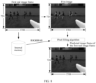
- FIG. 7 is a block flowchart according to the embodiment of FIG. 6 .
- the block flowchart is described by generating a predicted image frame of a game real image frame.
- the game real image frame is a first real image frame
- a mask image is represented by a mask image.
- Mask data of a specific pixel in the mask image being equal to 0 indicates that a pixel at a corresponding position in the predicted image frame having to-be-filled pixels is not a to-be-filled pixel.
- Mask data of a specific pixel in the mask image being equal to 1 indicates that a pixel at a corresponding position in the predicted image frame having to-be-filled pixels is a to-be-filled pixel.
- an image warp operation may be performed on the game real image frame by using the motion vector to generate the mask image and the predicted image frame having to-be-filled pixels. Then, at a pixel filling stage, the predicted image frame having to-be-filled pixels is set as a rendering target. Next, based on mask data read at a pixel position in the mask image, a pixel region in the predicted image frame having to-be-filled pixels that needs to be performed with a pixel filling operation is determined. Finally, the pixel region that needs to be performed with the pixel filling operation is performed with data filling to obtain the predicted image frame of the game real image frame.
- mask data of a specific pixel is equal to 0
- no operation is performed on a pixel at a corresponding position in the predicted image frame having to-be-filled pixels
- color data at the pixel is retained, and mask data of another pixel in the mask image is read. Further, it is determined whether another pixel in the predicted image frame having to-be-filled pixels is performed with the pixel filling operation.
- mask data of a specific pixel is equal to 1
- the pixel filling operation is performed on a pixel at a corresponding position in the predicted image frame having to-be-filled pixels
- generated color data is wrote into the corresponding position of the predicted image frame having to-be-filled pixels
- a value at another pixel position in the mask image is read to determine whether another pixel in the predicted image frame having to-be-filled pixels needs to be performed with the pixel filling operation, until to-be-filled pixels in the predicted image frame having to-be-filled pixels are all processed.
- the following uses a specific example to compare a bandwidth usage of a predicted image frame generation solution provided in this application and a predicted image frame generation solution in the related art for description. It is assumed that a size of an image (a first real image frame, a first image, a mask image, and a predicted image frame of the first real image frame) processed in this application is 1584 (width) ⁇ 720 (height), and a unit is a pixel.
- the first real image frame, the first image, and the predicted image frame include each 4-channel 8-bit RGBA data, a processing rate of a pixel filling operation is 60 (fps), and the mask image includes single-channel 8-bit data represented by 0 or 1.
- FIG. 8 is a schematic diagram of an implementation of a predicted image frame generation solution in the related art.
- a first real image frame is a real image frame
- rendered data of pixels are stored in an internal memory
- the rendered data includes color data.
- color data of the pixels is sequentially read from the internal memory and then rendered into the first image.
- a read operation and a write operation need to be performed separately to obtain a predicted image frame of the first real image frame.
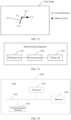
- FIG. 9 is a schematic diagram of an implementation of a predicted image frame generation solution according to an embodiment of this application.
- a first real image frame is a real image frame
- rendered data of pixels are stored in an internal memory
- the rendered data includes color data.
- mask values of pixels in the mask image are first read to determine whether it is necessary to perform a pixel filling operation on a pixel at a corresponding position in the first image.
- the color data of the first real image frame is read from the internal memory based on a pixel filling method, and color data of the pixel is calculated and rendered to the pixel position in the first image to obtain a predicted image frame of the first real image frame.
- the read operation needs to be performed on the 8-bit Mask data once, and then the read operation and the write operation are performed on the 32-bit image data once.
- displacement between a real image frame and a predicted image frame is generally small.
- an area ratio of a to-be-filled pixel region to the first image is equal to 1%.
- the obtained first real image frame is processed to obtain a first image and a mask image of the first image.
- the mask image is used for marking to-be-filled pixels and effective pixels in the first image.
- Mask data of the mask image is sampled pixel by pixel to determine whether pixels in the first image are to-be-filled pixels.
- the mask image is a single-channel 8-bit mask image. Therefore, for the pixels that do not need to be filled in the first image, only a read operation needs to be performed on the 8-bit Mask data once, instead of a read operation and a write operation on 32-bit image data once. This reduces data volume of a memory access.
- FIG. 10 is a schematic flowchart of embodiment 2 of a data processing method according to an embodiment of this application. As shown in FIG. 10 , S402 may be implemented through the following steps.
- S1001 Generate a stencil buffer of the first real image frame based on the object categories to which the pixels in the first real image frame respectively belong.
- a stencil value of a pixel corresponding to a dynamic object is equal to an identifier (a positive integer) of the dynamic object, and a stencil value of a pixel corresponding to a static object is equal to 0.
- the stencil buffer is alternatively an image, and the dynamic object in the first real image frame is marked with a positive integer, and pixels in the static object in the first real image frame are marked with a value of 0.
- stencil values of the pixels when being filled may be set based on whether objects to which the pixels in the first real image frame respectively belong are dynamic objects or static objects.
- an object to which a specific pixel in the first real image frame belongs is a dynamic object, it is determined that the stencil value of the pixel is an identifier (ID) of the object to which the pixel belongs, and the stencil value of the pixel is outputted to the stencil buffer. If an object to which a specific pixel in the first real image frame belongs is a static object, it is determined that the stencil value of the pixel is 0, and 0 is outputted to the stencil buffer.
- ID identifier
- S1002 Generate a mask texture image with all initial values being equal to a first value.
- the first value is used for marking the to-be-filled pixels in the first image.
- a mask texture image may be first created.
- values of pixels in the mask texture image are all initialized to be equal to the first value.
- the first value is equal to 1.
- the stencil buffer of the first real image frame is first queried based on a pixel position of the pixel, and data at a same pixel position is read to obtain an object category to which the pixel belongs, in other words, whether the pixel is a pixel of a dynamic object or a pixel of a static object.
- S1004 Use, based on the object categories to which the pixels respectively belong, a motion vector to perform an image warp operation twice on both the first real image frame and the mask texture image to generate the first image and the mask image of the first image.
- a first image warp (image warp) operation is performed on the first real image frame and the mask texture image, and during image warp manipulation, it is determined whether a current pixel is a static pixel. If it is determined that the current pixel is a static pixel, 0 is outputted to the mask texture image. If it is determined that the current pixel is not a static pixel, no operation is performed. In other words, data of a corresponding pixel position in a corresponding mask texture image is kept as 1. Correspondingly, a warped first real image frame and a warped mask texture image are generated.
- a second image warp operation is performed on the warped first real image frame and the warped mask texture image, and during image warp manipulation, it is determined whether a current pixel is a dynamic pixel. If it is determined that the current pixel is a dynamic pixel, 0 is outputted to the warped mask texture image. Otherwise, no operation is performed. In this case, pixel data of the mask texture image after two warp operations are kept as 1.
- the first real image frame is performed with two warp operations to generate the first image.
- the mask texture image is also performed with two image warp operations to generate the mask image of the first image.
- pixels in the to-be-filled pixel region belong to neither dynamic objects nor static objects, no operation is performed on the pixels in the mask texture image, the data of 1 is retained, and 0 is outputted in another position, so that the mask image of the first image is generated.
- the stencil buffer of the first real image frame is generated based on the object categories to which the pixels in the first real image frame respectively belong, so that the object categories to which the pixels in the mask texture image of which the initial values are all equal to the first value respectively belong may be determined based on the stencil buffer. Further, based on the object categories to which the pixels respectively belong, the motion vector is used to perform the image warp operation twice on both the first real image frame and the mask texture image to generate the first image and the mask image of the first image.
- a specific method of generating a mask image is provided. This lays a foundation for reducing a quantity of memory accesses and volume of memory accesses in the subsequent predicted image frame generation process.
- FIG. 11 is a schematic flowchart of embodiment 3 of a data processing method according to an embodiment of this application. As shown in FIG. 11 , S404 may be implemented through the following steps.
- S1101 Determine at least one candidate reference pixel of the to-be-filled pixel in the first image.
- a position is randomly moved to a first position in the first image with a position of the to-be-filled pixel as a starting point. Then, it is determined whether the first position belongs to a to-be-filled region. If the first position does not belong to the to-be-filled pixel region, it is determined that a pixel at the first position is a candidate reference pixel of the to-be-filled pixel.
- the position is continued to randomly move in the first image with the first position as a starting point until moving to a second position that does not belong to the to-be-filled pixel region, and the second position is determined as the candidate reference pixel of the to-be-filled pixel.
- another candidate reference pixel may be determined in the manner.
- FIG. 12 is a schematic diagram of a process of determining a candidate reference pixel.
- a coordinate point of the to-be-filled pixel is a starting point P_0
- a position is randomly moved a step Offset_0 (O_0) in a direction D_0 to a first position P_i with the coordinate point of the to-be-filled pixel as the starting point P_0, and then it is determined whether the first position P_i is located in the to-be-filled pixel region.
- O_0 Offset_0
- the position is continued to randomly move in a direction, for example, D_1, until moving to a position that is not in the to-be-filled pixel region, that is, an effective pixel position, for example, P_2.
- a pixel at the position P_2 is the candidate reference pixel of the to-be-filled pixel.
- the position coordinate P_2 and the moving direction D_1 of the candidate reference pixel are marked.
- S 1102 Determine a target reference pixel from the at least one candidate reference pixel based on object categories to which candidate reference pixels respectively belong.
- a semantic graph corresponding to a position may be sampled based on the position of the candidate reference pixel, and then it is determined whether the candidate reference pixel is a pixel of a set object category. If it is determined that the candidate reference pixel is the pixel of the set object category, the candidate reference pixel is determined as the target reference pixel. If it is determined that the candidate reference pixel is not the pixel of the set object category, the candidate reference pixel is discarded.
- the semantic graph is an internal memory region which is referred to as a depth stencil buffer set during graphics rendering.
- the depth stencil buffer has two channels. One channel is used for storing a depth of a scene, and the other channel is referred to as a stencil which is a position where semantics are stored.
- a rendering instruction for each object in the image, if shaping data is transmitted in an instruction glStencilFunc(), the shaping data is written to the depth stencil buffer, that is, a stencil channel of a pixel block covered by the object. In this way, stencil data is used as the semantic graph.
- the set object category is the static object.
- candidate reference pixels each are a pixel of the static object. If a specific candidate reference pixel is a pixel of the static object, it is determined that the candidate reference pixel is the target reference pixel. If a specific candidate reference pixel is not a pixel of the static object, in other words, if the candidate reference pixel is a pixel of a dynamic object, the candidate reference pixel is discarded.
- a candidate reference pixel of the dynamic object may also be selected as the target reference pixel. It may be understood that because motion patterns of the dynamic object and the static object are different, when frame prediction is processed, the dynamic object and the static object need to be processed separately. Details are not described herein.
- S1103 Determine, based on a relationship between the target reference pixel and the first real image frame, color data of the target reference pixel by reading the internal memory.
- the color data of the first real image frame is stored in the internal memory.
- the rendered data of the real image frame is to be stored in the internal memory for subsequent use. Therefore, the color data of the first real image frame is stored in the internal memory. Therefore, when the candidate reference pixel is determined as the target reference pixel, the internal memory may be queried based on a position of the target reference pixel in the first image, and the color data of the target reference pixel may be determined from the rendered data of the first real image frame.
- S1104 Determine effective color data of the to-be-filled pixel based on a weight corresponding to the target reference pixel and the color data of the target reference pixel.
- the weight corresponding to the target reference pixel may be determined based on a positional relationship between the target reference pixel and the to-be-filled pixel, and then the color data of the target reference pixel and the weight corresponding to the target reference pixel are summed to determine the effective color data of the target reference pixel.
- S1105 Accumulate the effective color data into existing color data of the to-be-filled pixel until a quantity of color accumulations of the to-be-filled pixel is equal to a first threshold to obtain current color data of the to-be-filled pixel.
- S1106 Divide the current color data by the first threshold to obtain first color data of the to-be-filled pixel.
- the effective color data of the target reference pixel may be accumulated into the existing color data of the to-be-filled pixel, a set displacement is moved in a direction of a first probability with a position of a position coordinate P_i of the target reference pixel as a starting point to find another target pixel (which is also referred to as a target reference pixel) belonging to a set object category, and color data of the another target pixel is accumulated into the existing color data.
- Moving the set displacement in the direction of the first probability may be moving Offset_i in a direction of D_i or moving Offset_i in a random direction D_j . This is not limited in this embodiment. However, a probability of moving Offset_i in the direction of D_i is higher than a probability of moving Offset_i in the random direction of D_j.
- processes from S1101 to S1105 is repeatedly performed a set quantity t of times, in other words, until the quantity of color accumulations of the to-be-filled pixel is equal to the first threshold, to obtain the current color data of the to-be-filled pixel.
- the current color data is divided by the quantity t of accumulations to obtain the first color data of the to-be-filled pixel.
- the pixel of the static object is used as the target reference pixel.
- the color data of the to-be-filled pixel is calculated, the color data of the target reference pixel and the weight corresponding to the target reference pixel may be accumulated into the existing color data of to-be-filled pixel. Then, a position is moved in the direction of the first probability with the position of the position coordinate P_i of the target reference pixel as a starting point to find the pixel belonging to the static object, and pixel data of the static object is accumulated into the existing color data.
- weight data of the target reference pixel is fixed, and is equal to a fixed value generated by mathematical calculation.
- a weight corresponding to the target reference pixel is to take data in this array based on a quantity of steps of P_0 movement.
- the following uses an example of weight distribution corresponding to the static object for description. If a sampling position of the target reference pixel is moved by one step compared with a starting position, the weight corresponding to the target reference pixel is 1.898840. If the sampling position of the target reference pixel is moved by 10 steps compared with the starting position, the corresponding weight is 0.144245.
- weight distribution is not limited in this embodiment of this application, and may be selected according to an actual scenario. Details are not described herein.
- weight of a corresponding position in weight distribution of a dynamic object is generally small.
- a specific value may be determined according to an actual situation. This is not limited herein.
- S 1107 Write the first color data to a position of the to-be-filled pixel in the first image.
- the color data of the to-be-filled pixel may be written to original data where the rendering target covers a pixel at a position corresponding to the rendering target, that is, to the position of the to-be-filled pixel.
- the predicted image frame of the first real image frame may be generated.
- the at least one candidate reference pixel of the to-be-filled pixel is determined in the first image.
- the target reference pixel in the at least one candidate reference pixel is determined based on the object categories to which the candidate reference pixels respectively belong.
- the internal memory is read to determine the color data of the target reference pixel.
- the internal memory stores the rendered data of the first real image frame.
- the effective color data of the to-be-filled pixel is determined based on the weight corresponding to the target reference pixel and the color data of the target reference pixel.
- the effective color data is accumulated into the existing color data of the to-be-filled pixel until the quantity of color accumulations of the to-be-filled pixel is equal to the first threshold to obtain the current color data of the to-be-filled pixel. Finally, the current color data is divided by the first threshold to obtain the first color data of the to-be-filled pixel, and the first color data is written to the position of the to-be-filled pixel in the first image.
- the color data of the target reference pixel is read from the internal memory and intermediate data of a pixel filling algorithm is reused, to significantly reduce a quantity of memory accesses and data volume of a single memory access and effectively reduce power consumption of a device while ensuring integrity of a color of the predicted image frame.
- an apparatus for implementing a data processing method may be divided into functional modules based on the foregoing method examples, for example, each functional module may be obtained through division for each corresponding function, or two or more functions may be integrated into one processing module.
- the integrated module may be implemented in a form of hardware, or may be implemented in a form of a software functional module. It should be noted that in embodiments of this application, the module division is an example, and is merely logical function division, and there may be other division manners during actual implementation.
- FIG. 13 is a schematic diagram of a structure of a data processing apparatus according to an embodiment of this application.
- the data processing apparatus may be implemented by a graphics processing unit GPU in an electronic device.
- the data processing apparatus includes:
- the frame interpolation condition includes that a moving distance between two consecutive real image frames is less than a distance threshold and there is no translucent object in a real image frame.
- the processing unit 1302 is further configured to perform the following operations:
- the filling unit 1303 when the color data of the first real image frame is read from the internal memory, and the color data is used to perform the color filling on the to-be-filled pixel in the first image, the filling unit 1303 is specifically configured to:
- the filling unit 1303 is specifically configured to:
- the filling unit 1303 is specifically configured to:
- the processing unit 1302 when the first real image frame is processed to obtain the first image and the mask image of the first image, the processing unit 1302 is specifically configured to:
- the processing unit 1302 when the first real image frame is processed to obtain the first image and the mask image of the first image, the processing unit 1302 is specifically configured to:
- the processing unit 1302 is specifically configured to:
- the processing unit 1302 when the mask data of the mask image is sampled pixel by pixel to determine whether the pixels in the first image are the to-be-filled pixels, the processing unit 1302 is specifically configured to:
- the mask image is a binary image, the first value is equal to 1, and the second value is equal to 0.
- the data processing apparatus provided in this embodiment of this application may be configured to perform the data processing method shown in FIG. 4 .
- the data processing apparatus provided in this embodiment of this application may be configured to perform the data processing method shown in FIG. 4 .
- FIG. 4 For an implementation principle and an effective effect, refer to the descriptions in the foregoing embodiment. Details are not described herein.
- FIG. 14 is a schematic diagram of a structure of a chip according to an embodiment of this application.
- a chip 1400 includes one or at least two (including two) processors 1401, a communication line 1402, a communication interface 1403, and a memory 1404.
- the processor 1401 is implemented by a GPU, or the processor 1401 is implemented by a CPU and a GPU.
- a memory 1404 stores the following elements: an executable module or a data structure, or subsets thereof, or extended sets thereof.
- the method described in embodiments of this application may be applied to the processor 1401 or implemented by the processor 1401.
- the processor 1401 may be an integrated circuit chip having a capability of processing a signal.
- steps in the foregoing methods can be implemented by using a hardware integrated logical circuit in the processor 1401, or by using instructions in a form of software.
- the processor 1401 may implement or execute various methods, steps, and logic block diagrams related to processing disclosed in this embodiment of this application.
- the steps of the methods disclosed with reference to embodiments of this application may be directly performed and completed by using a hardware decoding processor, or may be performed and completed by using a combination of hardware and software modules in the decoding processor.
- the software module may be located in a mature storage medium in the field such as a random access memory, a read-only memory, a programmable read-only memory, or an electrically erasable programmable memory (electrically erasable programmable read only memory, EEPROM).
- the storage medium is located in the memory 1404, and the processor 1401 reads information in the memory 1404, and completes the steps in the foregoing methods in combination with hardware thereof.
- the processor 1401, the memory 1404, and the communication interface 1403 may communicate with each other via the communication line 1402.
- the instructions executed by the processor stored in the memory may be implemented in the form of a computer program product.
- the computer program product may be pre-written in the memory, or may be downloaded and installed in the memory in the form of software.
- Embodiments of this application further provides a computer program product, including one or more computer instructions.
- the computer may be a general-purpose computer, a special-purpose computer, a computer network, or another programmable apparatus.
- the computer instructions may be stored in a computer-readable storage medium or may be transmitted from a computer-readable storage medium to another computer-readable storage medium.
- the computer instructions may be transmitted from a website, computer, server, or data center to another website, computer, server, or data center in a wired (for example, a coaxial cable, an optical fiber, or a digital subscriber line (digital subscriber line, DSL)) or wireless (for example, infrared, radio, or microwave) manner.
- the computer-readable storage medium may be any usable medium accessible by the computer, or a data storage device, such as a server or a data center, including one or more usable media.
- the usable medium may include a magnetic medium (for example, a floppy disk, a hard disk, or a magnetic tape), an optical medium (for example, a digital versatile disc (digital versatile disc, DVD)), a semi-conductive medium (for example, a solid-state disk (solid-state disk, SSD)), or the like.
- a magnetic medium for example, a floppy disk, a hard disk, or a magnetic tape
- an optical medium for example, a digital versatile disc (digital versatile disc, DVD)
- a semi-conductive medium for example, a solid-state disk (solid-state disk, SSD)
- An embodiment of this application further provides a computer-readable storage medium. All or some of methods in the foregoing embodiments may be implemented by using software, hardware, firmware, or any combination thereof. If implemented in software, the functions may be stored on or transmitted over as one or more instructions or code on a computer-readable medium or a computer-readable medium.
- the computer-readable medium may include a computer storage medium and a communication medium, and may further include any medium that can transmit a computer program from one place to another.
- the storage medium may be any target medium accessible by a computer.
- the computer-readable medium may include a RAM, a ROM, a compact disc read-only memory (compact disc read-only memory, CD-ROM) or another optical disk memory, a magnetic disk memory or another magnetic storage device, or any other medium that is to carry or store required program code in a form of an instruction or a data structure, and may be accessed by a computer.
- any connection is appropriately referred to as a computer-readable medium.
- the coaxial cable, optical fiber cable, twisted pair, DSL, or wireless technologies such as infrared ray, radio, and microwave
- the coaxial cable, optical fiber cable, twisted pair, DSL, or wireless technologies such as infrared ray, radio, and microwave are included in the definition of the medium.
- a magnetic disk and an optical disc used herein include an optical disc, a laser disc, an optical disc, a digital versatile disc (Digital Versatile Disc, DVD), a floppy disk, and a blue ray disc, where the magnetic disk generally reproduces data in a magnetic manner, and the optical disc reproduces data optically by using laser.
- the foregoing combination should also be included in the scope of the computer-readable medium.
- Embodiments of this application are described with reference to the flowcharts and/or block diagrams of the method, the device (system), and the computer program product according to embodiments of this application. It should be understood that computer program instructions can implement each procedure and/or block in the flowcharts and/or block diagrams and a combination of procedures and/or blocks in the flowcharts and/or block diagrams.
- These computer program instructions may be provided for a general-purpose computer, a dedicated computer, an embedded processor, or a processing unit of any other programmable data processing device to generate a machine, so that the instructions executed by a computer or a processing unit of any other programmable data processing device generate an apparatus for implementing a specific function in one or more processes in the flowcharts and/or in one or more blocks in the block diagrams.
Landscapes
- Engineering & Computer Science (AREA)
- Physics & Mathematics (AREA)
- Theoretical Computer Science (AREA)
- General Physics & Mathematics (AREA)
- Multimedia (AREA)
- Signal Processing (AREA)
- Computer Graphics (AREA)
- Computer Vision & Pattern Recognition (AREA)
- Computing Systems (AREA)
- Geometry (AREA)
- Image Processing (AREA)
- Processing Or Creating Images (AREA)
Applications Claiming Priority (2)
| Application Number | Priority Date | Filing Date | Title |
|---|---|---|---|
| CN202211064725.8A CN117670641A (zh) | 2022-08-31 | 2022-08-31 | 数据处理方法、装置、设备及存储介质 |
| PCT/CN2023/095629 WO2024045701A1 (zh) | 2022-08-31 | 2023-05-22 | 数据处理方法、装置、设备及存储介质 |
Publications (2)
| Publication Number | Publication Date |
|---|---|
| EP4455986A1 true EP4455986A1 (de) | 2024-10-30 |
| EP4455986A4 EP4455986A4 (de) | 2025-05-14 |
Family
ID=90066913
Family Applications (1)
| Application Number | Title | Priority Date | Filing Date |
|---|---|---|---|
| EP23858740.6A Pending EP4455986A4 (de) | 2022-08-31 | 2023-05-22 | Datenverarbeitungsverfahren und -vorrichtung sowie vorrichtung und speichermedium |
Country Status (4)
| Country | Link |
|---|---|
| US (1) | US20250166255A1 (de) |
| EP (1) | EP4455986A4 (de) |
| CN (2) | CN117670641A (de) |
| WO (1) | WO2024045701A1 (de) |
Families Citing this family (1)
| Publication number | Priority date | Publication date | Assignee | Title |
|---|---|---|---|---|
| CN118972506A (zh) * | 2024-07-18 | 2024-11-15 | 北京花鸡传媒有限公司 | 一种视频帧剪辑制作处理方法及可读存储介质 |
Family Cites Families (9)
| Publication number | Priority date | Publication date | Assignee | Title |
|---|---|---|---|---|
| JP2002152733A (ja) * | 2000-11-08 | 2002-05-24 | Fujitsu Ltd | 動画像符号化方法、動画像復号化方法、動画像符号化装置、動画像復号化装置、動画像符号化プログラムを記録した記録媒体、動画像復号化プログラムを記録した記録媒体、および動画像符号化データを記録した記録媒体 |
| CN107396111B (zh) * | 2017-07-13 | 2020-07-14 | 河北中科恒运软件科技股份有限公司 | 介导现实中自动视频插帧补偿方法及系统 |
| CN112967356B (zh) * | 2021-03-05 | 2024-12-06 | 北京百度网讯科技有限公司 | 图像填充方法及装置、电子设备和介质 |
| CN112967355B (zh) * | 2021-03-05 | 2024-06-11 | 大连理工大学出版社有限公司 | 图像填充方法及装置、电子设备和介质 |
| US12182955B2 (en) * | 2022-07-26 | 2024-12-31 | Adobe Inc. | Stylized motion effects |
| CN116091329B (zh) * | 2022-08-31 | 2023-10-20 | 荣耀终端有限公司 | 图像处理方法、装置、设备及存储介质 |
| US20240378844A1 (en) * | 2023-05-10 | 2024-11-14 | Google Llc | Bystander and attached shadow removal |
| US12524830B2 (en) * | 2023-11-01 | 2026-01-13 | Qualcomm Incorporated | Occlusion-aware forward warping for video frame interpolation |
| US20250225705A1 (en) * | 2024-12-11 | 2025-07-10 | Dmitry Kozlov | Mixed precision neural network for frame interpolation |
-
2022
- 2022-08-31 CN CN202211064725.8A patent/CN117670641A/zh active Pending
-
2023
- 2023-05-22 EP EP23858740.6A patent/EP4455986A4/de active Pending
- 2023-05-22 CN CN202380063064.3A patent/CN119790425A/zh active Pending
- 2023-05-22 WO PCT/CN2023/095629 patent/WO2024045701A1/zh not_active Ceased
- 2023-05-22 US US18/840,823 patent/US20250166255A1/en active Pending
Also Published As
| Publication number | Publication date |
|---|---|
| WO2024045701A1 (zh) | 2024-03-07 |
| EP4455986A4 (de) | 2025-05-14 |
| CN117670641A (zh) | 2024-03-08 |
| CN119790425A (zh) | 2025-04-08 |
| US20250166255A1 (en) | 2025-05-22 |
| WO2024045701A9 (zh) | 2024-06-13 |
Similar Documents
| Publication | Publication Date | Title |
|---|---|---|
| EP4231242A1 (de) | Grafikwiedergabeverfahren und zugehörige vorrichtung dafür | |
| CN116091329B (zh) | 图像处理方法、装置、设备及存储介质 | |
| CN115661912B (zh) | 图像处理方法、模型训练方法、电子设备及可读存储介质 | |
| WO2023005751A1 (zh) | 渲染方法及电子设备 | |
| US20250166281A1 (en) | Rendering Method and Apparatus, Device, and Storage Medium | |
| EP4455986A1 (de) | Datenverarbeitungsverfahren und -vorrichtung sowie vorrichtung und speichermedium | |
| CN116700554B (zh) | 信息的显示方法、电子设备及可读存储介质 | |
| US20260016935A1 (en) | Display method and related apparatus | |
| CN115018692B (zh) | 一种图像渲染方法及电子设备 | |
| CN116152584B (zh) | 图像处理方法、装置及存储介质 | |
| WO2023280241A1 (zh) | 图像画面渲染方法及电子设备 | |
| CN116688495B (zh) | 帧率调整方法及相关装置 | |
| CN116225274A (zh) | 触控操作的识别方法、装置、电子设备及存储介质 | |
| CN117746762B (zh) | 显示处理方法、装置及电子设备 | |
| CN116688494B (zh) | 生成游戏预测帧的方法和电子设备 | |
| CN116740241B (zh) | 一种图像处理方法及电子设备 | |
| US20250182349A1 (en) | Data processing method and related apparatus | |
| CN119746405B (zh) | 控制方法及电子设备 | |
| CN120459623A (zh) | 图像生成方法、电子设备及计算机可读存储介质 | |
| CN120279066A (zh) | 光流计算方法、终端设备及存储介质 | |
| CN116033281A (zh) | 图像显示方法和电子设备 | |
| CN120762789A (zh) | 应用程序的界面刷新方法、电子设备及存储介质 | |
| CN116048352A (zh) | 展示图切换方法及电子设备 | |
| CN120335906A (zh) | 帧合成方法、电子设备及计算机可读存储介质 | |
| CN116700535A (zh) | 基于笔记应用的悬浮栏显示方法、电子设备以及存储介质 |
Legal Events
| Date | Code | Title | Description |
|---|---|---|---|
| STAA | Information on the status of an ep patent application or granted ep patent |
Free format text: STATUS: THE INTERNATIONAL PUBLICATION HAS BEEN MADE |
|
| PUAI | Public reference made under article 153(3) epc to a published international application that has entered the european phase |
Free format text: ORIGINAL CODE: 0009012 |
|
| STAA | Information on the status of an ep patent application or granted ep patent |
Free format text: STATUS: REQUEST FOR EXAMINATION WAS MADE |
|
| 17P | Request for examination filed |
Effective date: 20240726 |
|
| AK | Designated contracting states |
Kind code of ref document: A1 Designated state(s): AL AT BE BG CH CY CZ DE DK EE ES FI FR GB GR HR HU IE IS IT LI LT LU LV MC ME MK MT NL NO PL PT RO RS SE SI SK SM TR |
|
| A4 | Supplementary search report drawn up and despatched |
Effective date: 20250414 |
|
| RIC1 | Information provided on ipc code assigned before grant |
Ipc: H04N 19/86 20140101ALI20250408BHEP Ipc: H04N 19/80 20140101ALI20250408BHEP Ipc: H04N 19/503 20140101ALI20250408BHEP Ipc: H04N 19/132 20140101ALI20250408BHEP Ipc: G06T 15/20 20110101ALI20250408BHEP Ipc: G06T 1/60 20060101ALI20250408BHEP Ipc: G06T 1/20 20060101AFI20250408BHEP |
|
| STAA | Information on the status of an ep patent application or granted ep patent |
Free format text: STATUS: EXAMINATION IS IN PROGRESS |
|
| 17Q | First examination report despatched |
Effective date: 20250925 |
|
| DAV | Request for validation of the european patent (deleted) | ||
| DAX | Request for extension of the european patent (deleted) |