EP4455751A1 - Optisches kabel und verfahren zur herstellung eines optischen kabels - Google Patents
Optisches kabel und verfahren zur herstellung eines optischen kabels Download PDFInfo
- Publication number
- EP4455751A1 EP4455751A1 EP22911428.5A EP22911428A EP4455751A1 EP 4455751 A1 EP4455751 A1 EP 4455751A1 EP 22911428 A EP22911428 A EP 22911428A EP 4455751 A1 EP4455751 A1 EP 4455751A1
- Authority
- EP
- European Patent Office
- Prior art keywords
- optical fiber
- optical
- stranding
- fiber units
- cable
- Prior art date
- Legal status (The legal status is an assumption and is not a legal conclusion. Google has not performed a legal analysis and makes no representation as to the accuracy of the status listed.)
- Pending
Links
Images

Classifications
-
- G—PHYSICS
- G02—OPTICS
- G02B—OPTICAL ELEMENTS, SYSTEMS OR APPARATUS
- G02B6/00—Light guides; Structural details of arrangements comprising light guides and other optical elements, e.g. couplings
- G02B6/44—Mechanical structures for providing tensile strength and external protection for fibres, e.g. optical transmission cables
- G02B6/4479—Manufacturing methods of optical cables
- G02B6/449—Twisting
-
- G—PHYSICS
- G02—OPTICS
- G02B—OPTICAL ELEMENTS, SYSTEMS OR APPARATUS
- G02B6/00—Light guides; Structural details of arrangements comprising light guides and other optical elements, e.g. couplings
- G02B6/02—Optical fibres with cladding with or without a coating
- G02B6/02214—Optical fibres with cladding with or without a coating tailored to obtain the desired dispersion, e.g. dispersion shifted, dispersion flattened
- G02B6/02285—Characterised by the polarisation mode dispersion [PMD] properties, e.g. for minimising PMD
-
- G—PHYSICS
- G02—OPTICS
- G02B—OPTICAL ELEMENTS, SYSTEMS OR APPARATUS
- G02B6/00—Light guides; Structural details of arrangements comprising light guides and other optical elements, e.g. couplings
- G02B6/44—Mechanical structures for providing tensile strength and external protection for fibres, e.g. optical transmission cables
- G02B6/4401—Optical cables
- G02B6/4403—Optical cables with ribbon structure
-
- G—PHYSICS
- G02—OPTICS
- G02B—OPTICAL ELEMENTS, SYSTEMS OR APPARATUS
- G02B6/00—Light guides; Structural details of arrangements comprising light guides and other optical elements, e.g. couplings
- G02B6/44—Mechanical structures for providing tensile strength and external protection for fibres, e.g. optical transmission cables
- G02B6/4401—Optical cables
- G02B6/441—Optical cables built up from sub-bundles
- G02B6/4413—Helical structure
-
- G—PHYSICS
- G02—OPTICS
- G02B—OPTICAL ELEMENTS, SYSTEMS OR APPARATUS
- G02B6/00—Light guides; Structural details of arrangements comprising light guides and other optical elements, e.g. couplings
- G02B6/44—Mechanical structures for providing tensile strength and external protection for fibres, e.g. optical transmission cables
- G02B6/4479—Manufacturing methods of optical cables
- G02B6/448—Ribbon cables
-
- G—PHYSICS
- G02—OPTICS
- G02B—OPTICAL ELEMENTS, SYSTEMS OR APPARATUS
- G02B6/00—Light guides; Structural details of arrangements comprising light guides and other optical elements, e.g. couplings
- G02B6/44—Mechanical structures for providing tensile strength and external protection for fibres, e.g. optical transmission cables
- G02B6/4479—Manufacturing methods of optical cables
- G02B6/4486—Protective covering
Definitions
- the present disclosure relates to an optical cable and a method for manufacturing the optical cable.
- Patent Literature 1 discloses a unidirectional stranded slot-less optical cable in which polarization mode dispersion (PMD) is reduced.
- Patent Literature 2 discloses an SZ-stranded slot-less optical cable in which PMD is reduced.
- PMD is reduced by setting a twist ratio of a strand, which is a twist amount per unit length of a strand of an optical fiber, to a certain value or more.
- a slot-less optical cable including:
- a method for manufacturing a slot-less optical cable that includes a plurality of optical fiber units each including a plurality of optical fibers, and a cable sheath covering the plurality of optical fiber units, the method including:
- a twist ratio of the strand of the optical fibers is large, a bending tendency of a ribbon increases, and there is a concern that melting workability decreases.
- the twist ratio of the strand is 0.0104 (rad/mm) or more.
- the twist ratio is too large, there is a possibility that the melting workability is deteriorated.
- An object of the present disclosure is to provide an optical cable and a method for manufacturing the optical cable, which are capable of reducing PMD to a low level without deteriorating melting workability.
- an optical cable and a method for manufacturing the optical cable which are capable of reducing PMD to a low level without deteriorating melting workability.
- the twist ratio of the stranding of the plurality of optical fiber units is at least partially set to 0.0014 (rad/mm) or more, PMD of the optical cable can be reduced to 0.1 ps/km 1/2 or less without being greatly twisted.
- a degree of the twist ratio a bending tendency of the plurality of optical fibers increases, and thus melting workability does not decrease.
- the twist ratio is a maximum value of a twist amount per unit length of the optical fiber unit, and is, for example, a maximum value (maximum angle) when a twist amount (angle) of the unit is measured every 1 cm by peeling off a sheath in a range of 1 m.
- the plurality of optical fibers include optical fibers having an outer diameter of 220 ⁇ m or less, and the plurality of optical fibers form an optical fiber ribbon with fiber adhesive parts and non-adhesive parts in which, a coupling portion and a non-coupling portion are intermittently provided in the longitudinal direction in a state where the plurality of optical fibers are arranged in parallel in a direction orthogonal to the longitudinal direction, the coupling portion being a state where adjacent optical fibers of some or all of the plurality of optical fibers are coupled, the non-coupling portion being a state where the adjacent optical fibers are not coupled.
- an upper limit value of the twist ratio is 0.0100 (rad/mm) or less.
- the plurality of optical fiber units are stranded back in the stranding direction.
- a slot-less optical cable that includes a plurality of optical fiber units each including a plurality of optical fibers, and a cable sheath covering the plurality of optical fiber units, the method includes:
- the twist ratio of the stranding of the plurality of optical fiber units is at least partially set to 0.0014 (rad/mm) or more, and thus it is possible to manufacture an optical cable in which PMD is reduced to 0.1 ps/km 1/2 or less.
- an upper limit value of the twist ratio is set to 0.0100 (rad/mm) or less.
- the step of stranding includes a step of stranding back the plurality of optical fiber units in the stranding direction.
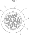
- FIG. 1 is a cross-sectional view, in a direction orthogonal to an axis, of an optical cable 1 according to the present embodiment.
- the optical cable 1 includes a plurality of optical fiber units 2, a water absorbing ribbon 3, a cable sheath 4, tensile strength members 5, and tear strings 6.
- the optical cable 1 is a so-called slot-less optical cable.
- the optical fiber unit 2 includes a plurality of optical fibers.
- An outer diameter of glass fibers provided in the plurality of optical fibers is, for example, 125 ⁇ m.
- An outer diameter of the optical fiber is, for example, any one of 165 ⁇ m, 200 ⁇ m, 220 ⁇ m, and 250 ⁇ m.
- the water absorbing ribbon 3 is wrapped around the entire periphery of the plurality of optical fiber units 2, for example, longitudinally or helically.
- the water absorbing ribbon 3 is, for example, a ribbon subjected to water absorption processing by applying a water absorption powder to a base fabric made of polyester or the like.
- the cable sheath 4 covers the periphery of the water absorbing ribbon 3.
- the cable sheath 4 is made of, for example, a resin such as polyvinyl chloride (PVC) or polyethylene (PE), and is formed by extrusion-molding the resin on the plurality of optical fiber units 2 around which the water absorbing ribbon 3 is wound.
- PVC polyvinyl chloride
- PE polyethylene
- the tensile strength members 5 are embedded in the cable sheath 4.
- the tensile strength members 5 are made of fiber reinforced plastic (FRP) such as aramid FRP, glass FRP, or carbon FRP.
- FRP fiber reinforced plastic
- the tensile strength members 5 may be formed of a liquid crystal polymer.
- the tensile strength members 5 are formed in a circular shape, in a cross-sectional view. Two tensile strength members 5 are provided inside the cable sheath 4 along a longitudinal direction of the optical cable 1.
- the tear strings 6 are for tearing the cable sheath 4, and is embedded in the cable sheath 4 along the longitudinal direction of the optical cable 1.
- two tear strings 6 are provided.
- the two tear strings 6 face each other at substantially intermediate positions of the two tensile strength members 5.
- the tear strings 6 are made of, for example, a plastic material (for example, polyester) resistant to tension.
- the plurality of optical fibers provided in the optical fiber unit 2 form a plurality of optical fiber ribbons 10.
- the plurality of optical fiber ribbons 10 are assembled in a bundled state or stranded state.
- the optical fiber unit 2 may not be in the form of an optical fiber ribbon, and may be an assembly of single optical fibers.
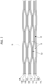
- FIG. 2 is a partially exploded view showing one optical fiber ribbon 10 in the longitudinal direction.
- the optical fiber ribbon 10 is an optical fiber ribbon with fiber adhesive parts and non-adhesive parts in which, in a state where a plurality of optical fibers 11A to 11L are arranged in parallel, a coupling portion 12 in a state where adjacent optical fibers are coupled and a non-coupling portion 13 in a state where adjacent optical fibers are not coupled are intermittently provided in the longitudinal direction. As shown in FIG.
- the coupling portion 12 and the non-coupling portion 13 are intermittently provided between some of the optical fibers (intermittent for every two fibers), but the coupling portion 12 and the non-coupling portion 13 may be intermittently provided between all of the optical fibers (intermittent for every one fiber).
- the optical fiber ribbons 10 in the optical fiber unit 2 may be stranded or may be stranded back.
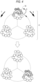
- FIG. 3 is a schematic view showing a configuration in which the optical fiber ribbons 10 in the optical fiber unit 2 are stranded without the optical fiber ribbons 10 being stranded back.
- the optical cable 1 includes twelve optical fiber units 2, one of the twelve optical fiber units 2 is enlarged and shown in FIG. 3 for the sake of description.
- One optical fiber unit 2 is formed of three optical fiber ribbons 10 including twelve fibers. In order to make it easy to visually understand a strand angle of the optical fiber ribbon 10 described below, one of the three optical fiber ribbons 10 is shown in gradation in FIG. 3 .
- the optical fiber ribbons 10 in the optical fiber unit 2 are stranded in a clockwise direction R along the longitudinal direction of the optical cable.
- a strand angle of the optical fiber unit 2 shown in the lower part of FIG. 3 matches the strand angle of the three optical fiber ribbons 10.
- the optical fiber ribbons 10 in the optical fiber unit 2 are stranded in a counterclockwise direction L by periodically reversing the stranding direction. That is, the optical fiber ribbons 10 in the optical fiber unit 2 are SZ-stranded.
- FIG. 4 is a schematic view showing a configuration in which the optical fiber ribbons 10 in the optical fiber unit 2 are stranded while the optical fiber ribbons are stranded back.
- FIG. 4 is an enlarged view of one of the twelve optical fiber units 2 as in FIG. 3 . In order to make it easy to visually understand the strand angle of the optical fiber ribbons 10, one of the three optical fiber ribbons 10 is shown in gradation.
- the optical fiber ribbons 10 are stranded back in a counterclockwise direction S with respect to the stranding direction while being stranded in the clockwise direction R along the longitudinal direction of the optical cable 1.
- stranded back means that the optical fiber ribbons 10 of the optical fiber unit 2 are twisted in a direction to eliminate the twist of each optical fiber ribbon 10 that occurs when the optical fiber ribbons 10 of the optical fiber unit 2 are stranded. That is, when the optical fiber unit 2 before being stranded and the three optical fiber ribbons 10 shown in the upper part of FIG. 4 are used as a reference, the strand angle of the three optical fiber ribbons 10 shown in the lower part of FIG.
- FIG. 4 is smaller than the strand angle of the optical fiber unit 2 by an angle at which the optical fiber ribbons 10 are stranded back.
- a case of the strand back angle equivalent to the strand angle of the optical fiber unit 2 is shown, and a positional relationship of the three optical fiber ribbons 10 in the longitudinal direction of the cable changes, but the directions of the three optical fiber ribbons 10 do not change.
- the twist ratio of the stranding of the plurality of optical fiber units 2 is at least partially 0.0014 (rad/mm) or more. Accordingly, the PMD of the optical cable can be reduced to 0.1 ps/km 1/2 or less.
- the plurality of optical fiber units 2 are stranded while periodically reversing the stranding direction along the longitudinal direction of the optical cable.
- the twist ratio is at least partially set to 0.0014 (rad/mm) or more.
- the water absorbing ribbon 3 is longitudinally or helically wrapped around the periphery of the stranded plurality of optical fiber units 2, and the periphery thereof is covered with the cable sheath 4.
- the twist ratio of the stranding of the plurality of optical fiber units 2 is at least partially set to 0.0014 (rad/mm) or more, and thus it is possible to manufacture an optical cable in which the PMD is reduced to 0.1 ps/km 1/2 or less.
- the twist ratio may be set to 0.0100 (rad/mm) or less. Accordingly, it is possible to manufacture the optical cable 1 that reduces a decrease in melting workability due to an increase in the bending tendency of the plurality of optical fibers.
- the "0.0100 (rad/mm) or less" means that the upper limit value of the twist ratio is 0.0100 (rad/mm), and means that the twist ratio does not exceed 0.0100 (rad/mm) even in a part.
- Table 1 shows evaluation results of the PMD of the optical cable 1 according to the present disclosure.
- an optical fiber having an outer diameter of 200 ⁇ m and an optical fiber ribbon with fiber adhesive parts and non-adhesive parts are used.
- samples 1 to 5 a strand angle for each pitch between optical fiber units is changed to change a twist ratio.
- twist ratio indicates a twist ratio measured in a part of the optical cable 1.
- the SZ-stranding of the optical fiber ribbon in the optical fiber unit and the stranding back of the optical fiber units are performed in samples 1 to 5.
- a plurality of optical cables of such samples are manufactured, the PMD is measured, and a maximum value of the PMD is shown in the table.
- the PMD of the optical cable 1 can be reduced to 0.1 ps/km 1/2 or less.
- the twist ratio of the stranding is set to be larger than 0.0100 (rad/mm) in a part of the optical cable 1, the PMD is smaller, but the melting workability deteriorates.
- the twist ratio of the stranding is set to 0.0100 (rad/mm) or less, it is possible to prevent a decrease in the melting workability due to an increase in the bending tendency of the plurality of optical fibers.
Landscapes
- Physics & Mathematics (AREA)
- General Physics & Mathematics (AREA)
- Optics & Photonics (AREA)
- Engineering & Computer Science (AREA)
- Manufacturing & Machinery (AREA)
- Chemical & Material Sciences (AREA)
- Dispersion Chemistry (AREA)
- Light Guides In General And Applications Therefor (AREA)
- Communication Cables (AREA)
Applications Claiming Priority (2)
| Application Number | Priority Date | Filing Date | Title |
|---|---|---|---|
| JP2021210965 | 2021-12-24 | ||
| PCT/JP2022/047758 WO2023120727A1 (ja) | 2021-12-24 | 2022-12-23 | 光ケーブル及び光ケーブルの製造方法 |
Publications (2)
| Publication Number | Publication Date |
|---|---|
| EP4455751A1 true EP4455751A1 (de) | 2024-10-30 |
| EP4455751A4 EP4455751A4 (de) | 2025-05-07 |
Family
ID=86902892
Family Applications (1)
| Application Number | Title | Priority Date | Filing Date |
|---|---|---|---|
| EP22911428.5A Pending EP4455751A4 (de) | 2021-12-24 | 2022-12-23 | Optisches kabel und verfahren zur herstellung eines optischen kabels |
Country Status (4)
| Country | Link |
|---|---|
| US (1) | US20250138268A1 (de) |
| EP (1) | EP4455751A4 (de) |
| JP (1) | JPWO2023120727A1 (de) |
| WO (1) | WO2023120727A1 (de) |
Families Citing this family (2)
| Publication number | Priority date | Publication date | Assignee | Title |
|---|---|---|---|---|
| WO2025163794A1 (ja) * | 2024-01-31 | 2025-08-07 | 住友電気工業株式会社 | 光ファイバケーブル |
| WO2026022974A1 (ja) * | 2024-07-24 | 2026-01-29 | 住友電気工業株式会社 | 光ケーブル、および、光ケーブルの製造方法 |
Family Cites Families (10)
| Publication number | Priority date | Publication date | Assignee | Title |
|---|---|---|---|---|
| JP2002122762A (ja) | 2000-08-11 | 2002-04-26 | Furukawa Electric Co Ltd:The | 光ファイバケーブル |
| JP2007108424A (ja) * | 2005-10-13 | 2007-04-26 | Sumitomo Electric Ind Ltd | 光ケーブル |
| JP4893024B2 (ja) | 2006-02-24 | 2012-03-07 | 住友電気工業株式会社 | 光ケーブル |
| BRPI0823227A2 (pt) * | 2008-11-07 | 2019-02-26 | Prysmian Spa | cabo óptico, e, rede de distribuição de acesso |
| JP2012027392A (ja) * | 2010-07-27 | 2012-02-09 | Sumitomo Electric Ind Ltd | 光ファイバテープ心線の製造方法および製造装置 |
| WO2017022531A1 (ja) * | 2015-07-31 | 2017-02-09 | 住友電気工業株式会社 | 光ファイバケーブル |
| JP6840659B2 (ja) * | 2017-12-19 | 2021-03-10 | 株式会社フジクラ | 光ファイバケーブル |
| ES2938014T3 (es) * | 2018-10-11 | 2023-04-03 | Fujikura Ltd | Cable de fibra óptica |
| WO2020189772A1 (ja) * | 2019-03-20 | 2020-09-24 | 住友電気工業株式会社 | 間欠連結型光ファイバテープ心線、光ファイバケーブルおよびコネクタ付き光ファイバコード |
| JP7426873B2 (ja) * | 2020-03-27 | 2024-02-02 | 古河電気工業株式会社 | 光ファイバケーブル |
-
2022
- 2022-12-23 EP EP22911428.5A patent/EP4455751A4/de active Pending
- 2022-12-23 JP JP2023569587A patent/JPWO2023120727A1/ja active Pending
- 2022-12-23 US US18/722,699 patent/US20250138268A1/en active Pending
- 2022-12-23 WO PCT/JP2022/047758 patent/WO2023120727A1/ja not_active Ceased
Also Published As
| Publication number | Publication date |
|---|---|
| WO2023120727A1 (ja) | 2023-06-29 |
| JPWO2023120727A1 (de) | 2023-06-29 |
| EP4455751A4 (de) | 2025-05-07 |
| US20250138268A1 (en) | 2025-05-01 |
Similar Documents
| Publication | Publication Date | Title |
|---|---|---|
| EP3879323B1 (de) | Glasfaserkabel | |
| US9651753B2 (en) | Fiber optic ribbon cable | |
| EP1895340B1 (de) | Kabel für einen optischen Wellenleiter mit losen Hohladern | |
| US20060072886A1 (en) | Loose tube optical cable | |
| EP4455751A1 (de) | Optisches kabel und verfahren zur herstellung eines optischen kabels | |
| US4093342A (en) | Optical fiber cable | |
| EP3207415B1 (de) | Glasfaserkabel mit zentraler hohlader | |
| CN101120277A (zh) | 低收缩电信光缆及其制造方法 | |
| EP3304156B1 (de) | Optisches kabel für terrestrische netzwerke | |
| US6553167B2 (en) | Fiber optic cables having ultra-low shrinking filaments and methods of making the same | |
| EP4279965A1 (de) | Faseroptisches kabel und kabel mit verbinder | |
| KR100526506B1 (ko) | 공기압 포설을 위한 광섬유 케이블 | |
| CN102016673A (zh) | 多纤维光缆 | |
| US20220390701A1 (en) | Optical fiber cable and method for manufacturing optical fiber cable | |
| KR102735442B1 (ko) | 광케이블 | |
| US8630521B2 (en) | Optical cable | |
| KR102822837B1 (ko) | 광케이블 | |
| JP2008197258A (ja) | 光ケーブル | |
| CN103097933A (zh) | 塑料光纤单元及使用该塑料光纤单元的塑料光缆 | |
| US20230194817A1 (en) | Optical fiber cable with coil elements | |
| CN116075760A (zh) | 光缆以及光缆制造方法 | |
| CN219512456U (zh) | 一种大芯数分立式生物防护光缆 | |
| CN219641982U (zh) | 一种电梯随行光缆 | |
| US20250004236A1 (en) | Optical cable, optical cable structure, and method for manufacturing optical cable | |
| CA1125554A (en) | Fiber optic cable |
Legal Events
| Date | Code | Title | Description |
|---|---|---|---|
| STAA | Information on the status of an ep patent application or granted ep patent |
Free format text: STATUS: THE INTERNATIONAL PUBLICATION HAS BEEN MADE |
|
| PUAI | Public reference made under article 153(3) epc to a published international application that has entered the european phase |
Free format text: ORIGINAL CODE: 0009012 |
|
| STAA | Information on the status of an ep patent application or granted ep patent |
Free format text: STATUS: REQUEST FOR EXAMINATION WAS MADE |
|
| 17P | Request for examination filed |
Effective date: 20240621 |
|
| AK | Designated contracting states |
Kind code of ref document: A1 Designated state(s): AL AT BE BG CH CY CZ DE DK EE ES FI FR GB GR HR HU IE IS IT LI LT LU LV MC ME MK MT NL NO PL PT RO RS SE SI SK SM TR |
|
| DAV | Request for validation of the european patent (deleted) | ||
| DAX | Request for extension of the european patent (deleted) | ||
| A4 | Supplementary search report drawn up and despatched |
Effective date: 20250404 |
|
| RIC1 | Information provided on ipc code assigned before grant |
Ipc: G02B 6/02 20060101ALI20250331BHEP Ipc: G02B 6/44 20060101AFI20250331BHEP |