EP4455695A1 - Method for correcting soc of battery, and related apparatus - Google Patents
Method for correcting soc of battery, and related apparatus Download PDFInfo
- Publication number
- EP4455695A1 EP4455695A1 EP22909847.0A EP22909847A EP4455695A1 EP 4455695 A1 EP4455695 A1 EP 4455695A1 EP 22909847 A EP22909847 A EP 22909847A EP 4455695 A1 EP4455695 A1 EP 4455695A1
- Authority
- EP
- European Patent Office
- Prior art keywords
- battery cell
- soc value
- value
- battery
- calculated
- Prior art date
- Legal status (The legal status is an assumption and is not a legal conclusion. Google has not performed a legal analysis and makes no representation as to the accuracy of the status listed.)
- Pending
Links
Images

Classifications
-
- G—PHYSICS
- G01—MEASURING; TESTING
- G01R—MEASURING ELECTRIC VARIABLES; MEASURING MAGNETIC VARIABLES
- G01R31/00—Arrangements for testing electric properties; Arrangements for locating electric faults; Arrangements for electrical testing characterised by what is being tested not provided for elsewhere
- G01R31/36—Arrangements for testing, measuring or monitoring the electrical condition of accumulators or electric batteries, e.g. capacity or state of charge [SoC]
- G01R31/396—Acquisition or processing of data for testing or for monitoring individual cells or groups of cells within a battery
-
- G—PHYSICS
- G01—MEASURING; TESTING
- G01R—MEASURING ELECTRIC VARIABLES; MEASURING MAGNETIC VARIABLES
- G01R31/00—Arrangements for testing electric properties; Arrangements for locating electric faults; Arrangements for electrical testing characterised by what is being tested not provided for elsewhere
- G01R31/36—Arrangements for testing, measuring or monitoring the electrical condition of accumulators or electric batteries, e.g. capacity or state of charge [SoC]
- G01R31/382—Arrangements for monitoring battery or accumulator variables, e.g. SoC
- G01R31/3828—Arrangements for monitoring battery or accumulator variables, e.g. SoC using current integration
-
- G—PHYSICS
- G01—MEASURING; TESTING
- G01R—MEASURING ELECTRIC VARIABLES; MEASURING MAGNETIC VARIABLES
- G01R31/00—Arrangements for testing electric properties; Arrangements for locating electric faults; Arrangements for electrical testing characterised by what is being tested not provided for elsewhere
- G01R31/36—Arrangements for testing, measuring or monitoring the electrical condition of accumulators or electric batteries, e.g. capacity or state of charge [SoC]
- G01R31/382—Arrangements for monitoring battery or accumulator variables, e.g. SoC
- G01R31/3842—Arrangements for monitoring battery or accumulator variables, e.g. SoC combining voltage and current measurements
-
- G—PHYSICS
- G01—MEASURING; TESTING
- G01R—MEASURING ELECTRIC VARIABLES; MEASURING MAGNETIC VARIABLES
- G01R31/00—Arrangements for testing electric properties; Arrangements for locating electric faults; Arrangements for electrical testing characterised by what is being tested not provided for elsewhere
- G01R31/36—Arrangements for testing, measuring or monitoring the electrical condition of accumulators or electric batteries, e.g. capacity or state of charge [SoC]
- G01R31/382—Arrangements for monitoring battery or accumulator variables, e.g. SoC
- G01R31/3835—Arrangements for monitoring battery or accumulator variables, e.g. SoC involving only voltage measurements
-
- Y—GENERAL TAGGING OF NEW TECHNOLOGICAL DEVELOPMENTS; GENERAL TAGGING OF CROSS-SECTIONAL TECHNOLOGIES SPANNING OVER SEVERAL SECTIONS OF THE IPC; TECHNICAL SUBJECTS COVERED BY FORMER USPC CROSS-REFERENCE ART COLLECTIONS [XRACs] AND DIGESTS
- Y02—TECHNOLOGIES OR APPLICATIONS FOR MITIGATION OR ADAPTATION AGAINST CLIMATE CHANGE
- Y02E—REDUCTION OF GREENHOUSE GAS [GHG] EMISSIONS, RELATED TO ENERGY GENERATION, TRANSMISSION OR DISTRIBUTION
- Y02E60/00—Enabling technologies; Technologies with a potential or indirect contribution to GHG emissions mitigation
- Y02E60/10—Energy storage using batteries
-
- Y—GENERAL TAGGING OF NEW TECHNOLOGICAL DEVELOPMENTS; GENERAL TAGGING OF CROSS-SECTIONAL TECHNOLOGIES SPANNING OVER SEVERAL SECTIONS OF THE IPC; TECHNICAL SUBJECTS COVERED BY FORMER USPC CROSS-REFERENCE ART COLLECTIONS [XRACs] AND DIGESTS
- Y02—TECHNOLOGIES OR APPLICATIONS FOR MITIGATION OR ADAPTATION AGAINST CLIMATE CHANGE
- Y02T—CLIMATE CHANGE MITIGATION TECHNOLOGIES RELATED TO TRANSPORTATION
- Y02T10/00—Road transport of goods or passengers
- Y02T10/60—Other road transportation technologies with climate change mitigation effect
- Y02T10/70—Energy storage systems for electromobility, e.g. batteries
Definitions
- the present application relates to the technical field of battery management and, more particularly, to a method for correcting an SOC of a battery and, related apparatus.
- a state of charge (SOC) of a battery system and various levels of components thereof refers to a ratio of a remaining battery capacity to a rated electric capacity.
- the SOC is a key indicator for determining whether the battery system can operate safely and reliably, and whether the battery system can be managed and controlled accurately. Accurately estimating the SOC of the battery is one of the most important functions of a battery management system (BMS).
- BMS battery management system
- Constant current voltage (CCV) correction is one of the most important correction methods.
- the CCV curve can represent a corresponding relationship between the SOC of the battery and a voltage.
- an SOC value of the CCV curve corresponding to the voltage is used as a target corrected value.
- a minimum cell voltage changes slowly due to the battery polarity, and the SOC obtained by looking up a CCV curve by using the minimum cell voltage does not correspond to an SOC value obtained by the actual integration of a charging current, which leads to the problem of false correction.
- the present application discloses a method for correcting an SOC of a battery and related apparatus, which may solve the problem of low accuracy of the prior art in estimating the SOC of the battery.
- an embodiment of the present application provides a method for correcting an SOC of a battery.
- the method is applied to a battery, the battery including a plurality of battery cells.
- the method for correcting the SOC of the battery includes:
- the step of correcting a calculated SOC value of the second battery cell according to the target SOC value and a calculated SOC value of the first battery cell to obtain a corrected SOC value of the second battery cell comprises: acquiring a difference between the target SOC value and the calculated SOC value of the first battery cell; and adding the calculated SOC value of the second battery cell with the difference to obtain the corrected SOC value of the second battery cell.
- the method further comprises: taking the target SOC value as a corrected SOC value of the first battery cell.
- the step of acquiring the calculated SOC value of the first battery cell and the calculated SOC value of the second battery cell comprises: acquiring the calculated SOC value of the first battery cell and the calculated SOC value of the second battery cell through an ampere-hour integration method.
- the step of acquiring the calculated SOC value of the first battery cell and the calculated SOC value of the second battery cell through the ampere-hour integration method comprises:
- the step of correcting a calculated SOC value of the second battery cell according to the target SOC value and a calculated SOC value of the first battery cell comprises:
- the present application discloses an apparatus for correcting an SOC of a battery.
- the apparatus includes:
- the correction module is configured to:
- the present application discloses a vehicle, the vehicle including a controlling apparatus, wherein the controlling apparatus includes a memory, a processor and a computer program which is stored in the memory and capable of operating on the processor, and the processor implements the steps of the method in the first aspect or any possible embodiment mode in the first aspect while executing the computer program.
- the controlling apparatus includes a memory, a processor and a computer program which is stored in the memory and capable of operating on the processor, and the processor implements the steps of the method in the first aspect or any possible embodiment mode in the first aspect while executing the computer program.
- an embodiment of the present application provides a computer-readable storage medium.
- the computer-readable storage medium is configured to store a computer program, wherein the computer program is executed by a processor to implement the steps of the method in the first aspect or any possible embodiment mode in the first aspect.
- the method for correcting the SOC of the battery provided by the present application has the beneficial effects: the method provided by the present application is used for correcting the SOC of the battery through the following steps: acquiring a measured voltage of each battery cell in sequence; determining a maximum voltage value and a first battery cell corresponding to the maximum voltage value as well as a minimum voltage value and a second battery cell corresponding to the minimum voltage value according to the measured voltage of each battery cell; determining a target SOC value according to the maximum voltage value and a preset CCV curve; and correcting a calculated SOC value of the second battery cell according to the target SOC value and a calculated SOC value of the first battery cell to obtain a corrected SOC value of the second battery cell.
- a voltage difference between a maximum voltage cell and a minimum voltage cell is considered when an SOC of the minimum voltage cell is corrected. Since the voltage value of the battery cell with the minimum voltage changes slow, using the voltage value of the battery cell with the minimum voltage may lead to false correction.
- the problem of false correction caused by using a voltage value of a battery cell with a minimum voltage to look up the CCV curve and obtain the corrected SOC value can be avoided.
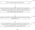
- FIG. 1 an implementation flowchart of a method for correcting an SOC of a battery provided by an embodiment of the present application is shown.
- the method shown in FIG. 1 is applied to a battery including a plurality of battery cells and consists of four steps, S101 to S104, each of which is described in detail below.
- the measured voltage of each battery cell may be acquired in real time through a voltage sensor.
- the maximum voltage value U max is determined according to the measured voltage of each battery cell, and the battery cell corresponding to the maximum voltage value is determined to be a first battery cell.
- the minimum voltage value U min is determined, and the battery cell corresponding to the minimum voltage value is determined to be a second battery cell.
- the CCV curve can represent a corresponding relationship between the SOC of the battery and a voltage.
- the SOC value corresponding to the maximum voltage value U max is obtained by looking up the CCV curve, and the value is the target SOC value SOC target .
- the method has the following disadvantage: due to the polarity of the battery, the minimum cell voltage changes slowly. Therefore, in the method (1), an SOC obtained by looking up the CCV curve using the minimum cell voltage does not correspond to an SOC value obtained by the actual integration of a charging current, and the problem of false correction will be caused if the value is used to correct the minimum SOC.
- the method has the following disadvantage: in the method (2), a target SOC value is obtained by simply looking up the CCV curve according to the maximum value of the measured voltage, and if the currently calculated minimum SOC value is forcibly increased according to the SOC value, the SOC correction will lose a differential pressure characteristic, resulting in false correction. If the characteristics of respective cell cores are inconsistent in the later stage, forcibly increasing the SOC value of the core with low voltage will lead to an over-discharge problem.
- a difference between the SOC value (i.e., the target SOC value) obtained by looking up a table and the calculated SOC value may be determined according to a target SOC value and a calculated SOC value of the maximum voltage cell. Further, the calculated SOC value of the minimum voltage cell can be corrected based on the difference.
- the method avoids the problem of an inaccurate SOC value caused by looking up the CCV curve due to a minimum voltage cell and slow voltage conversion, and on the other hand, also avoids the problem of losing a differential voltage characteristic caused by directly looking up the CCV curve by the maximum voltage cell and obtaining the target SOC value to correct the calculated SOC value of the minimum voltage cell.
- a difference between the calculated SOC value of the first battery cell and the calculated SOC value of the second battery cell is calculated, and the corrected SOC value of the second battery cell is obtained by subtracting the difference from the target SOC value.
- the difference between the target SOC value and the calculated SOC value of the first battery cell is acquired; and the corrected SOC value of the second battery cell is obtained by adding the calculated SOC value of the second battery cell with the difference.
- the target SOC value is taken as the corrected SOC value of the first battery cell.
- the calculated SOC value of the first battery cell and the calculated SOC value of the second battery cell are acquired through an ampere-hour integration method.
- an SOC of a lithium-ion battery cannot be directly measured, but can only be estimated by parameters such as a battery terminal voltage, a charging/discharging current, and an internal resistance.
- the calculated SOC value of each battery cell is acquired through the ampere-hour integration method. Before the ampere-hour integration method is used, an initial SOC value of the battery cell needs to be obtained.
- the ampere-hour integration method may be used to calculate a cumulative charge ampere-hour or a cumulative discharge ampere-hour obtained by the integration of current and time of the battery cell within a period of time, and combined with the above-mentioned initial SOC value, the calculated SOC value of the battery at the current moment can be obtained by using the ampere-hour integration method.
- the calculation accuracy of the ampere-hour integration method depends on the accuracy of the initial SOC value of the battery cell.
- the accurate calculated SOC value can be obtained just by ensuring an accurate initial SOC value. If there is a deviation in the initial SOC value, an error of the calculated SOC value will accumulate and become larger, resulting in low accuracy of the calculated SOC value.
- the method provided by the previous embodiment further includes the following steps: determining whether a standing duration of the battery before the start of the present charge and discharge has reached a preset duration; if it is determined that the standing duration of the battery before the start of the present charge and discharge is larger than or equal to the preset duration, acquiring an open circuit voltage of the battery cell for each battery cell, and determining an initial SOC value of the battery cell according to the open circuit voltage of the battery cell; and if it is determined that the standing duration of the battery before the start of the present charge and discharge is less than the preset duration, reading an SOC value of the battery cell in a preset storage space when the battery is powered off last time, the SOC value being used as the initial SOC value of the battery cell.
- the standing duration refers to a duration of a battery pack system corresponding to the battery from a last power-off and shutdown moment to the present start-up moment.
- the open circuit voltage refers to a static open circuit voltage of a core. Polarization will occur to the core after charging or discharging. At this time, an external characteristic voltage of the core is inconsistent with the static open circuit voltage of the cell, so it is necessary to let the core stand for a certain period of time to eliminate polarization.
- a voltage after standing is the static open circuit voltage (i.e., OCV).
- the battery has an ohmic resistance and a polarization resistance inside, and leads to hysteresis caused by electrochemical polarization and concentration polarization, so a stable terminal voltage needs to be obtained by standing and evenly distributing electrolyte inside the battery.
- the initial SOC value of the battery is obtained by looking up an OCV-SOC table. In this case, the initial SOC value is more accurate.
- the SOC value of the battery cell is read in the preset storage space when the battery is powered off last time, the SOC value being used as the initial SOC value of the battery cell.
- the initial SOC value of the battery is obtained by looking up the OCV-SOC table, which has low accuracy and will lead to a large error.
- a calculated SOC value of the first battery cell and a calculated SOC value of the second battery cell may be calculated through the ampere-hour integration method according to the initial SOC value of the first battery cell and the initial SOC value of the second battery cell.
- the initial SOC value obtained by the first two steps has high accuracy. Therefore, the calculated SOC value of the first battery cell and the calculated SOC value of the second battery cell, which are calculated here, are both highly accurate.
- calculating the calculated SOC value of the first battery cell and the calculated SOC value of the second battery cell through the ampere-hour integration method according to the initial SOC value of the first battery cell and the initial SOC value of the second battery cell includes:
- the method provided by the present application can implement the correction of the SOC of the battery through the following steps: acquiring a measured voltage of each battery cell in sequence; determining a maximum voltage value and a first battery cell corresponding to the maximum voltage value as well as a minimum voltage value and a second battery cell corresponding to the minimum voltage value according to the measured voltage of each battery cell; determining a target SOC value according to the maximum voltage value and a preset CCV curve; and correcting a calculated SOC value of the second battery cell according to the target SOC value and a calculated SOC value of the first battery cell to obtain a corrected SOC value of the second battery cell.
- a voltage difference between a maximum voltage cell and a minimum voltage cell is considered when an SOC of the minimum voltage cell is corrected. Since the voltage value of the battery cell with the minimum voltage changes slow, using the voltage value of the battery cell with the minimum voltage may lead to false correction.
- the problem of false correction caused by using a voltage value of a battery cell with a minimum voltage to look up the CCV curve and obtain the corrected SOC value can be avoided.
- FIG. 2 shows the structural composition of an apparatus for correcting an SOC of a battery provided by an embodiment of the present application. For ease of description, only the parts related to the present application are shown in FIG. 2 , and details are described below.
- the apparatus 2 for correcting the SOC of the battery includes a voltage acquisition module 21, a first determining module 22, a second determining module 23 and a correction module 24.
- the voltage acquisition module 21 is configured to acquire a measured voltage of each battery cell.
- the first determining module 22 is configured to determine a maximum voltage value and a first battery cell corresponding to the maximum voltage value, as well as a minimum voltage value and a second battery cell corresponding to the minimum voltage value according to the measured voltage of each battery cell.
- the second determining module 23 is configured to determine a target SOC value according to the maximum voltage value and a preset CCV curve.
- the correction module 24 is further configured to correct a calculated SOC value of the second battery cell according to a target SOC value and a calculated SOC value of the first battery cell to obtain a corrected SOC value of the second battery cell.
- the apparatus 2 is capable of correcting the SOC of the battery by performing the following steps: acquiring a measured voltage of each battery cell in sequence; determining a maximum voltage value and a first battery cell corresponding to the maximum voltage value as well as a minimum voltage value and a second battery cell corresponding to the minimum voltage value according to the measured voltage of each battery cell; determining a target SOC value according to the maximum voltage value and a preset CCV curve; and correcting a calculated SOC value of the second battery cell according to the target SOC value and a calculated SOC value of the first battery cell to obtain a corrected SOC value of the second battery cell.
- a voltage difference between a maximum voltage cell and a minimum voltage cell is considered when an SOC of the minimum voltage cell is corrected. Since the voltage value of the battery cell with the minimum voltage changes slow, using the voltage value of the battery cell with the minimum voltage may lead to false correction.
- the problem of false correction caused by using a voltage value of a battery cell with a minimum voltage to look up the CCV curve and obtain the corrected SOC value can be avoided.
- the correction module 24 is configured to:
- the correction module 24 is configured to: take the target SOC value as a corrected SOC value of the first battery cell.
- the correction module 24 is configured to: acquire the calculated SOC value of the first battery cell and the calculated SOC value of the second battery cell through an ampere-hour integration method.
- the correction module 24 is configured to:
- the correction module 24 is configured to:
- the apparatus for correcting the SOC of the battery provided by the above several possible embodiments may be configured to perform the method embodiment for correcting the SOC of the battery. Their implementation principles and technical effects are similar, and thus are not repeated.
- FIG. 3 is a schematic diagram of the structural composition of the controlling apparatus provided by an embodiment of the present application.
- the controlling apparatus 3 includes a processor 30, a memory 31 and a computer program 32 which is stored in the memory 31 and capable of operating on the processor 30.
- the processor 30 implements the steps (e.g., S101 to S104 shown in FIG. 1 ) in each of the above method embodiments for correcting the SOC of the battery while executing the computer program 32.
- the processor 30 implements the functions (e.g., the functions of units 21 to 24 shown in FIG. 2 ) of various modules/units in the above apparatus embodiment while executing the computer program 32.
- the computer program 32 may be divided into one or more modules/units, wherein the one or more modules/units can be stored in the memory 31, and executed by the processor 30 to complete the technical solutions provided by the respective embodiments of the present application.
- These modules/units may be a series of computer program instruction segments capable of completing a particular function, these instruction segments being configured to describe an execution process of the computer program 32 in the controlling apparatus 3.
- the controlling apparatus 3 may be a hardware part of a battery management system (BMS) or a part of the hardware part.
- the controlling apparatus 3 may include, but is not limited to, a processor 30 and a memory 31.
- FIG. 3 is only an example of the controlling apparatus 3 and does not constitute a limitation of the controlling apparatus 3.
- the controlling apparatus 3 may include more or less components than those illustrated, or combine some components or adopt different components.
- the controlling apparatus 3 may also include an input/output device, a network access device, a bus and the like.
- the processor 30 may be a central processing unit (CPU), a universal processor, a digital signal processor (DSP), an application specific integrated circuit (ASIC), a field-programmable gate array (FPGA), or other programmable logic devices, discrete gates or transistor logic devices, discrete hardware components, or the like.
- the universal processor may be a microprocessor, or any conventional processor.
- the memory 31 may be an internal storage unit of the controlling apparatus 3, such as a hard disk or memory of the controlling apparatus 3.
- the memory 31 may also be an external storage device of the controlling apparatus 3, such as a pluggable hard disk, a smart memory card (SMC), a secure digital (SD) card or a flash card equipped on the controlling apparatus 3. Further, the memory 31 may also include both an internal storage unit and an external storage device of the controlling apparatus 3.
- the memory 31 is configured to store a computer program 32 as well as other programs and data required by the controlling apparatus 3.
- the memory 31 may also be configured to temporarily store data that has been or will be outputted.
- the disclosed devices/electronic devices and methods can be implemented in other ways.
- the embodiments of the device/electronic device described above is only illustrative.
- the division of the modules or units is only a logical functional division, and there may be other ways of division in actual implementation.
- multiple units or components can be combined or integrated into another system, or some features can be ignored or not executed.
- the mutual coupling or direct coupling or communication connection displayed or discussed can be indirect coupling or communication connection through some interfaces, devices or units, which can be electrical, mechanical or other forms.
- the units described as separate components may or may not be physically separated, and the components displayed as units may or may not be physical units. That is, the above components and units can be located in one place or distributed across multiple network units. Some or all of the units can be selected according to actual needs to achieve the goals of various solutions of the embodiments.
- integrated modules/units When integrated modules/units are implemented in the form of software functional units and sold or used as independent products, they can be stored in a computer-readable storage medium. Based on the understanding, the present application implements all or part of the processes in the above-mentioned method embodiments, which can be completed by controlling the relevant hardware through the computer programs.
- the computer program can be stored in a computer-readable storage medium, and when executed by a processor, it can implement the steps of the various acceleration control methods of the vehicle described above.
- the computer programs include computer program codes, which can be in the form of source codes, object codes, executable files, or some intermediate forms.
- the computer-readable medium can include: any entity or device capable of carrying the computer program codes, recording mediums, USB flash drives, portable hard drives, magnetic disks, optical disks, computer memory, read-only memory (ROM), random access memory (RAM), electric carrier signals, telecommunications signals, and software distribution medium.
- ROM read-only memory
- RAM random access memory
- electric carrier signals telecommunications signals
- software distribution medium any entity or device capable of carrying the computer program codes, recording mediums, USB flash drives, portable hard drives, magnetic disks, optical disks, computer memory, read-only memory (ROM), random access memory (RAM), electric carrier signals, telecommunications signals, and software distribution medium.
- the content contained in the computer-readable medium can be appropriately added or removed according to the requirements of legislation and patent practice within the jurisdiction.
- the computer-readable medium do not include the electric carrier signals and the telecommunications signals.
Landscapes
- Physics & Mathematics (AREA)
- General Physics & Mathematics (AREA)
- Secondary Cells (AREA)
- Charge And Discharge Circuits For Batteries Or The Like (AREA)
Abstract
Description
- The patent application claims the priority of the Chinese patent application filed on December 24th, 2021 with the application number of CN202111604024.4, which is incorporated herein in its entirety by reference.
- The present application relates to the technical field of battery management and, more particularly, to a method for correcting an SOC of a battery and, related apparatus.
- A state of charge (SOC) of a battery system and various levels of components thereof refers to a ratio of a remaining battery capacity to a rated electric capacity. The SOC is a key indicator for determining whether the battery system can operate safely and reliably, and whether the battery system can be managed and controlled accurately. Accurately estimating the SOC of the battery is one of the most important functions of a battery management system (BMS).
- However, due to the high degree of nonlinearity in the actual use of the battery, it is usually necessary to correct an estimated SOC value in real time through an optimization algorithm to ensure the accuracy of the SOC estimation. Constant current voltage (CCV) correction is one of the most important correction methods.
- The CCV curve can represent a corresponding relationship between the SOC of the battery and a voltage. In the existing CCV correction method, an SOC value of the CCV curve corresponding to the voltage is used as a target corrected value. When the SOC is corrected by the CCV correction method in the conventional technology, a minimum cell voltage changes slowly due to the battery polarity, and the SOC obtained by looking up a CCV curve by using the minimum cell voltage does not correspond to an SOC value obtained by the actual integration of a charging current, which leads to the problem of false correction.
- In view of this, the present application discloses a method for correcting an SOC of a battery and related apparatus, which may solve the problem of low accuracy of the prior art in estimating the SOC of the battery.
- In a first aspect, an embodiment of the present application provides a method for correcting an SOC of a battery. The method is applied to a battery, the battery including a plurality of battery cells. The method for correcting the SOC of the battery includes:
- acquiring a measured voltage of each battery cell;
- determining a maximum voltage value and a first battery cell corresponding to the maximum voltage value as well as a minimum voltage value and a second battery cell corresponding to the minimum voltage value according to the measured voltage of each battery cell;
- determining a target SOC value according to the maximum voltage value and a preset CCV curve; and
- correcting a calculated SOC value of the second battery cell according to the target SOC value and a calculated SOC value of the first battery cell to obtain a corrected SOC value of the second battery cell.
- In a possible embodiment, the step of correcting a calculated SOC value of the second battery cell according to the target SOC value and a calculated SOC value of the first battery cell to obtain a corrected SOC value of the second battery cell comprises:
acquiring a difference between the target SOC value and the calculated SOC value of the first battery cell; and
adding the calculated SOC value of the second battery cell with the difference to obtain the corrected SOC value of the second battery cell. - In a possible embodiment, the method further comprises:
taking the target SOC value as a corrected SOC value of the first battery cell. - In a possible embodiment, the step of acquiring the calculated SOC value of the first battery cell and the calculated SOC value of the second battery cell comprises:
acquiring the calculated SOC value of the first battery cell and the calculated SOC value of the second battery cell through an ampere-hour integration method. - In a possible embodiment, the step of acquiring the calculated SOC value of the first battery cell and the calculated SOC value of the second battery cell through the ampere-hour integration method comprises:
- determining whether a standing duration of the battery before a start of the present charge and discharge reaches a preset duration;
- if it is determined that the standing duration of the battery before the start of the present charge and discharge is larger than or equal to the preset duration, acquiring, for each battery cell, an open circuit voltage of the battery cell, and determining an initial SOC value of the battery cell according to the open circuit voltage of the battery cell;
- if it is determined that the standing duration of the battery before the start of the present charge and discharge is less than the preset duration, reading, for each battery cell, an SOC value of the battery cell in a preset storage space when the battery is powered off last time, the SOC value being used as the initial SOC value of the battery cell; and
- calculating a calculated SOC value of the first battery cell and a calculated SOC value of the second battery cell through an ampere-hour integration method according to the initial SOC value of the first battery cell and the initial SOC value of the second battery cell.
- In a possible embodiment, the step of calculating the calculated SOC value of the first battery cell and the calculated SOC value of the second battery cell through the ampere-hour integration method according to the initial SOC value of the first battery cell and the initial SOC value of the second battery cell comprises:
for each battery cell in the first battery cell and each battery cell in the second battery cell, acquiring a calculated SOC value of the battery cell through a preset formula, the preset formula being: [0026]

- In a possible embodiment, the step of correcting a calculated SOC value of the second battery cell according to the target SOC value and a calculated SOC value of the first battery cell comprises:
- acquiring a difference between the calculated SOC value of the first battery cell and the calculated SOC value of the second battery cell; and
- obtaining the corrected SOC value of the second battery cell by subtracting the difference from the target SOC value.
- In a second aspect, the present application discloses an apparatus for correcting an SOC of a battery. The apparatus includes:
- a voltage acquisition module, a first determining module, a second determining module and a correction module, wherein
- the voltage acquisition module is configured to acquire a measured voltage of each battery cell in sequence;
- the first determining module is configured to determine a maximum voltage value and a first battery cell corresponding to the maximum voltage value as well as a minimum voltage value and a second battery cell corresponding to the minimum voltage value according to the measured voltage of each battery cell;
- the second determining module is configured to determine a target SOC value according to the maximum voltage value and a preset CCV curve; and
- the correction module is configured to correct a calculated SOC value of the second battery cell according to the target SOC value and a calculated SOC value of the first battery cell to obtain a corrected SOC value of the second battery cell.
- In a possible embodiment, the correction module is configured to:
- acquire a difference between the target SOC value and the calculated SOC value of the first battery cell; and
- add the calculated SOC value of the second battery cell with the difference to obtain the corrected SOC value of the second battery cell.
- In a third aspect, the present application discloses a vehicle, the vehicle including a controlling apparatus, wherein the controlling apparatus includes a memory, a processor and a computer program which is stored in the memory and capable of operating on the processor, and the processor implements the steps of the method in the first aspect or any possible embodiment mode in the first aspect while executing the computer program.
- In a fourth aspect, an embodiment of the present application provides a computer-readable storage medium. The computer-readable storage medium is configured to store a computer program, wherein the computer program is executed by a processor to implement the steps of the method in the first aspect or any possible embodiment mode in the first aspect.
- Compared with the conventional technology, the method for correcting the SOC of the battery provided by the present application has the beneficial effects:
the method provided by the present application is used for correcting the SOC of the battery through the following steps: acquiring a measured voltage of each battery cell in sequence; determining a maximum voltage value and a first battery cell corresponding to the maximum voltage value as well as a minimum voltage value and a second battery cell corresponding to the minimum voltage value according to the measured voltage of each battery cell; determining a target SOC value according to the maximum voltage value and a preset CCV curve; and correcting a calculated SOC value of the second battery cell according to the target SOC value and a calculated SOC value of the first battery cell to obtain a corrected SOC value of the second battery cell. In the process of correcting the SOC of the battery through the above steps, a voltage difference between a maximum voltage cell and a minimum voltage cell is considered when an SOC of the minimum voltage cell is corrected. Since the voltage value of the battery cell with the minimum voltage changes slow, using the voltage value of the battery cell with the minimum voltage may lead to false correction. In the present application, by using the method above, the problem of false correction caused by using a voltage value of a battery cell with a minimum voltage to look up the CCV curve and obtain the corrected SOC value can be avoided. - In order to more clearly illustrate the technical solutions of the embodiments of the present application, the figures that are required to describe the embodiments or the prior art will be briefly described below. Apparently, the figures that are described below are merely some embodiments of the present application, and a person skilled in the art can obtain other figures according to these figures without paying creative work.
-
FIG. 1 is an implementation flowchart of a method for correcting an SOC of a battery provided by an embodiment of the present application; -
FIG. 2 is a schematic diagram of the structural composition of an apparatus for correcting an SOC of a battery provided by an embodiment of the present application; and -
FIG. 3 is a schematic diagram of the structural composition of a controlling apparatus provided by an embodiment of the present application. - In the following description, specific details such as specific system structures and technologies are provided for illustrating purposes rather than limitation, to facilitate a thorough understanding of the embodiments of the present application. However, persons skilled in the art should be understood that the present application can also be implemented in other embodiments without these specific details. In other cases, detailed descriptions of well-known systems, devices, circuits, and methods are omitted to avoid unnecessary details hindering the description of the present application.
- In order to clarify the purpose, technical solution, and advantages of the present application, specific embodiments will be described below in conjunction with the accompanying drawings.
- Referring to
FIG. 1 , an implementation flowchart of a method for correcting an SOC of a battery provided by an embodiment of the present application is shown. The method shown inFIG. 1 is applied to a battery including a plurality of battery cells and consists of four steps, S101 to S104, each of which is described in detail below. - In S101, acquiring a measured voltage of each battery cell.
- In this step, the measured voltage of each battery cell may be acquired in real time through a voltage sensor.
- In S102, according to the measured voltage of each battery cell, determining a maximum voltage value and a first battery cell corresponding to the maximum voltage value, as well as a minimum voltage value and a second battery cell corresponding to the minimum voltage value.
- In this step, the maximum voltage value U max is determined according to the measured voltage of each battery cell, and the battery cell corresponding to the maximum voltage value is determined to be a first battery cell. In addition, the minimum voltage value U min is determined, and the battery cell corresponding to the minimum voltage value is determined to be a second battery cell.
- In S103, determining a target SOC value according to the maximum voltage value and a preset CCV curve.
- The CCV curve can represent a corresponding relationship between the SOC of the battery and a voltage.
- In this step, the SOC value corresponding to the maximum voltage value U max is obtained by looking up the CCV curve, and the value is the target SOC value SOC target.
- In S104, correcting a calculated SOC value of the second battery cell according to the target SOC value and a calculated SOC value of the first battery cell to obtain a corrected SOC value of the second battery cell.
- When the SOC is corrected by using the CCV correction method in the prior art, the following two methods are often adopted.
- (1) looking up a CCV curve according to a maximum value and a minimum value of a measured voltage to obtain corresponding maximum and minimum SOC values respectively; correcting a currently calculated SOC maximum value by using the obtained maximum SOC value; and correcting a currently calculated SOC minimum value by using the obtained minimum SOC value.
- The method has the following disadvantage: due to the polarity of the battery, the minimum cell voltage changes slowly. Therefore, in the method (1), an SOC obtained by looking up the CCV curve using the minimum cell voltage does not correspond to an SOC value obtained by the actual integration of a charging current, and the problem of false correction will be caused if the value is used to correct the minimum SOC.
- (2) correcting the currently calculated maximum and minimum SOC values at the same time according to the maximum value of the measured voltage.
obtaining an SOC value by looking up the CCV curve according to the maximum value of the measured voltage, and the value is used to correct the currently calculated maximum and minimum SOC values at the same time. - The method has the following disadvantage: in the method (2), a target SOC value is obtained by simply looking up the CCV curve according to the maximum value of the measured voltage, and if the currently calculated minimum SOC value is forcibly increased according to the SOC value, the SOC correction will lose a differential pressure characteristic, resulting in false correction. If the characteristics of respective cell cores are inconsistent in the later stage, forcibly increasing the SOC value of the core with low voltage will lead to an over-discharge problem.
- In the four steps shown in
FIG. 1 , a difference between the SOC value (i.e., the target SOC value) obtained by looking up a table and the calculated SOC value may be determined according to a target SOC value and a calculated SOC value of the maximum voltage cell. Further, the calculated SOC value of the minimum voltage cell can be corrected based on the difference. The method, on the one hand, avoids the problem of an inaccurate SOC value caused by looking up the CCV curve due to a minimum voltage cell and slow voltage conversion, and on the other hand, also avoids the problem of losing a differential voltage characteristic caused by directly looking up the CCV curve by the maximum voltage cell and obtaining the target SOC value to correct the calculated SOC value of the minimum voltage cell. - In a possible embodiment, a difference between the calculated SOC value of the first battery cell and the calculated SOC value of the second battery cell is calculated, and the corrected SOC value of the second battery cell is obtained by subtracting the difference from the target SOC value.
- In another possible embodiment, the difference between the target SOC value and the calculated SOC value of the first battery cell is acquired; and the corrected SOC value of the second battery cell is obtained by adding the calculated SOC value of the second battery cell with the difference.
- In a possible embodiment, the target SOC value is taken as the corrected SOC value of the first battery cell.
- In a possible embodiment, the calculated SOC value of the first battery cell and the calculated SOC value of the second battery cell are acquired through an ampere-hour integration method.
- As a highly complex nonlinear system, an SOC of a lithium-ion battery cannot be directly measured, but can only be estimated by parameters such as a battery terminal voltage, a charging/discharging current, and an internal resistance.
- In the embodiment, the calculated SOC value of each battery cell is acquired through the ampere-hour integration method. Before the ampere-hour integration method is used, an initial SOC value of the battery cell needs to be obtained. The ampere-hour integration method may be used to calculate a cumulative charge ampere-hour or a cumulative discharge ampere-hour obtained by the integration of current and time of the battery cell within a period of time, and combined with the above-mentioned initial SOC value, the calculated SOC value of the battery at the current moment can be obtained by using the ampere-hour integration method. Therefore, for any battery cell, when the calculated SOC value of the battery cell is obtained by the ampere-hour integration method, an accurate calculated SOC value of the battery cell can be obtained only when the initial SOC value of the battery cell is accurate and the integration process of the battery cell is accurate.
- In other words, the calculation accuracy of the ampere-hour integration method depends on the accuracy of the initial SOC value of the battery cell. The accurate calculated SOC value can be obtained just by ensuring an accurate initial SOC value. If there is a deviation in the initial SOC value, an error of the calculated SOC value will accumulate and become larger, resulting in low accuracy of the calculated SOC value.
- In a possible embodiment, in order to obtain the accurate initial SOC value of the battery cell, the method provided by the previous embodiment further includes the following steps: determining whether a standing duration of the battery before the start of the present charge and discharge has reached a preset duration; if it is determined that the standing duration of the battery before the start of the present charge and discharge is larger than or equal to the preset duration, acquiring an open circuit voltage of the battery cell for each battery cell, and determining an initial SOC value of the battery cell according to the open circuit voltage of the battery cell; and if it is determined that the standing duration of the battery before the start of the present charge and discharge is less than the preset duration, reading an SOC value of the battery cell in a preset storage space when the battery is powered off last time, the SOC value being used as the initial SOC value of the battery cell.
- In the embodiment, the standing duration refers to a duration of a battery pack system corresponding to the battery from a last power-off and shutdown moment to the present start-up moment.
- The open circuit voltage (OCV) refers to a static open circuit voltage of a core. Polarization will occur to the core after charging or discharging. At this time, an external characteristic voltage of the core is inconsistent with the static open circuit voltage of the cell, so it is necessary to let the core stand for a certain period of time to eliminate polarization. A voltage after standing is the static open circuit voltage (i.e., OCV). The battery has an ohmic resistance and a polarization resistance inside, and leads to hysteresis caused by electrochemical polarization and concentration polarization, so a stable terminal voltage needs to be obtained by standing and evenly distributing electrolyte inside the battery.
- In the embodiment, if it is determined that the standing duration of the battery before the start of the present charge and discharge has reached the preset duration, the initial SOC value of the battery is obtained by looking up an OCV-SOC table. In this case, the initial SOC value is more accurate.
- If it is determined that the standing duration of the battery before the start of the present charge and discharge is less than the preset duration, for each battery cell, the SOC value of the battery cell is read in the preset storage space when the battery is powered off last time, the SOC value being used as the initial SOC value of the battery cell. In this case, the initial SOC value of the battery is obtained by looking up the OCV-SOC table, which has low accuracy and will lead to a large error.
- In the embodiment, after the initial SOC value of the first battery cell and the initial SOC value of the second battery cell are obtained, a calculated SOC value of the first battery cell and a calculated SOC value of the second battery cell may be calculated through the ampere-hour integration method according to the initial SOC value of the first battery cell and the initial SOC value of the second battery cell. The initial SOC value obtained by the first two steps has high accuracy. Therefore, the calculated SOC value of the first battery cell and the calculated SOC value of the second battery cell, which are calculated here, are both highly accurate.
- In a possible embodiment, in the previous embodiment, calculating the calculated SOC value of the first battery cell and the calculated SOC value of the second battery cell through the ampere-hour integration method according to the initial SOC value of the first battery cell and the initial SOC value of the second battery cell includes:
- for each battery cell in the first battery cell and the second battery cell, acquiring a calculated SOC value of the battery cell through a preset formula, the preset formula being as follows:

- in which: SOC is the calculated SOC value of the battery cell; SOC 0 is an initial SOC value of the battery cell; CN is a rated capacity of the battery cell; and I is a current of this battery cell. When the battery cell is in a charging process, a value of I is negative. When the battery cell is in a discharging process, a value of I is positive. An absolute value of

- As can be seen from the above description, the method provided by the present application can implement the correction of the SOC of the battery through the following steps: acquiring a measured voltage of each battery cell in sequence; determining a maximum voltage value and a first battery cell corresponding to the maximum voltage value as well as a minimum voltage value and a second battery cell corresponding to the minimum voltage value according to the measured voltage of each battery cell; determining a target SOC value according to the maximum voltage value and a preset CCV curve; and correcting a calculated SOC value of the second battery cell according to the target SOC value and a calculated SOC value of the first battery cell to obtain a corrected SOC value of the second battery cell. In the process of correcting the SOC of the battery through the above steps, a voltage difference between a maximum voltage cell and a minimum voltage cell is considered when an SOC of the minimum voltage cell is corrected. Since the voltage value of the battery cell with the minimum voltage changes slow, using the voltage value of the battery cell with the minimum voltage may lead to false correction. In the present application, by using the method above, the problem of false correction caused by using a voltage value of a battery cell with a minimum voltage to look up the CCV curve and obtain the corrected SOC value can be avoided.
- It should be understood that the magnitudes of serial numbers of each step in the above embodiment does not mean an order of execution, and the order of execution of each process should be determined by its function and internal logic, but shall not constitute any limitation on the implementation process in the embodiment of the present application.
- The following is an embodiment of a device of the present application. Details not described in detail may refer to the corresponding method embodiment described above.
-
FIG. 2 shows the structural composition of an apparatus for correcting an SOC of a battery provided by an embodiment of the present application. For ease of description, only the parts related to the present application are shown inFIG. 2 , and details are described below. - As shown in
FIG. 2 , theapparatus 2 for correcting the SOC of the battery includes avoltage acquisition module 21, a first determiningmodule 22, a second determiningmodule 23 and acorrection module 24. - The
voltage acquisition module 21 is configured to acquire a measured voltage of each battery cell. - The first determining
module 22 is configured to determine a maximum voltage value and a first battery cell corresponding to the maximum voltage value, as well as a minimum voltage value and a second battery cell corresponding to the minimum voltage value according to the measured voltage of each battery cell. - The second determining
module 23 is configured to determine a target SOC value according to the maximum voltage value and a preset CCV curve. - The
correction module 24 is further configured to correct a calculated SOC value of the second battery cell according to a target SOC value and a calculated SOC value of the first battery cell to obtain a corrected SOC value of the second battery cell. - The
apparatus 2 provided by the present application is capable of correcting the SOC of the battery by performing the following steps: acquiring a measured voltage of each battery cell in sequence; determining a maximum voltage value and a first battery cell corresponding to the maximum voltage value as well as a minimum voltage value and a second battery cell corresponding to the minimum voltage value according to the measured voltage of each battery cell; determining a target SOC value according to the maximum voltage value and a preset CCV curve; and correcting a calculated SOC value of the second battery cell according to the target SOC value and a calculated SOC value of the first battery cell to obtain a corrected SOC value of the second battery cell. In the process of correcting the SOC of the battery through the above steps, a voltage difference between a maximum voltage cell and a minimum voltage cell is considered when an SOC of the minimum voltage cell is corrected. Since the voltage value of the battery cell with the minimum voltage changes slow, using the voltage value of the battery cell with the minimum voltage may lead to false correction. In the present application, by using the method above, the problem of false correction caused by using a voltage value of a battery cell with a minimum voltage to look up the CCV curve and obtain the corrected SOC value can be avoided. - In a possible embodiment, the
correction module 24 is configured to: - acquire a difference between the target SOC value and the calculated SOC value of the first battery cell; and
- add the calculated SOC value of the second battery cell with the difference to obtain the corrected SOC value of the second battery cell.
- In a possible embodiment, the
correction module 24 is configured to:
take the target SOC value as a corrected SOC value of the first battery cell. - In a possible embodiment, the
correction module 24 is configured to:
acquire the calculated SOC value of the first battery cell and the calculated SOC value of the second battery cell through an ampere-hour integration method. - In a possible embodiment, the
correction module 24 is configured to: - determine whether a standing duration of the battery before the start of the present charge and discharge has reached a preset duration;
- if it is determined that the standing duration of the battery before the start of the present charge and discharge is larger than or equal to the preset duration, acquire, for each battery cell, an open circuit voltage of the battery cell, and determine an initial SOC value of the battery cell according to the open circuit voltage of the battery cell;
- if it is determined that the standing duration of the battery before the start of the present charge and discharge is less than the preset duration, read, for each battery cell, an SOC value of the battery cell in a preset storage space when the battery is powered off last time, the SOC value being used as the initial SOC value of the battery cell; and
- calculate a calculated SOC value of the first battery cell and a calculated SOC value of the second battery cell through an ampere-hour integration method according to the initial SOC value of the first battery cell and the initial SOC value of the second battery cell.
- In a possible embodiment, the
correction module 24 is configured to: - for each battery cell in the first battery cell and the second battery cell, acquire a calculated SOC value of the battery cell through a preset formula, the preset formula being as follows:

- in which: SOC is the calculated SOC value of the battery cell; SOC 0 is an initial SOC value of the battery cell; CN is a rated capacity of the battery cell; and I is a current of the battery cell. When the battery cell is in a charging process, a value of I is negative. When the battery cell is in a discharging process, a value of I is positive. An absolute value of

- The apparatus for correcting the SOC of the battery provided by the above several possible embodiments may be configured to perform the method embodiment for correcting the SOC of the battery. Their implementation principles and technical effects are similar, and thus are not repeated.
- The present application further provides a vehicle. The vehicle includes a controlling apparatus.
FIG. 3 is a schematic diagram of the structural composition of the controlling apparatus provided by an embodiment of the present application. As shown inFIG. 3 , thecontrolling apparatus 3 includes aprocessor 30, amemory 31 and acomputer program 32 which is stored in thememory 31 and capable of operating on theprocessor 30. Theprocessor 30 implements the steps (e.g., S101 to S104 shown inFIG. 1 ) in each of the above method embodiments for correcting the SOC of the battery while executing thecomputer program 32. Alternatively, theprocessor 30 implements the functions (e.g., the functions ofunits 21 to 24 shown inFIG. 2 ) of various modules/units in the above apparatus embodiment while executing thecomputer program 32. - Exemplarily, the
computer program 32 may be divided into one or more modules/units, wherein the one or more modules/units can be stored in thememory 31, and executed by theprocessor 30 to complete the technical solutions provided by the respective embodiments of the present application. These modules/units may be a series of computer program instruction segments capable of completing a particular function, these instruction segments being configured to describe an execution process of thecomputer program 32 in thecontrolling apparatus 3. - The
controlling apparatus 3 may be a hardware part of a battery management system (BMS) or a part of the hardware part. Thecontrolling apparatus 3 may include, but is not limited to, aprocessor 30 and amemory 31. Those skilled in the art can understand thatFIG. 3 is only an example of thecontrolling apparatus 3 and does not constitute a limitation of thecontrolling apparatus 3. Thecontrolling apparatus 3 may include more or less components than those illustrated, or combine some components or adopt different components. For example, thecontrolling apparatus 3 may also include an input/output device, a network access device, a bus and the like. - The
processor 30 may be a central processing unit (CPU), a universal processor, a digital signal processor (DSP), an application specific integrated circuit (ASIC), a field-programmable gate array (FPGA), or other programmable logic devices, discrete gates or transistor logic devices, discrete hardware components, or the like. The universal processor may be a microprocessor, or any conventional processor. - The
memory 31 may be an internal storage unit of thecontrolling apparatus 3, such as a hard disk or memory of thecontrolling apparatus 3. Thememory 31 may also be an external storage device of thecontrolling apparatus 3, such as a pluggable hard disk, a smart memory card (SMC), a secure digital (SD) card or a flash card equipped on thecontrolling apparatus 3. Further, thememory 31 may also include both an internal storage unit and an external storage device of thecontrolling apparatus 3. Thememory 31 is configured to store acomputer program 32 as well as other programs and data required by thecontrolling apparatus 3. Thememory 31 may also be configured to temporarily store data that has been or will be outputted. - Persons skilled in the art can clearly understand that, for the sake of convenience and simplicity in description, only the division of the above functional units and modules will be illustrated with examples. In practical applications, the above function allocation can be completed by different functional units or modules as needed, that is, the internal structure of the device can be divided into different functional units or modules to complete all or part of the functions described above. The various functional units and modules in the embodiments can be integrated into one processing unit, or they can exist separately physically, or two or more units can be integrated into one unit. The integrated units mentioned above can be implemented in the form of hardware or software functional units. In addition, the specific names of each functional unit and module are only for the purpose of distinguishing them from each other and are not intended to limit the scope of protection of the present application. The specific working process of the units and modules in the above device can refer to the corresponding process in the embodiments of the aforementioned method, and will not be repeated here.
- In the above embodiments, the descriptions of the embodiments have their own emphasis. For the parts that are not detailed or recorded in one embodiment, please refer to the relevant descriptions of other embodiments.
- Persons skilled in the art can realize that the units and algorithm steps described in the embodiments disclosed in the present application can be implemented through the electronic hardware, or a combination of the computer software and the electronic hardware. Whether these functions are executed in the hardware or the software depends on the specific application and design constraint conditions of the technical solution. Persons skilled in the art can use different methods to achieve the described functions for each specific application, but these implementation methods should not be considered beyond the scope of the present application.
- In the embodiments provided in the present application, it should be understood that the disclosed devices/electronic devices and methods can be implemented in other ways. For example, the embodiments of the device/electronic device described above is only illustrative. For example, the division of the modules or units is only a logical functional division, and there may be other ways of division in actual implementation. For example, multiple units or components can be combined or integrated into another system, or some features can be ignored or not executed. On the other hand, the mutual coupling or direct coupling or communication connection displayed or discussed can be indirect coupling or communication connection through some interfaces, devices or units, which can be electrical, mechanical or other forms.
- The units described as separate components may or may not be physically separated, and the components displayed as units may or may not be physical units. That is, the above components and units can be located in one place or distributed across multiple network units. Some or all of the units can be selected according to actual needs to achieve the goals of various solutions of the embodiments.
- When integrated modules/units are implemented in the form of software functional units and sold or used as independent products, they can be stored in a computer-readable storage medium. Based on the understanding, the present application implements all or part of the processes in the above-mentioned method embodiments, which can be completed by controlling the relevant hardware through the computer programs. The computer program can be stored in a computer-readable storage medium, and when executed by a processor, it can implement the steps of the various acceleration control methods of the vehicle described above. Among them, the computer programs include computer program codes, which can be in the form of source codes, object codes, executable files, or some intermediate forms. The computer-readable medium can include: any entity or device capable of carrying the computer program codes, recording mediums, USB flash drives, portable hard drives, magnetic disks, optical disks, computer memory, read-only memory (ROM), random access memory (RAM), electric carrier signals, telecommunications signals, and software distribution medium. It should be noted that the content contained in the computer-readable medium can be appropriately added or removed according to the requirements of legislation and patent practice within the jurisdiction. For example, in some jurisdictions, according to the legislation and the patent practice, the computer-readable medium do not include the electric carrier signals and the telecommunications signals.
- The above embodiments are merely intended to explain the technical solutions of the present application, and not to limit them. Although the present application is explained in detail with reference to the above embodiments, a person skilled in the art should understand that he can still modify the technical solutions set forth by the above embodiments, or make equivalent substitutions to part of the technical features of them. However, those modifications or substitutions do not make the essence of the corresponding technical solutions depart from the spirit and scope of the technical solutions of the embodiments of the present application.
Claims (11)
- A method for correcting a state of charge (SOC) of a battery, which is applied to a battery including a plurality of battery cells, the method comprising:acquiring a measured voltage of each battery cell;according to the measured voltage of each battery cell, determining a maximum voltage value and a first battery cell corresponding to the maximum voltage value as well as a minimum voltage value and a second battery cell corresponding to the minimum voltage value;determining a target SOC value according to the maximum voltage value and a preset constant current voltage (CCV) curve; andcorrecting a calculated SOC value of the second battery cell according to the target SOC value and a calculated SOC value of the first battery cell to obtain a corrected SOC value of the second battery cell.
- The method according to claim 1, wherein the step of correcting a calculated SOC value of the second battery cell according to the target SOC value and a calculated SOC value of the first battery cell to obtain a corrected SOC value of the second battery cell comprises:acquiring a difference between the target SOC value and the calculated SOC value of the first battery cell; andadding the calculated SOC value of the second battery cell with the difference to obtain the corrected SOC value of the second battery cell.
- The method according to claim 1 or 2, further comprising:
taking the target SOC value as a corrected SOC value of the first battery cell. - The method according to claim 1 or 2, wherein the step of acquiring the calculated SOC value of the first battery cell and the calculated SOC value of the second battery cell comprises:
acquiring the calculated SOC value of the first battery cell and the calculated SOC value of the second battery cell through an ampere-hour integration method. - The method according to claim 4, wherein the step of acquiring the calculated SOC value of the first battery cell and the calculated SOC value of the second battery cell through the ampere-hour integration method comprises:determining whether a standing duration of the battery before a start of the present charge and discharge reaches a preset duration;if it is determined that the standing duration of the battery before the start of the present charge and discharge is larger than or equal to the preset duration, acquiring, for each battery cell, an open circuit voltage of the battery cell, and determining an initial SOC value of the battery cell according to the open circuit voltage of the battery cell;if it is determined that the standing duration of the battery before the start of the present charge and discharge is less than the preset duration, reading, for each battery cell, an SOC value of the battery cell in a preset storage space when the battery is powered off last time, the SOC value being used as the initial SOC value of the battery cell; andcalculating a calculated SOC value of the first battery cell and a calculated SOC value of the second battery cell through an ampere-hour integration method according to the initial SOC value of the first battery cell and the initial SOC value of the second battery cell.
- The method according to claim 5, wherein the step of calculating the calculated SOC value of the first battery cell and the calculated SOC value of the second battery cell through the ampere-hour integration method according to the initial SOC value of the first battery cell and the initial SOC value of the second battery cell comprises:for each battery cell in the first battery cell and each battery cell in the second battery cell, acquiring a calculated SOC value of the battery cell through a preset formula, the preset formula being:
 in which: SOC is the calculated SOC value of the battery cell; SOC 0 is an initial SOC value of the battery cell; CN is a rated capacity of the battery cell; and I is a current of the battery cell; when the battery cell is in a charging process, a value of I is negative; when the battery cell is in a discharging process, a value of I is positive; an absolute value of
- The method according to claim 1, wherein the step of correcting a calculated SOC value of the second battery cell according to the target SOC value and a calculated SOC value of the first battery cell comprises:acquiring a difference between the calculated SOC value of the first battery cell and the calculated SOC value of the second battery cell; andobtaining the corrected SOC value of the second battery cell by subtracting the difference from the target SOC value.
- An apparatus for correcting a state of charge (SOC) of a battery, comprising a voltage acquisition module, a first determining module, a second determining module and a correction module, whereinthe voltage acquisition module is configured to acquire a measured voltage of each battery cell in sequence;the first determining module is configured to, according to the measured voltage of each battery cell, determine a maximum voltage value and a first battery cell corresponding to the maximum voltage value as well as a minimum voltage value and a second battery cell corresponding to the minimum voltage value;the second determining module is configured to determine a target SOC value according to the maximum voltage value and a preset constant current voltage (CCV) curve; andthe correction module is configured to correct a calculated SOC value of the second battery cell according to the target SOC value and a calculated SOC value of the first battery cell to obtain a corrected SOC value of the second battery cell.
- The apparatus according to claim 8, wherein the correction module is configured to:acquire a difference between the target SOC value and the calculated SOC value of the first battery cell; andadd the calculated SOC value of the second battery cell with the difference to obtain the corrected SOC value of the second battery cell.
- A vehicle, comprising a controlling apparatus, wherein the controlling apparatus comprises a memory, a processor, and a computer program which is stored in the memory and operable on the processor, the processor being configured to implement the steps of the method according to any one of claims 1 to 7 when executing the computer program.
- A computer-readable storage medium, having stored a computer program therein, the computer program being executed by a processor to implement the steps of the method according to any one of claims 1 to 7.
Applications Claiming Priority (2)
| Application Number | Priority Date | Filing Date | Title |
|---|---|---|---|
| CN202111604024.4A CN115113061B (en) | 2021-12-24 | 2021-12-24 | Method and related device for correcting battery SOC |
| PCT/CN2022/139035 WO2023116533A1 (en) | 2021-12-24 | 2022-12-14 | Method for correcting soc of battery, and related apparatus |
Publications (2)
| Publication Number | Publication Date |
|---|---|
| EP4455695A1 true EP4455695A1 (en) | 2024-10-30 |
| EP4455695A4 EP4455695A4 (en) | 2025-04-23 |
Family
ID=83324984
Family Applications (1)
| Application Number | Title | Priority Date | Filing Date |
|---|---|---|---|
| EP22909847.0A Pending EP4455695A4 (en) | 2021-12-24 | 2022-12-14 | METHOD FOR CORRECTING THE CHARGE STATUS OF A BATTERY AND ASSOCIATED DEVICE |
Country Status (3)
| Country | Link |
|---|---|
| EP (1) | EP4455695A4 (en) |
| CN (1) | CN115113061B (en) |
| WO (1) | WO2023116533A1 (en) |
Families Citing this family (1)
| Publication number | Priority date | Publication date | Assignee | Title |
|---|---|---|---|---|
| CN115113061B (en) * | 2021-12-24 | 2024-11-22 | 长城汽车股份有限公司 | Method and related device for correcting battery SOC |
Family Cites Families (18)
| Publication number | Priority date | Publication date | Assignee | Title |
|---|---|---|---|---|
| KR101990975B1 (en) * | 2012-04-13 | 2019-06-19 | 삼성전자 주식회사 | Gradation voltage generator and display driving apparatus |
| JP6221237B2 (en) * | 2013-01-21 | 2017-11-01 | 株式会社豊田自動織機 | CHARGE RATE ESTIMATION DEVICE AND CHARGE RATE ESTIMATION METHOD |
| CN105742741B (en) * | 2016-04-08 | 2018-03-27 | 深圳市清友能源技术有限公司 | A kind of SOC control method for correcting |
| CN106054085B (en) * | 2016-07-11 | 2019-11-15 | 四川普力科技有限公司 | A method for estimating battery SOC based on temperature |
| CN106526495A (en) * | 2016-11-22 | 2017-03-22 | 深圳市沃特玛电池有限公司 | Battery pack SOC evaluation method and battery pack SOC evaluation system |
| CN107294186A (en) * | 2017-08-11 | 2017-10-24 | 安徽华凯新能源科技有限公司 | Anti-explosion battery group based on SOC curve amendments |
| CN107959070B (en) * | 2017-10-30 | 2019-11-05 | 安徽江淮汽车集团股份有限公司 | A kind of SOC modification method and battery management system |
| CN109975708B (en) * | 2017-12-26 | 2022-04-29 | 宇通客车股份有限公司 | An automatic online correction method for battery SOC |
| CN109532559B (en) * | 2018-11-14 | 2020-09-15 | 北汽福田汽车股份有限公司 | SOC correction method and device of power battery and vehicle |
| CN109633460B (en) * | 2018-12-27 | 2021-03-19 | 东风航盛(武汉)汽车控制系统有限公司 | Universal battery state-of-charge capacity estimation method |
| CN109613432A (en) * | 2019-01-08 | 2019-04-12 | 广州小鹏汽车科技有限公司 | Method, apparatus, and computer-readable storage medium for estimating battery state of charge |
| JP7136048B2 (en) * | 2019-08-21 | 2022-09-13 | トヨタ自動車株式会社 | Control device |
| CN110888060B (en) * | 2019-11-20 | 2021-10-15 | 先进储能材料国家工程研究中心有限责任公司 | Ni-MH battery pack SOC correction method |
| US20230170727A1 (en) * | 2020-04-27 | 2023-06-01 | Nissan Motor Co., Ltd. | Output Control Method for Secondary Battery and Output Control System for Secondary Battery |
| CN113097582B (en) * | 2021-03-30 | 2022-07-12 | 阳光储能技术有限公司 | Method and device for estimating SOH value of battery monomer |
| CN113253114B (en) * | 2021-04-09 | 2022-08-23 | 深圳市誉娇诚科技有限公司 | Dynamic correction and estimation method for SOC of power battery |
| CN113824189B (en) * | 2021-10-18 | 2024-03-19 | 国网黑龙江省电力有限公司电力科学研究院 | A multi-stage charging system for lithium-ion batteries |
| CN115113061B (en) * | 2021-12-24 | 2024-11-22 | 长城汽车股份有限公司 | Method and related device for correcting battery SOC |
-
2021
- 2021-12-24 CN CN202111604024.4A patent/CN115113061B/en active Active
-
2022
- 2022-12-14 EP EP22909847.0A patent/EP4455695A4/en active Pending
- 2022-12-14 WO PCT/CN2022/139035 patent/WO2023116533A1/en not_active Ceased
Also Published As
| Publication number | Publication date |
|---|---|
| EP4455695A4 (en) | 2025-04-23 |
| CN115113061A (en) | 2022-09-27 |
| WO2023116533A1 (en) | 2023-06-29 |
| CN115113061B (en) | 2024-11-22 |
Similar Documents
| Publication | Publication Date | Title |
|---|---|---|
| EP4152022B1 (en) | Method for determining full-charge capacity of battery pack, method for determining state of health of battery pack, system, and apparatus | |
| EP4455697A1 (en) | Battery soc estimation method and related apparatus | |
| WO2021179699A1 (en) | Method and apparatus for detecting state of health of battery, and electronic device and storage medium | |
| CN110011374A (en) | A kind of control method, system and the terminal device of battery charging and discharging electric current | |
| CN109991543B (en) | Method and device for acquiring residual electric quantity of battery pack and terminal equipment | |
| CN117970158B (en) | Method for determining battery health status, vehicle and storage medium | |
| CN115113071A (en) | Battery SOC value correction method and related device | |
| EP4083638A1 (en) | Method and apparatus for estimating soc of battery pack, and battery management system | |
| EP4564028A1 (en) | Estimation method and apparatus for soc of battery cell, and server and storage medium | |
| US12050252B2 (en) | State-of-charge cut-off control method, apparatus and system, and storage medium | |
| CN114801868B (en) | A method, device, equipment and medium for dynamically correcting the available power of a battery | |
| CN113097582B (en) | Method and device for estimating SOH value of battery monomer | |
| CN110470995A (en) | Method, system and terminal equipment for obtaining battery remaining discharge time | |
| CN110244236A (en) | A kind of lithium ion battery packet SOC estimation method, device and terminal device | |
| CN116259866B (en) | Charging method, battery management system, battery and readable storage medium | |
| CN114966453B (en) | Method and related device for obtaining remaining available energy of lithium battery | |
| WO2023116531A1 (en) | Method and related device for determining initial soc value of battery | |
| CN115113061B (en) | Method and related device for correcting battery SOC | |
| CN120637643A (en) | State of charge correction method, battery management device and application device thereof | |
| CN118914891A (en) | Initial value calibration method and equipment for charge state of battery pack | |
| CN117406096A (en) | A voltage value updating method and device for SOC calibration point of lithium iron phosphate battery | |
| CN117124856A (en) | Circulation overvoltage identification method and device, readable storage medium and electric automobile | |
| CN116990695A (en) | State of charge correction method, device, equipment and storage medium | |
| CN115113075B (en) | Battery SOC value estimation method and related device | |
| CN115113078B (en) | Battery SOC value correction method and related device |
Legal Events
| Date | Code | Title | Description |
|---|---|---|---|
| STAA | Information on the status of an ep patent application or granted ep patent |
Free format text: STATUS: THE INTERNATIONAL PUBLICATION HAS BEEN MADE |
|
| PUAI | Public reference made under article 153(3) epc to a published international application that has entered the european phase |
Free format text: ORIGINAL CODE: 0009012 |
|
| STAA | Information on the status of an ep patent application or granted ep patent |
Free format text: STATUS: REQUEST FOR EXAMINATION WAS MADE |
|
| 17P | Request for examination filed |
Effective date: 20240722 |
|
| AK | Designated contracting states |
Kind code of ref document: A1 Designated state(s): AL AT BE BG CH CY CZ DE DK EE ES FI FR GB GR HR HU IE IS IT LI LT LU LV MC ME MK MT NL NO PL PT RO RS SE SI SK SM TR |
|
| DAV | Request for validation of the european patent (deleted) | ||
| DAX | Request for extension of the european patent (deleted) | ||
| A4 | Supplementary search report drawn up and despatched |
Effective date: 20250325 |
|
| RIC1 | Information provided on ipc code assigned before grant |
Ipc: G01R 31/3835 20190101ALN20250319BHEP Ipc: G01R 31/396 20190101ALI20250319BHEP Ipc: G01R 31/3828 20190101ALI20250319BHEP Ipc: G01R 31/3842 20190101AFI20250319BHEP |
|
| STAA | Information on the status of an ep patent application or granted ep patent |
Free format text: STATUS: EXAMINATION IS IN PROGRESS |
|
| 17Q | First examination report despatched |
Effective date: 20251111 |
|
| GRAP | Despatch of communication of intention to grant a patent |
Free format text: ORIGINAL CODE: EPIDOSNIGR1 |
|
| STAA | Information on the status of an ep patent application or granted ep patent |
Free format text: STATUS: GRANT OF PATENT IS INTENDED |