EP4455576A1 - Refrigeration cycle device - Google Patents
Refrigeration cycle device Download PDFInfo
- Publication number
- EP4455576A1 EP4455576A1 EP21968919.7A EP21968919A EP4455576A1 EP 4455576 A1 EP4455576 A1 EP 4455576A1 EP 21968919 A EP21968919 A EP 21968919A EP 4455576 A1 EP4455576 A1 EP 4455576A1
- Authority
- EP
- European Patent Office
- Prior art keywords
- refrigerant
- heat exchanger
- flow path
- compressor
- refrigeration cycle
- Prior art date
- Legal status (The legal status is an assumption and is not a legal conclusion. Google has not performed a legal analysis and makes no representation as to the accuracy of the status listed.)
- Withdrawn
Links
Images



Classifications
-
- F—MECHANICAL ENGINEERING; LIGHTING; HEATING; WEAPONS; BLASTING
- F25—REFRIGERATION OR COOLING; COMBINED HEATING AND REFRIGERATION SYSTEMS; HEAT PUMP SYSTEMS; MANUFACTURE OR STORAGE OF ICE; LIQUEFACTION SOLIDIFICATION OF GASES
- F25B—REFRIGERATION MACHINES, PLANTS OR SYSTEMS; COMBINED HEATING AND REFRIGERATION SYSTEMS; HEAT PUMP SYSTEMS
- F25B49/00—Arrangement or mounting of control or safety devices
- F25B49/02—Arrangement or mounting of control or safety devices for compression type machines, plants or systems
-
- F—MECHANICAL ENGINEERING; LIGHTING; HEATING; WEAPONS; BLASTING
- F25—REFRIGERATION OR COOLING; COMBINED HEATING AND REFRIGERATION SYSTEMS; HEAT PUMP SYSTEMS; MANUFACTURE OR STORAGE OF ICE; LIQUEFACTION SOLIDIFICATION OF GASES
- F25B—REFRIGERATION MACHINES, PLANTS OR SYSTEMS; COMBINED HEATING AND REFRIGERATION SYSTEMS; HEAT PUMP SYSTEMS
- F25B41/00—Fluid-circulation arrangements
- F25B41/30—Expansion means; Dispositions thereof
- F25B41/31—Expansion valves
-
- F—MECHANICAL ENGINEERING; LIGHTING; HEATING; WEAPONS; BLASTING
- F25—REFRIGERATION OR COOLING; COMBINED HEATING AND REFRIGERATION SYSTEMS; HEAT PUMP SYSTEMS; MANUFACTURE OR STORAGE OF ICE; LIQUEFACTION SOLIDIFICATION OF GASES
- F25B—REFRIGERATION MACHINES, PLANTS OR SYSTEMS; COMBINED HEATING AND REFRIGERATION SYSTEMS; HEAT PUMP SYSTEMS
- F25B40/00—Subcoolers, desuperheaters or superheaters
-
- F—MECHANICAL ENGINEERING; LIGHTING; HEATING; WEAPONS; BLASTING
- F25—REFRIGERATION OR COOLING; COMBINED HEATING AND REFRIGERATION SYSTEMS; HEAT PUMP SYSTEMS; MANUFACTURE OR STORAGE OF ICE; LIQUEFACTION SOLIDIFICATION OF GASES
- F25B—REFRIGERATION MACHINES, PLANTS OR SYSTEMS; COMBINED HEATING AND REFRIGERATION SYSTEMS; HEAT PUMP SYSTEMS
- F25B41/00—Fluid-circulation arrangements
- F25B41/20—Disposition of valves, e.g. of on-off valves or flow control valves
-
- F—MECHANICAL ENGINEERING; LIGHTING; HEATING; WEAPONS; BLASTING
- F25—REFRIGERATION OR COOLING; COMBINED HEATING AND REFRIGERATION SYSTEMS; HEAT PUMP SYSTEMS; MANUFACTURE OR STORAGE OF ICE; LIQUEFACTION SOLIDIFICATION OF GASES
- F25B—REFRIGERATION MACHINES, PLANTS OR SYSTEMS; COMBINED HEATING AND REFRIGERATION SYSTEMS; HEAT PUMP SYSTEMS
- F25B41/00—Fluid-circulation arrangements
- F25B41/30—Expansion means; Dispositions thereof
-
- F—MECHANICAL ENGINEERING; LIGHTING; HEATING; WEAPONS; BLASTING
- F25—REFRIGERATION OR COOLING; COMBINED HEATING AND REFRIGERATION SYSTEMS; HEAT PUMP SYSTEMS; MANUFACTURE OR STORAGE OF ICE; LIQUEFACTION SOLIDIFICATION OF GASES
- F25B—REFRIGERATION MACHINES, PLANTS OR SYSTEMS; COMBINED HEATING AND REFRIGERATION SYSTEMS; HEAT PUMP SYSTEMS
- F25B41/00—Fluid-circulation arrangements
- F25B41/40—Fluid line arrangements
- F25B41/42—Arrangements for diverging or converging flows, e.g. branch lines or junctions
-
- F—MECHANICAL ENGINEERING; LIGHTING; HEATING; WEAPONS; BLASTING
- F25—REFRIGERATION OR COOLING; COMBINED HEATING AND REFRIGERATION SYSTEMS; HEAT PUMP SYSTEMS; MANUFACTURE OR STORAGE OF ICE; LIQUEFACTION SOLIDIFICATION OF GASES
- F25B—REFRIGERATION MACHINES, PLANTS OR SYSTEMS; COMBINED HEATING AND REFRIGERATION SYSTEMS; HEAT PUMP SYSTEMS
- F25B13/00—Compression machines, plants or systems, with reversible cycle
-
- F—MECHANICAL ENGINEERING; LIGHTING; HEATING; WEAPONS; BLASTING
- F25—REFRIGERATION OR COOLING; COMBINED HEATING AND REFRIGERATION SYSTEMS; HEAT PUMP SYSTEMS; MANUFACTURE OR STORAGE OF ICE; LIQUEFACTION SOLIDIFICATION OF GASES
- F25B—REFRIGERATION MACHINES, PLANTS OR SYSTEMS; COMBINED HEATING AND REFRIGERATION SYSTEMS; HEAT PUMP SYSTEMS
- F25B2400/00—Component parts or details not otherwise provided for in this subclass
- F25B2400/04—Refrigeration circuit bypassing means
- F25B2400/0409—Refrigeration circuit bypassing means for evaporators
-
- F—MECHANICAL ENGINEERING; LIGHTING; HEATING; WEAPONS; BLASTING
- F25—REFRIGERATION OR COOLING; COMBINED HEATING AND REFRIGERATION SYSTEMS; HEAT PUMP SYSTEMS; MANUFACTURE OR STORAGE OF ICE; LIQUEFACTION SOLIDIFICATION OF GASES
- F25B—REFRIGERATION MACHINES, PLANTS OR SYSTEMS; COMBINED HEATING AND REFRIGERATION SYSTEMS; HEAT PUMP SYSTEMS
- F25B2400/00—Component parts or details not otherwise provided for in this subclass
- F25B2400/04—Refrigeration circuit bypassing means
- F25B2400/0411—Refrigeration circuit bypassing means for expansion valves or capillary tubes
-
- F—MECHANICAL ENGINEERING; LIGHTING; HEATING; WEAPONS; BLASTING
- F25—REFRIGERATION OR COOLING; COMBINED HEATING AND REFRIGERATION SYSTEMS; HEAT PUMP SYSTEMS; MANUFACTURE OR STORAGE OF ICE; LIQUEFACTION SOLIDIFICATION OF GASES
- F25B—REFRIGERATION MACHINES, PLANTS OR SYSTEMS; COMBINED HEATING AND REFRIGERATION SYSTEMS; HEAT PUMP SYSTEMS
- F25B2600/00—Control issues
- F25B2600/25—Control of valves
- F25B2600/2513—Expansion valves
-
- F—MECHANICAL ENGINEERING; LIGHTING; HEATING; WEAPONS; BLASTING
- F25—REFRIGERATION OR COOLING; COMBINED HEATING AND REFRIGERATION SYSTEMS; HEAT PUMP SYSTEMS; MANUFACTURE OR STORAGE OF ICE; LIQUEFACTION SOLIDIFICATION OF GASES
- F25B—REFRIGERATION MACHINES, PLANTS OR SYSTEMS; COMBINED HEATING AND REFRIGERATION SYSTEMS; HEAT PUMP SYSTEMS
- F25B2700/00—Sensing or detecting of parameters; Sensors therefor
- F25B2700/21—Temperatures
- F25B2700/2115—Temperatures of a compressor or the drive means therefor
- F25B2700/21151—Temperatures of a compressor or the drive means therefor at the suction side of the compressor
Definitions
- the present disclosure relates to a refrigeration cycle apparatus.
- Japanese Patent Laying-Open No. 2009-222348 discloses a refrigeration apparatus that can reduce the possibility that liquid compression may occur in a compressor.
- the refrigeration apparatus includes an internal heat exchanger as a mechanism for heating refrigerant fed from an evaporator to the compressor.
- a refrigerating machine oil in order to secure the lubricating property of the compressor.
- gas refrigerant is outputted from the compressor to a refrigerant circuit.
- a mixed liquid of liquid refrigerant and the refrigerating machine oil is taken out to the refrigerant circuit.
- Japanese Patent Laying-Open No. 2009-222348 described above describes that an accumulator may be provided in a refrigerant circuit in order to prevent the refrigerant to be suctioned into the compressor from becoming wet, and reduce the possibility that liquid compression may occur in the compressor, in the refrigeration apparatus.
- An object of the present disclosure is to provide a refrigeration cycle apparatus that can avoid liquid compression using an accumulator and eliminate a shortage of a refrigerating machine oil in a compressor.
- the present disclosure relates to a refrigeration cycle apparatus.
- the refrigeration cycle apparatus includes: a refrigerant circuit including a compressor, a first heat exchanger, a first decompressing apparatus, a second heat exchanger, and an accumulator; and a heating unit.
- refrigerant circulates in order of the compressor, the first heat exchanger, the first decompressing apparatus, the second heat exchanger, and the accumulator.
- the heating unit is configured to heat the refrigerant that returns from the accumulator to the compressor, using the refrigerant that has passed through the first heat exchanger.
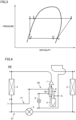
- FIG. 1 shows a configuration of a refrigeration cycle apparatus in a first embodiment.
- a refrigeration cycle apparatus 100 shown in Fig. 1 includes a refrigerant circuit C1 and a heating unit H1.
- Refrigerant circuit C1 includes, at least, a compressor 1, a first heat exchanger 2, a first decompressing apparatus 3, a second heat exchanger 4, and an accumulator 5. It should be noted that refrigerant circuit C1 may further include a four-way valve 10, although it is not essential. Further, in Figs. 4 , 6 , 8 , and 10 described later, refrigerant circuit C1 may also further include four-way valve 10, although it is not shown.
- Heating unit H1 includes a third heat exchanger 6.
- First heat exchanger 2 is configured to perform heat exchange between high-pressure refrigerant after having been compressed by compressor 1 and a heat medium such as the air.
- Second heat exchanger 4 is configured to perform heat exchange between low-pressure refrigerant decompressed by the first decompressing apparatus and the heat medium such as the air.
- Third heat exchanger 6 has a first flow path 6a and a second flow path 6b, and is configured to perform heat exchange between the refrigerant passing through first flow path 6a and the refrigerant passing through second flow path 6b.
- Compressor 1 is configured to change its operating frequency, in accordance with a control signal received from a controller not shown.
- compressor 1 includes therein a drive motor variable in rotational speed under inverter control and, when the operating frequency is changed, the rotational speed of the drive motor is changed. By changing the operating frequency of compressor 1, an output of compressor 1 is adjusted.
- Compressor 1 of any of various types such as rotary type, reciprocating type, scroll type, and screw type, for example, may be employed.
- Accumulator 5 is connected between compressor 1 and second heat exchanger 4 by pipes.
- First flow path 6a which is a low-pressure side flow path of third heat exchanger 6, is connected between compressor 1 and accumulator 5 by pipes.
- Second flow path 6b which is a high-pressure side flow path of third heat exchanger 6, is connected between first heat exchanger 2 and first decompressing apparatus 3 by pipes.
- the refrigeration cycle apparatus in the first embodiment is characterized in that heat is exchanged between the refrigerant passing through low-pressure side first flow path 6a and the refrigerant passing through high-pressure side second flow path 6b.
- the refrigerant circulates in order of compressor 1, first heat exchanger 2, first decompressing apparatus 3, second heat exchanger 4, and accumulator 5.
- Heating unit H1 is configured to heat the refrigerant that returns from accumulator 5 to compressor 1, using the refrigerant that has passed through first heat exchanger 2.
- Heating unit H1 includes third heat exchanger 6 configured to perform heat exchange between the refrigerant running toward first decompressing apparatus 3 after having passed through first heat exchanger 2 and the refrigerant running toward compressor 1 after having passed through accumulator 5.
- An “oil return ratio” refers to a ratio of the flow rate of an oil flowing from accumulator 5 to compressor 1, to the flow rate of the entire refrigerant. The lower the pressure loss in an oil return path due to an oil return hole in accumulator 5 or the like is, the higher the oil return ratio is, and reliability can be improved.
- the “degree of dryness” refers to a ratio of the flow rate of gas refrigerant flowing from the accumulator to the compressor, to the flow rate of the entire refrigerant flowing from the accumulator to the compressor (gas/(gas+liquid)). The higher the pressure loss in the oil return path due to the oil return hole or the like is, the lower the degree of dryness is, and liquid compression in compressor 1 can be suppressed and reliability can be improved.
- Fig. 2 shows the relation between each of the oil return ratio and the degree of dryness, and the pressure loss. As shown in Fig. 2 , the lower the pressure loss in the oil return path is, the higher the oil return ratio is, and the lower the pressure loss in the oil return path is, the higher the degree of dryness is. Thus, the oil return ratio and the degree of dryness have a trade-off relation.
- Fig. 3 is a p-h diagram for describing operation of the refrigeration cycle apparatus in the first embodiment.
- Points a to g in Fig. 3 correspond to states of the refrigerant at points a to g in Fig. 1 , respectively.
- the refrigerant discharged from compressor 1 (point a) passes through first heat exchanger 2 (point b), further passes through high-pressure side second flow path 6b of third heat exchanger 6 (point c), and is decompressed by first decompressing apparatus 3 (point d).
- the refrigerant thereafter passes through second heat exchanger 4 (point e), passes through accumulator 5 (point f), and then passes through low-pressure side first flow path 6a of third heat exchanger 6 (point g), and returns to compressor 1.
- Heat exchange is performed in low-pressure side first flow path 6a (points b to c) and high-pressure side second flow path 6b (points f to g) of third heat exchanger 6.
- third heat exchanger 6 is installed, which is configured to perform heat exchange between the high-temperature, high-pressure refrigerant and the low-temperature, low-pressure refrigerant between accumulator 5 and compressor 1.
- a branch flow path F1 configured to branch a part of the refrigerant having flowed out of high-pressure side first heat exchanger 2 and cause it to bypass first decompressing apparatus 3 is provided, and the third heat exchanger is arranged in branch flow path F1.
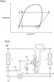
- FIG. 4 shows a configuration of a refrigeration cycle apparatus in the second embodiment.
- a refrigeration cycle apparatus 200 in the second embodiment includes refrigerant circuit C1 and a heating unit H2.
- Refrigerant circuit C1 includes, at least, compressor 1, first heat exchanger 2, first decompressing apparatus 3, second heat exchanger 4, and accumulator 5.
- Refrigeration cycle apparatus 200 further includes branch flow path F1 configured to branch from a branch portion 7 in a flow path running toward first decompressing apparatus 3 after having passed through first heat exchanger 2, and merge into refrigerant circuit C1 at a merge portion 8 downstream of branch portion 7 of refrigerant circuit C1, in refrigerant circuit C1.
- Heating unit H2 includes a second decompressing apparatus 9 configured to decompress the refrigerant flowing through branch flow path F1, and third heat exchanger 6 configured to perform heat exchange between the refrigerant flowing through branch flow path F1 and running from branch portion 7 toward second decompressing apparatus 9 and the refrigerant running toward compressor 1 after having passed through accumulator 5 in refrigerant circuit C1.
- first heat exchanger 2 second heat exchanger 4, first decompressing apparatus 3, and accumulator 5 are the same as those in the first embodiment, the description will not be repeated herein.
- Branch portion 7 is installed between first heat exchanger 2 and first decompressing apparatus 3 in refrigerant circuit C1.
- Merge portion 8 is arranged in a flow path running from second heat exchanger 4 toward accumulator 5 in refrigerant circuit C1.
- Second decompressing apparatus 9 is connected between branch portion 7 and merge portion 8 in branch flow path F1 by pipes.
- Low-pressure side first flow path 6a of third heat exchanger 6 is connected between accumulator 5 and compressor 1 in refrigerant circuit C1 by pipes.
- High-pressure side second flow path 6b of third heat exchanger 6 is connected between branch portion 7 and second decompressing apparatus 9 in branch flow path F1 by pipes.
- the refrigeration cycle apparatus is characterized in that heat is exchanged between the refrigerants in low-pressure side first flow path 6a and high-pressure side second flow path 6b.
- Fig. 5 is a p-h diagram for describing operation of the refrigeration cycle apparatus in the second embodiment. Points a to k in Fig. 5 correspond to states of the refrigerant at points a to k in Fig. 4 , respectively.
- first decompressing apparatus 3 (point d) flows in order of second heat exchanger 4 (point e) and merge portion 8, and the refrigerant having flowed out of high-pressure side second flow path 6b of third heat exchanger 6 (point j) passes through second decompressing apparatus 9 (point k).
- second decompressing apparatus 9 point k
- These refrigerants are merged at merge portion 8 (point f). Thereafter, the merged refrigerant passes through accumulator 5 (point g), and further passes through low-pressure side first flow path 6a of third heat exchanger 6 (point h).
- third heat exchanger 6 and second decompressing apparatus 9 are provided, third heat exchanger 6 being configured to perform heat exchange between the refrigerant flowing between accumulator 5 and compressor 1, and the refrigerant that is partially branched from the refrigerant having flowed out of high-pressure side first heat exchanger 2 and flows into branch flow path F1.
- the refrigerant in second flow path 6b subjected to heat exchange in third heat exchanger 6 is merged at merge portion 8 at an inlet of accumulator 5.
- the following effects are obtained.
- a branch flow path is also provided in a third embodiment, the position of merge portion 8 at which the refrigerant is merged is changed.
- the refrigerant having passed through the branch flow path is merged at an inlet part of low-pressure side second heat exchanger 4.
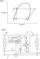
- FIG. 6 shows a configuration of a refrigeration cycle apparatus in the third embodiment.
- a refrigeration cycle apparatus 300 in the third embodiment includes refrigerant circuit C1 and a heating unit H3.
- Refrigerant circuit C1 includes, at least, compressor 1, first heat exchanger 2, first decompressing apparatus 3, second heat exchanger 4, and accumulator 5.
- Refrigeration cycle apparatus 300 further includes a branch flow path F2 configured to branch from branch portion 7 in the flow path running toward first decompressing apparatus 3 after having passed through first heat exchanger 2, and merge into refrigerant circuit C1 at a merge portion 82 downstream of branch portion 7 of refrigerant circuit C1, in refrigerant circuit C1.
- Merge portion 82 is arranged in a flow path running from first decompressing apparatus 3 toward second heat exchanger 4 in refrigerant circuit C1.
- Heating unit H3 includes second decompressing apparatus 9 configured to decompress the refrigerant flowing through branch flow path F2, and third heat exchanger 6.
- Third heat exchanger 6 is configured to perform heat exchange between the refrigerant flowing through branch flow path F2 and running from branch portion 7 toward second decompressing apparatus 9 and the refrigerant running toward compressor 1 after having passed through accumulator 5 in refrigerant circuit C1.
- first heat exchanger 2 second heat exchanger 4, first decompressing apparatus 3, and accumulator 5 are the same as those in the first embodiment, the description will not be repeated herein.
- Branch portion 7 is installed between first heat exchanger 2 and first decompressing apparatus 3 in refrigerant circuit C1.
- Merge portion 82 is installed between first decompressing apparatus 3 and second heat exchanger 4 in refrigerant circuit C1.
- Second decompressing apparatus 9 is connected between branch portion 7 and merge portion 82 in branch flow path F2 by pipes.
- Low-pressure side first flow path 6a of third heat exchanger 6 is connected between accumulator 5 and compressor 1 in refrigerant circuit C1 by pipes.
- High-pressure side second flow path 6b of third heat exchanger 6 is connected between branch portion 7 and second decompressing apparatus 9 in branch flow path F2 by pipes.
- the refrigeration cycle apparatus is characterized in that heat is exchanged between the refrigerants in low-pressure side first flow path 6a and high-pressure side second flow path 6b, as in the second embodiment.
- Fig. 7 is a p-h diagram for describing operation of the refrigeration cycle apparatus in the third embodiment. Points a to k in Fig. 7 correspond to states of the refrigerant at points a to k in Fig. 6 , respectively.
- the refrigerant merged at merge portion 82 passes through second heat exchanger 4 and accumulator 5 (points f, g), is subjected to heat exchange in low-pressure side first flow path 6a of third heat exchanger 6 (points g to h), and returns to compressor 1.
- third heat exchanger 6 is provided as in the second embodiment.
- the refrigerant having passed through the branch flow path subjected to heat exchange is merged at the inlet of second heat exchanger 4.
- a controller configured to control second decompressing apparatus 9 to have an appropriate opening degree is provided.
- FIG. 8 shows a configuration of a refrigeration cycle apparatus in the fourth embodiment.
- a refrigeration cycle apparatus 400 shown in Fig. 8 includes a sensor 50 and a controller 60, in addition to the components of refrigeration cycle apparatus 300 shown in Fig. 6 . Since other components are the same as those described in Fig. 6 , the description will not be repeated. It should be noted that sensor 50 and controller 60 may further be provided to refrigeration cycle apparatus 200 in Fig. 4 .
- Sensor 50 is a temperature sensor configured to sense the temperature of the refrigerant discharged from compressor 1, for example. It should be noted that sensor 50 may be any other sensor that can predict a suction state of compressor 1. Sensor 50 may be arranged on a suction side of compressor 1.
- Controller 60 has a configuration including a CPU (Central Processing Unit) 61, a memory 62 (a ROM (Read Only Memory) and a RAM (Random Access Memory)), input/output buffers (not shown), and the like.
- CPU 61 expands programs stored in the ROM onto the RAM or the like and executes the programs.
- the programs stored in the ROM are programs describing processing procedures of controller 60.
- controller 60 performs control of devices in refrigeration cycle apparatus 400. This control can be processed not only by software but also by dedicated hardware (electronic circuitry).
- controller 60 is configured to control second decompressing apparatus 9 in accordance with a value sensed by sensor 50.
- Fig. 9 is a flowchart for describing control performed by controller 60.
- controller 60 confirms an operation state of the refrigeration cycle apparatus.
- the refrigeration cycle apparatus is not operating (NO in S1), the processing of this flowchart ends.
- step S2 controller 60 obtains a sensed value from sensor 50.
- the sensed value is the temperature of the refrigerant discharged from compressor 1, for example.
- step S3 controller 60 compares the sensed value obtained from sensor 50 with a reference value.
- controller 60 decreases the opening degree of second decompressing apparatus 9 in step S4.
- controller 60 increases the opening degree of second decompressing apparatus 9 in step S5.
- step S4 or step S5 After the processing in step S4 or step S5, the processing from step S1 is performed again.
- second decompressing apparatus 9 is controlled to have an appropriate opening degree. Since the amount of heat exchange of third heat exchanger 6 is thereby controlled to an appropriate amount of heat exchange, the refrigeration cycle apparatus can be operated at a point excellent in performance, while suppressing an increase in the temperature of the refrigerant discharged from compressor 1.
- the refrigerant decompressed in a branch flow path is caused to exchange heat with the refrigerant running from an outlet of first heat exchanger 2 toward first decompressing apparatus 3, and merge into the refrigerant flowing through the refrigerant circuit at a merge point between compressor 1 and accumulator 5.
- FIG. 10 shows a configuration of a refrigeration cycle apparatus in the fifth embodiment.
- a refrigeration cycle apparatus 500 in the fifth embodiment includes refrigerant circuit C1 and a heating unit H4.
- Refrigerant circuit C1 includes, at least, compressor 1, first heat exchanger 2, first decompressing apparatus 3, second heat exchanger 4, and accumulator 5.
- first heat exchanger 2 second heat exchanger 4, first decompressing apparatus 3, and accumulator 5 are the same as those in the first to fourth embodiments, the description will not be repeated herein.
- Refrigeration cycle apparatus 500 further includes a branch flow path F3 configured to branch from branch portion 7 on the flow path running toward first decompressing apparatus 3 after having passed through first heat exchanger 2, and merge into refrigerant circuit C1 at a merge portion 83 on a flow path running toward compressor 1 after having passed through accumulator 5, in refrigerant circuit C1.
- Branch portion 7 is installed between first heat exchanger 2 and first decompressing apparatus 3 in refrigerant circuit C1.
- Merge portion 83 is installed between accumulator 5 and compressor 1 in refrigerant circuit C1.
- Heating unit H4 includes second decompressing apparatus 9 configured to decompress the refrigerant flowing through branch flow path F3, and third heat exchanger 6 configured to perform heat exchange between the refrigerant flowing through branch flow path F3 and running from second decompressing apparatus 9 toward merge portion 83 and the refrigerant running from branch portion 7 toward first decompressing apparatus 3 in refrigerant circuit C1.
- Second decompressing apparatus 9 is connected between branch portion 7 and merge portion 83 in branch flow path F3 by pipes. In this case, heating unit H4 heats the refrigerant to be suctioned by compressor 1, by causing the heated refrigerant to merge at the merge portion.
- Low-pressure side first flow path 6a of third heat exchanger 6 is connected between second decompressing apparatus 9 and merge portion 83 in branch flow path F3 by pipes.
- High-pressure side second flow path 6b of third heat exchanger 6 is connected between branch portion 7 and first decompressing apparatus 3 in refrigerant circuit C1 by pipes.
- the refrigeration cycle apparatus is characterized in that heat is exchanged between the refrigerants in low-pressure side first flow path 6a and high-pressure side second flow path 6b.
- Fig. 11 is a p-h diagram for describing operation of the refrigeration cycle apparatus in the fifth embodiment. Points a to k in Fig. 11 correspond to states of the refrigerant at points a to k in Fig. 10 , respectively.
- the refrigerant discharged from compressor 1 (point a) flows in order of first heat exchanger 2 and branch portion 7 (point b).
- one branched part runs toward high-pressure side second flow path 6b of third heat exchanger 6 (point c), and the other branched part flows into second decompressing apparatus 9 (point i).
- the refrigerant having passed through high-pressure side second flow path 6b of third heat exchanger 6 (point d) flows in order of first decompressing apparatus 3 (point e), second heat exchanger 4 (point f), accumulator 5 (point g), and merge portion 83.
- the refrigerant having passed through second decompressing apparatus 9 flows in order of low-pressure side first flow path 6a of third heat exchanger 6 (point k) and merge portion 83.
- the refrigerant merged at merge portion 83 (point h) is suctioned from a suction port of compressor 1.
- the refrigerant flows as described above, and heat exchange is performed between the refrigerant flowing through low-pressure side first flow path 6a and the refrigerant flowing through high-pressure side second flow path 6b of third heat exchanger 6.
- the refrigerant decompressed after having been branched into branch flow path F3 is caused to exchange heat with the refrigerant running from an outlet part of first heat exchanger 2 toward first decompressing apparatus 3, and then merge between compressor 1 and accumulator 5.
- Refrigeration cycle apparatus 100 includes: refrigerant circuit C1 including compressor 1, first heat exchanger 2, first decompressing apparatus 3, second heat exchanger 4, and accumulator 5; and heating unit H1.
- refrigerant circuit C1 refrigerant circulates in order of compressor 1, first heat exchanger 2, first decompressing apparatus 3, second heat exchanger 4, and accumulator 5.
- Heating unit H1 is configured to heat the refrigerant that returns from accumulator 5 to compressor 1, using the refrigerant that has passed through first heat exchanger 2.
- heating unit H1 includes third heat exchanger 6 configured to perform heat exchange between the refrigerant running toward first decompressing apparatus 3 after having passed through first heat exchanger 2 and the refrigerant running toward compressor 1 after having passed through accumulator 5.
- refrigeration cycle apparatus 200 or 300 further includes branch flow path F1 or F2 configured to branch from branch portion 7 in a flow path running toward first decompressing apparatus 3 after having passed through first heat exchanger 2, and merge into refrigerant circuit C1 at merge portion 8 or 82 downstream of branch portion 7 of refrigerant circuit C1, in refrigerant circuit C1.
- branch flow path F1 or F2 configured to branch from branch portion 7 in a flow path running toward first decompressing apparatus 3 after having passed through first heat exchanger 2, and merge into refrigerant circuit C1 at merge portion 8 or 82 downstream of branch portion 7 of refrigerant circuit C1, in refrigerant circuit C1.
- Heating unit H2 or H3 includes second decompressing apparatus 9 configured to decompress the refrigerant flowing through branch flow path F1 or F2, and third heat exchanger 6 configured to perform heat exchange between the refrigerant flowing through branch flow path F1 or F2 and running from branch portion 7 toward second decompressing apparatus 9 and the refrigerant running toward compressor 1 after having passed through accumulator 5 in refrigerant circuit C1.
- merge portion 8 is arranged in a flow path running from second heat exchanger 4 toward accumulator 5 in refrigerant circuit C1.
- merge portion 82 is arranged in a flow path running from first decompressing apparatus 3 toward second heat exchanger 4 in refrigerant circuit C 1.
- second decompressing apparatus 9 is an expansion valve configured to have a variable opening degree.
- Refrigeration cycle apparatus 400 further includes sensor 50 arranged on a suction side or a discharge side of compressor 1 and configured to sense a state of the refrigerant to be suctioned into compressor 1, and controller 60 configured to control the opening degree of second decompressing apparatus 9 in accordance with an output of sensor 50.
- sensor 50 is arranged on the discharge side of the compressor as shown in Fig. 8 in the present embodiment. However, the sensor may be arranged on the suction side of compressor 1.
- refrigeration cycle apparatus 500 further includes branch flow path F3 configured to branch from branch portion 7 on a flow path running toward first decompressing apparatus 3 after having passed through first heat exchanger 2, and merge into refrigerant circuit C1 at merge portion 83 on a flow path running toward compressor 1 after having passed through accumulator 5, in refrigerant circuit C1.
- Heating unit H4 includes second decompressing apparatus 9 configured to decompress the refrigerant flowing through branch flow path F3, and third heat exchanger 6 configured to perform heat exchange between the refrigerant flowing through branch flow path F3 and running from second decompressing apparatus 9 toward merge portion 83 and the refrigerant running from branch portion 7 toward first decompressing apparatus 3 in refrigerant circuit C1.
- heating unit H4 heats the refrigerant to be suctioned by compressor 1, by causing the heated refrigerant to merge at the merge portion.
Landscapes
- Engineering & Computer Science (AREA)
- Physics & Mathematics (AREA)
- Mechanical Engineering (AREA)
- Thermal Sciences (AREA)
- General Engineering & Computer Science (AREA)
- Compression-Type Refrigeration Machines With Reversible Cycles (AREA)
Abstract
Description
- The present disclosure relates to a refrigeration cycle apparatus.
-
Japanese Patent Laying-Open No. 2009-222348 - PTL 1:
Japanese Patent Laying-Open No. 2009-222348 - Within a compressor of a refrigeration cycle apparatus, there is a refrigerating machine oil in order to secure the lubricating property of the compressor. When the operation of the compressor is started, gas refrigerant is outputted from the compressor to a refrigerant circuit. With the flow of this gas refrigerant, a mixed liquid of liquid refrigerant and the refrigerating machine oil is taken out to the refrigerant circuit.
-
Japanese Patent Laying-Open No. 2009-222348 - However, when an accumulator is provided, liquid compression is suppressed, but oil return property from the accumulator is deteriorated, and the reliability of the compressor is reduced. Further, since surplus refrigerant stays in the accumulator, the degree of suction dryness of the compressor is decreased, and the performance of the compressor is deteriorated.
- An object of the present disclosure is to provide a refrigeration cycle apparatus that can avoid liquid compression using an accumulator and eliminate a shortage of a refrigerating machine oil in a compressor.
- The present disclosure relates to a refrigeration cycle apparatus. The refrigeration cycle apparatus includes: a refrigerant circuit including a compressor, a first heat exchanger, a first decompressing apparatus, a second heat exchanger, and an accumulator; and a heating unit. In the refrigerant circuit, refrigerant circulates in order of the compressor, the first heat exchanger, the first decompressing apparatus, the second heat exchanger, and the accumulator. The heating unit is configured to heat the refrigerant that returns from the accumulator to the compressor, using the refrigerant that has passed through the first heat exchanger.
- According to the refrigeration cycle apparatus in the present disclosure, it is possible to avoid liquid compression in the compressor and eliminate a shortage of a refrigerating machine oil in the compressor.
-
-
Fig. 1 shows a configuration of a refrigeration cycle apparatus in a first embodiment. -
Fig. 2 shows the relation between each of an oil return ratio and the degree of dryness, and pressure loss. -
Fig. 3 is a p-h diagram for describing operation of the refrigeration cycle apparatus in the first embodiment. -
Fig. 4 shows a configuration of a refrigeration cycle apparatus in a second embodiment. -
Fig. 5 is a p-h diagram for describing operation of the refrigeration cycle apparatus in the second embodiment. -
Fig. 6 shows a configuration of a refrigeration cycle apparatus in a third embodiment. -
Fig. 7 is a p-h diagram for describing operation of the refrigeration cycle apparatus in the third embodiment. -
Fig. 8 shows a configuration of a refrigeration cycle apparatus in a fourth embodiment. -
Fig. 9 is a flowchart for describing control performed by acontroller 60. -
Fig. 10 shows a configuration of a refrigeration cycle apparatus in a fifth embodiment. -
Fig. 11 is a p-h diagram for describing operation of the refrigeration cycle apparatus in the fifth embodiment. - Hereinafter, embodiments of the present disclosure will be described in detail with reference to the drawings. In the following, a plurality of embodiments will be described, and it is originally intended from the time of filing the present application to combine configurations described in the embodiments as appropriate. It should be noted that identical or corresponding parts in the drawings will be designated by the same reference characters, and the description thereof will not be repeated.
-
Fig. 1 shows a configuration of a refrigeration cycle apparatus in a first embodiment. Arefrigeration cycle apparatus 100 shown inFig. 1 includes a refrigerant circuit C1 and a heating unit H1. Refrigerant circuit C1 includes, at least, acompressor 1, afirst heat exchanger 2, a firstdecompressing apparatus 3, asecond heat exchanger 4, and anaccumulator 5. It should be noted that refrigerant circuit C1 may further include a four-way valve 10, although it is not essential. Further, inFigs. 4 ,6 ,8 , and10 described later, refrigerant circuit C1 may also further include four-way valve 10, although it is not shown. Heating unit H1 includes athird heat exchanger 6. -
First heat exchanger 2 is configured to perform heat exchange between high-pressure refrigerant after having been compressed bycompressor 1 and a heat medium such as the air.Second heat exchanger 4 is configured to perform heat exchange between low-pressure refrigerant decompressed by the first decompressing apparatus and the heat medium such as the air.Third heat exchanger 6 has afirst flow path 6a and asecond flow path 6b, and is configured to perform heat exchange between the refrigerant passing throughfirst flow path 6a and the refrigerant passing throughsecond flow path 6b. -
Compressor 1 is configured to change its operating frequency, in accordance with a control signal received from a controller not shown. Specifically,compressor 1 includes therein a drive motor variable in rotational speed under inverter control and, when the operating frequency is changed, the rotational speed of the drive motor is changed. By changing the operating frequency ofcompressor 1, an output ofcompressor 1 is adjusted.Compressor 1 of any of various types such as rotary type, reciprocating type, scroll type, and screw type, for example, may be employed. - Accumulator 5 is connected between
compressor 1 andsecond heat exchanger 4 by pipes.First flow path 6a, which is a low-pressure side flow path ofthird heat exchanger 6, is connected betweencompressor 1 andaccumulator 5 by pipes.Second flow path 6b, which is a high-pressure side flow path ofthird heat exchanger 6, is connected betweenfirst heat exchanger 2 and first decompressingapparatus 3 by pipes. - The refrigeration cycle apparatus in the first embodiment is characterized in that heat is exchanged between the refrigerant passing through low-pressure side
first flow path 6a and the refrigerant passing through high-pressure sidesecond flow path 6b. In refrigerant circuit C1, the refrigerant circulates in order ofcompressor 1,first heat exchanger 2, firstdecompressing apparatus 3,second heat exchanger 4, andaccumulator 5. Heating unit H1 is configured to heat the refrigerant that returns fromaccumulator 5 tocompressor 1, using the refrigerant that has passed throughfirst heat exchanger 2. Heating unit H1 includesthird heat exchanger 6 configured to perform heat exchange between the refrigerant running toward firstdecompressing apparatus 3 after having passed throughfirst heat exchanger 2 and the refrigerant running towardcompressor 1 after having passed throughaccumulator 5. - Here, before describing operation of
refrigeration cycle apparatus 100 in the first embodiment, definitions of several terms will be provided. - An "oil return ratio" refers to a ratio of the flow rate of an oil flowing from
accumulator 5 tocompressor 1, to the flow rate of the entire refrigerant. The lower the pressure loss in an oil return path due to an oil return hole inaccumulator 5 or the like is, the higher the oil return ratio is, and reliability can be improved. - The "degree of dryness" refers to a ratio of the flow rate of gas refrigerant flowing from the accumulator to the compressor, to the flow rate of the entire refrigerant flowing from the accumulator to the compressor (gas/(gas+liquid)). The higher the pressure loss in the oil return path due to the oil return hole or the like is, the lower the degree of dryness is, and liquid compression in
compressor 1 can be suppressed and reliability can be improved. -
Fig. 2 shows the relation between each of the oil return ratio and the degree of dryness, and the pressure loss. As shown inFig. 2 , the lower the pressure loss in the oil return path is, the higher the oil return ratio is, and the lower the pressure loss in the oil return path is, the higher the degree of dryness is. Thus, the oil return ratio and the degree of dryness have a trade-off relation. -
Fig. 3 is a p-h diagram for describing operation of the refrigeration cycle apparatus in the first embodiment. Points a to g inFig. 3 correspond to states of the refrigerant at points a to g inFig. 1 , respectively. The refrigerant discharged from compressor 1 (point a) passes through first heat exchanger 2 (point b), further passes through high-pressure side second flowpath 6b of third heat exchanger 6 (point c), and is decompressed by first decompressing apparatus 3 (point d). - Then, the refrigerant thereafter passes through second heat exchanger 4 (point e), passes through accumulator 5 (point f), and then passes through low-pressure side first flow
path 6a of third heat exchanger 6 (point g), and returns tocompressor 1. Heat exchange is performed in low-pressure side first flowpath 6a (points b to c) and high-pressure side second flowpath 6b (points f to g) ofthird heat exchanger 6. - As described above, in the refrigeration cycle apparatus in the first embodiment,
third heat exchanger 6 is installed, which is configured to perform heat exchange between the high-temperature, high-pressure refrigerant and the low-temperature, low-pressure refrigerant betweenaccumulator 5 andcompressor 1. - Thereby, the following effects are obtained. That is, even when the pressure loss in the oil return path due to the oil return hole in
accumulator 5 or the like is reduced to increase the oil return ratio and decrease the degree of dryness, only liquid compression can be suppressed bythird heat exchanger 6, and thus the reliability ofcompressor 1 can be improved while maintaining the performance of the refrigeration cycle apparatus. Further, heat transfer performance can be improved by decreasing the degree of dryness at an inlet and an outlet ofsecond heat exchanger 4. - In a second embodiment, a branch flow path F1 configured to branch a part of the refrigerant having flowed out of high-pressure side
first heat exchanger 2 and cause it to bypassfirst decompressing apparatus 3 is provided, and the third heat exchanger is arranged in branch flow path F1. -
Fig. 4 shows a configuration of a refrigeration cycle apparatus in the second embodiment. Arefrigeration cycle apparatus 200 in the second embodiment includes refrigerant circuit C1 and a heating unit H2. Refrigerant circuit C1 includes, at least,compressor 1,first heat exchanger 2,first decompressing apparatus 3,second heat exchanger 4, andaccumulator 5. -
Refrigeration cycle apparatus 200 further includes branch flow path F1 configured to branch from abranch portion 7 in a flow path running towardfirst decompressing apparatus 3 after having passed throughfirst heat exchanger 2, and merge into refrigerant circuit C1 at amerge portion 8 downstream ofbranch portion 7 of refrigerant circuit C1, in refrigerant circuit C1. Heating unit H2 includes asecond decompressing apparatus 9 configured to decompress the refrigerant flowing through branch flow path F1, andthird heat exchanger 6 configured to perform heat exchange between the refrigerant flowing through branch flow path F1 and running frombranch portion 7 towardsecond decompressing apparatus 9 and the refrigerant running towardcompressor 1 after having passed throughaccumulator 5 in refrigerant circuit C1. - Since
first heat exchanger 2,second heat exchanger 4,first decompressing apparatus 3, andaccumulator 5 are the same as those in the first embodiment, the description will not be repeated herein. -
Branch portion 7 is installed betweenfirst heat exchanger 2 andfirst decompressing apparatus 3 in refrigerant circuit C1. Mergeportion 8 is arranged in a flow path running fromsecond heat exchanger 4 towardaccumulator 5 in refrigerant circuit C1.Second decompressing apparatus 9 is connected betweenbranch portion 7 and mergeportion 8 in branch flow path F1 by pipes. - Low-pressure side first flow
path 6a ofthird heat exchanger 6 is connected betweenaccumulator 5 andcompressor 1 in refrigerant circuit C1 by pipes. High-pressure side second flowpath 6b ofthird heat exchanger 6 is connected betweenbranch portion 7 andsecond decompressing apparatus 9 in branch flow path F1 by pipes. - In the second embodiment, the refrigeration cycle apparatus is characterized in that heat is exchanged between the refrigerants in low-pressure side first flow
path 6a and high-pressure side second flowpath 6b. -
Fig. 5 is a p-h diagram for describing operation of the refrigeration cycle apparatus in the second embodiment. Points a to k inFig. 5 correspond to states of the refrigerant at points a to k inFig. 4 , respectively. - The refrigerant discharged from compressor 1 (point a) flows in order of first heat exchanger 2 (point b) and
branch portion 7. Of the refrigerant having flowed out ofbranch portion 7, one branched part passes through first decompressing apparatus 3 (point d), and the other branched part flows into high-pressure side second flowpath 6b ofthird heat exchanger 6 and is subjected to heat exchange (points i to j). The refrigerant having flowed out of first decompressing apparatus 3 (point d) flows in order of second heat exchanger 4 (point e) and mergeportion 8, and the refrigerant having flowed out of high-pressure side second flowpath 6b of third heat exchanger 6 (point j) passes through second decompressing apparatus 9 (point k). These refrigerants are merged at merge portion 8 (point f). Thereafter, the merged refrigerant passes through accumulator 5 (point g), and further passes through low-pressure side first flowpath 6a of third heat exchanger 6 (point h). - On this occasion, heat is exchanged between the refrigerant passing through low-pressure side first flow
path 6a (points g to h) and the refrigerant passing through high-pressure side second flowpath 6b (points i to j) ofthird heat exchanger 6. - As described above, in the second embodiment,
third heat exchanger 6 andsecond decompressing apparatus 9 are provided,third heat exchanger 6 being configured to perform heat exchange between the refrigerant flowing betweenaccumulator 5 andcompressor 1, and the refrigerant that is partially branched from the refrigerant having flowed out of high-pressure sidefirst heat exchanger 2 and flows into branch flow path F1. The refrigerant insecond flow path 6b subjected to heat exchange inthird heat exchanger 6 is merged atmerge portion 8 at an inlet ofaccumulator 5. - With such a configuration, the following effects are obtained. First, under a condition where the temperature of the refrigerant discharged from
compressor 1 increases, the temperature of the discharged refrigerant can be suppressed. Next, by reducing the flow rate of the refrigerant in low-pressure sidesecond heat exchanger 4, the pressure loss in refrigerant circuit C1 can be reduced, and the performance of the refrigeration cycle apparatus can be improved. - Although a branch flow path is also provided in a third embodiment, the position of
merge portion 8 at which the refrigerant is merged is changed. In the third embodiment, the refrigerant having passed through the branch flow path is merged at an inlet part of low-pressure sidesecond heat exchanger 4. -
Fig. 6 shows a configuration of a refrigeration cycle apparatus in the third embodiment. Arefrigeration cycle apparatus 300 in the third embodiment includes refrigerant circuit C1 and a heating unit H3. Refrigerant circuit C1 includes, at least,compressor 1,first heat exchanger 2,first decompressing apparatus 3,second heat exchanger 4, andaccumulator 5. -
Refrigeration cycle apparatus 300 further includes a branch flow path F2 configured to branch frombranch portion 7 in the flow path running towardfirst decompressing apparatus 3 after having passed throughfirst heat exchanger 2, and merge into refrigerant circuit C1 at amerge portion 82 downstream ofbranch portion 7 of refrigerant circuit C1, in refrigerant circuit C1. Mergeportion 82 is arranged in a flow path running from first decompressingapparatus 3 towardsecond heat exchanger 4 in refrigerant circuit C1. Heating unit H3 includessecond decompressing apparatus 9 configured to decompress the refrigerant flowing through branch flow path F2, andthird heat exchanger 6.Third heat exchanger 6 is configured to perform heat exchange between the refrigerant flowing through branch flow path F2 and running frombranch portion 7 towardsecond decompressing apparatus 9 and the refrigerant running towardcompressor 1 after having passed throughaccumulator 5 in refrigerant circuit C1. - Since
first heat exchanger 2,second heat exchanger 4,first decompressing apparatus 3, andaccumulator 5 are the same as those in the first embodiment, the description will not be repeated herein. -
Branch portion 7 is installed betweenfirst heat exchanger 2 andfirst decompressing apparatus 3 in refrigerant circuit C1. Mergeportion 82 is installed between first decompressingapparatus 3 andsecond heat exchanger 4 in refrigerant circuit C1.Second decompressing apparatus 9 is connected betweenbranch portion 7 and mergeportion 82 in branch flow path F2 by pipes. - Low-pressure side first flow
path 6a ofthird heat exchanger 6 is connected betweenaccumulator 5 andcompressor 1 in refrigerant circuit C1 by pipes. High-pressure side second flowpath 6b ofthird heat exchanger 6 is connected betweenbranch portion 7 andsecond decompressing apparatus 9 in branch flow path F2 by pipes. - In the third embodiment, the refrigeration cycle apparatus is characterized in that heat is exchanged between the refrigerants in low-pressure side first flow
path 6a and high-pressure side second flowpath 6b, as in the second embodiment. -
Fig. 7 is a p-h diagram for describing operation of the refrigeration cycle apparatus in the third embodiment. Points a to k inFig. 7 correspond to states of the refrigerant at points a to k inFig. 6 , respectively. - The refrigerant discharged from compressor 1 (point a) flows in order of first heat exchanger 2 (point b) and
branch portion 7. Of the refrigerant having flowed out ofbranch portion 7, one branched part passes through first decompressing apparatus 3 (point d), and the other branched part flows into high-pressure side second flowpath 6b ofthird heat exchanger 6 and is subjected to heat exchange (points i to j). The refrigerant having flowed out of first decompressing apparatus 3 (point d) reachesmerge portion 82. Further, the refrigerant having flowed out of high-pressure side second flowpath 6b ofthird heat exchanger 6 passes through second decompressing apparatus 9 (point k) and reaches mergeportion 82. The refrigerant merged at merge portion 82 (point e) passes throughsecond heat exchanger 4 and accumulator 5 (points f, g), is subjected to heat exchange in low-pressure side first flowpath 6a of third heat exchanger 6 (points g to h), and returns tocompressor 1. - On this occasion, heat is exchanged between the refrigerant passing through low-pressure side first flow
path 6a (points g to h) and the refrigerant passing through high-pressure side second flowpath 6b (points i to j) ofthird heat exchanger 6. - As described above, also in the third embodiment,
third heat exchanger 6 is provided as in the second embodiment. However, in the third embodiment, the refrigerant having passed through the branch flow path subjected to heat exchange is merged at the inlet ofsecond heat exchanger 4. - With such a configuration, the following effects are obtained in addition to the effects in the second embodiment. That is, by decreasing the degree of dryness at the inlet of low-pressure side
second heat exchanger 4, distribution performance can be improved, and the heat transfer performance of the refrigerant passing throughsecond heat exchanger 4 can be improved. - In a fourth embodiment, a controller configured to control
second decompressing apparatus 9 to have an appropriate opening degree is provided. -
Fig. 8 shows a configuration of a refrigeration cycle apparatus in the fourth embodiment. Arefrigeration cycle apparatus 400 shown inFig. 8 includes asensor 50 and acontroller 60, in addition to the components ofrefrigeration cycle apparatus 300 shown inFig. 6 . Since other components are the same as those described inFig. 6 , the description will not be repeated. It should be noted thatsensor 50 andcontroller 60 may further be provided torefrigeration cycle apparatus 200 inFig. 4 . -
Sensor 50 is a temperature sensor configured to sense the temperature of the refrigerant discharged fromcompressor 1, for example. It should be noted thatsensor 50 may be any other sensor that can predict a suction state ofcompressor 1.Sensor 50 may be arranged on a suction side ofcompressor 1. -
Controller 60 has a configuration including a CPU (Central Processing Unit) 61, a memory 62 (a ROM (Read Only Memory) and a RAM (Random Access Memory)), input/output buffers (not shown), and the like.CPU 61 expands programs stored in the ROM onto the RAM or the like and executes the programs. The programs stored in the ROM are programs describing processing procedures ofcontroller 60. In accordance with these programs,controller 60 performs control of devices inrefrigeration cycle apparatus 400. This control can be processed not only by software but also by dedicated hardware (electronic circuitry). In particular,controller 60 is configured to controlsecond decompressing apparatus 9 in accordance with a value sensed bysensor 50. -
Fig. 9 is a flowchart for describing control performed bycontroller 60. First, in step S1,controller 60 confirms an operation state of the refrigeration cycle apparatus. When the refrigeration cycle apparatus is not operating (NO in S1), the processing of this flowchart ends. - On the other hand, when the refrigeration cycle apparatus is operating (YES in S1), in step S2,
controller 60 obtains a sensed value fromsensor 50. The sensed value is the temperature of the refrigerant discharged fromcompressor 1, for example. Then, in step S3,controller 60 compares the sensed value obtained fromsensor 50 with a reference value. - In the case of the reference value < the sensed value (YES in S3),
controller 60 decreases the opening degree ofsecond decompressing apparatus 9 in step S4. On the other hand, in the case of the reference value > the sensed value (NO in S3),controller 60 increases the opening degree ofsecond decompressing apparatus 9 in step S5. - After the processing in step S4 or step S5, the processing from step S1 is performed again.
- As described above, in the fourth embodiment,
second decompressing apparatus 9 is controlled to have an appropriate opening degree. Since the amount of heat exchange ofthird heat exchanger 6 is thereby controlled to an appropriate amount of heat exchange, the refrigeration cycle apparatus can be operated at a point excellent in performance, while suppressing an increase in the temperature of the refrigerant discharged fromcompressor 1. - In a fifth embodiment, the refrigerant decompressed in a branch flow path is caused to exchange heat with the refrigerant running from an outlet of
first heat exchanger 2 towardfirst decompressing apparatus 3, and merge into the refrigerant flowing through the refrigerant circuit at a merge point betweencompressor 1 andaccumulator 5. -
Fig. 10 shows a configuration of a refrigeration cycle apparatus in the fifth embodiment. Arefrigeration cycle apparatus 500 in the fifth embodiment includes refrigerant circuit C1 and a heating unit H4. Refrigerant circuit C1 includes, at least,compressor 1,first heat exchanger 2,first decompressing apparatus 3,second heat exchanger 4, andaccumulator 5. - Since
first heat exchanger 2,second heat exchanger 4,first decompressing apparatus 3, andaccumulator 5 are the same as those in the first to fourth embodiments, the description will not be repeated herein. -
Refrigeration cycle apparatus 500 further includes a branch flow path F3 configured to branch frombranch portion 7 on the flow path running towardfirst decompressing apparatus 3 after having passed throughfirst heat exchanger 2, and merge into refrigerant circuit C1 at amerge portion 83 on a flow path running towardcompressor 1 after having passed throughaccumulator 5, in refrigerant circuit C1.Branch portion 7 is installed betweenfirst heat exchanger 2 andfirst decompressing apparatus 3 in refrigerant circuit C1. Mergeportion 83 is installed betweenaccumulator 5 andcompressor 1 in refrigerant circuit C1. - Heating unit H4 includes
second decompressing apparatus 9 configured to decompress the refrigerant flowing through branch flow path F3, andthird heat exchanger 6 configured to perform heat exchange between the refrigerant flowing through branch flow path F3 and running fromsecond decompressing apparatus 9 towardmerge portion 83 and the refrigerant running frombranch portion 7 towardfirst decompressing apparatus 3 in refrigerant circuit C1.Second decompressing apparatus 9 is connected betweenbranch portion 7 and mergeportion 83 in branch flow path F3 by pipes. In this case, heating unit H4 heats the refrigerant to be suctioned bycompressor 1, by causing the heated refrigerant to merge at the merge portion. - Low-pressure side first flow
path 6a ofthird heat exchanger 6 is connected between second decompressingapparatus 9 and mergeportion 83 in branch flow path F3 by pipes. High-pressure side second flowpath 6b ofthird heat exchanger 6 is connected betweenbranch portion 7 andfirst decompressing apparatus 3 in refrigerant circuit C1 by pipes. - In the fifth embodiment, the refrigeration cycle apparatus is characterized in that heat is exchanged between the refrigerants in low-pressure side first flow
path 6a and high-pressure side second flowpath 6b. -
Fig. 11 is a p-h diagram for describing operation of the refrigeration cycle apparatus in the fifth embodiment. Points a to k inFig. 11 correspond to states of the refrigerant at points a to k inFig. 10 , respectively. - In
Fig. 10 , the refrigerant discharged from compressor 1 (point a) flows in order offirst heat exchanger 2 and branch portion 7 (point b). Of the refrigerant branched atbranch portion 7, one branched part runs toward high-pressure side second flowpath 6b of third heat exchanger 6 (point c), and the other branched part flows into second decompressing apparatus 9 (point i). The refrigerant having passed through high-pressure side second flowpath 6b of third heat exchanger 6 (point d) flows in order of first decompressing apparatus 3 (point e), second heat exchanger 4 (point f), accumulator 5 (point g), and mergeportion 83. The refrigerant having passed through second decompressing apparatus 9 (point j) flows in order of low-pressure side first flowpath 6a of third heat exchanger 6 (point k) and mergeportion 83. The refrigerant merged at merge portion 83 (point h) is suctioned from a suction port ofcompressor 1. - The refrigerant flows as described above, and heat exchange is performed between the refrigerant flowing through low-pressure side first flow
path 6a and the refrigerant flowing through high-pressure side second flowpath 6b ofthird heat exchanger 6. - Thus, in the fifth embodiment, the refrigerant decompressed after having been branched into branch flow path F3 is caused to exchange heat with the refrigerant running from an outlet part of
first heat exchanger 2 towardfirst decompressing apparatus 3, and then merge betweencompressor 1 andaccumulator 5. Thereby, the following effects are obtained. - (1) Under the condition where the temperature of the refrigerant discharged from
compressor 1 increases, the temperature of the discharged refrigerant can be suppressed. - (2) By reducing the flow rate of the refrigerant in low-pressure side
second heat exchanger 4, pressure loss can be reduced, and the performance of the refrigeration cycle apparatus can be improved. - (3) By decreasing the degree of dryness of the refrigerant at the inlet of low-pressure side
second heat exchanger 4, distribution performance can be improved, and heat transfer performance can be improved. - Finally, the present embodiment will be summarized with reference to the drawings again.
- As shown in
Fig. 1 and the like, the present disclosure relates torefrigeration cycle apparatus 100.Refrigeration cycle apparatus 100 includes: refrigerant circuitC1 including compressor 1,first heat exchanger 2,first decompressing apparatus 3,second heat exchanger 4, andaccumulator 5; and heating unit H1. In refrigerant circuit C1, refrigerant circulates in order ofcompressor 1,first heat exchanger 2,first decompressing apparatus 3,second heat exchanger 4, andaccumulator 5. Heating unit H1 is configured to heat the refrigerant that returns fromaccumulator 5 tocompressor 1, using the refrigerant that has passed throughfirst heat exchanger 2. - Preferably, heating unit H1 includes
third heat exchanger 6 configured to perform heat exchange between the refrigerant running towardfirst decompressing apparatus 3 after having passed throughfirst heat exchanger 2 and the refrigerant running towardcompressor 1 after having passed throughaccumulator 5. - Preferably, as shown in
Fig. 4 orFig. 6 ,refrigeration cycle apparatus branch portion 7 in a flow path running towardfirst decompressing apparatus 3 after having passed throughfirst heat exchanger 2, and merge into refrigerant circuit C1 atmerge portion branch portion 7 of refrigerant circuit C1, in refrigerant circuit C1. Heating unit H2 or H3 includessecond decompressing apparatus 9 configured to decompress the refrigerant flowing through branch flow path F1 or F2, andthird heat exchanger 6 configured to perform heat exchange between the refrigerant flowing through branch flow path F1 or F2 and running frombranch portion 7 towardsecond decompressing apparatus 9 and the refrigerant running towardcompressor 1 after having passed throughaccumulator 5 in refrigerant circuit C1. - More preferably, as shown in
Fig. 4 , mergeportion 8 is arranged in a flow path running fromsecond heat exchanger 4 towardaccumulator 5 in refrigerant circuit C1. - More preferably, as shown in
Fig. 6 , mergeportion 82 is arranged in a flow path running from first decompressingapparatus 3 towardsecond heat exchanger 4 inrefrigerant circuit C 1. - More preferably, as shown in
Fig. 8 ,second decompressing apparatus 9 is an expansion valve configured to have a variable opening degree.Refrigeration cycle apparatus 400 further includessensor 50 arranged on a suction side or a discharge side ofcompressor 1 and configured to sense a state of the refrigerant to be suctioned intocompressor 1, andcontroller 60 configured to control the opening degree ofsecond decompressing apparatus 9 in accordance with an output ofsensor 50. It should be noted that, since the temperature of the refrigerant to be suctioned intocompressor 1 and the temperature of the refrigerant discharged from the compressor have a certain relation,sensor 50 is arranged on the discharge side of the compressor as shown inFig. 8 in the present embodiment. However, the sensor may be arranged on the suction side ofcompressor 1. - Preferably, as shown in
Fig. 10 ,refrigeration cycle apparatus 500 further includes branch flow path F3 configured to branch frombranch portion 7 on a flow path running towardfirst decompressing apparatus 3 after having passed throughfirst heat exchanger 2, and merge into refrigerant circuit C1 atmerge portion 83 on a flow path running towardcompressor 1 after having passed throughaccumulator 5, in refrigerant circuit C1. Heating unit H4 includessecond decompressing apparatus 9 configured to decompress the refrigerant flowing through branch flow path F3, andthird heat exchanger 6 configured to perform heat exchange between the refrigerant flowing through branch flow path F3 and running fromsecond decompressing apparatus 9 towardmerge portion 83 and the refrigerant running frombranch portion 7 towardfirst decompressing apparatus 3 in refrigerant circuit C1. In this case, heating unit H4 heats the refrigerant to be suctioned bycompressor 1, by causing the heated refrigerant to merge at the merge portion. - It should be understood that the embodiments disclosed herein are illustrative and non-restrictive in every respect. The scope of the present disclosure is defined by the scope of the claims, rather than the description of the embodiments described above, and is intended to include any modifications within the scope and meaning equivalent to the scope of the claims.
- 1: compressor; 2: first heat exchanger; 3: first decompressing apparatus; 4: second heat exchanger; 5: accumulator; 6: third heat exchanger; 6a: first flow path; 6b: second flow path; 7: branch portion; 10: four-way valve; 8, 82, 83: merge portion; 9: second decompressing apparatus; 50: sensor; 60: controller; 61: CPU; 62: memory; 100, 200, 300, 400, 500: refrigeration cycle apparatus; C1: refrigerant circuit; F1, F2, F3: flow path.
Claims (7)
- A refrigeration cycle apparatus, comprising:a refrigerant circuit including a compressor, a first heat exchanger, a first decompressing apparatus, a second heat exchanger, and an accumulator; anda heating unit, whereinin the refrigerant circuit, refrigerant circulates in order of the compressor, the first heat exchanger, the first decompressing apparatus, the second heat exchanger, and the accumulator, andthe heating unit is configured to heat the refrigerant that returns from the accumulator to the compressor, using the refrigerant that has passed through the first heat exchanger.
- The refrigeration cycle apparatus according to claim 1, wherein the heating unit includes a third heat exchanger configured to perform heat exchange between the refrigerant running toward the first decompressing apparatus after having passed through the first heat exchanger and the refrigerant running toward the compressor after having passed through the accumulator.
- The refrigeration cycle apparatus according to claim 1, further comprising a branch flow path configured to branch from a branch portion in a flow path running toward the first decompressing apparatus after having passed through the first heat exchanger, and merge into the refrigerant circuit at a merge portion downstream of the branch portion, in the refrigerant circuit, wherein
the heating unit includesa second decompressing apparatus configured to decompress the refrigerant flowing through the branch flow path, anda third heat exchanger configured to perform heat exchange between the refrigerant flowing through the branch flow path and running from the branch portion toward the second decompressing apparatus and the refrigerant running toward the compressor after having passed through the accumulator in the refrigerant circuit. - The refrigeration cycle apparatus according to claim 3, wherein the merge portion is arranged in a flow path running from the second heat exchanger toward the accumulator in the refrigerant circuit.
- The refrigeration cycle apparatus according to claim 3, wherein the merge portion is arranged in a flow path running from the first decompressing apparatus toward the second heat exchanger in the refrigerant circuit.
- The refrigeration cycle apparatus according to any one of claims 3 to 5, whereinthe second decompressing apparatus is an expansion valve configured to have a variable opening degree, andthe refrigeration cycle apparatus further comprisesa sensor arranged on a suction side or a discharge side of the compressor and configured to sense a state of the refrigerant, anda controller configured to control the opening degree of the second decompressing apparatus in accordance with an output of the sensor.
- The refrigeration cycle apparatus according to claim 1, further comprising a branch flow path configured to branch from a branch portion on a flow path running toward the first decompressing apparatus after having passed through the first heat exchanger, and merge into the refrigerant circuit at a merge portion on a flow path running toward the compressor after having passed through the accumulator, in the refrigerant circuit, wherein
the heating unit includesa second decompressing apparatus configured to decompress the refrigerant flowing through the branch flow path, anda third heat exchanger configured to perform heat exchange between the refrigerant flowing through the branch flow path and running from the second decompressing apparatus toward the merge portion and the refrigerant running from the branch portion toward the first decompressing apparatus in the refrigerant circuit.
Applications Claiming Priority (1)
| Application Number | Priority Date | Filing Date | Title |
|---|---|---|---|
| PCT/JP2021/047569 WO2023119482A1 (en) | 2021-12-22 | 2021-12-22 | Refrigeration cycle device |
Publications (2)
| Publication Number | Publication Date |
|---|---|
| EP4455576A1 true EP4455576A1 (en) | 2024-10-30 |
| EP4455576A4 EP4455576A4 (en) | 2025-01-15 |
Family
ID=86901700
Family Applications (1)
| Application Number | Title | Priority Date | Filing Date |
|---|---|---|---|
| EP21968919.7A Withdrawn EP4455576A4 (en) | 2021-12-22 | 2021-12-22 | Refrigeration cycle device |
Country Status (5)
| Country | Link |
|---|---|
| US (1) | US20250027694A1 (en) |
| EP (1) | EP4455576A4 (en) |
| JP (1) | JPWO2023119482A1 (en) |
| CN (1) | CN118511040A (en) |
| WO (1) | WO2023119482A1 (en) |
Family Cites Families (16)
| Publication number | Priority date | Publication date | Assignee | Title |
|---|---|---|---|---|
| JP2001330348A (en) * | 2000-05-25 | 2001-11-30 | Zexel Valeo Climate Control Corp | Automobile air-conditioning device using carbon dioxide |
| JP2002106985A (en) * | 2000-10-04 | 2002-04-10 | Matsushita Electric Ind Co Ltd | Air conditioning refrigeration equipment |
| JP4492017B2 (en) * | 2000-11-09 | 2010-06-30 | 株式会社デンソー | Accumulator module |
| JP2003130481A (en) * | 2001-10-24 | 2003-05-08 | Mitsubishi Heavy Ind Ltd | Vapor compression type refrigerating cycle of air conditioner for automobile |
| NO318864B1 (en) * | 2002-12-23 | 2005-05-18 | Sinvent As | Improved heat pump system |
| JP4160415B2 (en) * | 2003-02-13 | 2008-10-01 | カルソニックカンセイ株式会社 | Method of detecting frost formation in refrigeration cycle using supercritical refrigerant and defrosting method using the method |
| JP2006177632A (en) * | 2004-12-24 | 2006-07-06 | Denso Corp | Refrigeration cycle |
| KR20070038246A (en) * | 2005-10-05 | 2007-04-10 | 한라공조주식회사 | Automotive Heat Pump Systems |
| JP2008051474A (en) * | 2006-08-28 | 2008-03-06 | Denso Corp | Supercritical refrigeration cycle equipment |
| JP2008209059A (en) * | 2007-02-26 | 2008-09-11 | Denso Corp | Accumulator and vapor compression refrigeration cycle |
| JP2009222348A (en) | 2008-03-18 | 2009-10-01 | Daikin Ind Ltd | Refrigerating device |
| JP4931848B2 (en) * | 2008-03-31 | 2012-05-16 | 三菱電機株式会社 | Heat pump type outdoor unit for hot water supply |
| CN103958986B (en) * | 2011-11-29 | 2016-08-31 | 三菱电机株式会社 | Refrigerating air-conditioning |
| JP5949648B2 (en) * | 2013-04-18 | 2016-07-13 | 株式会社デンソー | Refrigeration cycle equipment |
| WO2015121992A1 (en) * | 2014-02-14 | 2015-08-20 | 三菱電機株式会社 | Refrigeration cycle device |
| CN115183507B (en) * | 2018-06-29 | 2025-05-13 | 三菱电机株式会社 | Refrigeration cycle device |
-
2021
- 2021-12-22 EP EP21968919.7A patent/EP4455576A4/en not_active Withdrawn
- 2021-12-22 WO PCT/JP2021/047569 patent/WO2023119482A1/en not_active Ceased
- 2021-12-22 CN CN202180105020.3A patent/CN118511040A/en not_active Withdrawn
- 2021-12-22 JP JP2023568876A patent/JPWO2023119482A1/ja not_active Withdrawn
- 2021-12-22 US US18/714,390 patent/US20250027694A1/en active Pending
Also Published As
| Publication number | Publication date |
|---|---|
| WO2023119482A1 (en) | 2023-06-29 |
| EP4455576A4 (en) | 2025-01-15 |
| JPWO2023119482A1 (en) | 2023-06-29 |
| CN118511040A (en) | 2024-08-16 |
| US20250027694A1 (en) | 2025-01-23 |
Similar Documents
| Publication | Publication Date | Title |
|---|---|---|
| EP2232169B1 (en) | Vapor compression system | |
| US8584487B2 (en) | Refrigerant system with expander speed control | |
| EP2126485B1 (en) | Refrigerant system and control method | |
| US9389005B2 (en) | Two-stage compression refrigeration cycle device | |
| EP2843323B1 (en) | Air conditioning device | |
| EP2863147A1 (en) | Air conditioning device | |
| CN101809378A (en) | Refrigerant system with bypass line and dedicated economized flow compression chamber | |
| EP3680565B1 (en) | Air conditioning device | |
| EP3954947B1 (en) | Outdoor unit, refrigeration cycle device, and refrigerating machine | |
| EP3425308B1 (en) | Air conditioning apparatus | |
| EP3199889A1 (en) | Air conditioner | |
| EP3425309B1 (en) | Air conditioning apparatus | |
| EP3936787B1 (en) | Refrigeration cycle device | |
| EP4030116B1 (en) | Outdoor unit and refrigeration cycle device | |
| EP3287714A1 (en) | Refrigeration cycle device | |
| WO2010017384A2 (en) | Improved operation of a refrigerant system | |
| EP4030117B1 (en) | Outdoor unit and refrigeration cycle device | |
| EP3546851A1 (en) | Refrigerating device | |
| EP4455576A1 (en) | Refrigeration cycle device | |
| GB2602893A (en) | Outdoor unit and refrigeration cycle device | |
| CN101336357A (en) | Refrigerant system discharge bypass into evaporator inlet | |
| EP4403848A1 (en) | Air conditioner | |
| EP3819556B1 (en) | Refrigeration cycle device and method for controlling same | |
| JP2021076260A (en) | Ejector type refrigeration device | |
| US12398934B2 (en) | Refrigeration cycle apparatus to attain both improvement in controllability for a flow rate of flowing gas refrigerant and improvement in heat exchange efficiency of a heat exchanger |
Legal Events
| Date | Code | Title | Description |
|---|---|---|---|
| STAA | Information on the status of an ep patent application or granted ep patent |
Free format text: STATUS: THE INTERNATIONAL PUBLICATION HAS BEEN MADE |
|
| PUAI | Public reference made under article 153(3) epc to a published international application that has entered the european phase |
Free format text: ORIGINAL CODE: 0009012 |
|
| STAA | Information on the status of an ep patent application or granted ep patent |
Free format text: STATUS: REQUEST FOR EXAMINATION WAS MADE |
|
| 17P | Request for examination filed |
Effective date: 20240611 |
|
| AK | Designated contracting states |
Kind code of ref document: A1 Designated state(s): AL AT BE BG CH CY CZ DE DK EE ES FI FR GB GR HR HU IE IS IT LI LT LU LV MC MK MT NL NO PL PT RO RS SE SI SK SM TR |
|
| A4 | Supplementary search report drawn up and despatched |
Effective date: 20241216 |
|
| RIC1 | Information provided on ipc code assigned before grant |
Ipc: F25B 1/00 20060101AFI20241210BHEP |
|
| STAA | Information on the status of an ep patent application or granted ep patent |
Free format text: STATUS: THE APPLICATION HAS BEEN WITHDRAWN |
|
| 18W | Application withdrawn |
Effective date: 20250212 |