EP4455560A1 - A gas-liquid separator for heat medium circulation system - Google Patents
A gas-liquid separator for heat medium circulation system Download PDFInfo
- Publication number
- EP4455560A1 EP4455560A1 EP23169623.8A EP23169623A EP4455560A1 EP 4455560 A1 EP4455560 A1 EP 4455560A1 EP 23169623 A EP23169623 A EP 23169623A EP 4455560 A1 EP4455560 A1 EP 4455560A1
- Authority
- EP
- European Patent Office
- Prior art keywords
- heat medium
- container
- heat exchanger
- main body
- container main
- Prior art date
- Legal status (The legal status is an assumption and is not a legal conclusion. Google has not performed a legal analysis and makes no representation as to the accuracy of the status listed.)
- Granted
Links
Images


Classifications
-
- F—MECHANICAL ENGINEERING; LIGHTING; HEATING; WEAPONS; BLASTING
- F24—HEATING; RANGES; VENTILATING
- F24H—FLUID HEATERS, e.g. WATER OR AIR HEATERS, HAVING HEAT-GENERATING MEANS, e.g. HEAT PUMPS, IN GENERAL
- F24H15/00—Control of fluid heaters
- F24H15/10—Control of fluid heaters characterised by the purpose of the control
- F24H15/12—Preventing or detecting fluid leakage
-
- F—MECHANICAL ENGINEERING; LIGHTING; HEATING; WEAPONS; BLASTING
- F24—HEATING; RANGES; VENTILATING
- F24D—DOMESTIC- OR SPACE-HEATING SYSTEMS, e.g. CENTRAL HEATING SYSTEMS; DOMESTIC HOT-WATER SUPPLY SYSTEMS; ELEMENTS OR COMPONENTS THEREFOR
- F24D19/00—Details
- F24D19/08—Arrangements for drainage, venting or aerating
- F24D19/082—Arrangements for drainage, venting or aerating for water heating systems
- F24D19/083—Venting arrangements
-
- F—MECHANICAL ENGINEERING; LIGHTING; HEATING; WEAPONS; BLASTING
- F24—HEATING; RANGES; VENTILATING
- F24H—FLUID HEATERS, e.g. WATER OR AIR HEATERS, HAVING HEAT-GENERATING MEANS, e.g. HEAT PUMPS, IN GENERAL
- F24H1/00—Water heaters, e.g. boilers, continuous-flow heaters or water-storage heaters
- F24H1/18—Water-storage heaters
- F24H1/20—Water-storage heaters with immersed heating elements, e.g. electric elements or furnace tubes
- F24H1/208—Water-storage heaters with immersed heating elements, e.g. electric elements or furnace tubes with tubes filled with heat transfer fluid
-
- F—MECHANICAL ENGINEERING; LIGHTING; HEATING; WEAPONS; BLASTING
- F28—HEAT EXCHANGE IN GENERAL
- F28D—HEAT-EXCHANGE APPARATUS, NOT PROVIDED FOR IN ANOTHER SUBCLASS, IN WHICH THE HEAT-EXCHANGE MEDIA DO NOT COME INTO DIRECT CONTACT
- F28D20/00—Heat storage plants or apparatus in general; Regenerative heat-exchange apparatus not covered by groups F28D17/00 or F28D19/00
- F28D20/0034—Heat storage plants or apparatus in general; Regenerative heat-exchange apparatus not covered by groups F28D17/00 or F28D19/00 using liquid heat storage material
-
- F—MECHANICAL ENGINEERING; LIGHTING; HEATING; WEAPONS; BLASTING
- F28—HEAT EXCHANGE IN GENERAL
- F28D—HEAT-EXCHANGE APPARATUS, NOT PROVIDED FOR IN ANOTHER SUBCLASS, IN WHICH THE HEAT-EXCHANGE MEDIA DO NOT COME INTO DIRECT CONTACT
- F28D7/00—Heat-exchange apparatus having stationary tubular conduit assemblies for both heat-exchange media, the media being in contact with different sides of a conduit wall
- F28D7/10—Heat-exchange apparatus having stationary tubular conduit assemblies for both heat-exchange media, the media being in contact with different sides of a conduit wall the conduits being arranged one within the other, e.g. concentrically
- F28D7/14—Heat-exchange apparatus having stationary tubular conduit assemblies for both heat-exchange media, the media being in contact with different sides of a conduit wall the conduits being arranged one within the other, e.g. concentrically both tubes being bent
-
- F—MECHANICAL ENGINEERING; LIGHTING; HEATING; WEAPONS; BLASTING
- F24—HEATING; RANGES; VENTILATING
- F24D—DOMESTIC- OR SPACE-HEATING SYSTEMS, e.g. CENTRAL HEATING SYSTEMS; DOMESTIC HOT-WATER SUPPLY SYSTEMS; ELEMENTS OR COMPONENTS THEREFOR
- F24D2200/00—Heat sources or energy sources
- F24D2200/12—Heat pump
-
- F—MECHANICAL ENGINEERING; LIGHTING; HEATING; WEAPONS; BLASTING
- F28—HEAT EXCHANGE IN GENERAL
- F28D—HEAT-EXCHANGE APPARATUS, NOT PROVIDED FOR IN ANOTHER SUBCLASS, IN WHICH THE HEAT-EXCHANGE MEDIA DO NOT COME INTO DIRECT CONTACT
- F28D1/00—Heat-exchange apparatus having stationary conduit assemblies for one heat-exchange medium only, the media being in contact with different sides of the conduit wall, in which the other heat-exchange medium is a large body of fluid, e.g. domestic or motor car radiators
- F28D1/02—Heat-exchange apparatus having stationary conduit assemblies for one heat-exchange medium only, the media being in contact with different sides of the conduit wall, in which the other heat-exchange medium is a large body of fluid, e.g. domestic or motor car radiators with heat-exchange conduits immersed in the body of fluid
- F28D1/0206—Heat exchangers immersed in a large body of liquid
- F28D1/0213—Heat exchangers immersed in a large body of liquid for heating or cooling a liquid in a tank
-
- F—MECHANICAL ENGINEERING; LIGHTING; HEATING; WEAPONS; BLASTING
- F28—HEAT EXCHANGE IN GENERAL
- F28D—HEAT-EXCHANGE APPARATUS, NOT PROVIDED FOR IN ANOTHER SUBCLASS, IN WHICH THE HEAT-EXCHANGE MEDIA DO NOT COME INTO DIRECT CONTACT
- F28D21/00—Heat-exchange apparatus not covered by any of the groups F28D1/00 - F28D20/00
- F28D2021/0019—Other heat exchangers for particular applications; Heat exchange systems not otherwise provided for
- F28D2021/0068—Other heat exchangers for particular applications; Heat exchange systems not otherwise provided for for refrigerant cycles
-
- F—MECHANICAL ENGINEERING; LIGHTING; HEATING; WEAPONS; BLASTING
- F28—HEAT EXCHANGE IN GENERAL
- F28D—HEAT-EXCHANGE APPARATUS, NOT PROVIDED FOR IN ANOTHER SUBCLASS, IN WHICH THE HEAT-EXCHANGE MEDIA DO NOT COME INTO DIRECT CONTACT
- F28D7/00—Heat-exchange apparatus having stationary tubular conduit assemblies for both heat-exchange media, the media being in contact with different sides of a conduit wall
- F28D7/02—Heat-exchange apparatus having stationary tubular conduit assemblies for both heat-exchange media, the media being in contact with different sides of a conduit wall the conduits being helically coiled
-
- F—MECHANICAL ENGINEERING; LIGHTING; HEATING; WEAPONS; BLASTING
- F28—HEAT EXCHANGE IN GENERAL
- F28F—DETAILS OF HEAT-EXCHANGE AND HEAT-TRANSFER APPARATUS, OF GENERAL APPLICATION
- F28F2265/00—Safety or protection arrangements; Arrangements for preventing malfunction
- F28F2265/12—Safety or protection arrangements; Arrangements for preventing malfunction for preventing overpressure
-
- F—MECHANICAL ENGINEERING; LIGHTING; HEATING; WEAPONS; BLASTING
- F28—HEAT EXCHANGE IN GENERAL
- F28F—DETAILS OF HEAT-EXCHANGE AND HEAT-TRANSFER APPARATUS, OF GENERAL APPLICATION
- F28F2265/00—Safety or protection arrangements; Arrangements for preventing malfunction
- F28F2265/16—Safety or protection arrangements; Arrangements for preventing malfunction for preventing leakage
-
- F—MECHANICAL ENGINEERING; LIGHTING; HEATING; WEAPONS; BLASTING
- F28—HEAT EXCHANGE IN GENERAL
- F28F—DETAILS OF HEAT-EXCHANGE AND HEAT-TRANSFER APPARATUS, OF GENERAL APPLICATION
- F28F2265/00—Safety or protection arrangements; Arrangements for preventing malfunction
- F28F2265/18—Safety or protection arrangements; Arrangements for preventing malfunction for removing contaminants, e.g. for degassing
Definitions
- the present invention relates to a heat medium storage device. More in particular, the invention relates to safety improvements to heat medium storage devices having heat exchanging elements.
- EP2080975A1 in the name of ATLANTIC CLIMATISATION ET VENT discloses a device for heat exchange between fluids belonging to two circuits.
- the device has a reservoir to receive coolant e.g. water, and a coolant inlet equipped at a lower part of the reservoir.
- a coolant outlet is equipped at an upper part of the reservoir.
- a coaxial heat pipe is arranged at inside of the reservoir, and is immersed in the coolant.
- An inner tube of the pipe is connected to the inlet at an end of the reservoir, and opens at another end of the reservoir.
- the inner tube is provided as a passage for the coolant.
- An outer tube of the pipe is provided as a passage for refrigerant.
- EP1965164A1 in name of ATLANTIC CLIMATISATION ET VENT discloses a device for heat exchange between fluids belonging to two circuits.
- the device has a reservoir to receive coolant fluid.
- the reservoir is equipped with a coolant fluid inlet arranged in a lower part of the reservoir and an outlet of a coolant fluid arranged in an upper part.
- An exchanger with coaxial tubes is arranged inside the reservoir, and is immersed in the fluid.
- An inner tube is connected to the inlet at an end, and is opened in the reservoir at another end.
- the tube has a section between the inlet and the exchanger, where the section is uncovered by an outer tube in which leakage opening is arranged.
- the present invention aims to resolve at least some of the problems and disadvantages mentioned above.
- the invention thereto aims to provide gas-liquid separator for a heat medium circulation system, said gas-liquid separator having improved gas-liquid separation which prevent the spreading of any leaked refrigerant to any user-side elements e.g., heat exchangers.
- the present invention thereof serve to provide a solution to one or more of above-mentioned disadvantages.
- the present invention relates to a gas-liquid separator for heat medium circulation system according to claim 1.
- the invention relates to a gas-liquid separator for heat medium circulation system comprising:
- the container is further provided with a container subpart at the upper part of the container main body and be in fluid communication with the internal space of the container main body.
- the container subpart has a width smaller than the width of the container main body, when the gas-liquid separator is viewed from above.
- the internal volume of the container subpart is up to 5% of the volume of the container. More preferably, the internal volume of the container subpart is up to 10%, 15%, 20%, most preferably, 25% of the volume of the container.
- Refrigerants used in heat pumps, air-conditioning or other similar refrigerant using installations have lower densities than water or other heat mediums with which said refrigerants are expected to exchange heat (e.g. mineral oil).
- the device of the present invention is particularly suited, though not exclusively, to the use of water as a heat medium.
- Water has a higher density than refrigerants, even when said refrigerants are compressed above normal operating pressures expected in heat pumps or air conditioning installations.
- the present invention takes advantage of the difference of density between refrigerant and heat medium, in particular the buoyancy effects produced by said difference. In this way, any refrigerant making its way to the inside of the container along with the heat medium via the first outlet will naturally have the tendency to separate from said heat medium and float upwards and pool over the heat medium.
- any leaked refrigerant will tend to pool and be retained inside the internal volume of said subpart.
- the refrigerant passage of the internal heat exchanger is part of a refrigerant circuit including at least one compressor for compressing said refrigerant.
- the container main body and the container subpart are formed with a cylindrical shape, wherein both of the cylindrical central axes are common.
- the cylindrical shape and its subpart, as well as their substantial concentricity advantageously allow for easier manufacturing. This configuration is particularly efficient in capturing any leaked refrigerant when the distal end of the heat medium of the heat exchanger is located near the axis of the container subpart.
- the container main body and the container subpart are formed with a cylindrical shape, wherein both of the cylindrical central axes are offset.
- the cylindrical shape and its subpart advantageously allow for easier manufacturing.
- This configuration is particularly efficient in capturing any leaked refrigerant when the distal end of the het medium of the heat exchanger is located near the central axis of the container subpart.
- the minimal distance between the distal end of the heat medium passage and the central axis of the container subpart is smaller than the minimal distance between the heat medium outlet and the central axis of the container subpart, when the gas-liquid separator is viewed from above.
- the heat medium outlet is located near a container wall and diametrically opposite to the container subpart. In this way, the heat medium outlet is advantageously distanced from any refrigerant coming from either the container subpart or the distal end of the heat medium passage of the heat exchanger, thereby eliminating the risk of refrigerant entering the heat medium outlet.
- the internal heat exchanger is a double tube heat exchanger with the heat medium passage in which the heat medium flows and the refrigerant passage in which the refrigerant flows defining the tubes of the double tube heat exchanger.
- the tubes of the double tube heat exchanger are substantially coaxial. In this way, the heat exchange between the refrigerant and the heat medium is advantageously made more uniform along the length of the heat exchanger.
- the inner tube of the heat exchanger is configured as a heat medium passage and the space between the inner and outer tube is configured as a refrigerant passage. In this way, both the heat medium inside the container and the heat medium inside the heat exchanger are, advantageously, able to simultaneously exchange heat with the refrigerant flowing through the refrigerant passage of the heat exchanger.
- the double tube heat exchanger is formed in a spiral or helical shape, wherein the central axis of the helix or spiral extends in the height direction of the gas-liquid separator.
- the heat exchanger advantageously has a larger heat exchange area, said heat exchange area being defined by both the inner and outer sides of the refrigerant passage.
- the larger heat exchange area permits more heat to be exchanged between the refrigerant and the heat medium before the refrigerant returns to the compressor side of the refrigerant circuit.
- the helical or spiral shape of the internal heat exchanger permits a more efficient use of the internal space of the container, advantageously allowing, for example, for smaller containers to be used.
- the distal end of the heat medium passage of the heat exchanger is located adjacent and is oriented tangential to a wall of the container main body.
- the spiral or helical shape of the heat exchanger includes at least two turns, the last of which turns includes the distal end of the heat medium passage of the heat exchanger, the distal end of the heat medium passage being located at least 10mm farther from the axis of the spiral or helix than each preceding turn.
- heat medium leaving the heat exchanger is advantageously ejected near the inner lateral walls of the container and in a direction that is substantially tangential to said walls.
- the heat medium outlet is located in substantial overlap with the cylindrical axis of the container main body.
- the heat medium outlet is shielded by the convection current around the inner and outer perimeter of the heat exchanger which force any leaked refrigerant upwards and away from said outlet. This advantageously makes it impossible for any refrigerant to leave the container via the heat medium outlet.
- the present invention concerns gas-liquid separator for a heat medium circulation system.
- the heat medium circulation system comprises of the gas-liquid separator, a pump, a controller that controls at least the pump and a usage-side heat exchanger like a radiator.
- the gas-liquid separator includes a container with an internal heat exchanger for exchanging heat between a heat medium and a refrigerant, the passages for each of these fluids being both inside the container and immersed in heat medium.
- the heat medium passage of the internal heat exchanger, the pump and the usage-side heat exchanger are connected by heat medium pipes, and the heat medium circulates inside the heat medium pipes.
- the refrigerant passage of the internal heat exchanger, an expansion valve, a heat source-side heat exchanger and a compressor are connected by refrigerant pipes, and the refrigerant circulates inside the refrigerant pipes.
- propane can be used as a refrigerant.
- R32 refrigerant can be also used.
- the heat medium passage includes a first outlet in fluid communication with the internal volume of the container.
- the container is provided with a container subpart connected to the top of said container.
- the internal volume of the container subpart is provided in fluid communication with the internal volume of the container.
- the location of the container subpart above the heat medium outlet allows for superior liquid gas separation, as any refrigerant leaking into the container quickly returns to a gaseous state and floats to the top of the internal volume of the container and into the internal volume of the container subpart.
- the smaller width of the container subpart in combination with the low buoyancy of the refrigerant contribute to trap the latter and prevent it from leaving the container to any user-side elements.
- the terms "one or more” or “at least one”, such as one or more or at least one member(s) of a group of members, is clear per se, by means of further exemplification, the term encompasses inter alia a reference to any one of said members, or to any two or more of said members, such as, e.g., any ⁇ 3, ⁇ 4, ⁇ 5, ⁇ 6 or ⁇ 7 etc. of said members, and up to all said members.
Landscapes
- Engineering & Computer Science (AREA)
- Physics & Mathematics (AREA)
- Thermal Sciences (AREA)
- Mechanical Engineering (AREA)
- General Engineering & Computer Science (AREA)
- Chemical & Material Sciences (AREA)
- Combustion & Propulsion (AREA)
- Heat-Exchange Devices With Radiators And Conduit Assemblies (AREA)
Abstract
Description
- The present invention relates to a heat medium storage device. More in particular, the invention relates to safety improvements to heat medium storage devices having heat exchanging elements.
-
EP2080975A1 in the name of ATLANTIC CLIMATISATION ET VENT , discloses a device for heat exchange between fluids belonging to two circuits. The device has a reservoir to receive coolant e.g. water, and a coolant inlet equipped at a lower part of the reservoir. A coolant outlet is equipped at an upper part of the reservoir. A coaxial heat pipe is arranged at inside of the reservoir, and is immersed in the coolant. An inner tube of the pipe is connected to the inlet at an end of the reservoir, and opens at another end of the reservoir. The inner tube is provided as a passage for the coolant. An outer tube of the pipe is provided as a passage for refrigerant. -
EP1965164A1 in name of ATLANTIC CLIMATISATION ET VENT , discloses a device for heat exchange between fluids belonging to two circuits. The device has a reservoir to receive coolant fluid. The reservoir is equipped with a coolant fluid inlet arranged in a lower part of the reservoir and an outlet of a coolant fluid arranged in an upper part. An exchanger with coaxial tubes is arranged inside the reservoir, and is immersed in the fluid. An inner tube is connected to the inlet at an end, and is opened in the reservoir at another end. The tube has a section between the inlet and the exchanger, where the section is uncovered by an outer tube in which leakage opening is arranged. - These known devices, like any other devices having refrigerant using heat exchanger are susceptible to develop refrigerant leakages. None of the devices disclosed in EP '975 nor in EP '164 include any leak remediation of prevention features. Furthermore, none of the disclosed devices include elements or features to prevent the passage of any leaked refrigerant to any user-side element.
- The present invention aims to resolve at least some of the problems and disadvantages mentioned above.
- The invention thereto aims to provide gas-liquid separator for a heat medium circulation system, said gas-liquid separator having improved gas-liquid separation which prevent the spreading of any leaked refrigerant to any user-side elements e.g., heat exchangers.
- The present invention thereof serve to provide a solution to one or more of above-mentioned disadvantages. To this end, the present invention relates to a gas-liquid separator for heat medium circulation system according to
claim 1. - In a first aspect, the invention relates to a gas-liquid separator for heat medium circulation system comprising:
- a container that comprises a container main body to receive and store the heat medium;
- a heat medium inlet that is located below the container main body and allows the heat medium to return from a usage-side heat exchanger to flow into the container main body;
- a heat medium outlet that is located in the upper half of above in the container main body and allows the heat medium to flow out of the container main body to the usage-side heat exchanger; and
- an internal heat exchanger having a heat medium passage and an adjoining refrigerant passage, said internal heat exchanger being immersed in the heat medium inside the container main body and permitting exchange of heat between a refrigerant flowing in the refrigerant passage and the heat medium flowing in the heat medium passage, a distal end of the heat medium passage opening into the space inside the container main body.
- The container is further provided with a container subpart at the upper part of the container main body and be in fluid communication with the internal space of the container main body. The container subpart has a width smaller than the width of the container main body, when the gas-liquid separator is viewed from above. By preference, the internal volume of the container subpart is up to 5% of the volume of the container. More preferably, the internal volume of the container subpart is up to 10%, 15%, 20%, most preferably, 25% of the volume of the container. Refrigerants used in heat pumps, air-conditioning or other similar refrigerant using installations have lower densities than water or other heat mediums with which said refrigerants are expected to exchange heat (e.g. mineral oil). The device of the present invention is particularly suited, though not exclusively, to the use of water as a heat medium. Water has a higher density than refrigerants, even when said refrigerants are compressed above normal operating pressures expected in heat pumps or air conditioning installations. The present invention takes advantage of the difference of density between refrigerant and heat medium, in particular the buoyancy effects produced by said difference. In this way, any refrigerant making its way to the inside of the container along with the heat medium via the first outlet will naturally have the tendency to separate from said heat medium and float upwards and pool over the heat medium. By having a container subpart on the top part of the container, any leaked refrigerant will tend to pool and be retained inside the internal volume of said subpart. In this way, the risk of any refrigerant flowing out of the container and into any usage-side heat exchanger is very nearly removed. By preference, the refrigerant passage of the internal heat exchanger is part of a refrigerant circuit including at least one compressor for compressing said refrigerant.
- In a further embodiment, the container main body and the container subpart are formed with a cylindrical shape, wherein both of the cylindrical central axes are common. The cylindrical shape and its subpart, as well as their substantial concentricity advantageously allow for easier manufacturing. This configuration is particularly efficient in capturing any leaked refrigerant when the distal end of the heat medium of the heat exchanger is located near the axis of the container subpart.
- In an embodiment, the container main body and the container subpart are formed with a cylindrical shape, wherein both of the cylindrical central axes are offset. The cylindrical shape and its subpart, advantageously allow for easier manufacturing. This configuration is particularly efficient in capturing any leaked refrigerant when the distal end of the het medium of the heat exchanger is located near the central axis of the container subpart. By preference, the minimal distance between the distal end of the heat medium passage and the central axis of the container subpart is smaller than the minimal distance between the heat medium outlet and the central axis of the container subpart, when the gas-liquid separator is viewed from above. More preferably, the heat medium outlet is located near a container wall and diametrically opposite to the container subpart. In this way, the heat medium outlet is advantageously distanced from any refrigerant coming from either the container subpart or the distal end of the heat medium passage of the heat exchanger, thereby eliminating the risk of refrigerant entering the heat medium outlet.
- In an embodiment, the internal heat exchanger is a double tube heat exchanger with the heat medium passage in which the heat medium flows and the refrigerant passage in which the refrigerant flows defining the tubes of the double tube heat exchanger. By preference, the tubes of the double tube heat exchanger are substantially coaxial. In this way, the heat exchange between the refrigerant and the heat medium is advantageously made more uniform along the length of the heat exchanger. By preference, the inner tube of the heat exchanger is configured as a heat medium passage and the space between the inner and outer tube is configured as a refrigerant passage. In this way, both the heat medium inside the container and the heat medium inside the heat exchanger are, advantageously, able to simultaneously exchange heat with the refrigerant flowing through the refrigerant passage of the heat exchanger.
- In an embodiment, the double tube heat exchanger is formed in a spiral or helical shape, wherein the central axis of the helix or spiral extends in the height direction of the gas-liquid separator. In this way the heat exchanger advantageously has a larger heat exchange area, said heat exchange area being defined by both the inner and outer sides of the refrigerant passage. The larger heat exchange area permits more heat to be exchanged between the refrigerant and the heat medium before the refrigerant returns to the compressor side of the refrigerant circuit. Furthermore, the helical or spiral shape of the internal heat exchanger permits a more efficient use of the internal space of the container, advantageously allowing, for example, for smaller containers to be used.
- In an embodiment, the distal end of the heat medium passage of the heat exchanger is located adjacent and is oriented tangential to a wall of the container main body. By preference, the spiral or helical shape of the heat exchanger includes at least two turns, the last of which turns includes the distal end of the heat medium passage of the heat exchanger, the distal end of the heat medium passage being located at least 10mm farther from the axis of the spiral or helix than each preceding turn. In this way, heat medium leaving the heat exchanger is advantageously ejected near the inner lateral walls of the container and in a direction that is substantially tangential to said walls. By locating the distal end of the heat medium passage of the heat exchanger farther from the axis of the spiral or helical heat exchanger, a gap between all but part of the last coil of heat exchanger and the inner walls of the container is left. By virtue of the contact of the heat medium in the container and the outer tube of the spiral or helical heat exchanger, convection currents are created around the heat exchanger. These convection currents, advantageously push the heat medium introduced via distal end of the heat medium passage of the heat exchanger upwards and along the inner walls of the container. In this way, the rise of any leaked refrigerant to the internal volume of the container subpart and away from the heat medium outlet is advantageously accelerated. By preference, the heat medium outlet is located in substantial overlap with the cylindrical axis of the container main body. In this way, the heat medium outlet is shielded by the convection current around the inner and outer perimeter of the heat exchanger which force any leaked refrigerant upwards and away from said outlet. This advantageously makes it impossible for any refrigerant to leave the container via the heat medium outlet.
- The following description of the figures of specific embodiments of the invention is merely exemplary in nature and is not intended to limit the present teachings, their application or uses. Throughout the drawings, corresponding reference numerals indicate like or corresponding parts and features.
-
Figure 1 shows a section view of the gas-liquid separator equipped with a heat medium outlet port on the side. -
Figure 2 shows a section view of the gas-liquid separator equipped with a heat medium outlet port on the side. -
Figure 3 shows a double tube heat exchanger having an extended first outlet. -
Figure 4 shows a top section view of the gas-liquid separator equipped with the double tube heat exchanger having an extended first outlet. - The invention is further described by the following non-limiting examples which further illustrate the invention, and are not intended to, nor should they be interpreted to, limit the scope of the invention.
- The present invention concerns gas-liquid separator for a heat medium circulation system. The heat medium circulation system comprises of the gas-liquid separator, a pump, a controller that controls at least the pump and a usage-side heat exchanger like a radiator. The gas-liquid separator includes a container with an internal heat exchanger for exchanging heat between a heat medium and a refrigerant, the passages for each of these fluids being both inside the container and immersed in heat medium. The heat medium passage of the internal heat exchanger, the pump and the usage-side heat exchanger are connected by heat medium pipes, and the heat medium circulates inside the heat medium pipes. The refrigerant passage of the internal heat exchanger, an expansion valve, a heat source-side heat exchanger and a compressor are connected by refrigerant pipes, and the refrigerant circulates inside the refrigerant pipes. In this embodiment, propane can be used as a refrigerant. Also, R32 refrigerant can be also used. The heat medium passage includes a first outlet in fluid communication with the internal volume of the container. The container is provided with a container subpart connected to the top of said container. The internal volume of the container subpart is provided in fluid communication with the internal volume of the container. The location of the container subpart above the heat medium outlet allows for superior liquid gas separation, as any refrigerant leaking into the container quickly returns to a gaseous state and floats to the top of the internal volume of the container and into the internal volume of the container subpart. The smaller width of the container subpart in combination with the low buoyancy of the refrigerant contribute to trap the latter and prevent it from leaving the container to any user-side elements.
- Unless otherwise defined, all terms used in disclosing the invention, including technical and scientific terms, have the meaning as commonly understood by one of ordinary skill in the art to which this invention belongs. By means of further guidance, term definitions are included to better appreciate the teaching of the present invention.
- As used herein, the following terms have the following meanings:
- "A", "an", and "the" as used herein refers to both singular and plural referents unless the context clearly dictates otherwise. By way of example, "a compartment" refers to one or more than one compartment.
- "Comprise", "comprising", and "comprises" and "comprised of" as used herein are synonymous with "include", "including", "includes" or "contain", "containing", "contains" and are inclusive or open-ended terms that specifies the presence of what follows e.g. component and do not exclude or preclude the presence of additional, non-recited components, features, element, members, steps, known in the art or disclosed therein.
- Furthermore, the terms first, second, third and the like in the description and in the claims, are used for distinguishing between similar elements and not necessarily for describing a sequential or chronological order, unless specified. It is to be understood that the terms so used are interchangeable under appropriate circumstances and that the embodiments of the invention described herein are capable of operation in other sequences than described or illustrated herein.
- The recitation of numerical ranges by endpoints includes all numbers and fractions subsumed within that range, as well as the recited endpoints.
- Whereas the terms "one or more" or "at least one", such as one or more or at least one member(s) of a group of members, is clear per se, by means of further exemplification, the term encompasses inter alia a reference to any one of said members, or to any two or more of said members, such as, e.g., any ≥3, ≥4, ≥5, ≥6 or ≥7 etc. of said members, and up to all said members.
- Unless otherwise defined, all terms used in disclosing the invention, including technical and scientific terms, have the meaning as commonly understood by one of ordinary skill in the art to which this invention belongs. By means of further guidance, definitions for the terms used in the description are included to better appreciate the teaching of the present invention. The terms or definitions used herein are provided solely to aid in the understanding of the invention.
- Reference throughout this specification to "one embodiment" or "an embodiment" means that a particular feature, structure or characteristic described in connection with the embodiment is included in at least one embodiment of the present invention. Thus, appearances of the phrases "in one embodiment" or "in an embodiment" in various places throughout this specification are not necessarily all referring to the same embodiment, but may. Furthermore, the particular features, structures or characteristics may be combined in any suitable manner, as would be apparent to a person skilled in the art from this disclosure, in one or more embodiments. Furthermore, while some embodiments described herein include some but not other features included in other embodiments, combinations of features of different embodiments are meant to be within the scope of the invention, and form different embodiments, as would be understood by those in the art. For example, in the following claims, any of the claimed embodiments can be used in any combination.
- With as a goal illustrating better the properties of the invention the following presents, as an example and limiting in no way other potential applications, a description of a number of embodiments of the gas-liquid separator based on the invention, wherein:
-
FIG.1 shows a section view of the gas-liquid separator (1) equipped with a heat medium outlet port (10) on the side. The gas-liquid separator (1) includes a container (2), which container encloses a double tube heat exchanger (3). The tubes of the double tube heat exchanger (3) are coaxial. Also the container (2) comprises a container main body (17) and a container subpart (16)at the upper part of the container main body (17) and be in fluid communication with the internal space of the container main body. The container main body (17) and the container subpart (16) are formed with a cylindrical shape, wherein both of the cylindrical central axes are common. The figure shows the heat exchanger (3) having an inner tube (12) placed inside an outer tube (13). The inner tube (12) defines a heat medium passage (5), while the space between the inner tube (12) and the outer tube (13) defines a refrigerant passage (6). A refrigerant inlet tube (14) near the proximal end of the heat exchanger (3), and refrigerant outlet tube (15) located near the distal end of the heat exchanger (3) provide fluid connection with a refrigerant circuit (not shown). An outlet tube (11) is shown disposed to the lateral wall of the container (2). The outlet tube (11) provides fluid connection between a heat medium outlet (4) on the inside of the container (2) and a heat medium outlet port (10). The figure, shows the heat medium outlet (4) placed at a height lower than that of a first outlet (9) (equivalent to the "distal end of the heat medium passage" as used in this document, for instance in the claims) of the heat exchanger. But, the heat medium outlet (4) may be placed at a height higher than that of the first outlet (9) of the heat exchanger. The figure shows the trajectory of any leaked refrigerant in a gaseous state (19) leaked through the first outlet (9). An over-pressure valve (18) is shown on top of the container (2), said over-pressure valve (16) being in fluid communication with the inside of the container (2). The valve (18) is configured to open automatically if the pressure inside the container (2) exceeds a predetermined safety threshold (e.g. 60% of the failure pressure of the container). The valve (18) may be a mechanical or an electro-mechanical valve, preferably a solenoid valve assembly equipped with a pressure indicator and a controller. The pressure indicator being configured to send a signal with information related to the pressure inside the container (2) to the controller, and the controller being configured to compare the signal received from the pressure indicator with a pre-set safety pressure. The controller is configured to send a signal to the solenoid valve if the pressure inside the container (2) exceeds said pre-set safety pressure, the signal containing instructions to cause the solenoid valve to open and to control the aperture of said valve. -
FIG. 2 shows a section view of the gas-liquid separator (1) equipped with the heat medium outlet port (10) on the bottom. The gas-liquid separator (1) includes a container (2), which container encloses a double tube heat exchanger (3) and includes a container subpart (16) in substantial alignment with the axial direction of the container (2). The figure shows the heat exchanger (3) having an inner tube (12) placed inside an outer tube (13). The inner tube (12) defines a heat medium passage (5), while the space between the inner tube (12) and the outer tube (13) defines a refrigerant passage (6). The inner tube (12) and the outer tube (13) are coaxial. A refrigerant inlet tube (14) near the proximal end of the heat exchanger (3), and refrigerant outlet tube (15) located near the distal end of the heat exchanger (3) provide fluid connection with a refrigerant circuit (not shown). A first inlet (7) of the heat exchanger (3) is shown extending out of the container (2), in this way enabling the ingress of heat medium to the heat medium passage (5) of the heat exchanger (3) and into the container (2) via the first outlet (9) of the heat exchanger. An outlet tube (11) is shown disposed to the bottom wall of the container (2) and oriented in substantial alignment with the axis of the container (2). The outlet tube (11) provides fluid connection between a heat medium outlet (4) on the inside of the container (2) and a heat medium outlet port (10), said heat medium outlet (4) having a larger diameter than the heat medium outlet port (10). The figure shows the heat medium outlet (4) placed at a height lower than that of the first outlet of the heat exchanger (3). But the heat medium outlet (4) may be placed at a height higher than that of the first outlet (9) of the heat exchanger. The figure shows the trajectory of any leaked refrigerant in a gaseous state (19) leaked through the first outlet (9). An over-pressure valve (18) is shown on top of the container (2), said over-pressure valve (16) being in fluid communication with the inside of the container (2). The valve (18) is configured to open automatically if the pressure inside the container (2) exceeds a predetermined safety threshold (e.g., 60% of the failure pressure of the container). The valve (18) may be a mechanical or an electro-mechanical valve, preferably a solenoid valve assembly equipped with a pressure indicator and a controller. The pressure indicator being configured to send a signal with information related to the pressure inside the container (2) to the controller, and the controller being configured to compare the signal received from the pressure indicator with a pre-set safety pressure. The controller is configured to send a signal to the solenoid valve if the pressure inside the container (2) exceeds said pre-set safety pressure, the signal containing instructions to cause the solenoid valve to open and to control the aperture of said valve. -
FIG. 3 shows a double tube heat exchanger (3) having an extended first outlet (9). The shown heat exchanger (3) shares an almost identical construction to those of the embodiments shown inFIG. 1-2 , differing only in the longer first outlet (9). The features of this embodiment of the heat exchanger (3) are better appreciated inFIG. 4 . -
FIG. 4 shows a top section view of the gas-liquid separator (1) equipped with the double tube heat exchanger (3) having an extended first outlet (9). The figure shows the distal end of the first outlet (9) converging towards the wall of the container (2) and away from the axis of the heat exchanger (3) until the axis of the extended first outlet (9) is tangential with the walls of the container (2). The figure shows the container main body (17) and the container subpart (16) are formed with a cylindrical shape, wherein both of the cylindrical central axes are common. The figure shows the heat medium outlet (4) is located in substantial overlap with the cylindrical axis of the container main body (17). -
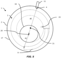
FIG. 5 shows a top section view of the gas-liquid separator (1) equipped with the double tube heat exchanger (3) having an extended first outlet (9). The figure shows the distal end of the first outlet (9) converging towards the wall of the container (2) and away from the axis of the heat exchanger (3) until the axis of the extended first outlet (9) is tangential with the walls of the container (2). The figure shows the container main body (17) and the container subpart (16) are formed with a cylindrical shape, wherein both of the cylindrical central axes (20, 21) are offset. The figure shows the heat medium outlet (4) is located laterally on the container main body (17). The minimal distance (d1) between the distal end of the first outlet (9) and the central axis of the container subpart (20) is smaller than the minimal distance (d2) between the heat medium outlet (4) and the central axis of the container subpart (20). -
- 1
- gas-liquid separator
- 2
- container
- 3
- double tube heat-exchanger
- 4
- heat medium outlet
- 5
- heat medium passage
- 6
- refrigerant passage
- 7
- first inlet
- 8
- heat medium inlet
- 9
- first outlet
- 10
- heat medium outlet port
- 11
- outlet tube
- 12
- inner tube
- 13
- outer tube
- 14
- refrigerant inlet tube
- 15
- refrigerant outlet tube
- 16
- container subpart
- 17
- container main body
- 18
- over-pressure valve
- 19
- trajectory of refrigerant gas leaking from the first outlet
- 20
- axis of container subpart
- 21
- axis of container main body
- d1
- distance between the central axis of the container subpart and the distal end of the first outlet
- d2
- distance between the central axis of the container subpart and the heat medium outlet
- The present invention is in no way limited to the embodiments shown in the figures. On the contrary, methods according to the present invention may be realized in many different ways without departing from the scope of the invention.
Claims (10)
- A gas-liquid separator for heat medium circulation system comprising;a container that comprises a container main body to receive and store the heat medium;a heat medium inlet that is located below the container main body and allows the heat medium to return from a usage-side heat exchanger to flow into the container main body;a heat medium outlet that is located in the upper half of the container main body and allows the heat medium to flow out of the container main body to the usage-side heat exchanger; andan internal heat exchanger having a heat medium passage and an adjoining refrigerant passage, said internal heat exchanger being immersed in the heat medium inside the container main body and permitting exchange of heat between a refrigerant flowing in the refrigerant passage and the heat medium flowing in the heat medium passage, a distal end of the heat medium passage opening inside the container main body;characterized in that, the container comprises a container subpart at the upper side of the container main body, and in fluid communication with the internal space of the container main body, wherein the container subpart has a width smaller than the width of the container main body.
- The device according to claim 1, characterized in that, the container main body and the container subpart are formed with a cylindrical shape, wherein both of the cylindrical central axes are common.
- The device according to claim 1, characterized in that, the container main body and the container subpart are formed with a cylindrical shape, wherein both of the cylindrical central axes are offset.
- The device according to claim 3, characterized in that, the minimal distance between the distal end of the heat medium passage and the central axis of the container subpart is smaller than the minimal distance between the heat medium outlet and the central axis of the container subpart.
- The device according to any one of the claims 1-4, characterized in that, the internal heat exchanger is a double tube heat exchanger with the heat medium passage in which the heat medium flows and the refrigerant passage in which the refrigerant flows defining the tubes of the double tube heat exchanger.
- The device according to claim 5, characterized in that, the tubes of the double tube heat exchanger are coaxial.
- The device according to any one of the claims 5-6, characterized in that, the double tube heat exchanger is formed in a spiral or helical shape, wherein the central axis of the spiral or helical extends in the height direction of the gas-liquid separator.
- The device according to any of the previous claims 5-7, characterized in that, the distal end of the heat medium passage of the heat exchanger is located adjacent and is oriented tangential to a wall of the container main body.
- The device according to any of the claim 7 or 8, characterized in that, the spiral or helical shape of the heat exchanger includes at least two turns, the last of which turns includes the distal end of the heat medium passage of the heat exchanger, the distal end of the heat medium passage being located at least 10mm farther from the axis of the spiral or helix than each preceding turn.
- The device according to any of the preceding claims 5-7, characterized in that, the heat medium outlet is located in overlap with the cylindrical axis of the container main body.
Priority Applications (1)
| Application Number | Priority Date | Filing Date | Title |
|---|---|---|---|
| EP23169623.8A EP4455560B1 (en) | 2023-04-24 | 2023-04-24 | A gas-liquid separator for heat medium circulation system |
Applications Claiming Priority (1)
| Application Number | Priority Date | Filing Date | Title |
|---|---|---|---|
| EP23169623.8A EP4455560B1 (en) | 2023-04-24 | 2023-04-24 | A gas-liquid separator for heat medium circulation system |
Publications (2)
| Publication Number | Publication Date |
|---|---|
| EP4455560A1 true EP4455560A1 (en) | 2024-10-30 |
| EP4455560B1 EP4455560B1 (en) | 2025-10-01 |
Family
ID=86226675
Family Applications (1)
| Application Number | Title | Priority Date | Filing Date |
|---|---|---|---|
| EP23169623.8A Active EP4455560B1 (en) | 2023-04-24 | 2023-04-24 | A gas-liquid separator for heat medium circulation system |
Country Status (1)
| Country | Link |
|---|---|
| EP (1) | EP4455560B1 (en) |
Citations (3)
| Publication number | Priority date | Publication date | Assignee | Title |
|---|---|---|---|---|
| US20030196450A1 (en) * | 2002-03-18 | 2003-10-23 | Sadao Higami | Refrigerant processing apparatus for collected equipment, and oil separator |
| EP1965164A1 (en) | 2007-02-28 | 2008-09-03 | Atlantic Climatisation et Ventilation | Device for heat exchange between fluids belonging to two circuits |
| EP2080975A1 (en) | 2008-01-16 | 2009-07-22 | Atlantic Climatisation et Ventilation | Device for heat exchange between fluids belonging to two circuits. |
-
2023
- 2023-04-24 EP EP23169623.8A patent/EP4455560B1/en active Active
Patent Citations (3)
| Publication number | Priority date | Publication date | Assignee | Title |
|---|---|---|---|---|
| US20030196450A1 (en) * | 2002-03-18 | 2003-10-23 | Sadao Higami | Refrigerant processing apparatus for collected equipment, and oil separator |
| EP1965164A1 (en) | 2007-02-28 | 2008-09-03 | Atlantic Climatisation et Ventilation | Device for heat exchange between fluids belonging to two circuits |
| EP2080975A1 (en) | 2008-01-16 | 2009-07-22 | Atlantic Climatisation et Ventilation | Device for heat exchange between fluids belonging to two circuits. |
Also Published As
| Publication number | Publication date |
|---|---|
| EP4455560B1 (en) | 2025-10-01 |
Similar Documents
| Publication | Publication Date | Title |
|---|---|---|
| JP4687710B2 (en) | Refrigeration equipment | |
| KR101297958B1 (en) | Strainers for air conditioning device | |
| CN107489786B (en) | Slidingtype switching valve and refrigerating circulation system | |
| JP2011202876A (en) | Centrifugal oil separator and outdoor unit of air conditioning device | |
| US20080041093A1 (en) | Accumulator of air conditioner | |
| EP1961597A1 (en) | Air-conditioning system for vehicles | |
| JP3416963B2 (en) | Gas-liquid separator | |
| MXPA04007013A (en) | Multi-pass parallel-tubes heat exchanger. | |
| ES2345372T3 (en) | HEAT EXCHANGE DEVICE BETWEEN FLUIDS BELONGING TO TWO CIRCUITS. | |
| JP2008196762A (en) | Shunt, heat exchanger unit, and refrigeration system | |
| CN110195948A (en) | Gas-liquid separator and heat-exchange system | |
| KR20070004340A (en) | Piping type filter and air conditioner with same | |
| EP4455560B1 (en) | A gas-liquid separator for heat medium circulation system | |
| EP4455598A1 (en) | A gas-liquid separator for heat medium circulation system | |
| EP3086070B1 (en) | Subcooler and air conditioner including the same | |
| JP6631489B2 (en) | Heat exchanger | |
| EP4455559B1 (en) | Gas-liquid separator for a heat medium circulation system | |
| AU2006293190A1 (en) | Air conditioning apparatus | |
| JP7025868B2 (en) | Refrigerant system with direct contact heat exchanger | |
| JP4387974B2 (en) | Refrigeration cycle equipment | |
| CN212157751U (en) | Gas-liquid separator and air conditioning system | |
| CN110953773A (en) | Flash evaporator and refrigerating system | |
| CN212300027U (en) | Heat exchanger and air conditioning system | |
| JP2008069993A (en) | Heat exchanger and heat pump water heater using the same | |
| JP2002277079A (en) | Refrigeration cycle |
Legal Events
| Date | Code | Title | Description |
|---|---|---|---|
| PUAI | Public reference made under article 153(3) epc to a published international application that has entered the european phase |
Free format text: ORIGINAL CODE: 0009012 |
|
| STAA | Information on the status of an ep patent application or granted ep patent |
Free format text: STATUS: THE APPLICATION HAS BEEN PUBLISHED |
|
| AK | Designated contracting states |
Kind code of ref document: A1 Designated state(s): AL AT BE BG CH CY CZ DE DK EE ES FI FR GB GR HR HU IE IS IT LI LT LU LV MC ME MK MT NL NO PL PT RO RS SE SI SK SM TR |
|
| STAA | Information on the status of an ep patent application or granted ep patent |
Free format text: STATUS: REQUEST FOR EXAMINATION WAS MADE |
|
| 17P | Request for examination filed |
Effective date: 20241227 |
|
| GRAP | Despatch of communication of intention to grant a patent |
Free format text: ORIGINAL CODE: EPIDOSNIGR1 |
|
| STAA | Information on the status of an ep patent application or granted ep patent |
Free format text: STATUS: GRANT OF PATENT IS INTENDED |
|
| INTG | Intention to grant announced |
Effective date: 20250305 |
|
| GRAJ | Information related to disapproval of communication of intention to grant by the applicant or resumption of examination proceedings by the epo deleted |
Free format text: ORIGINAL CODE: EPIDOSDIGR1 |
|
| STAA | Information on the status of an ep patent application or granted ep patent |
Free format text: STATUS: REQUEST FOR EXAMINATION WAS MADE |
|
| GRAP | Despatch of communication of intention to grant a patent |
Free format text: ORIGINAL CODE: EPIDOSNIGR1 |
|
| STAA | Information on the status of an ep patent application or granted ep patent |
Free format text: STATUS: GRANT OF PATENT IS INTENDED |
|
| INTC | Intention to grant announced (deleted) | ||
| INTG | Intention to grant announced |
Effective date: 20250528 |
|
| GRAS | Grant fee paid |
Free format text: ORIGINAL CODE: EPIDOSNIGR3 |
|
| GRAA | (expected) grant |
Free format text: ORIGINAL CODE: 0009210 |
|
| STAA | Information on the status of an ep patent application or granted ep patent |
Free format text: STATUS: THE PATENT HAS BEEN GRANTED |
|
| AK | Designated contracting states |
Kind code of ref document: B1 Designated state(s): AL AT BE BG CH CY CZ DE DK EE ES FI FR GB GR HR HU IE IS IT LI LT LU LV MC ME MK MT NL NO PL PT RO RS SE SI SK SM TR |
|
| REG | Reference to a national code |
Ref country code: GB Ref legal event code: FG4D Ref country code: CH Ref legal event code: F10 Free format text: ST27 STATUS EVENT CODE: U-0-0-F10-F00 (AS PROVIDED BY THE NATIONAL OFFICE) Effective date: 20251001 |
|
| REG | Reference to a national code |
Ref country code: DE Ref legal event code: R096 Ref document number: 602023007040 Country of ref document: DE |
|
| REG | Reference to a national code |
Ref country code: IE Ref legal event code: FG4D |
|
| P01 | Opt-out of the competence of the unified patent court (upc) registered |
Free format text: CASE NUMBER: UPC_APP_8708_4455560/2025 Effective date: 20251002 |
|
| REG | Reference to a national code |
Ref country code: NL Ref legal event code: MP Effective date: 20251001 |
|
| REG | Reference to a national code |
Ref country code: AT Ref legal event code: MK05 Ref document number: 1842821 Country of ref document: AT Kind code of ref document: T Effective date: 20251001 |
|
| PG25 | Lapsed in a contracting state [announced via postgrant information from national office to epo] |
Ref country code: NL Free format text: LAPSE BECAUSE OF FAILURE TO SUBMIT A TRANSLATION OF THE DESCRIPTION OR TO PAY THE FEE WITHIN THE PRESCRIBED TIME-LIMIT Effective date: 20251001 |
|
| PG25 | Lapsed in a contracting state [announced via postgrant information from national office to epo] |
Ref country code: ES Free format text: LAPSE BECAUSE OF FAILURE TO SUBMIT A TRANSLATION OF THE DESCRIPTION OR TO PAY THE FEE WITHIN THE PRESCRIBED TIME-LIMIT Effective date: 20251001 |
|
| REG | Reference to a national code |
Ref country code: LT Ref legal event code: MG9D |
|
| PG25 | Lapsed in a contracting state [announced via postgrant information from national office to epo] |
Ref country code: NO Free format text: LAPSE BECAUSE OF FAILURE TO SUBMIT A TRANSLATION OF THE DESCRIPTION OR TO PAY THE FEE WITHIN THE PRESCRIBED TIME-LIMIT Effective date: 20260101 |
|
| PG25 | Lapsed in a contracting state [announced via postgrant information from national office to epo] |
Ref country code: AT Free format text: LAPSE BECAUSE OF FAILURE TO SUBMIT A TRANSLATION OF THE DESCRIPTION OR TO PAY THE FEE WITHIN THE PRESCRIBED TIME-LIMIT Effective date: 20251001 Ref country code: HR Free format text: LAPSE BECAUSE OF FAILURE TO SUBMIT A TRANSLATION OF THE DESCRIPTION OR TO PAY THE FEE WITHIN THE PRESCRIBED TIME-LIMIT Effective date: 20251001 Ref country code: FI Free format text: LAPSE BECAUSE OF FAILURE TO SUBMIT A TRANSLATION OF THE DESCRIPTION OR TO PAY THE FEE WITHIN THE PRESCRIBED TIME-LIMIT Effective date: 20251001 |
|
| PG25 | Lapsed in a contracting state [announced via postgrant information from national office to epo] |
Ref country code: RS Free format text: LAPSE BECAUSE OF FAILURE TO SUBMIT A TRANSLATION OF THE DESCRIPTION OR TO PAY THE FEE WITHIN THE PRESCRIBED TIME-LIMIT Effective date: 20260101 |
|
| PG25 | Lapsed in a contracting state [announced via postgrant information from national office to epo] |
Ref country code: IS Free format text: LAPSE BECAUSE OF FAILURE TO SUBMIT A TRANSLATION OF THE DESCRIPTION OR TO PAY THE FEE WITHIN THE PRESCRIBED TIME-LIMIT Effective date: 20260201 |
|
| PG25 | Lapsed in a contracting state [announced via postgrant information from national office to epo] |
Ref country code: PT Free format text: LAPSE BECAUSE OF FAILURE TO SUBMIT A TRANSLATION OF THE DESCRIPTION OR TO PAY THE FEE WITHIN THE PRESCRIBED TIME-LIMIT Effective date: 20260202 Ref country code: CZ Free format text: LAPSE BECAUSE OF FAILURE TO SUBMIT A TRANSLATION OF THE DESCRIPTION OR TO PAY THE FEE WITHIN THE PRESCRIBED TIME-LIMIT Effective date: 20251001 |
|
| PG25 | Lapsed in a contracting state [announced via postgrant information from national office to epo] |
Ref country code: PL Free format text: LAPSE BECAUSE OF FAILURE TO SUBMIT A TRANSLATION OF THE DESCRIPTION OR TO PAY THE FEE WITHIN THE PRESCRIBED TIME-LIMIT Effective date: 20251001 |
|
| PG25 | Lapsed in a contracting state [announced via postgrant information from national office to epo] |
Ref country code: LV Free format text: LAPSE BECAUSE OF FAILURE TO SUBMIT A TRANSLATION OF THE DESCRIPTION OR TO PAY THE FEE WITHIN THE PRESCRIBED TIME-LIMIT Effective date: 20251001 |
|
| PG25 | Lapsed in a contracting state [announced via postgrant information from national office to epo] |
Ref country code: BG Free format text: LAPSE BECAUSE OF FAILURE TO SUBMIT A TRANSLATION OF THE DESCRIPTION OR TO PAY THE FEE WITHIN THE PRESCRIBED TIME-LIMIT Effective date: 20251001 |
|
| PG25 | Lapsed in a contracting state [announced via postgrant information from national office to epo] |
Ref country code: LT Free format text: LAPSE BECAUSE OF FAILURE TO SUBMIT A TRANSLATION OF THE DESCRIPTION OR TO PAY THE FEE WITHIN THE PRESCRIBED TIME-LIMIT Effective date: 20251001 |
|
| REG | Reference to a national code |
Ref country code: DE Ref legal event code: R097 Ref document number: 602023007040 Country of ref document: DE |
|
| PG25 | Lapsed in a contracting state [announced via postgrant information from national office to epo] |
Ref country code: SM Free format text: LAPSE BECAUSE OF FAILURE TO SUBMIT A TRANSLATION OF THE DESCRIPTION OR TO PAY THE FEE WITHIN THE PRESCRIBED TIME-LIMIT Effective date: 20251001 |
|
| PG25 | Lapsed in a contracting state [announced via postgrant information from national office to epo] |
Ref country code: DK Free format text: LAPSE BECAUSE OF FAILURE TO SUBMIT A TRANSLATION OF THE DESCRIPTION OR TO PAY THE FEE WITHIN THE PRESCRIBED TIME-LIMIT Effective date: 20251001 |
|
| PG25 | Lapsed in a contracting state [announced via postgrant information from national office to epo] |
Ref country code: IT Free format text: LAPSE BECAUSE OF FAILURE TO SUBMIT A TRANSLATION OF THE DESCRIPTION OR TO PAY THE FEE WITHIN THE PRESCRIBED TIME-LIMIT Effective date: 20251001 |
|
| PGFP | Annual fee paid to national office [announced via postgrant information from national office to epo] |
Ref country code: DE Payment date: 20260522 Year of fee payment: 4 |
|
| PG25 | Lapsed in a contracting state [announced via postgrant information from national office to epo] |
Ref country code: EE Free format text: LAPSE BECAUSE OF FAILURE TO SUBMIT A TRANSLATION OF THE DESCRIPTION OR TO PAY THE FEE WITHIN THE PRESCRIBED TIME-LIMIT Effective date: 20251001 |
|
| PGFP | Annual fee paid to national office [announced via postgrant information from national office to epo] |
Ref country code: FR Payment date: 20260526 Year of fee payment: 4 |
|
| PG25 | Lapsed in a contracting state [announced via postgrant information from national office to epo] |
Ref country code: SK Free format text: LAPSE BECAUSE OF FAILURE TO SUBMIT A TRANSLATION OF THE DESCRIPTION OR TO PAY THE FEE WITHIN THE PRESCRIBED TIME-LIMIT Effective date: 20251001 |
|
| PG25 | Lapsed in a contracting state [announced via postgrant information from national office to epo] |
Ref country code: SE Free format text: LAPSE BECAUSE OF FAILURE TO SUBMIT A TRANSLATION OF THE DESCRIPTION OR TO PAY THE FEE WITHIN THE PRESCRIBED TIME-LIMIT Effective date: 20251001 |
|
| PLBE | No opposition filed within time limit |
Free format text: ORIGINAL CODE: 0009261 |
|
| STAA | Information on the status of an ep patent application or granted ep patent |
Free format text: STATUS: NO OPPOSITION FILED WITHIN TIME LIMIT |
|
| REG | Reference to a national code |
Ref country code: CH Ref legal event code: L10 Free format text: ST27 STATUS EVENT CODE: U-0-0-L10-L00 (AS PROVIDED BY THE NATIONAL OFFICE) Effective date: 20260812 |