EP4455535A1 - Druckbehälter mit kleinem durchmesser und langer achse - Google Patents
Druckbehälter mit kleinem durchmesser und langer achse Download PDFInfo
- Publication number
- EP4455535A1 EP4455535A1 EP22911613.2A EP22911613A EP4455535A1 EP 4455535 A1 EP4455535 A1 EP 4455535A1 EP 22911613 A EP22911613 A EP 22911613A EP 4455535 A1 EP4455535 A1 EP 4455535A1
- Authority
- EP
- European Patent Office
- Prior art keywords
- pressure vessel
- winding
- metal boss
- liner
- angle
- Prior art date
- Legal status (The legal status is an assumption and is not a legal conclusion. Google has not performed a legal analysis and makes no representation as to the accuracy of the status listed.)
- Pending
Links
Images


Classifications
-
- F—MECHANICAL ENGINEERING; LIGHTING; HEATING; WEAPONS; BLASTING
- F17—STORING OR DISTRIBUTING GASES OR LIQUIDS
- F17C—VESSELS FOR CONTAINING OR STORING COMPRESSED, LIQUEFIED OR SOLIDIFIED GASES; FIXED-CAPACITY GAS-HOLDERS; FILLING VESSELS WITH, OR DISCHARGING FROM VESSELS, COMPRESSED, LIQUEFIED, OR SOLIDIFIED GASES
- F17C1/00—Pressure vessels, e.g. gas cylinder, gas tank, replaceable cartridge
-
- F—MECHANICAL ENGINEERING; LIGHTING; HEATING; WEAPONS; BLASTING
- F17—STORING OR DISTRIBUTING GASES OR LIQUIDS
- F17C—VESSELS FOR CONTAINING OR STORING COMPRESSED, LIQUEFIED OR SOLIDIFIED GASES; FIXED-CAPACITY GAS-HOLDERS; FILLING VESSELS WITH, OR DISCHARGING FROM VESSELS, COMPRESSED, LIQUEFIED, OR SOLIDIFIED GASES
- F17C1/00—Pressure vessels, e.g. gas cylinder, gas tank, replaceable cartridge
- F17C1/02—Pressure vessels, e.g. gas cylinder, gas tank, replaceable cartridge involving reinforcing arrangements
- F17C1/04—Protecting sheathings
- F17C1/06—Protecting sheathings built-up from wound-on bands or filamentary material, e.g. wires
-
- F—MECHANICAL ENGINEERING; LIGHTING; HEATING; WEAPONS; BLASTING
- F17—STORING OR DISTRIBUTING GASES OR LIQUIDS
- F17C—VESSELS FOR CONTAINING OR STORING COMPRESSED, LIQUEFIED OR SOLIDIFIED GASES; FIXED-CAPACITY GAS-HOLDERS; FILLING VESSELS WITH, OR DISCHARGING FROM VESSELS, COMPRESSED, LIQUEFIED, OR SOLIDIFIED GASES
- F17C13/00—Details of vessels or of the filling or discharging of vessels
- F17C13/002—Details of vessels or of the filling or discharging of vessels for vessels under pressure
-
- F—MECHANICAL ENGINEERING; LIGHTING; HEATING; WEAPONS; BLASTING
- F17—STORING OR DISTRIBUTING GASES OR LIQUIDS
- F17C—VESSELS FOR CONTAINING OR STORING COMPRESSED, LIQUEFIED OR SOLIDIFIED GASES; FIXED-CAPACITY GAS-HOLDERS; FILLING VESSELS WITH, OR DISCHARGING FROM VESSELS, COMPRESSED, LIQUEFIED, OR SOLIDIFIED GASES
- F17C2201/00—Vessel construction, in particular geometry, arrangement or size
- F17C2201/01—Shape
- F17C2201/0104—Shape cylindrical
- F17C2201/0109—Shape cylindrical with exteriorly curved end-piece
-
- F—MECHANICAL ENGINEERING; LIGHTING; HEATING; WEAPONS; BLASTING
- F17—STORING OR DISTRIBUTING GASES OR LIQUIDS
- F17C—VESSELS FOR CONTAINING OR STORING COMPRESSED, LIQUEFIED OR SOLIDIFIED GASES; FIXED-CAPACITY GAS-HOLDERS; FILLING VESSELS WITH, OR DISCHARGING FROM VESSELS, COMPRESSED, LIQUEFIED, OR SOLIDIFIED GASES
- F17C2201/00—Vessel construction, in particular geometry, arrangement or size
- F17C2201/05—Size
- F17C2201/056—Small (<1 m3)
-
- F—MECHANICAL ENGINEERING; LIGHTING; HEATING; WEAPONS; BLASTING
- F17—STORING OR DISTRIBUTING GASES OR LIQUIDS
- F17C—VESSELS FOR CONTAINING OR STORING COMPRESSED, LIQUEFIED OR SOLIDIFIED GASES; FIXED-CAPACITY GAS-HOLDERS; FILLING VESSELS WITH, OR DISCHARGING FROM VESSELS, COMPRESSED, LIQUEFIED, OR SOLIDIFIED GASES
- F17C2203/00—Vessel construction, in particular walls or details thereof
- F17C2203/06—Materials for walls or layers thereof; Properties or structures of walls or their materials
- F17C2203/0602—Wall structures; Special features thereof
- F17C2203/0604—Liners
-
- F—MECHANICAL ENGINEERING; LIGHTING; HEATING; WEAPONS; BLASTING
- F17—STORING OR DISTRIBUTING GASES OR LIQUIDS
- F17C—VESSELS FOR CONTAINING OR STORING COMPRESSED, LIQUEFIED OR SOLIDIFIED GASES; FIXED-CAPACITY GAS-HOLDERS; FILLING VESSELS WITH, OR DISCHARGING FROM VESSELS, COMPRESSED, LIQUEFIED, OR SOLIDIFIED GASES
- F17C2203/00—Vessel construction, in particular walls or details thereof
- F17C2203/06—Materials for walls or layers thereof; Properties or structures of walls or their materials
- F17C2203/0602—Wall structures; Special features thereof
- F17C2203/0607—Coatings
-
- F—MECHANICAL ENGINEERING; LIGHTING; HEATING; WEAPONS; BLASTING
- F17—STORING OR DISTRIBUTING GASES OR LIQUIDS
- F17C—VESSELS FOR CONTAINING OR STORING COMPRESSED, LIQUEFIED OR SOLIDIFIED GASES; FIXED-CAPACITY GAS-HOLDERS; FILLING VESSELS WITH, OR DISCHARGING FROM VESSELS, COMPRESSED, LIQUEFIED, OR SOLIDIFIED GASES
- F17C2203/00—Vessel construction, in particular walls or details thereof
- F17C2203/06—Materials for walls or layers thereof; Properties or structures of walls or their materials
- F17C2203/0602—Wall structures; Special features thereof
- F17C2203/0612—Wall structures
- F17C2203/0614—Single wall
- F17C2203/0619—Single wall with two layers
-
- F—MECHANICAL ENGINEERING; LIGHTING; HEATING; WEAPONS; BLASTING
- F17—STORING OR DISTRIBUTING GASES OR LIQUIDS
- F17C—VESSELS FOR CONTAINING OR STORING COMPRESSED, LIQUEFIED OR SOLIDIFIED GASES; FIXED-CAPACITY GAS-HOLDERS; FILLING VESSELS WITH, OR DISCHARGING FROM VESSELS, COMPRESSED, LIQUEFIED, OR SOLIDIFIED GASES
- F17C2203/00—Vessel construction, in particular walls or details thereof
- F17C2203/06—Materials for walls or layers thereof; Properties or structures of walls or their materials
- F17C2203/0602—Wall structures; Special features thereof
- F17C2203/0612—Wall structures
- F17C2203/0614—Single wall
- F17C2203/0621—Single wall with three layers
-
- F—MECHANICAL ENGINEERING; LIGHTING; HEATING; WEAPONS; BLASTING
- F17—STORING OR DISTRIBUTING GASES OR LIQUIDS
- F17C—VESSELS FOR CONTAINING OR STORING COMPRESSED, LIQUEFIED OR SOLIDIFIED GASES; FIXED-CAPACITY GAS-HOLDERS; FILLING VESSELS WITH, OR DISCHARGING FROM VESSELS, COMPRESSED, LIQUEFIED, OR SOLIDIFIED GASES
- F17C2203/00—Vessel construction, in particular walls or details thereof
- F17C2203/06—Materials for walls or layers thereof; Properties or structures of walls or their materials
- F17C2203/0634—Materials for walls or layers thereof
- F17C2203/0636—Metals
-
- F—MECHANICAL ENGINEERING; LIGHTING; HEATING; WEAPONS; BLASTING
- F17—STORING OR DISTRIBUTING GASES OR LIQUIDS
- F17C—VESSELS FOR CONTAINING OR STORING COMPRESSED, LIQUEFIED OR SOLIDIFIED GASES; FIXED-CAPACITY GAS-HOLDERS; FILLING VESSELS WITH, OR DISCHARGING FROM VESSELS, COMPRESSED, LIQUEFIED, OR SOLIDIFIED GASES
- F17C2203/00—Vessel construction, in particular walls or details thereof
- F17C2203/06—Materials for walls or layers thereof; Properties or structures of walls or their materials
- F17C2203/0634—Materials for walls or layers thereof
- F17C2203/0658—Synthetics
- F17C2203/066—Plastics
-
- F—MECHANICAL ENGINEERING; LIGHTING; HEATING; WEAPONS; BLASTING
- F17—STORING OR DISTRIBUTING GASES OR LIQUIDS
- F17C—VESSELS FOR CONTAINING OR STORING COMPRESSED, LIQUEFIED OR SOLIDIFIED GASES; FIXED-CAPACITY GAS-HOLDERS; FILLING VESSELS WITH, OR DISCHARGING FROM VESSELS, COMPRESSED, LIQUEFIED, OR SOLIDIFIED GASES
- F17C2203/00—Vessel construction, in particular walls or details thereof
- F17C2203/06—Materials for walls or layers thereof; Properties or structures of walls or their materials
- F17C2203/0634—Materials for walls or layers thereof
- F17C2203/0658—Synthetics
- F17C2203/0663—Synthetics in form of fibers or filaments
-
- F—MECHANICAL ENGINEERING; LIGHTING; HEATING; WEAPONS; BLASTING
- F17—STORING OR DISTRIBUTING GASES OR LIQUIDS
- F17C—VESSELS FOR CONTAINING OR STORING COMPRESSED, LIQUEFIED OR SOLIDIFIED GASES; FIXED-CAPACITY GAS-HOLDERS; FILLING VESSELS WITH, OR DISCHARGING FROM VESSELS, COMPRESSED, LIQUEFIED, OR SOLIDIFIED GASES
- F17C2203/00—Vessel construction, in particular walls or details thereof
- F17C2203/06—Materials for walls or layers thereof; Properties or structures of walls or their materials
- F17C2203/0634—Materials for walls or layers thereof
- F17C2203/0658—Synthetics
- F17C2203/0663—Synthetics in form of fibers or filaments
- F17C2203/0665—Synthetics in form of fibers or filaments radially wound
-
- F—MECHANICAL ENGINEERING; LIGHTING; HEATING; WEAPONS; BLASTING
- F17—STORING OR DISTRIBUTING GASES OR LIQUIDS
- F17C—VESSELS FOR CONTAINING OR STORING COMPRESSED, LIQUEFIED OR SOLIDIFIED GASES; FIXED-CAPACITY GAS-HOLDERS; FILLING VESSELS WITH, OR DISCHARGING FROM VESSELS, COMPRESSED, LIQUEFIED, OR SOLIDIFIED GASES
- F17C2203/00—Vessel construction, in particular walls or details thereof
- F17C2203/06—Materials for walls or layers thereof; Properties or structures of walls or their materials
- F17C2203/0634—Materials for walls or layers thereof
- F17C2203/0658—Synthetics
- F17C2203/0663—Synthetics in form of fibers or filaments
- F17C2203/0668—Synthetics in form of fibers or filaments axially wound
-
- F—MECHANICAL ENGINEERING; LIGHTING; HEATING; WEAPONS; BLASTING
- F17—STORING OR DISTRIBUTING GASES OR LIQUIDS
- F17C—VESSELS FOR CONTAINING OR STORING COMPRESSED, LIQUEFIED OR SOLIDIFIED GASES; FIXED-CAPACITY GAS-HOLDERS; FILLING VESSELS WITH, OR DISCHARGING FROM VESSELS, COMPRESSED, LIQUEFIED, OR SOLIDIFIED GASES
- F17C2203/00—Vessel construction, in particular walls or details thereof
- F17C2203/06—Materials for walls or layers thereof; Properties or structures of walls or their materials
- F17C2203/0634—Materials for walls or layers thereof
- F17C2203/0658—Synthetics
- F17C2203/0663—Synthetics in form of fibers or filaments
- F17C2203/067—Synthetics in form of fibers or filaments helically wound
-
- F—MECHANICAL ENGINEERING; LIGHTING; HEATING; WEAPONS; BLASTING
- F17—STORING OR DISTRIBUTING GASES OR LIQUIDS
- F17C—VESSELS FOR CONTAINING OR STORING COMPRESSED, LIQUEFIED OR SOLIDIFIED GASES; FIXED-CAPACITY GAS-HOLDERS; FILLING VESSELS WITH, OR DISCHARGING FROM VESSELS, COMPRESSED, LIQUEFIED, OR SOLIDIFIED GASES
- F17C2205/00—Vessel construction, in particular mounting arrangements, attachments or identifications means
- F17C2205/03—Fluid connections, filters, valves, closure means or other attachments
- F17C2205/0302—Fittings, valves, filters, or components in connection with the gas storage device
- F17C2205/0305—Bosses, e.g. boss collars
-
- F—MECHANICAL ENGINEERING; LIGHTING; HEATING; WEAPONS; BLASTING
- F17—STORING OR DISTRIBUTING GASES OR LIQUIDS
- F17C—VESSELS FOR CONTAINING OR STORING COMPRESSED, LIQUEFIED OR SOLIDIFIED GASES; FIXED-CAPACITY GAS-HOLDERS; FILLING VESSELS WITH, OR DISCHARGING FROM VESSELS, COMPRESSED, LIQUEFIED, OR SOLIDIFIED GASES
- F17C2209/00—Vessel construction, in particular methods of manufacturing
- F17C2209/21—Shaping processes
- F17C2209/2154—Winding
-
- F—MECHANICAL ENGINEERING; LIGHTING; HEATING; WEAPONS; BLASTING
- F17—STORING OR DISTRIBUTING GASES OR LIQUIDS
- F17C—VESSELS FOR CONTAINING OR STORING COMPRESSED, LIQUEFIED OR SOLIDIFIED GASES; FIXED-CAPACITY GAS-HOLDERS; FILLING VESSELS WITH, OR DISCHARGING FROM VESSELS, COMPRESSED, LIQUEFIED, OR SOLIDIFIED GASES
- F17C2209/00—Vessel construction, in particular methods of manufacturing
- F17C2209/22—Assembling processes
-
- F—MECHANICAL ENGINEERING; LIGHTING; HEATING; WEAPONS; BLASTING
- F17—STORING OR DISTRIBUTING GASES OR LIQUIDS
- F17C—VESSELS FOR CONTAINING OR STORING COMPRESSED, LIQUEFIED OR SOLIDIFIED GASES; FIXED-CAPACITY GAS-HOLDERS; FILLING VESSELS WITH, OR DISCHARGING FROM VESSELS, COMPRESSED, LIQUEFIED, OR SOLIDIFIED GASES
- F17C2209/00—Vessel construction, in particular methods of manufacturing
- F17C2209/22—Assembling processes
- F17C2209/228—Assembling processes by screws, bolts or rivets
-
- F—MECHANICAL ENGINEERING; LIGHTING; HEATING; WEAPONS; BLASTING
- F17—STORING OR DISTRIBUTING GASES OR LIQUIDS
- F17C—VESSELS FOR CONTAINING OR STORING COMPRESSED, LIQUEFIED OR SOLIDIFIED GASES; FIXED-CAPACITY GAS-HOLDERS; FILLING VESSELS WITH, OR DISCHARGING FROM VESSELS, COMPRESSED, LIQUEFIED, OR SOLIDIFIED GASES
- F17C2221/00—Handled fluid, in particular type of fluid
- F17C2221/01—Pure fluids
- F17C2221/012—Hydrogen
-
- F—MECHANICAL ENGINEERING; LIGHTING; HEATING; WEAPONS; BLASTING
- F17—STORING OR DISTRIBUTING GASES OR LIQUIDS
- F17C—VESSELS FOR CONTAINING OR STORING COMPRESSED, LIQUEFIED OR SOLIDIFIED GASES; FIXED-CAPACITY GAS-HOLDERS; FILLING VESSELS WITH, OR DISCHARGING FROM VESSELS, COMPRESSED, LIQUEFIED, OR SOLIDIFIED GASES
- F17C2221/00—Handled fluid, in particular type of fluid
- F17C2221/01—Pure fluids
- F17C2221/014—Nitrogen
-
- F—MECHANICAL ENGINEERING; LIGHTING; HEATING; WEAPONS; BLASTING
- F17—STORING OR DISTRIBUTING GASES OR LIQUIDS
- F17C—VESSELS FOR CONTAINING OR STORING COMPRESSED, LIQUEFIED OR SOLIDIFIED GASES; FIXED-CAPACITY GAS-HOLDERS; FILLING VESSELS WITH, OR DISCHARGING FROM VESSELS, COMPRESSED, LIQUEFIED, OR SOLIDIFIED GASES
- F17C2221/00—Handled fluid, in particular type of fluid
- F17C2221/03—Mixtures
- F17C2221/032—Hydrocarbons
- F17C2221/033—Methane, e.g. natural gas, CNG, LNG, GNL, GNC, PLNG
-
- F—MECHANICAL ENGINEERING; LIGHTING; HEATING; WEAPONS; BLASTING
- F17—STORING OR DISTRIBUTING GASES OR LIQUIDS
- F17C—VESSELS FOR CONTAINING OR STORING COMPRESSED, LIQUEFIED OR SOLIDIFIED GASES; FIXED-CAPACITY GAS-HOLDERS; FILLING VESSELS WITH, OR DISCHARGING FROM VESSELS, COMPRESSED, LIQUEFIED, OR SOLIDIFIED GASES
- F17C2260/00—Purposes of gas storage and gas handling
- F17C2260/01—Improving mechanical properties or manufacturing
- F17C2260/011—Improving strength
-
- F—MECHANICAL ENGINEERING; LIGHTING; HEATING; WEAPONS; BLASTING
- F17—STORING OR DISTRIBUTING GASES OR LIQUIDS
- F17C—VESSELS FOR CONTAINING OR STORING COMPRESSED, LIQUEFIED OR SOLIDIFIED GASES; FIXED-CAPACITY GAS-HOLDERS; FILLING VESSELS WITH, OR DISCHARGING FROM VESSELS, COMPRESSED, LIQUEFIED, OR SOLIDIFIED GASES
- F17C2260/00—Purposes of gas storage and gas handling
- F17C2260/01—Improving mechanical properties or manufacturing
- F17C2260/013—Reducing manufacturing time or effort
-
- F—MECHANICAL ENGINEERING; LIGHTING; HEATING; WEAPONS; BLASTING
- F17—STORING OR DISTRIBUTING GASES OR LIQUIDS
- F17C—VESSELS FOR CONTAINING OR STORING COMPRESSED, LIQUEFIED OR SOLIDIFIED GASES; FIXED-CAPACITY GAS-HOLDERS; FILLING VESSELS WITH, OR DISCHARGING FROM VESSELS, COMPRESSED, LIQUEFIED, OR SOLIDIFIED GASES
- F17C2260/00—Purposes of gas storage and gas handling
- F17C2260/03—Dealing with losses
- F17C2260/035—Dealing with losses of fluid
- F17C2260/036—Avoiding leaks
-
- F—MECHANICAL ENGINEERING; LIGHTING; HEATING; WEAPONS; BLASTING
- F17—STORING OR DISTRIBUTING GASES OR LIQUIDS
- F17C—VESSELS FOR CONTAINING OR STORING COMPRESSED, LIQUEFIED OR SOLIDIFIED GASES; FIXED-CAPACITY GAS-HOLDERS; FILLING VESSELS WITH, OR DISCHARGING FROM VESSELS, COMPRESSED, LIQUEFIED, OR SOLIDIFIED GASES
- F17C2270/00—Applications
- F17C2270/01—Applications for fluid transport or storage
- F17C2270/0165—Applications for fluid transport or storage on the road
- F17C2270/0168—Applications for fluid transport or storage on the road by vehicles
-
- Y—GENERAL TAGGING OF NEW TECHNOLOGICAL DEVELOPMENTS; GENERAL TAGGING OF CROSS-SECTIONAL TECHNOLOGIES SPANNING OVER SEVERAL SECTIONS OF THE IPC; TECHNICAL SUBJECTS COVERED BY FORMER USPC CROSS-REFERENCE ART COLLECTIONS [XRACs] AND DIGESTS
- Y02—TECHNOLOGIES OR APPLICATIONS FOR MITIGATION OR ADAPTATION AGAINST CLIMATE CHANGE
- Y02E—REDUCTION OF GREENHOUSE GAS [GHG] EMISSIONS, RELATED TO ENERGY GENERATION, TRANSMISSION OR DISTRIBUTION
- Y02E60/00—Enabling technologies; Technologies with a potential or indirect contribution to GHG emissions mitigation
- Y02E60/30—Hydrogen technology
- Y02E60/32—Hydrogen storage
Definitions
- the present disclosure relates to a pressure vessel having an inner space filled with a high-pressure fluid and, more specifically, to a small-diameter long-axis pressure vessel.
- Gas storage vessels are used to store various types of gases such as hydrogen, nitrogen, and natural gas, and to discharge the stored gas as needed.
- gases have low storage density in vessels, and thus need to be stored at high pressure. Therefore, pressure vessels are essential in this high-pressure environment.
- Pressure vessels are used as storage vessels for gaseous compressed gas fuels in alternative fuel gas vehicles (fuel cell vehicles or compressed natural gas vehicles).
- Gaseous fuel has low energy storage density and thus needs to be stored at a larger volume or at a higher pressure in order to ensure a longer driving range.
- the space for mounting a gas storage system is limited, and there are thus constraints on increasing the size of a storage tank. Therefore, it is a necessary to safely store gas at higher pressure whenever possible.
- a small-diameter long-axis pressure vessel is a tank having a diameter of 200 mm or less and a length-to-diameter ratio of 4 or more.
- FIG. 1 schematically illustrates a cross-section of a typical conventional pressure vessel.
- a pressure vessel 10 includes a nozzle boss 12 and a liner 14, wherein the outside of the nozzle boss 12 and the liner 14 is reinforced with carbon fiber, glass fiber, or composite fiber (not shown) wound or laminated thereon.
- the nozzle boss 12, which forms a hollow neck part, is coupled to the liner 14 via a flanged structure at one end of the nozzle boss.
- the liner may be made of metal alone, such as aluminum or steel, or may be made of plastic.
- a composite pressure vessel made of a metal liner is referred to as Type 3, and a composite pressure vessel made of a non-metal liner is referred to as Type 4.
- the plastic liner 14 is coupled at a flange of the nozzle boss 12 to form a dome part, and then extends to form a cylinder part.
- the metal boss 12 having the hollow neck part is located in the center of the dome part, and this structure has been manufactured by insert-molding or assembly of the metal boss into the dome-shaped liner.
- a pressure vessel is manufactured by integrating a structure including a nozzle boss and a dome liner through insert molding or the like, assembling or bonding the same to a cylinder part of a cylindrical liner, and then winding a reinforcing fiber along the outside of the liner.
- the liner serves as a mandrel for the winding of the reinforcing fiber.
- low-angle winding becomes difficult as the aspect ratio increases.
- an aspect of the present disclosure to provide the coupling structure of a metal boss and a liner suitable for manufacturing a small-diameter long-axis pressure vessel without injection molding.
- Another aspect of the present disclosure is to provide a pressure vessel structure suitable for low-angle winding of a small-diameter long-axis pressure vessel.
- the present disclosure provides a pressure vessel having a fluid-filled space therein, the pressure vessel including: a metal boss which includes a hollow neck part extending in an axial direction, a dome part extending from an end of the hollow neck part, and an end part extending parallel to the axial direction from the dome part; and a cylindrical plastic liner including a coupling part that is engaged with and coupled to the end part of the metal boss while surrounding the end part of the metal boss.
- the metal boss may include a screw part on an outer circumferential surface of the end part
- the coupling part of the liner may include a screw part on an inner circumferential surface thereof, whereby the metal boss and the liner are screwed to each other.
- the metal boss may further include an O-ring groove formed at an inner side of the screw part, and may be sealed by an O-ring between the metal boss and the liner.
- the coupling part of the liner may further include a rigid ring configured to press the plastic liner toward the metal boss along an outer circumference of the coupling part.
- the rigid ring is preferably disposed above the O-ring groove.
- the invention may further include a winding catching ledge formed on the dome part of the metal boss.
- the winding catching ledge may be an upward step.
- the winding catching ledge may have a ring shape continuous along a circumference of the dome part.
- the pressure vessel may further include a coating layer formed by winding of a reinforcing fiber for reinforcing coupling between the liner and the metal boss, and the coating layer may be configured to cover the winding catching ledge.
- the coating layer may include a low-angle winding pattern spanning the winding catching ledge. In this case, a low-angle elliptical winding may have an angle of 55 degrees or less, for example, an angle of 54 to 55 degrees with respect to the axis.
- FIG. 2 is a cross-sectional view of a portion of a pressure vessel according to an embodiment of the present disclosure.
- a pressure vessel 100 includes a metal boss 120 configured to serve as a passage for filling and discharging a fluid, and a plastic liner 140 coupled to the metal boss 120 to provide a filling space for the fluid in the pressure vessel 100.
- the pressure vessel 100 may include a coating layer formed by winding a reinforcing fiber around the outside of the metal boss 120 and the liner 140 after coupling the metal boss 120 and the liner 140 to improve pressure resistance. This will be described later.
- the metal boss 120 includes a hollow neck part 122 extending in the longitudinal axis (Z-axis) of the pressure vessel, a dome part 124 extending in the longitudinal direction while expanding in the diameter direction (X-axis) from the end of the neck part 122, and an end part 126 extending parallel to the axial direction from the end of the dome part 124.
- the dome part 124 may have, for example, a hemispherical shape.
- the liner 140 made of a synthetic resin material is coupled to the end part 126 of the metal boss 120. As illustrated, the liner 140 extends parallel to the Z-axis direction.
- the drawing illustrates that the nozzle boss is provided on one side of the pressure vessel 100.
- the metal boss 120 or a similar structure may be provided on the other side of the pressure vessel as necessary.
- a closed metal boss without a hollow neck part may be provided on the other side of the pressure vessel.
- the outer circumferential surface of the metal boss 120 and the inner circumferential surface of the plastic liner 140 may be coupled to each other through fitting or engaging.
- the end part of the metal boss 120 and the coupling part of the plastic liner 140 is equipped with coupling mechanisms.
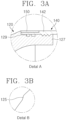
- FIG. 3A is an enlarged view illustrating the coupling mechanism of the end part of the metal boss 120.
- the outer circumferential surface of the end part 126 of the metal boss 120 is provided with a first screw part 127
- the inner circumferential surface of the liner is provided with a second screw part 142 at a position corresponding to the position at which the first screw part 127 is formed. Accordingly, the liner 140 screws with the metal boss while surrounding the end part 126 of the metal boss.
- a portion in which the metal boss 120 is coupled to the liner 140 may be additionally provided with a sealing means to prevent an internal fluid from leaking out between the metal boss and the liner.
- the inner side of the outer circumferential surface of the metal boss 120 may include an O-ring groove 129, and the space between the metal boss and the liner may be sealed by stably placing an 0-ring in the O-ring groove 129.
- a rigid ring 150 for pressing the plastic liner toward the metal boss may be provided at a position corresponding to the position in which the O-ring groove 129 is formed.
- the rigid ring may press the liner toward the metal boss along the outer circumference of the coupling part of the liner.
- the rigid ring may be made of a material identical to or different from that of the metal boss.
- the rigid ring may be made of a metal material such as steel, aluminum alloy, or stainless steel.
- FIG. 3A illustrates that on the outer circumferential surface of the end part 126 of the metal boss 120, the O-ring groove 129 is positioned on the inner side of the first screw part 127.
- the reverse is also possible in the present disclosure.
- FIG. 3B is an enlarged view of a portion of the dome part of the metal boss 120 in FIG. 2 .
- the outer surface of the dome part of the metal boss 120 is an overall smooth surface, but a predetermined region corresponding to the center portion of the dome part 124 may be provided with a catching ledge 125.
- the catching ledge 125 supports a reinforcing fiber that is wound on the curved surface of the dome part to reinforce the coupling strength between the metal boss and the liner in the pressure vessel.
- the catching ledge 125 is advantageous for supporting the reinforcing fiber forming a low-angle winding pattern.
- the reinforcing fiber for reinforcing the outer surface of the pressure vessel may be wound in a variety of ways.
- FIG. 4 exemplarily illustrates a winding pattern of a reinforcing fiber that reinforces the outer surface of pressure vessel 100.
- the winding pattern includes a hoop winding, which corresponds to the pressure in the X-axis direction and winds around the cylinder part of the pressure vessel, and a helical winding, which corresponds to the pressure in the Z-axis direction, which is the longitudinal direction of the pressure vessel.
- the helical winding includes a high-angle winding and a low-angle winding depending on the winding angle.
- the winding angle refers to an angle ⁇ that a winding pattern formed by a reinforcing fiber (w) and projected onto a two-dimensional plane including the Z axis of the pressure vessel (e.g., the XZ plane), makes with the Z axis.
- the low-angle winding refers to a winding having a winding angle of 55 degrees or less, or 50 degrees or less, and serves to suppress vessel expansion due to longitudinal pressure.
- the winding angle between the dome part and the helical pattern for longitudinal reinforcement is determined by the diameter of the neck part of the nozzle boss, the diameter of the vessel, and the aspect ratio of the vessel.
- the aspect ratio of the vessel is determined by the diameter of the neck part of the nozzle boss, the diameter of the vessel, and the aspect ratio of the vessel.
- the angle near 54 to 55 degrees, particularly near 54.75 degrees is a winding angle which enables reinforcement in both the longitudinal and diametrical directions, and whether the winding pattern of this angle may be formed is a very important factor.
- the catching ledge 125 of the metal boss 120 in the present disclosure supports the reinforcing fiber to enable low-angle winding.
- the catching ledge 125 may have various shapes to support low-angle winding.
- the catching ledge 125 may be embodied as a step structure, a groove structure, or a protrusion structure on the surface of the dome part. In FIG. 2 , the catching ledge 125 is based on a step structure.
- the catching ledge 125 may be a continuous structure along the circumference of the dome part.
- the step structure may have a ring shape.
- the catching ledge 125 may be implemented as a discontinuous structure, e.g., a discontinuous step along the circumference of the dome part.
- the catching ledge 125 should have a suitable size to support the reinforcing fiber.
- the height of the step should be preferably at least 2 mm.
- FIG. 5 schematically illustrates a cross-section of a pressure vessel according to another embodiment of the present disclosure.
- a coating layer 160 is formed on the metal boss 120 and the liner 140.
- the coating layer 160 includes a laminated structure by the winding pattern of the reinforcing fiber described above.
- the coating layer 160 may include a reinforcing fiber impregnated with a curable resin.
- the reinforcing fiber may be a carbon fiber, a glass fiber, or a synthetic polyamide fiber.
- the curable resin may be, but is not limited to, an epoxy resin or the like.
- the coating layer of the present disclosure covers the catching ledge at the center portion of the dome part, and the metal boss having a catching ledge structure enables winding of the catching ledge and a low-angle region inside the catching ledge.
- the present disclosure is applicable to gas storage vessels for storing various types of gases, such as hydrogen, nitrogen, natural gas, etc.
Landscapes
- Engineering & Computer Science (AREA)
- Mechanical Engineering (AREA)
- General Engineering & Computer Science (AREA)
- Filling Or Discharging Of Gas Storage Vessels (AREA)
Applications Claiming Priority (2)
| Application Number | Priority Date | Filing Date | Title |
|---|---|---|---|
| KR1020210185344A KR102719092B1 (ko) | 2021-12-22 | 2021-12-22 | 소직경 장축 압력용기 |
| PCT/KR2022/017623 WO2023120975A1 (ko) | 2021-12-22 | 2022-11-10 | 소직경 장축 압력용기 |
Publications (2)
| Publication Number | Publication Date |
|---|---|
| EP4455535A1 true EP4455535A1 (de) | 2024-10-30 |
| EP4455535A4 EP4455535A4 (de) | 2025-10-29 |
Family
ID=86902944
Family Applications (1)
| Application Number | Title | Priority Date | Filing Date |
|---|---|---|---|
| EP22911613.2A Pending EP4455535A4 (de) | 2021-12-22 | 2022-11-10 | Druckbehälter mit kleinem durchmesser und langer achse |
Country Status (4)
| Country | Link |
|---|---|
| US (1) | US20250067396A1 (de) |
| EP (1) | EP4455535A4 (de) |
| KR (1) | KR102719092B1 (de) |
| WO (1) | WO2023120975A1 (de) |
Family Cites Families (11)
| Publication number | Priority date | Publication date | Assignee | Title |
|---|---|---|---|---|
| JP5446033B2 (ja) * | 2009-03-19 | 2014-03-19 | トヨタ自動車株式会社 | Frpタンクの製造装置及び製造方法 |
| US8523002B2 (en) * | 2010-02-26 | 2013-09-03 | GM Global Technology Operations LLC | Embedded reinforcement sleeve for a pressure vessel |
| KR101437231B1 (ko) | 2012-11-23 | 2014-09-02 | 일진복합소재 주식회사 | 압력 용기 |
| JP2018066391A (ja) * | 2016-10-17 | 2018-04-26 | トヨタ自動車株式会社 | 圧力容器 |
| KR102463415B1 (ko) * | 2016-12-20 | 2022-11-03 | 현대자동차주식회사 | 보스부가 강화된 구조를 가지는 고압용기 |
| US10746354B2 (en) * | 2017-05-24 | 2020-08-18 | Hexagon Technology, As | Threaded boss for pressure vessel |
| JP6844465B2 (ja) * | 2017-08-08 | 2021-03-17 | トヨタ自動車株式会社 | 高圧容器 |
| WO2020002467A1 (en) * | 2018-06-26 | 2020-01-02 | Plastic Omnium Advanced Innovation And Research | Composite pressure vessel with boss connector |
| CN114391078B (zh) * | 2019-06-28 | 2023-04-11 | 莱纳玛公司 | 用于压缩气体储箱的安全快速填充的策略 |
| ES2944713T3 (es) * | 2019-08-30 | 2023-06-23 | Nproxx B V | Recipiente a presión |
| KR102789140B1 (ko) * | 2021-11-15 | 2025-03-31 | 코오롱스페이스웍스 주식회사 | 고압 저장 용기 |
-
2021
- 2021-12-22 KR KR1020210185344A patent/KR102719092B1/ko active Active
-
2022
- 2022-11-10 US US18/722,041 patent/US20250067396A1/en active Pending
- 2022-11-10 WO PCT/KR2022/017623 patent/WO2023120975A1/ko not_active Ceased
- 2022-11-10 EP EP22911613.2A patent/EP4455535A4/de active Pending
Also Published As
| Publication number | Publication date |
|---|---|
| US20250067396A1 (en) | 2025-02-27 |
| KR20230095660A (ko) | 2023-06-29 |
| KR102719092B1 (ko) | 2024-10-18 |
| EP4455535A4 (de) | 2025-10-29 |
| WO2023120975A1 (ko) | 2023-06-29 |
Similar Documents
| Publication | Publication Date | Title |
|---|---|---|
| CN102939496B (zh) | 高压罐及高压罐的制造方法 | |
| CA2212016C (en) | Composite conformable pressure vessel | |
| CN114719177B (zh) | 压力容器 | |
| US11472135B2 (en) | Method for manufacturing high-pressure tank | |
| US12247698B2 (en) | High-pressure tank and method for producing the same | |
| KR20180119956A (ko) | 압력 용기의 제조 방법 | |
| JP4393155B2 (ja) | 圧力容器 | |
| KR102322371B1 (ko) | 실린더부가 보강된 압력 용기 | |
| US11339923B1 (en) | Pressure vessel | |
| CN109140223B (zh) | 高压复合容器 | |
| CN114719175B (zh) | 压力容器 | |
| EP4455535A1 (de) | Druckbehälter mit kleinem durchmesser und langer achse | |
| JP2021076130A (ja) | タンク集合装置 | |
| US20240084967A1 (en) | Pressure vessel | |
| JP2005113971A (ja) | 耐圧容器用ライナ | |
| KR102598547B1 (ko) | 압력 용기 및 압력 용기의 제조 방법 | |
| RU2141073C1 (ru) | Сосуд высокого давления | |
| CN113414556A (zh) | 一种用于卫星压力容器的金属复合气口及其制造方法 | |
| KR20230040243A (ko) | 고압 저장 용기 및 그 제조 방법 | |
| US20070114234A1 (en) | Container and process for storing fuel | |
| CN117489970B (en) | Tank | |
| KR20230040241A (ko) | 고압 저장 용기 및 그 제조 방법 | |
| US20240044453A1 (en) | Tank | |
| US12404973B2 (en) | Tank | |
| KR102793829B1 (ko) | 고압 저장 용기 및 그 제조 방법 |
Legal Events
| Date | Code | Title | Description |
|---|---|---|---|
| STAA | Information on the status of an ep patent application or granted ep patent |
Free format text: STATUS: THE INTERNATIONAL PUBLICATION HAS BEEN MADE |
|
| PUAI | Public reference made under article 153(3) epc to a published international application that has entered the european phase |
Free format text: ORIGINAL CODE: 0009012 |
|
| STAA | Information on the status of an ep patent application or granted ep patent |
Free format text: STATUS: REQUEST FOR EXAMINATION WAS MADE |
|
| 17P | Request for examination filed |
Effective date: 20240722 |
|
| AK | Designated contracting states |
Kind code of ref document: A1 Designated state(s): AL AT BE BG CH CY CZ DE DK EE ES FI FR GB GR HR HU IE IS IT LI LT LU LV MC ME MK MT NL NO PL PT RO RS SE SI SK SM TR |
|
| DAV | Request for validation of the european patent (deleted) | ||
| DAX | Request for extension of the european patent (deleted) | ||
| A4 | Supplementary search report drawn up and despatched |
Effective date: 20250925 |
|
| RIC1 | Information provided on ipc code assigned before grant |
Ipc: F17C 1/06 20060101AFI20250919BHEP Ipc: F17C 13/00 20060101ALI20250919BHEP |