EP4455529A1 - Clamping device for connecting hose barbs - Google Patents
Clamping device for connecting hose barbs Download PDFInfo
- Publication number
- EP4455529A1 EP4455529A1 EP23170817.3A EP23170817A EP4455529A1 EP 4455529 A1 EP4455529 A1 EP 4455529A1 EP 23170817 A EP23170817 A EP 23170817A EP 4455529 A1 EP4455529 A1 EP 4455529A1
- Authority
- EP
- European Patent Office
- Prior art keywords
- locking mechanism
- hose barbs
- clamping device
- seal
- hose
- Prior art date
- Legal status (The legal status is an assumption and is not a legal conclusion. Google has not performed a legal analysis and makes no representation as to the accuracy of the status listed.)
- Pending
Links
Images




Classifications
-
- F—MECHANICAL ENGINEERING; LIGHTING; HEATING; WEAPONS; BLASTING
- F16—ENGINEERING ELEMENTS AND UNITS; GENERAL MEASURES FOR PRODUCING AND MAINTAINING EFFECTIVE FUNCTIONING OF MACHINES OR INSTALLATIONS; THERMAL INSULATION IN GENERAL
- F16L—PIPES; JOINTS OR FITTINGS FOR PIPES; SUPPORTS FOR PIPES, CABLES OR PROTECTIVE TUBING; MEANS FOR THERMAL INSULATION IN GENERAL
- F16L21/00—Joints with sleeve or socket
- F16L21/002—Sleeves or nipples for pipes of the same diameter; Reduction pieces
- F16L21/005—Sleeves or nipples for pipes of the same diameter; Reduction pieces made of elastic material, e.g. partly or completely surrounded by clamping devices
-
- F—MECHANICAL ENGINEERING; LIGHTING; HEATING; WEAPONS; BLASTING
- F16—ENGINEERING ELEMENTS AND UNITS; GENERAL MEASURES FOR PRODUCING AND MAINTAINING EFFECTIVE FUNCTIONING OF MACHINES OR INSTALLATIONS; THERMAL INSULATION IN GENERAL
- F16L—PIPES; JOINTS OR FITTINGS FOR PIPES; SUPPORTS FOR PIPES, CABLES OR PROTECTIVE TUBING; MEANS FOR THERMAL INSULATION IN GENERAL
- F16L25/00—Construction or details of pipe joints not provided for in, or of interest apart from, groups F16L13/00 - F16L23/00
- F16L25/12—Joints for pipes being spaced apart axially
Definitions
- the invention relates to a clamping device for fluidically and mechanically connecting two hose barbs.
- hoses which are often made of silicone.
- one end of the hose is pulled over the hose barb of the one component and the other end of the hose is pulled over the hose barb of the other component.
- the hose ends are fastened with cable ties or clamps, for example.
- the above problem is solved by a clamping device for fluidically and mechanically connecting two hose barbs.
- the clamping device comprises a seal and a locking mechanism, wherein the locking mechanism can be transferred from a mounting condition to an assembled condition.
- the hose barbs In the mounting condition, the hose barbs can be inserted into the clamping device, whereas in the assembled condition, these hose barbs are locked in place in a position in which free ends of the hose barbs face each other and the seal coaxially aligns and fluid-tightly connects the free ends.
- the invention is based on the finding that components usually comprise hose barbs for establishing fluid connections to other components.
- the clamping device according to the invention makes it possible to directly connect two hose barbs, so that no hose is required.
- the invention not only minimizes the process volume but also the overall volume of the system. This also means that tubing material is saved.
- the assembly is simplified and more secure, since the clamping mechanism aligns the hose barbs and no tube needs to be connected with cable ties or clamps anymore.
- the locking mechanism can comprise a fixture for attaching the locking mechanism to a retaining plate.
- the seal and the locking mechanism are a prefabricated unit.
- the seal is molded directly into the locking mechanisms. This means that the clamping device only comprises one part, which in turn further simplifies the assembly.
- the seal consists of a material resistant to irradiation and chemicals, like EPDM rubber, silicon, or a thermoplastic elastomer. These materials are suitable single-use materials which provide a sufficient chemical, temperature and irradiation stability when sterilized by heat, chemicals or radiation.
- the locking mechanism is preloaded into the assembled condition, such that a secure connection is ensured. Furthermore, having the locking mechanism preloaded into the assembled condition simplifies the assembly by automatically transferring the locking mechanism from the mounting condition into the assembled condition.
- the seal and the locking mechanism can form an adapter.
- the adapter is especially useful for connecting hose barbs having different inner diameters since it is provided to align the hose barbs coaxially.
- having the seal and the locking mechanism form an adapter reduces the amount of parts needed to form a fluidic and mechanical connection, which helps with reducing the volume and costs.
- the seal and the locking mechanism may comprise an intermediate section, which gradually adapts to the change in dimensions.
- the sealing function can be performed in two places, namely between the first hose barb and the intermediate area and between the second hose barb and the intermediate area. While this might slightly increase the system volume compared to a system, where two hose barbs with the same dimensions are connected, it ensures that the connection is possible at all and still compact and fluid-tight.
- the transfer of the locking mechanism from the mounting condition to the assembled condition is irreversible.
- the locking mechanism can be reversibly transferred between the mounting condition and the assembled condition.
- a reversible locking mechanism allows a better waste management and makes more recycling options available since the parts can be disassembled more easily.
- While the invention mainly relates to single-use systems, having a locking mechanism that can be reversibly transferred between the mounting and the assembled condition can still be an advantage, since that means that the locking mechanism can be used in multiple systems. In other words, once a process is finished, the locking mechanism can be transferred back into its mounting condition, allowing to disassemble the different components and then be used to assemble another set of components for a different process.
- the seal is a sleeve with an inner wall adapted to frusto-conical shapes of the free ends of the hose barbs facing each other.
- the seal comprises a primary sealing lip for engaging an outer surface of the free ends of the hose barbs and a secondary sealing lip for engaging an inner surface of the free ends of the hose barbs.
- the primary and secondary sealing lips are connected by a web and form a flexure bearing.
- the primary sealing lip is intended to fully seal the hose barbs
- the secondary sealing lip, together with the primary sealing lip is intended to align the hose barbs coaxially with one another.
- the seal comprises an axial sealing piece and two guide pieces for increasing the free end surfaces of the hose barbs.
- the axial sealing piece is placed centrally between the two guide pieces and is preferably an O-ring. While the guide pieces are made of hard plastic, the axial sealing piece can be compressed in the assembled condition by the hose barbs.
- One such locking mechanism comprises a ring element encompassing the seal. Further, the ring element has latching hooks on opposite sides and two external threads.
- the locking mechanism also comprises two nuts having inner wall sections adapted to frusto-conical shapes of the free ends of the hose barbs and internal threads, so that the nuts can be screwed onto the ring element. Thereby, the latching hooks are forced to engage behind the rear gripping edge surfaces of the hose barbs such that the free ends of the hose barbs are pressed against each other. By using threads, it is ensured that the clamping device can be disassembled as easily as it can be assembled.
- the locking mechanism comprises a first sleeve element and a second sleeve element inserted, preferably screwed, into the first sleeve element.
- Those sleeve elements surround the free ends of the hose barbs facing each other and are held in place in the assembled condition via a squeeze mechanism.
- the squeeze mechanism preferably includes radially movable slide elements, which engage behind rear gripping edge surfaces of the hose barbs in the assembled condition and have a keyhole contour adapted to the outer diameter of the hose barbs behind the gripping edges. This locking mechanism allows for an easy assembly since only the sliding elements need to be pushed into the correct position to fully secure the hose barb connection.
- the locking mechanism comprises two axially spring-loaded snap rings for engaging behind rear gripping edge surfaces of the hose barbs.
- the snap rings are held in place by a sleeve.
- This particular locking mechanism allows for a very simplified assembly, since the hose barbs only have to be inserted into the sleeve.
- the actual transition into the assembled state is provided by the spring-loaded snap rings, which are preloaded into the assembled condition.
- the axially preload force for the snap rings is given by elastomer springs or wave springs.
- the locking mechanism can also comprise a flexible O-ring between these spring-loaded snap rings and the sleeve.
- the locking mechanism comprises a double-sided flexure bearing forming a clamp, which automatically opens when the hose barbs are inserted and engages behind rear gripping edge surfaces of the hose barbs once the hose barbs are fully inserted.
- this locking mechanism consists of only one part, which simplifies the assembly.
- this locking mechanism is especially suitable to be part of a free pre-fabricated unit together with a seal.
- each seal can be used in combination with any one of the locking mechanisms. Further, any of the seals is only functional in combination with one of the locking mechanisms while any of the locking mechanisms requires a seal to be functional.
- Figure 1 shows a schematic drawing of a typical hose barb 10 comprising a mounting end 12 mounted to a component and an opposite free end 14.
- the free 14 end transitions into a frusto-conical shape 16, which forms a protruding gripping edge 18.
- the hose barb 10 is generally mounted to a component and generally used for fluid connection with another component. In particular, it will be described how two hose barbs 10 facing each other can be connected via a clamping device 8.
- Figure 2 shows an example of a seal 20, which can be used as part of the clamping device 8.
- the seal 20 is simply a sleeve 22 whose inner wall 24 is adapted to the frusto-conical shapes 16 of the opposing free ends 14 of the hose barbs 10 in order to align the free ends 14 of the hose barbs 10 coaxially with each other.
- a seal 20 comprising a primary sealing lip 26 and a secondary sealing lip 26, as shown in Figure 3 , can be used.
- the circumferential primary and secondary sealing lips 26, 28 are connected by a web 30.
- the web 30 and the sealing lips 26, 28 together form a flexure bearing.
- the primary sealing lip 26 fully seals the hose barbs 10 from the outside.
- the secondary sealing lip 28 on the other hand, is intended to align the hose barbs 10 coaxially with each other, together with the primary sealing lip 26.
- the seal 20 comprises an axial sealing piece in the form of an O-ring 34 and two guide pieces 36.
- the inside of the guide pieces 36 is adapted to the free ends 14 of the hose barbs 10, including the frusto-conical shape 16. Consequently, the guide pieces 36 increase the frontal area of the hose barbs 10.
- the ends of the guide pieces 36 facing away from the respective hose barbs 10 allow the O-ring to be centrally located in a groove 38 formed by the two guide pieces 36.
- the guide pieces 36 can be made of a hard plastic, while the O-ring 34 consists of a compressible material.
- a clamping device 8 comprising one of the seals 20 and one of the locking mechanisms 40 is used for fluidically and mechanically connecting the two opposing hose barbs 10.
- a first embodiment of the locking mechanism 40 shown in Figure 5 is used together with the seal 20 shown in Figure 2 .
- the locking mechanism 40 comprises a ring element 42, which encompasses the free ends 14 of the hose barbs 10.
- the ring element 42 has latching hooks 44 on each axial end of the ring element 42, which engage behind the gripping edge 18 of the hose barbs 10 in the assembled condition.
- the ring element 42 also has two external threads 46. These external threads 46 are used to screw two nuts 48 with internal threads 50 onto the ring element 42 in order to keep it in place.
- Figure 5A shows the mounting condition of the locking mechanism 40.
- the hose barbs 10 are inserted into the ring element 42.
- the frusto-conical shape 16 slightly pushes the latching hooks 44 apart while the free ends 14 of the hose barbs 10 are inserted before they snap back into place once they have passed the gripping edge 18.
- FIG. 6A and 6B An alternative locking mechanism 40 is shown in Figures 6A and 6B , using the seal 20 according to Figure 2 again.
- the locking mechanism 40 comprises a first sleeve element 52 and a second sleeve element 54 and two sliding elements 56 which can penetrate through the sleeve elements 52, 54, respectively.
- the first and second sleeve elements 52, 54 surround the free ends 14 of the hose barbs 10 as well as the seal 20.
- the sleeve elements 52, 54 can be screwed together via an internal thread of the first sleeve element 52 and an external thread of the second sleeve element 54.
- the threads are not shown in Figures 6A and 6B .
- the sliding elements 56 which have a keyhole contour, are inserted into openings of the first and second sleeve elements 52, 54, respectively.
- the free ends 14 of the hose barbs 10 are each inserted into one of the sleeve elements 52, 54 and through the larger part of the keyhole contour of the respective slide element 56, such that the sliding elements 56 are located behind the gripping edges 18.
- the sleeve elements 52, 54 are screwed together, pressing the free ends 14 of the hose barbs 10 against each other.
- the sliding elements 56 are radially moved such that the rims of the smaller parts of the keyhole contours forcibly engage behind the gripping edges 18 of the hose barbs 10.
- FIGS 7A and 7B Yet another embodiment of the clamping device 8 is shown in Figures 7A and 7B .
- the seal 20 comprising a primary sealing lip 26 and a secondary sealing lip 28, as shown in Figure 3 , is used.
- the locking mechanism 40 comprises a sleeve 58, two snap rings 60, and two springs 62 for axially spring-loading (biasing) the snap rings 60.
- the snap rings 60 engage with the gripping edges 18 of the hose barbs 10 and provide an increased surface for the sleeve 58 to hold the hose barbs 10 in place.
- the spring 62 in particular an elastomer spring or a wave spring, is located.
- one or two O-rings 66 can be used.
- an O-ring 66 is located in the left groove 64 and the spring 62 is located in the right groove 64 of the sleeve 58 in Figures 7A and 7B .
- each hose barb 10 is pushed into the sleeve 58 and, thus, into the spring 62 and the snap ring 60. While the free end 14 of the hose barb 10 is pushed through the spring 62 and the snap ring 60, the frusto-conical shape 16 pushes the spring 62 and the snap ring 60 apart.
- the snap ring 60 has a slit, allowing it to expand when the free end 14 of the hose barb 10 is inserted.
- the free ends 14 While pushing the free ends 14 into the sleeve 58, the free ends 14 are also pushed between the primary and secondary sealing lips 26, 28 of the seal 20.
- the sleeve 58 further pushes the free ends 14 of the hose barbs 10 together and also ensures that the snap ring 60 and spring 62 engage with the gripping edges 18 of the hose barbs 10.
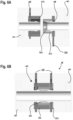
- Figures 8A and 8B show yet another embodiment of the clamping device 8, using the seal shown in Figure 4 .
- the locking mechanism 40 comprises a double-sided flexure bearing 68, which forms a clamp.
- the flexure bearing 68 comprises multiple cut-outs 70.
- This clamping device 8 is especially suitable for the seal 20, or at least parts of the seal 20, and the locking mechanism 40 to be formed as one piece.
- each of the different locking mechanisms 40 is shown with a particular seal 20, other combinations of locking mechanisms 40 and seals 20 are possible. In general, each locking mechanism 40 is only functional in combination with one of the seals 20, while each seal 20 is only functional in combination with one of the locking mechanisms 40 for the purpose of the present invention.
Landscapes
- Engineering & Computer Science (AREA)
- General Engineering & Computer Science (AREA)
- Mechanical Engineering (AREA)
- Quick-Acting Or Multi-Walled Pipe Joints (AREA)
- Clamps And Clips (AREA)
Abstract
Description
- The invention relates to a clamping device for fluidically and mechanically connecting two hose barbs.
- Single-use systems in the field of "separations" and "fluid management" are mostly used to transport liquids and gases. Components such as filters, sensors, and actuators are connected to each other via hoses, which are often made of silicone. In order to create a tight connection, one end of the hose is pulled over the hose barb of the one component and the other end of the hose is pulled over the hose barb of the other component. The hose ends are fastened with cable ties or clamps, for example.
- In particular for systems used in chromatography, filtration, and virus inactivation, it is desired to keep the volume of the hoses and components as small as possible in order to avoid a large amount of valuable medium remaining in the system at the end of the process. This is especially important when only a limited amount of medium is available and/or when the medium is of high monetary value.
- One option is to rinse the system after the end of a process. However, this leads to a dilution of the processed medium such that it cannot be used for further processes.
- In order to design components with the smallest possible volume, it is advantageous to bundle components in individual assemblies. This also minimizes the tube length between the components. However, a minimum tube length is usually required in order to assemble the components properly.
- It is an object of the invention to simplify the assembly and to minimize the volume of systems where fluid is transported from one component to another.
- The above problem is solved by a clamping device for fluidically and mechanically connecting two hose barbs. The clamping device comprises a seal and a locking mechanism, wherein the locking mechanism can be transferred from a mounting condition to an assembled condition. In the mounting condition, the hose barbs can be inserted into the clamping device, whereas in the assembled condition, these hose barbs are locked in place in a position in which free ends of the hose barbs face each other and the seal coaxially aligns and fluid-tightly connects the free ends.
- The invention is based on the finding that components usually comprise hose barbs for establishing fluid connections to other components. The clamping device according to the invention makes it possible to directly connect two hose barbs, so that no hose is required. Thus, the invention not only minimizes the process volume but also the overall volume of the system. This also means that tubing material is saved. Furthermore, the assembly is simplified and more secure, since the clamping mechanism aligns the hose barbs and no tube needs to be connected with cable ties or clamps anymore.
- To further increase the stability of the overall system, the locking mechanism can comprise a fixture for attaching the locking mechanism to a retaining plate.
- According to a preferred embodiment of the invention, the seal and the locking mechanism are a prefabricated unit. Preferably, the seal is molded directly into the locking mechanisms. This means that the clamping device only comprises one part, which in turn further simplifies the assembly.
- Preferably, the seal consists of a material resistant to irradiation and chemicals, like EPDM rubber, silicon, or a thermoplastic elastomer. These materials are suitable single-use materials which provide a sufficient chemical, temperature and irradiation stability when sterilized by heat, chemicals or radiation.
- According to a preferred embodiment of the invention, the locking mechanism is preloaded into the assembled condition, such that a secure connection is ensured. Furthermore, having the locking mechanism preloaded into the assembled condition simplifies the assembly by automatically transferring the locking mechanism from the mounting condition into the assembled condition.
- In order to connect two hose barbs having different dimensions, the seal and the locking mechanism can form an adapter. The adapter is especially useful for connecting hose barbs having different inner diameters since it is provided to align the hose barbs coaxially. Furthermore, having the seal and the locking mechanism form an adapter reduces the amount of parts needed to form a fluidic and mechanical connection, which helps with reducing the volume and costs.
- For hose barbs having strongly differing inner diameters, the seal and the locking mechanism may comprise an intermediate section, which gradually adapts to the change in dimensions. In that case, the sealing function can be performed in two places, namely between the first hose barb and the intermediate area and between the second hose barb and the intermediate area. While this might slightly increase the system volume compared to a system, where two hose barbs with the same dimensions are connected, it ensures that the connection is possible at all and still compact and fluid-tight.
- According to a first concept of the invention, the transfer of the locking mechanism from the mounting condition to the assembled condition is irreversible.
- According to an alternative second concept of the invention, the locking mechanism can be reversibly transferred between the mounting condition and the assembled condition. A reversible locking mechanism allows a better waste management and makes more recycling options available since the parts can be disassembled more easily.
- While the invention mainly relates to single-use systems, having a locking mechanism that can be reversibly transferred between the mounting and the assembled condition can still be an advantage, since that means that the locking mechanism can be used in multiple systems. In other words, once a process is finished, the locking mechanism can be transferred back into its mounting condition, allowing to disassemble the different components and then be used to assemble another set of components for a different process.
- According to an embodiment of the invention, the seal is a sleeve with an inner wall adapted to frusto-conical shapes of the free ends of the hose barbs facing each other. This is a rather simple design, which leads to low production costs and, hence, reduces the overall costs involved.
- According to another embodiment of the invention, the seal comprises a primary sealing lip for engaging an outer surface of the free ends of the hose barbs and a secondary sealing lip for engaging an inner surface of the free ends of the hose barbs. The primary and secondary sealing lips are connected by a web and form a flexure bearing. In other words, the primary sealing lip is intended to fully seal the hose barbs, while the secondary sealing lip, together with the primary sealing lip, is intended to align the hose barbs coaxially with one another. In order to protect the flexure bearing, it is possible to place rings between the frontal surface of the hose barbs and the flexure bearing.
- According to yet another embodiment of the invention, the seal comprises an axial sealing piece and two guide pieces for increasing the free end surfaces of the hose barbs. The axial sealing piece is placed centrally between the two guide pieces and is preferably an O-ring. While the guide pieces are made of hard plastic, the axial sealing piece can be compressed in the assembled condition by the hose barbs.
- In order for any of the seals to be functional, they need to be used in combination with a locking mechanism. One such locking mechanism according to the invention comprises a ring element encompassing the seal. Further, the ring element has latching hooks on opposite sides and two external threads. The locking mechanism also comprises two nuts having inner wall sections adapted to frusto-conical shapes of the free ends of the hose barbs and internal threads, so that the nuts can be screwed onto the ring element. Thereby, the latching hooks are forced to engage behind the rear gripping edge surfaces of the hose barbs such that the free ends of the hose barbs are pressed against each other. By using threads, it is ensured that the clamping device can be disassembled as easily as it can be assembled.
- According to another embodiment of the invention, the locking mechanism comprises a first sleeve element and a second sleeve element inserted, preferably screwed, into the first sleeve element. Those sleeve elements surround the free ends of the hose barbs facing each other and are held in place in the assembled condition via a squeeze mechanism. The squeeze mechanism preferably includes radially movable slide elements, which engage behind rear gripping edge surfaces of the hose barbs in the assembled condition and have a keyhole contour adapted to the outer diameter of the hose barbs behind the gripping edges. This locking mechanism allows for an easy assembly since only the sliding elements need to be pushed into the correct position to fully secure the hose barb connection.
- According to another embodiment of the invention, the locking mechanism comprises two axially spring-loaded snap rings for engaging behind rear gripping edge surfaces of the hose barbs. The snap rings are held in place by a sleeve. This particular locking mechanism allows for a very simplified assembly, since the hose barbs only have to be inserted into the sleeve. The actual transition into the assembled state is provided by the spring-loaded snap rings, which are preloaded into the assembled condition. Preferably, the axially preload force for the snap rings is given by elastomer springs or wave springs. Alternatively, the locking mechanism can also comprise a flexible O-ring between these spring-loaded snap rings and the sleeve.
- According to an embodiment of the invention, the locking mechanism comprises a double-sided flexure bearing forming a clamp, which automatically opens when the hose barbs are inserted and engages behind rear gripping edge surfaces of the hose barbs once the hose barbs are fully inserted. Again, this locking mechanism consists of only one part, which simplifies the assembly. Furthermore, this locking mechanism is especially suitable to be part of a free pre-fabricated unit together with a seal.
- It is to be noted that each seal can be used in combination with any one of the locking mechanisms. Further, any of the seals is only functional in combination with one of the locking mechanisms while any of the locking mechanisms requires a seal to be functional.
- Further features and advantages of the invention will become apparent from the following description and from the accompanying drawings to which reference is made. In the schematic drawings:
-
Figure 1 shows a schematic illustration of a hose barb; -
Figure 2 shows a schematic cross-section of two opposing hose barbs with an embodiment of a seal; -
Figure 3 shows a schematic cross-section of two opposing hose barbs with an alternative embodiment of a seal; -
Figure 4 shows another schematic cross-section of two opposing hose barbs with yet another alternative embodiment of a seal; -
Figure 5 shows a schematic cross-section of a clamping device having a locking mechanism according to a first embodiment, whereinFigure 5A shows the mounting condition of the locking mechanism whileFigure 5B shows the assembled condition of the locking mechanism; -
Figure 6 shows a schematic cross-section of a clamping device having an alternative locking mechanism according to a second embodiment, whereinFigure 6A shows the mounting condition of the locking mechanism andFigure 6B shows the assembled condition of the locking mechanism; -
Figure 7 shows a schematic cross-section of a clamping device having another locking mechanism according to a third embodiment, whereinFigure 7A shows the mounting condition of the locking mechanism andFigure 7B shows the assembled condition of the locking mechanism; and -
Figure 8 shows a schematic cross-section of a clamping device with yet another locking mechanism according to a fourth embodiment, whereinFigure 8A shows the mounting condition of the locking mechanism andFigure 8B shows the assembled condition of the locking mechanism. -
Figure 1 shows a schematic drawing of atypical hose barb 10 comprising a mountingend 12 mounted to a component and an oppositefree end 14. The free 14 end transitions into a frusto-conical shape 16, which forms a protruding grippingedge 18. - The
hose barb 10 is generally mounted to a component and generally used for fluid connection with another component. In particular, it will be described how twohose barbs 10 facing each other can be connected via aclamping device 8. -
Figure 2 shows an example of aseal 20, which can be used as part of theclamping device 8. In this case, theseal 20 is simply a sleeve 22 whose inner wall 24 is adapted to the frusto-conical shapes 16 of the opposing free ends 14 of thehose barbs 10 in order to align the free ends 14 of thehose barbs 10 coaxially with each other. - Alternatively, a
seal 20 comprising aprimary sealing lip 26 and asecondary sealing lip 26, as shown inFigure 3 , can be used. The circumferential primary andsecondary sealing lips lips - The
primary sealing lip 26 fully seals thehose barbs 10 from the outside. Thesecondary sealing lip 28 on the other hand, is intended to align thehose barbs 10 coaxially with each other, together with theprimary sealing lip 26. - Since the free ends 14 of the
hose barbs 10 are pressing against the web 30 in an assembled condition, it is possible to place rings 32 between the free ends 14 and the web 30. That way the risk of damage caused by thehose barbs 10 pressing against the web 30 is reduced. - A further embodiment of the
seal 20 is shown inFigure 4 . Here, theseal 20 comprises an axial sealing piece in the form of an O-ring 34 and twoguide pieces 36. The inside of theguide pieces 36 is adapted to the free ends 14 of thehose barbs 10, including the frusto-conical shape 16. Consequently, theguide pieces 36 increase the frontal area of thehose barbs 10. - The ends of the
guide pieces 36 facing away from therespective hose barbs 10 allow the O-ring to be centrally located in agroove 38 formed by the twoguide pieces 36. Theguide pieces 36 can be made of a hard plastic, while the O-ring 34 consists of a compressible material. - All of the three
seals 20 described above are only functional in combination with one of the lockingmechanisms 40 depicted inFigures 5 to 8 . Aclamping device 8 comprising one of theseals 20 and one of the lockingmechanisms 40 is used for fluidically and mechanically connecting the two opposinghose barbs 10. - A first embodiment of the
locking mechanism 40 shown inFigure 5 is used together with theseal 20 shown inFigure 2 . Thelocking mechanism 40 comprises aring element 42, which encompasses the free ends 14 of thehose barbs 10. In particular, thering element 42 has latching hooks 44 on each axial end of thering element 42, which engage behind the grippingedge 18 of thehose barbs 10 in the assembled condition. Thering element 42 also has twoexternal threads 46. Theseexternal threads 46 are used to screw twonuts 48 withinternal threads 50 onto thering element 42 in order to keep it in place. -
Figure 5A shows the mounting condition of thelocking mechanism 40. In a first step, thehose barbs 10 are inserted into thering element 42. The frusto-conical shape 16 slightly pushes the latching hooks 44 apart while the free ends 14 of thehose barbs 10 are inserted before they snap back into place once they have passed thegripping edge 18. - In a second step, the nuts 48 are screwed onto the
ring element 42, which forces the latching hooks 44 to engage with thegripping edges 18 of thehose barbs 10. Consequently, the free ends 14 of thehose barbs 10 are pressed against each other. Furthermore, the sleeve 22 is pressed against the free ends 14 of thehose barbs 10 from three directions ensuring a fluid-tight seal. This assembled condition is shown inFigure 5B . - An
alternative locking mechanism 40 is shown inFigures 6A and 6B , using theseal 20 according toFigure 2 again. Thelocking mechanism 40 comprises afirst sleeve element 52 and asecond sleeve element 54 and two slidingelements 56 which can penetrate through thesleeve elements - The first and
second sleeve elements hose barbs 10 as well as theseal 20. - In order to ensure that the
sleeve elements first sleeve element 52 and an external thread of thesecond sleeve element 54. For the sake of simplicity, the threads are not shown inFigures 6A and 6B . - The sliding
elements 56, which have a keyhole contour, are inserted into openings of the first andsecond sleeve elements hose barbs 10 are each inserted into one of thesleeve elements respective slide element 56, such that the slidingelements 56 are located behind the gripping edges 18. Thesleeve elements hose barbs 10 against each other. In order to fully lock thehose barbs 10 into place, the slidingelements 56 are radially moved such that the rims of the smaller parts of the keyhole contours forcibly engage behind thegripping edges 18 of thehose barbs 10. - In the assembled condition shown in
Figure 6B , thehose barbs 10 cannot be removed from theclamping device 8 since the smaller parts of the keyhole contours of the slidingelements 56 have a smaller diameter than the gripping edges 18. - Yet another embodiment of the
clamping device 8 is shown inFigures 7A and 7B . Here, theseal 20 comprising aprimary sealing lip 26 and asecondary sealing lip 28, as shown inFigure 3 , is used. - The
locking mechanism 40 comprises asleeve 58, two snap rings 60, and twosprings 62 for axially spring-loading (biasing) the snap rings 60. The snap rings 60 engage with thegripping edges 18 of thehose barbs 10 and provide an increased surface for thesleeve 58 to hold thehose barbs 10 in place. Between eachsnap ring 60 and a sidewall of thegroove 64, thespring 62, in particular an elastomer spring or a wave spring, is located. - As an alternative to one or both
springs 62, one or two O-rings 66 can be used. For illustrative purposes, an O-ring 66 is located in theleft groove 64 and thespring 62 is located in theright groove 64 of thesleeve 58 inFigures 7A and 7B . - In
Figure 7A , the mounting condition is shown. Thefree end 14 of eachhose barb 10 is pushed into thesleeve 58 and, thus, into thespring 62 and thesnap ring 60. While thefree end 14 of thehose barb 10 is pushed through thespring 62 and thesnap ring 60, the frusto-conical shape 16 pushes thespring 62 and thesnap ring 60 apart. For this purpose, thesnap ring 60 has a slit, allowing it to expand when thefree end 14 of thehose barb 10 is inserted. - Once the gripping
edge 18 has been pushed through thesnap ring 60 and thespring 62, they spring back into their original position and prevent thehose barb 10 from being pulled back. - While pushing the free ends 14 into the
sleeve 58, the free ends 14 are also pushed between the primary andsecondary sealing lips seal 20. Thesleeve 58 further pushes the free ends 14 of thehose barbs 10 together and also ensures that thesnap ring 60 andspring 62 engage with thegripping edges 18 of thehose barbs 10. -
Figures 8A and 8B show yet another embodiment of theclamping device 8, using the seal shown inFigure 4 . - The
locking mechanism 40 comprises a double-sided flexure bearing 68, which forms a clamp. In order to be flexible enough to widen in the mounting condition such that the free ends 14 of thehose barbs 10 can be inserted, the flexure bearing 68 comprises multiple cut-outs 70. - In
Figure 8A , one of thehose barbs 10 has already been inserted into the flexure bearing 68 as well as into one of theguide pieces 36 of theseal 20, which is attached to the O-ring 34. In a next step, thesecond hose barb 10 is pushed into the flexure bearing 68 together with theother guide piece 36. Thanks to the cut-outs 70 of the flexure bearing 68, the flexure bearing 68 can slightly expand in order to let theguide piece 36 and thefree end 14 of thehose barb 10 pass. Once the grippingedge 18 has been inserted into the flexure bearing 68, the flexure bearing 68 retreats back into its original form, which is shown inFigure 8B . - This
clamping device 8 is especially suitable for theseal 20, or at least parts of theseal 20, and thelocking mechanism 40 to be formed as one piece. - It is to be noted that while each of the
different locking mechanisms 40 is shown with aparticular seal 20, other combinations of lockingmechanisms 40 and seals 20 are possible. In general, each lockingmechanism 40 is only functional in combination with one of theseals 20, while eachseal 20 is only functional in combination with one of the lockingmechanisms 40 for the purpose of the present invention. -
- 8
- clamping device
- 10
- hose barb
- 12
- mounting end
- 14
- free end
- 16
- frusto-conical shape
- 18
- gripping edge
- 20
- seal
- 22
- sleeve (seal)
- 24
- inner wall
- 26
- primary sealing lip
- 28
- secondary sealing lip
- 30
- web
- 32
- rings
- 34
- O-ring
- 36
- guide pieces
- 38
- groove
- 40
- locking mechanism
- 42
- ring element
- 44
- latching hooks
- 46
- external threads
- 48
- nuts
- 50
- internal threads
- 52
- first sleeve element
- 54
- second sleeve element
- 56
- slide elements
- 58
- sleeve (locking mechanism)
- 60
- snap ring
- 62
- spring
- 64
- groove
- 66
- O-ring
- 68
- flexure bearing
- 70
- cut-outs
Claims (16)
- A clamping device (8) for fluidically and mechanically connecting two hose barbs (10), the clamping device comprising a seal (20) and a locking mechanism (40), wherein the locking mechanism (40) can be transferred from a mounting condition, in which the hose barbs (10) can be inserted into the clamping device (8), to an assembled condition, in which the hose barbs are locked in place in a position in which free ends (14) of the hose barbs (10) face each other and the seal (20) coaxially aligns and fluid-tightly connects the free ends (14).
- The clamping device (8) according to claim 1, wherein the locking mechanism (40) comprises a fixture for attaching the locking mechanism (40) to a retaining plate.
- The clamping device (8) according to any of the preceding claims, wherein the seal (20) and the locking mechanism (40) are a prefabricated unit, wherein the seal (20) is preferably moulded directly into the locking mechanism (40).
- The clamping device (8) according to any of the preceding claims, wherein the seal (20) consists of a material resistant to irradiation and chemicals, preferably EPDM rubber or silicone or a thermoplastic elastomer or a fluoroelastomer polymer (FPM).
- The clamping device (8) according to any of the preceding claims, wherein the locking mechanism (40) is pre-loaded into the assembled condition.
- The clamping device (8) according to any of the preceding claims, wherein the seal (20) and the locking mechanism (40) form an adapter so as to connect two hose barbs (10) having different dimensions.
- The clamping device (8) according to claim 6, wherein the seal (20) and the locking mechanism (40) comprise an intermediate section which gradually adapts to the change in dimensions.
- The clamping device (8) according to any of the preceding claims, wherein transfer of the locking mechanism (40) from the mounting condition to the assembled condition is irreversible.
- The clamping device (8) according to any of claims 1 to 7, wherein the locking mechanism (40) can be reversibly transferred between the mounting condition and the assembled condition.
- The clamping device (8) according to any of the preliminary claims, wherein the seal (20) is a sleeve (22) with an inner wall (24) adapted to frusto-conical shapes (16) of the free ends (14) of the hose barbs (10) facing each other.
- The clamping device (8) according to any of claims 1 to 9, wherein the seal (20) comprises a primary sealing lip (26) for engaging an outer surface of the free ends (14) of the hose barbs (10) and a secondary sealing lip (28) for engaging an inner surface of the free ends (14) of the hose barbs (10), the primary and secondary sealing lips (26, 28) being connected by a web (30) so as to form a flexure bearing.
- The clamping device (8) according to any of claims 1 to 9, wherein the seal (20) comprises an axial sealing piece, preferably an O-ring (34), and two guide pieces (36) for increasing the free end surfaces of the hose barbs (10), wherein the axial sealing piece is placed centrally between the two guide pieces (36).
- The clamping device (8) according to any of the preceding claims, wherein the locking mechanism (40) comprises a ring element (42) encompassing the seal (20), the ring element (42) having latching hooks (44) on opposite sides and two external threads (46), the locking mechanism (40) further comprising two nuts (48) having inner wall sections adapted to frusto-conical shapes (16) of the free ends (14) of the hose barbs (10) and internal threads (50), so that the nuts (48) can be screwed onto the ring element (42), thereby forcing the latching hooks (44) to engage behind rear gripping edge (18) surfaces of the hose barbs (10) and pressing the free ends (14) of the hose barbs (10) against each other.
- The clamping device (8) according to any of claims 1 to 12, wherein the locking mechanism (40) comprises a first sleeve element (52) and a second sleeve element (54) inserted, preferably screwed, into the first sleeve element (52), both sleeve elements (52, 54) surrounding the free ends (14) of the hose barbs (10) facing each other and being held in place in the assembled condition via a squeeze mechanism, the squeeze mechanism preferably including radially movable slide elements (56) engaging behind rear gripping edge (18) surfaces of the hose barbs (10) in the assembled condition and having a keyhole contour adapted to the outer diameter of the hose barbs (10) behind the gripping edges (18).
- The clamping device (8) according to any of claims 1 to 12, wherein the locking mechanism (40) comprises two axially spring-loaded snap rings (60) for engaging behind rear gripping edge (18) surfaces of the hose barbs (10), the snap rings (60) being held in a sleeve (58).
- The clamping mechanism (8) according to any of claims 1 to 12, wherein the locking mechanism (40) comprises a double-sided flexure bearing (68) forming a clamp which automatically opens when the hose barbs (10) are inserted and engages behind rear gripping edge (18) surfaces of the hose barbs (10) when the hose barbs (10) are fully inserted.
Priority Applications (2)
| Application Number | Priority Date | Filing Date | Title |
|---|---|---|---|
| EP23170817.3A EP4455529A1 (en) | 2023-04-28 | 2023-04-28 | Clamping device for connecting hose barbs |
| US18/647,006 US20240360932A1 (en) | 2023-04-28 | 2024-04-26 | Clamping device for connecting hose barbs |
Applications Claiming Priority (1)
| Application Number | Priority Date | Filing Date | Title |
|---|---|---|---|
| EP23170817.3A EP4455529A1 (en) | 2023-04-28 | 2023-04-28 | Clamping device for connecting hose barbs |
Publications (2)
| Publication Number | Publication Date |
|---|---|
| EP4455529A1 true EP4455529A1 (en) | 2024-10-30 |
| EP4455529A9 EP4455529A9 (en) | 2025-11-05 |
Family
ID=86282334
Family Applications (1)
| Application Number | Title | Priority Date | Filing Date |
|---|---|---|---|
| EP23170817.3A Pending EP4455529A1 (en) | 2023-04-28 | 2023-04-28 | Clamping device for connecting hose barbs |
Country Status (2)
| Country | Link |
|---|---|
| US (1) | US20240360932A1 (en) |
| EP (1) | EP4455529A1 (en) |
Citations (3)
| Publication number | Priority date | Publication date | Assignee | Title |
|---|---|---|---|---|
| DE689184C (en) * | 1936-01-31 | 1940-03-13 | Continental Gummi Werke Akt Ge | Noise-dampening pipe adapter |
| US2726682A (en) * | 1952-11-07 | 1955-12-13 | Aeroduct Inc | Flexible duct |
| GB1295176A (en) * | 1969-08-27 | 1972-11-01 |
-
2023
- 2023-04-28 EP EP23170817.3A patent/EP4455529A1/en active Pending
-
2024
- 2024-04-26 US US18/647,006 patent/US20240360932A1/en active Pending
Patent Citations (3)
| Publication number | Priority date | Publication date | Assignee | Title |
|---|---|---|---|---|
| DE689184C (en) * | 1936-01-31 | 1940-03-13 | Continental Gummi Werke Akt Ge | Noise-dampening pipe adapter |
| US2726682A (en) * | 1952-11-07 | 1955-12-13 | Aeroduct Inc | Flexible duct |
| GB1295176A (en) * | 1969-08-27 | 1972-11-01 |
Also Published As
| Publication number | Publication date |
|---|---|
| US20240360932A1 (en) | 2024-10-31 |
| EP4455529A9 (en) | 2025-11-05 |
Similar Documents
| Publication | Publication Date | Title |
|---|---|---|
| RU2698381C1 (en) | Coupling with retainer with tabs | |
| CN100547279C (en) | Barb clamp | |
| US8662541B2 (en) | Fittings for sealed retention to end portions of pipes and related methods | |
| US4070046A (en) | Pipe and tubing connecting sleeve | |
| US6123363A (en) | Self-centering low profile connection with trapped gasket | |
| EP0753696B1 (en) | Gasket assembly for a fluid coupling | |
| CN105917154A (en) | Pipe connection fitting | |
| US20080203723A1 (en) | Detachable pipe joint and joining method | |
| CN112543849B (en) | End fitting for pipe construction | |
| AU2018202811A1 (en) | Coupling and seal | |
| EP4455529A9 (en) | Clamping device for connecting hose barbs | |
| EP3001085B1 (en) | Fitting for multilayer pipes and assembly method thereof | |
| US11603950B2 (en) | Development of fuseal mechanical joint | |
| CN111684163A (en) | Apparatus for establishing piping system connections and method of use | |
| US12222057B2 (en) | Fluid connection assembly | |
| KR20220146518A (en) | Non-Metallic Fluid Couplings | |
| CA3118512C (en) | Multi-part connector assembly | |
| RU2782523C1 (en) | Multicomponent connecting node | |
| HK40029399A (en) | Coupling having tabbed retainer | |
| CN120769962A (en) | Fluid connection assembly with removable retainer | |
| JP6913541B2 (en) | Connection structure of fluid equipment | |
| HK40029399B (en) | Coupling having tabbed retainer | |
| WO2003025451A1 (en) | Pipe connectors | |
| HK1258389B (en) | Coupling having tabbed retainer | |
| CA2232856A1 (en) | Quick connector with confirmation feature |
Legal Events
| Date | Code | Title | Description |
|---|---|---|---|
| PUAI | Public reference made under article 153(3) epc to a published international application that has entered the european phase |
Free format text: ORIGINAL CODE: 0009012 |
|
| STAA | Information on the status of an ep patent application or granted ep patent |
Free format text: STATUS: THE APPLICATION HAS BEEN PUBLISHED |
|
| AK | Designated contracting states |
Kind code of ref document: A1 Designated state(s): AL AT BE BG CH CY CZ DE DK EE ES FI FR GB GR HR HU IE IS IT LI LT LU LV MC ME MK MT NL NO PL PT RO RS SE SI SK SM TR |
|
| STAA | Information on the status of an ep patent application or granted ep patent |
Free format text: STATUS: REQUEST FOR EXAMINATION WAS MADE |
|
| 17P | Request for examination filed |
Effective date: 20250404 |
|
| STAA | Information on the status of an ep patent application or granted ep patent |
Free format text: STATUS: EXAMINATION IS IN PROGRESS |
|
| 17Q | First examination report despatched |
Effective date: 20250716 |
|
| GRAP | Despatch of communication of intention to grant a patent |
Free format text: ORIGINAL CODE: EPIDOSNIGR1 |
|
| STAA | Information on the status of an ep patent application or granted ep patent |
Free format text: STATUS: GRANT OF PATENT IS INTENDED |
|
| INTG | Intention to grant announced |
Effective date: 20260127 |