EP4455518A1 - Betätigungsvorrichtung für ein getriebesystem - Google Patents
Betätigungsvorrichtung für ein getriebesystem Download PDFInfo
- Publication number
- EP4455518A1 EP4455518A1 EP24170352.9A EP24170352A EP4455518A1 EP 4455518 A1 EP4455518 A1 EP 4455518A1 EP 24170352 A EP24170352 A EP 24170352A EP 4455518 A1 EP4455518 A1 EP 4455518A1
- Authority
- EP
- European Patent Office
- Prior art keywords
- actuating
- receiving part
- rotation
- shaft
- axis
- Prior art date
- Legal status (The legal status is an assumption and is not a legal conclusion. Google has not performed a legal analysis and makes no representation as to the accuracy of the status listed.)
- Granted
Links
Images


Classifications
-
- F—MECHANICAL ENGINEERING; LIGHTING; HEATING; WEAPONS; BLASTING
- F16—ENGINEERING ELEMENTS AND UNITS; GENERAL MEASURES FOR PRODUCING AND MAINTAINING EFFECTIVE FUNCTIONING OF MACHINES OR INSTALLATIONS; THERMAL INSULATION IN GENERAL
- F16H—GEARING
- F16H63/00—Control outputs from the control unit to change-speed- or reversing-gearings for conveying rotary motion or to other devices than the final output mechanism
- F16H63/02—Final output mechanisms therefor; Actuating means for the final output mechanisms
- F16H63/30—Constructional features of the final output mechanisms
- F16H63/304—Constructional features of the final output mechanisms the final output mechanisms comprising elements moved by electrical or magnetic force
-
- F—MECHANICAL ENGINEERING; LIGHTING; HEATING; WEAPONS; BLASTING
- F16—ENGINEERING ELEMENTS AND UNITS; GENERAL MEASURES FOR PRODUCING AND MAINTAINING EFFECTIVE FUNCTIONING OF MACHINES OR INSTALLATIONS; THERMAL INSULATION IN GENERAL
- F16H—GEARING
- F16H61/00—Control functions within control units of change-speed- or reversing-gearings for conveying rotary motion ; Control of exclusively fluid gearing, friction gearing, gearings with endless flexible members or other particular types of gearing
- F16H61/26—Generation or transmission of movements for final actuating mechanisms
-
- F—MECHANICAL ENGINEERING; LIGHTING; HEATING; WEAPONS; BLASTING
- F16—ENGINEERING ELEMENTS AND UNITS; GENERAL MEASURES FOR PRODUCING AND MAINTAINING EFFECTIVE FUNCTIONING OF MACHINES OR INSTALLATIONS; THERMAL INSULATION IN GENERAL
- F16H—GEARING
- F16H63/00—Control outputs from the control unit to change-speed- or reversing-gearings for conveying rotary motion or to other devices than the final output mechanism
- F16H63/02—Final output mechanisms therefor; Actuating means for the final output mechanisms
- F16H63/30—Constructional features of the final output mechanisms
-
- F—MECHANICAL ENGINEERING; LIGHTING; HEATING; WEAPONS; BLASTING
- F16—ENGINEERING ELEMENTS AND UNITS; GENERAL MEASURES FOR PRODUCING AND MAINTAINING EFFECTIVE FUNCTIONING OF MACHINES OR INSTALLATIONS; THERMAL INSULATION IN GENERAL
- F16H—GEARING
- F16H61/00—Control functions within control units of change-speed- or reversing-gearings for conveying rotary motion ; Control of exclusively fluid gearing, friction gearing, gearings with endless flexible members or other particular types of gearing
- F16H61/26—Generation or transmission of movements for final actuating mechanisms
- F16H61/28—Generation or transmission of movements for final actuating mechanisms with at least one movement of the final actuating mechanism being caused by a non-mechanical force, e.g. power-assisted
- F16H2061/2869—Cam or crank gearing
-
- F—MECHANICAL ENGINEERING; LIGHTING; HEATING; WEAPONS; BLASTING
- F16—ENGINEERING ELEMENTS AND UNITS; GENERAL MEASURES FOR PRODUCING AND MAINTAINING EFFECTIVE FUNCTIONING OF MACHINES OR INSTALLATIONS; THERMAL INSULATION IN GENERAL
- F16H—GEARING
- F16H63/00—Control outputs from the control unit to change-speed- or reversing-gearings for conveying rotary motion or to other devices than the final output mechanism
- F16H63/02—Final output mechanisms therefor; Actuating means for the final output mechanisms
- F16H63/30—Constructional features of the final output mechanisms
- F16H63/304—Constructional features of the final output mechanisms the final output mechanisms comprising elements moved by electrical or magnetic force
- F16H2063/3056—Constructional features of the final output mechanisms the final output mechanisms comprising elements moved by electrical or magnetic force using cam or crank gearing
-
- F—MECHANICAL ENGINEERING; LIGHTING; HEATING; WEAPONS; BLASTING
- F16—ENGINEERING ELEMENTS AND UNITS; GENERAL MEASURES FOR PRODUCING AND MAINTAINING EFFECTIVE FUNCTIONING OF MACHINES OR INSTALLATIONS; THERMAL INSULATION IN GENERAL
- F16H—GEARING
- F16H63/00—Control outputs from the control unit to change-speed- or reversing-gearings for conveying rotary motion or to other devices than the final output mechanism
- F16H63/02—Final output mechanisms therefor; Actuating means for the final output mechanisms
- F16H63/30—Constructional features of the final output mechanisms
- F16H63/32—Gear shift yokes, e.g. shift forks
- F16H2063/322—Gear shift yokes, e.g. shift forks characterised by catches or notches for moving the fork
-
- F—MECHANICAL ENGINEERING; LIGHTING; HEATING; WEAPONS; BLASTING
- F16—ENGINEERING ELEMENTS AND UNITS; GENERAL MEASURES FOR PRODUCING AND MAINTAINING EFFECTIVE FUNCTIONING OF MACHINES OR INSTALLATIONS; THERMAL INSULATION IN GENERAL
- F16H—GEARING
- F16H61/00—Control functions within control units of change-speed- or reversing-gearings for conveying rotary motion ; Control of exclusively fluid gearing, friction gearing, gearings with endless flexible members or other particular types of gearing
- F16H61/26—Generation or transmission of movements for final actuating mechanisms
- F16H61/28—Generation or transmission of movements for final actuating mechanisms with at least one movement of the final actuating mechanism being caused by a non-mechanical force, e.g. power-assisted
- F16H61/32—Electric motors , actuators or related electrical control means therefor
Definitions
- the present invention relates to the field of actuating devices for transmission systems.
- the actuating device is for example inserted into a transmission system of the connecting clutch type interposed between the output of a speed reducer and the wheel of the vehicle.
- the actuating device is for example used in addition to an actuating fork for changing a gear ratio within a gearbox.
- the transmission system can transmit for example a torque or a movement.
- the actuating device allows for dog-engaging between an axially movable sliding gear and at least one idler gear, generally two idler gears.
- the idler gear(s) are freely mounted around a driven shaft and the sliding gear is coupled in rotation with this driven shaft.
- the dog-engaging of an idler gear allows this idler gear to be secured in rotation with this driven shaft.
- the axial movement of the sliding gear is placed under the control of a selection fork of at least one ratio, generally two ratios.
- Such dog-engaging is carried out during an angular correspondence between the dog-engaging teeth of the sliding gear and the dog-engaging teeth of one of the idler gears.
- Such actuating devices may be used in certain robotized gearboxes, in which the selection of gears is controlled by an actuating device such as an electromechanical actuator.
- an actuating device such as an electromechanical actuator.
- the electromechanical actuator uses a rotatable actuator rod, which is provided at its end with an eccentric pin for cooperation with the movable sliding gear.
- a rotation of the actuator rod through 180° by means of an electric motor from the rotation position corresponding to one axial end position of the movable sliding gear to a rotation position corresponding to the other axial end position of the movable sliding gear leads to a coupling or uncoupling of the dog clutch.
- a disadvantage of this actuating device is that it is necessary to rotate the actuator rod 180° to reach the two extreme actuating positions. The actuating time is therefore extended. Precise angular positioning of the actuator rod is also necessary to ensure that the extreme position located at 180° is maintained. Consequently, the actuating device must include a precise angular position sensor. Finally, the two extreme actuating positions are not stable because an angular variation of a few degrees on the actuator rod generates a movement of the movable slider with the risk of disengaging the gear ratio.
- the present invention aims to overcome these drawbacks by proposing an actuation device having a reduced actuation time to reach the two extreme actuation positions.
- This actuating device allows, in particular thanks to the first angular sector and the third angular sector, to have two stable extreme actuating positions because an angular variation of a few degrees on the output shaft does not generate a displacement of the receiving part. Since the two extreme actuating positions are stable, it is possible to cut off the power supply within the actuating device, thus reducing the electrical consumption of the vehicle.
- the angle value of the second angular sector is strictly less than 180°. Thus, the angular travel of the output shaft is reduced, which has the consequence of reducing the actuation time.
- the actuating cam may have two contact zones bearing on the parallel surfaces of the receiving housing, the bearing width along the main axis X separating the two contact zones is constant over the three angular sectors of rotation of the output shaft. The precision of the actuation is thus improved.
- an operating clearance can be defined between the support width of the actuating cam and the distance axially separating along the main axis X the two parallel surfaces of the receiving housing, the operating clearance is constant over the three angular sectors of rotation of the output shaft.
- the operating clearance is of the order of 0.1 mm to 0.6 mm. The precision of the actuation is thus improved.
- the receiving part may be a part of revolution about the main axis X, the receiving housing being an annular groove. A relative rotational movement along the main axis X between the receiving part and the actuating cam is possible.
- the receiving part may comprise at least a first connection spline arranged to rotate a driven shaft and a second connection spline arranged to drive a driving shaft, the first and second connection splines being engaged when the receiving part is in a second extreme coupling position and one of the first and second connection splines being disengaged when the receiving part is in a first extreme uncoupling position.
- the actuating cam may comprise three actuating faces made in the form of a cylinder portion, the three cylinder portion centers forming an isosceles triangle, the main vertex of the isosceles triangle being coincident with the axis of rotation Y of the output shaft.
- the geometry of the contact zones of the actuating cam uses large diameter cylinder portions thus making it possible to reduce the contact pressure with the parallel surfaces of the receiving housing.
- the actuating cam may have a symmetrical actuating profile whose axis of symmetry passes through the bisector of the isosceles triangle, the bisector of the isosceles triangle corresponding to the middle of the second angular sector.
- the actuating cam thus has a symmetrical profile passing through the axis of rotation Y.
- the actuating cam may comprise three actuating faces produced in the form of a cylinder portion, the three cylinder portion centers forming an equilateral triangle, one of the vertices of the equilateral triangle being coincident with the axis of rotation Y of the output shaft.
- the actuating cam may comprise three actuating faces made in the form of a cylinder portion, the three cylinder portion centers form a right isosceles triangle, the main vertex of the right isosceles triangle being coincident with the axis of rotation Y of the output shaft.
- the rotation about the axis of rotation Y of the actuating cam is only 90° to reach the two extreme positions. More precisely, the second angular sector has an angle value of 90°.
- At least two actuating faces of the actuating cam can be connected to each other by a cylindrical connecting face with a radius less than the radius of the cylinder portions, the connecting radius being between 1 and 5 mm.
- the actuating cam may comprise an end radius arranged to interact with the parallel surfaces of the receiving part when the latter is in one of the two extreme positions, said end radius tangentially connecting two actuating faces, the center of this end radius being concentric with the axis of rotation Y.
- the end radius may be greater than the radius of the cylindrical connecting faces. This avoids the matting of the contact area of the end radius when the receiving part remains axially stationary in one of the two extreme positions.
- the main axis X of the receiving part may intersect the axis of rotation Y.
- the main axis X of the receiving part may be non-intersecting with the rotation axis Y, the rotation axis Y being offset relative to a plane parallel to the rotation axis Y and passing through the main axis X by a value between 0 mm and the height of the isosceles or equilateral triangle of the actuating cam.
- the actuating cam may comprise n actuating faces made in the form of a cylinder portion, the n cylinder portion centers forming a regular polygon having an odd number of sides, for example a pentagon.
- This transmission system architecture is compact and will be suitable for any integration within an electric vehicle speed reducer to disconnect the transmission of torque from the driving shaft, for example the output shaft of a speed reducer, to the driven shaft, for example the wheel of a vehicle.
- the transmission system is an improved connection clutch between two driving and driven shafts.
- the second internal groove for connecting the axial slider can be produced in the form of a series of internal grooves spaced axially at a regular pitch, for example five internal grooves spaced axially at a pitch of between 3 and 15 mm.
- the second internal connecting spline is disengageable from the second external spline of the driven shaft when the receiving part is in the other of the two extreme positions, this extreme position being called the first extreme uncoupling position.
- This transmission system architecture is compact and will be suitable for any integration within an electric vehicle speed reducer to connect an idler gear to a driven shaft.
- the transmission system is an improved single-ratio dog clutch.
- the dog clutch sleeve may be in an intermediate uncoupling position when the angular position of the output shaft is located at half of the second angular sector.
- This transmission system architecture is compact and will be suitable for integration within a dual-ratio electric vehicle speed reducer to connect either idler gear to a driven shaft.
- the transmission system is an improved dual-ratio dog clutch.
- control member may have a U-shaped receiving housing comprising two actuating arms supporting the parallel surfaces separated along the main axis X by a distance.
- the actuating fork can directly integrate the control member, a central hub and arms, the central hub sliding on the control rod.
- control rod may be fixed relative to a fixing housing.
- the invention further relates to a gearbox, comprising a transmission system of at least one ratio as mentioned above, the actuating device causing the receiving part to slide along the secondary axis X1 of the control rod.
- the invention further relates to a hybrid or electric motor vehicle comprising a transmission system as mentioned above.
- the terms “external” and “internal” as well as the orientations “axial” and “radial” will be used to designate, according to the definitions given in the description, elements of the transmission system.
- the "radial” orientation is directed orthogonally to the main axis X of rotation of the transmission system determining the "axial” orientation and, from the inside to the outside moving away from said axis, the "circumferential” orientation is directed orthogonally to the main axis X and orthogonally to the radial direction.
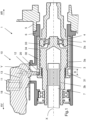
- the Figures 1 to 5 illustrate a transmission system 1 according to a first embodiment of the invention.
- the transmission system 1 is here a connecting clutch between two shafts 2, 3 which is used, in a transmission chain of a vehicle, to transmit a torque coming from a thermal or electric engine, not illustrated, to a wheel shaft 7 of a motor vehicle.
- a transmission system can, for example, be part of a secondary transmission chain capable of transmitting a torque from a secondary engine of the vehicle, such as an electric motor, to a rear or front axle of a vehicle while a primary transmission chain is capable of transmitting a torque from a main engine, for example a thermal engine, to the wheel shafts of another axle of the vehicle.
- a main engine for example a thermal engine
- the transmission system 1 is kinematically interposed between a speed reducer 5 and the wheel shaft 7 of the vehicle.
- the output shaft of the speed reducer is called the drive shaft 2.
- the drive shaft 2 of the transmission system 1 comprises a first external spline 2a machined on its end.
- the transmission system 1 also comprises a driven shaft 3 for transmission coaxial with the driving shaft 2 comprising a second external spline 3a.
- the driven shaft 3 is inserted into the driving shaft 2 and guided in rotation by means of a guide bearing 4.
- the driven shaft 3 for transmission comprises an internal torque output spline 3b linked in rotation with the wheel shaft 7 of the vehicle.
- the receiving part 30 moves axially between two extreme positions when the output shaft pivots about its axis of rotation Y.
- the receiving part 30 is an axial slider having a shape of revolution, the axial slider 30 comprising at least a first internal connection groove 33 arranged to rotate the driving shaft 2 and a second internal connection groove 34 arranged to rotate the driven shaft 3.
- the first and second internal grooves 33, 34 are engaged respectively in the first external groove 2a of the driving shaft and the second external groove 3a of the driven shaft when the receiving part 30 is in one of the two extreme positions of the receiving part 30, this extreme position being called the second extreme coupling position.
- the second internal connection spline 34 is disengaged from the second external spline 3a of the driven shaft 3 when the receiving part 30 is in a first extreme uncoupling position.
- the axial slider 30 moves axially by a value Dx relative to the driven transmission shaft 3 which is axially fixed.
- the second internal spline 34 for connecting the axial sliding gear is made in the form of a series of internal splines spaced axially at a regular pitch, for example five internal splines spaced axially at a pitch of between 3 and 15 mm.
- the second external spline 3a of the driven shaft 3 is also made in the form of a series of internal splines spaced axially at the same regular pitch.
- the actuating cam 20 is fixed at the end of the output shaft 12, for example force-fitted.
- the actuating cam 20 comprises a connecting orifice 24, the output shaft 12 being inserted into this connecting orifice.
- the rotation of the actuating cam 20 about the rotation axis Y causes the receiving part 30 to move.
- the receiving part 30 is a part of revolution about the main axis X.
- the receiving part 30 is rotated by the drive shaft 2 via the internal spline 33 which meshes with the first external spline 2a. Since the receiving housing 31 is made in the form of an annular groove, a relative rotational movement along the main axis X between the receiving part 30 and the actuating cam 20 is possible.
- the actuating cam 20 is received directly in the receiving part 30.
- the actuating cam can be received in an intermediate component kinematically linked to the receiving part.
- the actuating cam 20 has two contact zones 20a, 20b bearing on the parallel surfaces 32 of the receiving housing, the bearing width L along the main axis X separating the two contact zones is constant over the entire rotation of the output shaft. To guarantee a clearance of the actuating cam 20 within the annular groove without untimely friction, an operating clearance is defined between the bearing width L of the actuating cam and the distance D axially separating along the main axis X the two parallel surfaces 32 of the receiving housing.
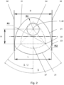
- the actuating cam 20 comprises three actuating faces 21 made in the form of a cylinder portion, the three cylinder portion centers 22 form an isosceles triangle, the main vertex of the isosceles triangle being coincident with the axis of rotation Y of the output shaft.
- the geometry of the contact zones 20a, 20b of the actuating cam uses large-diameter cylinder portions making it possible to reduce the contact pressure with the parallel surfaces of the receiving housing.
- the actuating cam rotates, the actuating face 21 slides on one of the parallel surfaces 32.
- the actuating cam 20 has a symmetrical actuating profile whose axis of symmetry passes through the bisector 37 of the isosceles triangle, the bisector of the isosceles triangle corresponding to the middle of the second angular sector ⁇ 2.
- the isosceles triangle has a main angle ⁇ for example between 45° and 150°.
- the actuating cam 20 thus has a symmetrical profile passing through the axis of rotation Y.
- the operating clearance between the support width L of the actuating cam and the distance D is constant over the entire rotation of the output shaft.
- the operating clearance is of the order of 0.1 mm to 0.6 mm. The actuation precision is thus improved.
- the actuating faces 21 of the actuating cam 20 are connected to each other by a cylindrical connecting face 23 with a radius R2 smaller than the radius R1 of the cylinder portions, the connecting radius being between 1 and 5 mm.
- the cylindrical connecting face 23 is also caused to slide on one of the parallel surfaces 32.
- the contact zones 20a, 20b of the actuating cam are alternately formed by an actuating face 21 and/or a cylindrical connecting face 23.
- the geometry of the contact zone 20a, 20b then has a radius R1 or a radius R2.
- the actuating cam 20 also comprises an end radius R3 arranged to interact with the parallel surfaces 32 of the receiving part 30 and tangentially connecting two actuating faces 21, the center of this end radius R3 being concentric with the axis of rotation Y.
- the center of the end radius R3 passes through the bisector 37 of the isosceles triangle.
- the dimension of the radius R3 is defined so as to respect the support width L.
- the end radius R3 is greater than the radius R2 of the cylindrical bond faces.
- the main axis X of the receiving part 30 is non-intersecting with the axis of rotation Y.
- the axis of rotation Y is offset relative to a plane parallel to the axis of rotation Y and passing through the main axis X by a value of a few millimeters.
- This actuating device 10 also comprises a protective housing 18 which protects the electric motor 11 and supports the speed reduction device 13.
- the protective housing 18 is attached to a protective sleeve 6 of the transmission system 1.
- the protective sleeve 6 is in the form of a cylinder with an axis coincident with the main axis X and comprises an orifice for the passage of the output shaft 12 of the actuating device.
- the axis of the passage orifice is perpendicular to the main axis X.
- the protective sleeve 6 is attached to the casing of the speed reducer 5.
- the output shaft 12 is arranged to pivot according to three adjacent angular sectors ⁇ 1, ⁇ 2, ⁇ 3, a first angular sector ⁇ 1, a second angular sector ⁇ 2 which is adjacent to the first angular sector ⁇ 1, a third angular sector ⁇ 3 which is adjacent to the second angular sector ⁇ 2.
- the receiving part 30 is in the first extreme uncoupling position.
- the receiving part 30 remains axially stationary in the first extreme position when the rotation of the output shaft is located in the first angular sector.
- the angle value of the first angular sector ⁇ 1 is 15°.
- the receiving part 30 remains in a stable position which makes it possible to cut off the electrical power supply within the actuating device, thereby reducing the electrical consumption of the vehicle.
- the receiving part 30 moves axially between the two extreme uncoupling and coupling positions when the output shaft 12 pivots along the entire second angular sector ⁇ 2.
- the displacement Dx of the receiving part 30 is visible on the figure 5 .
- the angle value of the second angular sector ⁇ 2 is approximately 100°. This low angle value, less than 180°, allows the actuation time to be reduced.
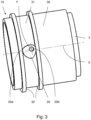
- the figure 3 illustrates the position of the actuating cam 20 in the first extreme uncoupling position.
- the axial slider 30 is positioned axially by means of the actuating faces 21 of the actuating cam 20 which are flush with the parallel surfaces 32 of the receiving housing 31.
- the figure 4 illustrates the position of the actuating cam 20 in the second extreme coupling position.
- the receiving part 30 remains axially immobile in the second extreme position when the rotation of the output shaft is located in the third angular sector ⁇ 3.
- the angle value of the third angular sector ⁇ 3 is approximately 5°.
- the receiving part 30 remains in a stable position which makes it possible to cut off the power supply within the actuating device, thus reducing the electrical consumption of the vehicle.
- the support width L along the main axis X separating the two contact zones 20a, 20b is constant over the three angular sectors ⁇ 1, ⁇ 2, ⁇ 3 of rotation of the output shaft.
- figure 5 illustrates the different angular positions taken by the actuating cam 20 during the movement Dx of the receiving part 30.
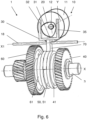
- FIG 6 is a perspective view of a transmission system 1 corresponding to a part of a speed reducer.
- the speed reducer may for example be intended to equip an electric motor vehicle for which the gear ratio change is done automatically.
- the selection of the gear ratio between a first gear and a second gear is carried out by an actuating device 10 according to the invention.
- the actuating device 10 is configured to select a speed ratio by means of the actuating fork 70.
- the actuating fork 70 makes it possible to slide a dog clutch sleeve 50 along the main axis X so as to secure a driven transmission shaft 3 with a first or second idler gears 40, 60.
- Such cooperation between the dog clutch sleeve 50 and one or other of the first and second idler gears 40, 60 occurs when there is an angular coincidence between the teeth of these two elements.
- the idler gear 40 of the first gear and the idler gear 60 of the second gear each comprise a dog-engaging spline 41, 61 arranged around the main axis X capable of cooperating with the dog-engaging sleeve 50.
- the idler gear 40 of the first gear and the idler gear 60 of the second gear are rotatably mounted around the driven shaft 3 of the transmission and the dog-engaging sleeve 50 is mounted integral in rotation with the driven shaft 3, for example by means of an internal spline 51.
- the sleeve dog clutch 50 comprises, for example, dog clutch teeth at its two axial ends in continuity with the internal groove 51.
- the dog clutch sleeve 50 can be kept spaced from the first idler gear 40 of the first gear and from the second idler gear 60 of the second gear in a neutral position, for which no torque is transmitted between the input shaft of the speed reducer and the driven transmission shaft 3 because none of the idler gears 40 and 60 cooperate with the dog clutch sleeve 50.
- the neutral position corresponds to a disconnection mode in which the electric machine no longer transmits torque to the wheels of the vehicle.
- the dog clutch sleeve 50 is here arranged between the first idler gear 40 and the second idler gear 60, arms of the actuating fork 70 also being arranged between these two idler gears 40, 60.
- Each first gear 40 and second gear 60 corresponds to a ratio of the speed reducer, for example with a first speed ratio for the first gear 40 and a second speed ratio for the second gear 60.
- the actuating fork 70 can move laterally so as to perform dog clutch engagement of the dog clutch sleeve 50 with either the first idler gear 40 or the second idler gear 60.
- the actuating fork 70 has arms which are inserted into an annular groove in the dog clutch sleeve 50.
- the actuating fork 70 slides axially along a control rod 18.
- This control rod 18 extends along a secondary axis X1 and corresponds for example to a solid cylinder.
- the receiving part 30 moves axially between two extreme positions when the output shaft pivots about its axis of rotation Y.
- the receiving part 30 is a control member secured to the actuating fork 70 and which slides along the secondary axis X1 of the control rod 18, such that when the receiving part 30 is in a first extreme coupling position, a torque is transmitted between the first idler gear 40 and the driven transmission shaft 3, when the receiving part 30 is in a second extreme coupling position, a torque is transmitted between the second idler gear 60 and the driven transmission shaft 3.
- the dog clutch sleeve 50 is in an intermediate uncoupling position, otherwise called neutral position, when the angular position of the output shaft 12 is located at half of the second angular sector ⁇ 2.
- control member 30 has a U-shaped receiving housing 31 comprising two actuating arms 35 supporting the parallel surfaces 32 separated along the main axis X by a distance D.
- the output shaft 12 is arranged to pivot according to three adjacent angular sectors ⁇ 1, ⁇ 2, ⁇ 3, a first angular sector ⁇ 1, a second angular sector ⁇ 2 which is adjacent to the first angular sector ⁇ 1, a third angular sector ⁇ 3 which is adjacent to the second angular sector ⁇ 2.
- the control member 30 is in the first extreme coupling position in which the first gear ratio is engaged.
- the actuating fork 70 remains axially stationary in the first extreme position when the rotation of the output shaft is in the first angular sector.
- the angle value of the first angular sector ⁇ 1 is 5°.
- the control member 30 remains in a stable position which makes it possible to cut off the electrical power supply within the actuating device, thereby reducing the electrical consumption of the vehicle.
- the control member 30 moves axially between the two extreme coupling positions when the output shaft 12 pivots along the entire second angular sector ⁇ 2.
- the angle value of the second angular sector ⁇ 2 is approximately 120°. This low angle value, less than 180°, makes it possible to reduce the actuation time.
- the control member 30 is in the second extreme coupling position in which the second speed ratio is engaged.
- the actuating fork 70 remains axially stationary in the second extreme actuating position when the rotation of the output shaft is located in the third angular sector ⁇ 3.
- the angle value of the third angular sector ⁇ 3 is identical to the angle value of the first angular sector ⁇ 1.
- the control member 30 also remains in a stable position.
- an operating clearance is defined between the bearing width L of the actuating cam and the distance D axially separating along the main axis X the two parallel surfaces 32 of the receiving housing. Thanks to the particular geometry of the profile of the actuating cam 20, the bearing width L along the main axis X separating the two contact zones 20a, 20b is constant over the three angular sectors ⁇ 1, ⁇ 2, ⁇ 3 of rotation of the output shaft.
- Another advantage of the invention is to improve the reliability of the electric motor.
- the rotation of the output shaft 12 is done under low torque since in the first angular sector ⁇ 1 or the third angular sector ⁇ 3, the contact zone 20a, 20b of the actuating cam 20 is tangent to the surface 32 of the receiving housing. There is therefore no resistive torque, which allows the rotation of the electric machine under low torque.
Landscapes
- Engineering & Computer Science (AREA)
- General Engineering & Computer Science (AREA)
- Mechanical Engineering (AREA)
- Mechanical Operated Clutches (AREA)
- Gear-Shifting Mechanisms (AREA)
- Structure Of Transmissions (AREA)
- Transmission Devices (AREA)
Applications Claiming Priority (1)
| Application Number | Priority Date | Filing Date | Title |
|---|---|---|---|
| FR2303933A FR3148065A1 (fr) | 2023-04-19 | 2023-04-19 | Dispositif d’actionnement pour système de transmission |
Publications (2)
| Publication Number | Publication Date |
|---|---|
| EP4455518A1 true EP4455518A1 (de) | 2024-10-30 |
| EP4455518B1 EP4455518B1 (de) | 2025-11-26 |
Family
ID=87280596
Family Applications (1)
| Application Number | Title | Priority Date | Filing Date |
|---|---|---|---|
| EP24170352.9A Active EP4455518B1 (de) | 2023-04-19 | 2024-04-15 | Betätigungsvorrichtung für ein getriebesystem |
Country Status (4)
| Country | Link |
|---|---|
| US (1) | US12460720B2 (de) |
| EP (1) | EP4455518B1 (de) |
| CN (1) | CN118815921A (de) |
| FR (1) | FR3148065A1 (de) |
Families Citing this family (2)
| Publication number | Priority date | Publication date | Assignee | Title |
|---|---|---|---|---|
| US12304493B2 (en) * | 2023-03-21 | 2025-05-20 | GM Global Technology Operations LLC | Control of transitions between transmission states |
| CN119554341A (zh) * | 2023-09-01 | 2025-03-04 | 法雷奥离合器公司 | 断开单元、车辆的动力传动系统、车辆的同步机构以及车辆 |
Citations (4)
| Publication number | Priority date | Publication date | Assignee | Title |
|---|---|---|---|---|
| FR2485674A1 (fr) * | 1980-06-24 | 1981-12-31 | Thomson Csf | Dispositif de commande du deplacement d'une piece et imprimante comportant un tel dispositif |
| US4428248A (en) * | 1981-04-20 | 1984-01-31 | Eaton Corporation | Shifting actuator |
| EP1520127A1 (de) | 2002-07-05 | 2005-04-06 | ZF FRIEDRICHSHAFEN Aktiengesellschaft | Getriebeschaltung |
| DE102021209053A1 (de) * | 2021-08-18 | 2023-02-23 | Zf Friedrichshafen Ag | Betätigungsvorrichtung für ein Getriebeelement |
Family Cites Families (1)
| Publication number | Priority date | Publication date | Assignee | Title |
|---|---|---|---|---|
| US3368638A (en) * | 1965-08-04 | 1968-02-13 | Eaton Yale & Towne | Tandem axle change speed control system |
-
2023
- 2023-04-19 FR FR2303933A patent/FR3148065A1/fr active Pending
-
2024
- 2024-04-15 EP EP24170352.9A patent/EP4455518B1/de active Active
- 2024-04-18 CN CN202410466646.2A patent/CN118815921A/zh active Pending
- 2024-04-19 US US18/640,226 patent/US12460720B2/en active Active
Patent Citations (4)
| Publication number | Priority date | Publication date | Assignee | Title |
|---|---|---|---|---|
| FR2485674A1 (fr) * | 1980-06-24 | 1981-12-31 | Thomson Csf | Dispositif de commande du deplacement d'une piece et imprimante comportant un tel dispositif |
| US4428248A (en) * | 1981-04-20 | 1984-01-31 | Eaton Corporation | Shifting actuator |
| EP1520127A1 (de) | 2002-07-05 | 2005-04-06 | ZF FRIEDRICHSHAFEN Aktiengesellschaft | Getriebeschaltung |
| DE102021209053A1 (de) * | 2021-08-18 | 2023-02-23 | Zf Friedrichshafen Ag | Betätigungsvorrichtung für ein Getriebeelement |
Also Published As
| Publication number | Publication date |
|---|---|
| FR3148065A1 (fr) | 2024-10-25 |
| CN118815921A (zh) | 2024-10-22 |
| US20240353003A1 (en) | 2024-10-24 |
| US12460720B2 (en) | 2025-11-04 |
| EP4455518B1 (de) | 2025-11-26 |
Similar Documents
| Publication | Publication Date | Title |
|---|---|---|
| EP4455518B1 (de) | Betätigungsvorrichtung für ein getriebesystem | |
| FR2838169A1 (fr) | Systeme de debrayage pour un mecanisme a deux embrayages pour vehicule automobile. | |
| EP3959449A1 (de) | Getriebegehäuse und radfahrzeug mit einem solchen getriebegehäuse | |
| WO1999002855A1 (fr) | Dispositif de frein de la rotation relative de deux elements | |
| FR2770599A1 (fr) | Boite de vitesses avec marche arriere synchronisee pour vehicules automobiles | |
| EP4185500B1 (de) | Getriebe und mit einem solchen getriebe ausgestattetes kraftfahrzeug | |
| EP0488857A1 (de) | Interne Steuervorrichtung für Schaltgetriebe | |
| EP0643239B1 (de) | Getriebe mit eingebauter Kupplung | |
| FR2959544A1 (fr) | Dispositif de synchronisation pour boite de vitesses et boite de vitesses le comportant | |
| FR3056160B1 (fr) | Transmission pour vehicule automobile a propulsion electrique | |
| EP2909509B1 (de) | Differentialvorrichtung für ein motorisiertes radfahrzeug | |
| WO2026087429A1 (fr) | Système d'accouplement d'arbres de transmission | |
| WO2026087428A1 (fr) | Système d'accouplement d'arbres de transmission et procédé de commande d'un tel système d'accouplement d'arbres de transmission | |
| FR3160745A1 (fr) | Arbre de sortie de couple et dispositif d’actionnement pour système de transmission | |
| FR3124239A1 (fr) | Dispositif d’actionnement électromagnétique et système de transmission équipé de ce dispositif d’actionnement électromagnétique | |
| EP4055300B1 (de) | Rollenlaufwerkselement | |
| WO2026087426A1 (fr) | Système d'accouplement d'arbres de transmission | |
| EP0333539B1 (de) | Lösbarer Linearschrittmotor mit einem rückzentrierten Läufer | |
| FR3155168A1 (fr) | Dispositif d’actionnement pour système de transmission | |
| EP4596919A1 (de) | Auskuppelbare getriebevorrichtung und landwirtschaftliche maschine mit solcher vorrichtung | |
| EP1538051A1 (de) | Notbetätigungseinrichtung für eine elektromechanische Betriebsbremse | |
| FR2888626A1 (fr) | Synchroniseur de vehicule automobile | |
| FR2709795A1 (fr) | Dispositif d'entraînement non permanent pour mécanisme réducteur de transmission. | |
| FR2682647A1 (fr) | Dispositif d'entrainement debrayable pour roues non motrices de vehicule automobile. | |
| EP4678445A1 (de) | Differentialmodul |
Legal Events
| Date | Code | Title | Description |
|---|---|---|---|
| PUAI | Public reference made under article 153(3) epc to a published international application that has entered the european phase |
Free format text: ORIGINAL CODE: 0009012 |
|
| STAA | Information on the status of an ep patent application or granted ep patent |
Free format text: STATUS: REQUEST FOR EXAMINATION WAS MADE |
|
| STAA | Information on the status of an ep patent application or granted ep patent |
Free format text: STATUS: EXAMINATION IS IN PROGRESS |
|
| 17P | Request for examination filed |
Effective date: 20240415 |
|
| AK | Designated contracting states |
Kind code of ref document: A1 Designated state(s): AL AT BE BG CH CY CZ DE DK EE ES FI FR GB GR HR HU IE IS IT LI LT LU LV MC ME MK MT NL NO PL PT RO RS SE SI SK SM TR |
|
| 17Q | First examination report despatched |
Effective date: 20241011 |
|
| GRAP | Despatch of communication of intention to grant a patent |
Free format text: ORIGINAL CODE: EPIDOSNIGR1 |
|
| RIC1 | Information provided on ipc code assigned before grant |
Ipc: F16H 63/32 20060101ALN20250516BHEP Ipc: F16H 61/32 20060101ALN20250516BHEP Ipc: F16H 61/28 20060101ALN20250516BHEP Ipc: F16H 63/30 20060101AFI20250516BHEP |
|
| STAA | Information on the status of an ep patent application or granted ep patent |
Free format text: STATUS: GRANT OF PATENT IS INTENDED |
|
| INTG | Intention to grant announced |
Effective date: 20250626 |
|
| GRAS | Grant fee paid |
Free format text: ORIGINAL CODE: EPIDOSNIGR3 |
|
| GRAA | (expected) grant |
Free format text: ORIGINAL CODE: 0009210 |
|
| STAA | Information on the status of an ep patent application or granted ep patent |
Free format text: STATUS: THE PATENT HAS BEEN GRANTED |
|
| AK | Designated contracting states |
Kind code of ref document: B1 Designated state(s): AL AT BE BG CH CY CZ DE DK EE ES FI FR GB GR HR HU IE IS IT LI LT LU LV MC ME MK MT NL NO PL PT RO RS SE SI SK SM TR |
|
| REG | Reference to a national code |
Ref country code: CH Ref legal event code: F10 Free format text: ST27 STATUS EVENT CODE: U-0-0-F10-F00 (AS PROVIDED BY THE NATIONAL OFFICE) Effective date: 20251126 Ref country code: GB Ref legal event code: FG4D Free format text: NOT ENGLISH |
|
| REG | Reference to a national code |
Ref country code: IE Ref legal event code: FG4D Free format text: LANGUAGE OF EP DOCUMENT: FRENCH |
|
| REG | Reference to a national code |
Ref country code: DE Ref legal event code: R096 Ref document number: 602024001383 Country of ref document: DE |
|
| REG | Reference to a national code |
Ref country code: NL Ref legal event code: MP Effective date: 20251126 |
|
| PG25 | Lapsed in a contracting state [announced via postgrant information from national office to epo] |
Ref country code: ES Free format text: LAPSE BECAUSE OF FAILURE TO SUBMIT A TRANSLATION OF THE DESCRIPTION OR TO PAY THE FEE WITHIN THE PRESCRIBED TIME-LIMIT Effective date: 20251126 |
|
| REG | Reference to a national code |
Ref country code: LT Ref legal event code: MG9D |
|
| PG25 | Lapsed in a contracting state [announced via postgrant information from national office to epo] |
Ref country code: NO Free format text: LAPSE BECAUSE OF FAILURE TO SUBMIT A TRANSLATION OF THE DESCRIPTION OR TO PAY THE FEE WITHIN THE PRESCRIBED TIME-LIMIT Effective date: 20260226 |
|
| PG25 | Lapsed in a contracting state [announced via postgrant information from national office to epo] |
Ref country code: FI Free format text: LAPSE BECAUSE OF FAILURE TO SUBMIT A TRANSLATION OF THE DESCRIPTION OR TO PAY THE FEE WITHIN THE PRESCRIBED TIME-LIMIT Effective date: 20251126 Ref country code: AT Free format text: LAPSE BECAUSE OF FAILURE TO SUBMIT A TRANSLATION OF THE DESCRIPTION OR TO PAY THE FEE WITHIN THE PRESCRIBED TIME-LIMIT Effective date: 20251126 Ref country code: HR Free format text: LAPSE BECAUSE OF FAILURE TO SUBMIT A TRANSLATION OF THE DESCRIPTION OR TO PAY THE FEE WITHIN THE PRESCRIBED TIME-LIMIT Effective date: 20251126 |
|
| REG | Reference to a national code |
Ref country code: AT Ref legal event code: MK05 Ref document number: 1861338 Country of ref document: AT Kind code of ref document: T Effective date: 20251126 |
|
| PG25 | Lapsed in a contracting state [announced via postgrant information from national office to epo] |
Ref country code: NL Free format text: LAPSE BECAUSE OF FAILURE TO SUBMIT A TRANSLATION OF THE DESCRIPTION OR TO PAY THE FEE WITHIN THE PRESCRIBED TIME-LIMIT Effective date: 20251126 |
|
| PG25 | Lapsed in a contracting state [announced via postgrant information from national office to epo] |
Ref country code: RS Free format text: LAPSE BECAUSE OF FAILURE TO SUBMIT A TRANSLATION OF THE DESCRIPTION OR TO PAY THE FEE WITHIN THE PRESCRIBED TIME-LIMIT Effective date: 20260226 |
|
| PG25 | Lapsed in a contracting state [announced via postgrant information from national office to epo] |
Ref country code: IS Free format text: LAPSE BECAUSE OF FAILURE TO SUBMIT A TRANSLATION OF THE DESCRIPTION OR TO PAY THE FEE WITHIN THE PRESCRIBED TIME-LIMIT Effective date: 20260326 |
|
| PG25 | Lapsed in a contracting state [announced via postgrant information from national office to epo] |
Ref country code: PT Free format text: LAPSE BECAUSE OF FAILURE TO SUBMIT A TRANSLATION OF THE DESCRIPTION OR TO PAY THE FEE WITHIN THE PRESCRIBED TIME-LIMIT Effective date: 20260326 |
|
| PG25 | Lapsed in a contracting state [announced via postgrant information from national office to epo] |
Ref country code: PL Free format text: LAPSE BECAUSE OF FAILURE TO SUBMIT A TRANSLATION OF THE DESCRIPTION OR TO PAY THE FEE WITHIN THE PRESCRIBED TIME-LIMIT Effective date: 20251126 |
|
| PG25 | Lapsed in a contracting state [announced via postgrant information from national office to epo] |
Ref country code: LV Free format text: LAPSE BECAUSE OF FAILURE TO SUBMIT A TRANSLATION OF THE DESCRIPTION OR TO PAY THE FEE WITHIN THE PRESCRIBED TIME-LIMIT Effective date: 20251126 |