EP4455474A1 - Engine and engine control method - Google Patents
Engine and engine control method Download PDFInfo
- Publication number
- EP4455474A1 EP4455474A1 EP23752788.2A EP23752788A EP4455474A1 EP 4455474 A1 EP4455474 A1 EP 4455474A1 EP 23752788 A EP23752788 A EP 23752788A EP 4455474 A1 EP4455474 A1 EP 4455474A1
- Authority
- EP
- European Patent Office
- Prior art keywords
- fuel
- line
- combustion chamber
- intake
- engine
- Prior art date
- Legal status (The legal status is an assumption and is not a legal conclusion. Google has not performed a legal analysis and makes no representation as to the accuracy of the status listed.)
- Granted
Links
Images




Classifications
-
- F—MECHANICAL ENGINEERING; LIGHTING; HEATING; WEAPONS; BLASTING
- F02—COMBUSTION ENGINES; HOT-GAS OR COMBUSTION-PRODUCT ENGINE PLANTS
- F02D—CONTROLLING COMBUSTION ENGINES
- F02D19/00—Controlling engines characterised by their use of non-liquid fuels, pluralities of fuels, or non-fuel substances added to the combustible mixtures
- F02D19/02—Controlling engines characterised by their use of non-liquid fuels, pluralities of fuels, or non-fuel substances added to the combustible mixtures peculiar to engines working with gaseous fuels
- F02D19/021—Control of components of the fuel supply system
- F02D19/023—Control of components of the fuel supply system to adjust the fuel mass or volume flow
-
- F—MECHANICAL ENGINEERING; LIGHTING; HEATING; WEAPONS; BLASTING
- F02—COMBUSTION ENGINES; HOT-GAS OR COMBUSTION-PRODUCT ENGINE PLANTS
- F02M—SUPPLYING COMBUSTION ENGINES IN GENERAL WITH COMBUSTIBLE MIXTURES OR CONSTITUENTS THEREOF
- F02M21/00—Apparatus for supplying engines with non-liquid fuels, e.g. gaseous fuels stored in liquid form
- F02M21/02—Apparatus for supplying engines with non-liquid fuels, e.g. gaseous fuels stored in liquid form for gaseous fuels
-
- F—MECHANICAL ENGINEERING; LIGHTING; HEATING; WEAPONS; BLASTING
- F02—COMBUSTION ENGINES; HOT-GAS OR COMBUSTION-PRODUCT ENGINE PLANTS
- F02D—CONTROLLING COMBUSTION ENGINES
- F02D19/00—Controlling engines characterised by their use of non-liquid fuels, pluralities of fuels, or non-fuel substances added to the combustible mixtures
- F02D19/06—Controlling engines characterised by their use of non-liquid fuels, pluralities of fuels, or non-fuel substances added to the combustible mixtures peculiar to engines working with pluralities of fuels, e.g. alternatively with light and heavy fuel oil, other than engines indifferent to the fuel consumed
- F02D19/0602—Control of components of the fuel supply system
- F02D19/0607—Control of components of the fuel supply system to adjust the fuel mass or volume flow
-
- F—MECHANICAL ENGINEERING; LIGHTING; HEATING; WEAPONS; BLASTING
- F02—COMBUSTION ENGINES; HOT-GAS OR COMBUSTION-PRODUCT ENGINE PLANTS
- F02D—CONTROLLING COMBUSTION ENGINES
- F02D19/00—Controlling engines characterised by their use of non-liquid fuels, pluralities of fuels, or non-fuel substances added to the combustible mixtures
- F02D19/06—Controlling engines characterised by their use of non-liquid fuels, pluralities of fuels, or non-fuel substances added to the combustible mixtures peculiar to engines working with pluralities of fuels, e.g. alternatively with light and heavy fuel oil, other than engines indifferent to the fuel consumed
- F02D19/0639—Controlling engines characterised by their use of non-liquid fuels, pluralities of fuels, or non-fuel substances added to the combustible mixtures peculiar to engines working with pluralities of fuels, e.g. alternatively with light and heavy fuel oil, other than engines indifferent to the fuel consumed characterised by the type of fuels
- F02D19/0642—Controlling engines characterised by their use of non-liquid fuels, pluralities of fuels, or non-fuel substances added to the combustible mixtures peculiar to engines working with pluralities of fuels, e.g. alternatively with light and heavy fuel oil, other than engines indifferent to the fuel consumed characterised by the type of fuels at least one fuel being gaseous, the other fuels being gaseous or liquid at standard conditions
- F02D19/0644—Controlling engines characterised by their use of non-liquid fuels, pluralities of fuels, or non-fuel substances added to the combustible mixtures peculiar to engines working with pluralities of fuels, e.g. alternatively with light and heavy fuel oil, other than engines indifferent to the fuel consumed characterised by the type of fuels at least one fuel being gaseous, the other fuels being gaseous or liquid at standard conditions the gaseous fuel being hydrogen, ammonia or carbon monoxide
-
- F—MECHANICAL ENGINEERING; LIGHTING; HEATING; WEAPONS; BLASTING
- F02—COMBUSTION ENGINES; HOT-GAS OR COMBUSTION-PRODUCT ENGINE PLANTS
- F02D—CONTROLLING COMBUSTION ENGINES
- F02D19/00—Controlling engines characterised by their use of non-liquid fuels, pluralities of fuels, or non-fuel substances added to the combustible mixtures
- F02D19/06—Controlling engines characterised by their use of non-liquid fuels, pluralities of fuels, or non-fuel substances added to the combustible mixtures peculiar to engines working with pluralities of fuels, e.g. alternatively with light and heavy fuel oil, other than engines indifferent to the fuel consumed
- F02D19/0639—Controlling engines characterised by their use of non-liquid fuels, pluralities of fuels, or non-fuel substances added to the combustible mixtures peculiar to engines working with pluralities of fuels, e.g. alternatively with light and heavy fuel oil, other than engines indifferent to the fuel consumed characterised by the type of fuels
- F02D19/0642—Controlling engines characterised by their use of non-liquid fuels, pluralities of fuels, or non-fuel substances added to the combustible mixtures peculiar to engines working with pluralities of fuels, e.g. alternatively with light and heavy fuel oil, other than engines indifferent to the fuel consumed characterised by the type of fuels at least one fuel being gaseous, the other fuels being gaseous or liquid at standard conditions
- F02D19/0647—Controlling engines characterised by their use of non-liquid fuels, pluralities of fuels, or non-fuel substances added to the combustible mixtures peculiar to engines working with pluralities of fuels, e.g. alternatively with light and heavy fuel oil, other than engines indifferent to the fuel consumed characterised by the type of fuels at least one fuel being gaseous, the other fuels being gaseous or liquid at standard conditions the gaseous fuel being liquefied petroleum gas [LPG], liquefied natural gas [LNG], compressed natural gas [CNG] or dimethyl ether [DME]
-
- F—MECHANICAL ENGINEERING; LIGHTING; HEATING; WEAPONS; BLASTING
- F02—COMBUSTION ENGINES; HOT-GAS OR COMBUSTION-PRODUCT ENGINE PLANTS
- F02D—CONTROLLING COMBUSTION ENGINES
- F02D19/00—Controlling engines characterised by their use of non-liquid fuels, pluralities of fuels, or non-fuel substances added to the combustible mixtures
- F02D19/06—Controlling engines characterised by their use of non-liquid fuels, pluralities of fuels, or non-fuel substances added to the combustible mixtures peculiar to engines working with pluralities of fuels, e.g. alternatively with light and heavy fuel oil, other than engines indifferent to the fuel consumed
- F02D19/0663—Details on the fuel supply system, e.g. tanks, valves, pipes, pumps, rails, injectors or mixers
- F02D19/0686—Injectors
- F02D19/0692—Arrangement of multiple injectors per combustion chamber
-
- F—MECHANICAL ENGINEERING; LIGHTING; HEATING; WEAPONS; BLASTING
- F02—COMBUSTION ENGINES; HOT-GAS OR COMBUSTION-PRODUCT ENGINE PLANTS
- F02D—CONTROLLING COMBUSTION ENGINES
- F02D19/00—Controlling engines characterised by their use of non-liquid fuels, pluralities of fuels, or non-fuel substances added to the combustible mixtures
- F02D19/06—Controlling engines characterised by their use of non-liquid fuels, pluralities of fuels, or non-fuel substances added to the combustible mixtures peculiar to engines working with pluralities of fuels, e.g. alternatively with light and heavy fuel oil, other than engines indifferent to the fuel consumed
- F02D19/08—Controlling engines characterised by their use of non-liquid fuels, pluralities of fuels, or non-fuel substances added to the combustible mixtures peculiar to engines working with pluralities of fuels, e.g. alternatively with light and heavy fuel oil, other than engines indifferent to the fuel consumed simultaneously using pluralities of fuels
- F02D19/081—Adjusting the fuel composition or mixing ratio; Transitioning from one fuel to the other
-
- F—MECHANICAL ENGINEERING; LIGHTING; HEATING; WEAPONS; BLASTING
- F02—COMBUSTION ENGINES; HOT-GAS OR COMBUSTION-PRODUCT ENGINE PLANTS
- F02D—CONTROLLING COMBUSTION ENGINES
- F02D41/00—Electrical control of supply of combustible mixture or its constituents
- F02D41/0025—Controlling engines characterised by use of non-liquid fuels, pluralities of fuels, or non-fuel substances added to the combustible mixtures
-
- F—MECHANICAL ENGINEERING; LIGHTING; HEATING; WEAPONS; BLASTING
- F02—COMBUSTION ENGINES; HOT-GAS OR COMBUSTION-PRODUCT ENGINE PLANTS
- F02D—CONTROLLING COMBUSTION ENGINES
- F02D41/00—Electrical control of supply of combustible mixture or its constituents
- F02D41/0025—Controlling engines characterised by use of non-liquid fuels, pluralities of fuels, or non-fuel substances added to the combustible mixtures
- F02D41/0027—Controlling engines characterised by use of non-liquid fuels, pluralities of fuels, or non-fuel substances added to the combustible mixtures the fuel being gaseous
-
- F—MECHANICAL ENGINEERING; LIGHTING; HEATING; WEAPONS; BLASTING
- F02—COMBUSTION ENGINES; HOT-GAS OR COMBUSTION-PRODUCT ENGINE PLANTS
- F02D—CONTROLLING COMBUSTION ENGINES
- F02D41/00—Electrical control of supply of combustible mixture or its constituents
- F02D41/30—Controlling fuel injection
- F02D41/3094—Controlling fuel injection the fuel injection being effected by at least two different injectors, e.g. one in the intake manifold and one in the cylinder
-
- F—MECHANICAL ENGINEERING; LIGHTING; HEATING; WEAPONS; BLASTING
- F02—COMBUSTION ENGINES; HOT-GAS OR COMBUSTION-PRODUCT ENGINE PLANTS
- F02D—CONTROLLING COMBUSTION ENGINES
- F02D41/00—Electrical control of supply of combustible mixture or its constituents
- F02D41/30—Controlling fuel injection
- F02D41/32—Controlling fuel injection of the low pressure type
- F02D41/34—Controlling fuel injection of the low pressure type with means for controlling injection timing or duration
- F02D41/345—Controlling injection timing
-
- F—MECHANICAL ENGINEERING; LIGHTING; HEATING; WEAPONS; BLASTING
- F02—COMBUSTION ENGINES; HOT-GAS OR COMBUSTION-PRODUCT ENGINE PLANTS
- F02M—SUPPLYING COMBUSTION ENGINES IN GENERAL WITH COMBUSTIBLE MIXTURES OR CONSTITUENTS THEREOF
- F02M21/00—Apparatus for supplying engines with non-liquid fuels, e.g. gaseous fuels stored in liquid form
- F02M21/02—Apparatus for supplying engines with non-liquid fuels, e.g. gaseous fuels stored in liquid form for gaseous fuels
- F02M21/0203—Apparatus for supplying engines with non-liquid fuels, e.g. gaseous fuels stored in liquid form for gaseous fuels characterised by the type of gaseous fuel
- F02M21/0206—Non-hydrocarbon fuels, e.g. hydrogen, ammonia or carbon monoxide
-
- F—MECHANICAL ENGINEERING; LIGHTING; HEATING; WEAPONS; BLASTING
- F02—COMBUSTION ENGINES; HOT-GAS OR COMBUSTION-PRODUCT ENGINE PLANTS
- F02M—SUPPLYING COMBUSTION ENGINES IN GENERAL WITH COMBUSTIBLE MIXTURES OR CONSTITUENTS THEREOF
- F02M21/00—Apparatus for supplying engines with non-liquid fuels, e.g. gaseous fuels stored in liquid form
- F02M21/02—Apparatus for supplying engines with non-liquid fuels, e.g. gaseous fuels stored in liquid form for gaseous fuels
- F02M21/0203—Apparatus for supplying engines with non-liquid fuels, e.g. gaseous fuels stored in liquid form for gaseous fuels characterised by the type of gaseous fuel
- F02M21/0209—Hydrocarbon fuels, e.g. methane or acetylene
-
- F—MECHANICAL ENGINEERING; LIGHTING; HEATING; WEAPONS; BLASTING
- F02—COMBUSTION ENGINES; HOT-GAS OR COMBUSTION-PRODUCT ENGINE PLANTS
- F02M—SUPPLYING COMBUSTION ENGINES IN GENERAL WITH COMBUSTIBLE MIXTURES OR CONSTITUENTS THEREOF
- F02M21/00—Apparatus for supplying engines with non-liquid fuels, e.g. gaseous fuels stored in liquid form
- F02M21/02—Apparatus for supplying engines with non-liquid fuels, e.g. gaseous fuels stored in liquid form for gaseous fuels
- F02M21/0218—Details on the gaseous fuel supply system, e.g. tanks, valves, pipes, pumps, rails, injectors or mixers
- F02M21/023—Valves; Pressure or flow regulators in the fuel supply or return system
- F02M21/0239—Pressure or flow regulators therefor
-
- F—MECHANICAL ENGINEERING; LIGHTING; HEATING; WEAPONS; BLASTING
- F02—COMBUSTION ENGINES; HOT-GAS OR COMBUSTION-PRODUCT ENGINE PLANTS
- F02M—SUPPLYING COMBUSTION ENGINES IN GENERAL WITH COMBUSTIBLE MIXTURES OR CONSTITUENTS THEREOF
- F02M21/00—Apparatus for supplying engines with non-liquid fuels, e.g. gaseous fuels stored in liquid form
- F02M21/02—Apparatus for supplying engines with non-liquid fuels, e.g. gaseous fuels stored in liquid form for gaseous fuels
- F02M21/0218—Details on the gaseous fuel supply system, e.g. tanks, valves, pipes, pumps, rails, injectors or mixers
- F02M21/0248—Injectors
- F02M21/0275—Injectors for in-cylinder direct injection, e.g. injector combined with spark plug
-
- F—MECHANICAL ENGINEERING; LIGHTING; HEATING; WEAPONS; BLASTING
- F02—COMBUSTION ENGINES; HOT-GAS OR COMBUSTION-PRODUCT ENGINE PLANTS
- F02M—SUPPLYING COMBUSTION ENGINES IN GENERAL WITH COMBUSTIBLE MIXTURES OR CONSTITUENTS THEREOF
- F02M21/00—Apparatus for supplying engines with non-liquid fuels, e.g. gaseous fuels stored in liquid form
- F02M21/02—Apparatus for supplying engines with non-liquid fuels, e.g. gaseous fuels stored in liquid form for gaseous fuels
- F02M21/0218—Details on the gaseous fuel supply system, e.g. tanks, valves, pipes, pumps, rails, injectors or mixers
- F02M21/0248—Injectors
- F02M21/0278—Port fuel injectors for single or multipoint injection into the air intake system
-
- Y—GENERAL TAGGING OF NEW TECHNOLOGICAL DEVELOPMENTS; GENERAL TAGGING OF CROSS-SECTIONAL TECHNOLOGIES SPANNING OVER SEVERAL SECTIONS OF THE IPC; TECHNICAL SUBJECTS COVERED BY FORMER USPC CROSS-REFERENCE ART COLLECTIONS [XRACs] AND DIGESTS
- Y02—TECHNOLOGIES OR APPLICATIONS FOR MITIGATION OR ADAPTATION AGAINST CLIMATE CHANGE
- Y02T—CLIMATE CHANGE MITIGATION TECHNOLOGIES RELATED TO TRANSPORTATION
- Y02T10/00—Road transport of goods or passengers
- Y02T10/10—Internal combustion engine [ICE] based vehicles
- Y02T10/30—Use of alternative fuels, e.g. biofuels
Definitions
- the present disclosure relates to an engine and a method of controlling an engine.
- Patent Document 1 discloses a hydrogen engine using a recirculating working gas that can be operated with high thermal efficiency by removing products with low specific heat ratio (e.g., carbon dioxide) generated in a combustion chamber from the recirculating gas.
- products with low specific heat ratio e.g., carbon dioxide
- Patent Document 1 JP4682871B
- the present inventors have studied a new engine that uses two or more types of fuel, and the challenge is to reduce engine damage caused by backfires in such a new engine.
- the engine described in Patent Document 1 is an engine fueled only by hydrogen, rather than two or more types of fuel, and the findings to solve the above problem are not disclosed.
- an object of at least one embodiment of the present disclosure is to provide an engine and a method of controlling an engine that can reduce engine damage caused by backfires for engines that uses two or more types of fuel.
- an engine according to at least one embodiment of the present disclosure is provided with: an engine body; an intake line connected to a combustion chamber of the engine body; a first fuel line configured to supply a first fuel to the intake line; a second fuel line configured to supply a second fuel having a lower explosive limit that is higher than that of the first fuel to the intake line; a first flow regulating valve disposed in the first fuel line; a second flow regulating valve disposed in the second fuel line; and a control device configured to control the first flow regulating valve and the second flow regulating valve so that the first fuel is supplied to the combustion chamber before the second fuel is supplied to the combustion chamber in an intake process.
- a control method for controlling an engine that is provided with: an engine body; an intake line connected to a combustion chamber of the engine body; a first fuel line configured to supply a first fuel to the intake line; and a second fuel line configured to supply a second fuel having a lower explosive limit that is higher than that of the first fuel to the intake line includes a step of supplying the first fuel from the first fuel line to the combustion chamber before the second fuel is supplied from the second fuel line to the combustion chamber in an intake process.
- At least one embodiment of the present disclosure provides an engine and a method of controlling an engine that can reduce engine damage caused by backfires for engines that uses two or more types of fuel.
- an expression of relative or absolute arrangement such as “in a direction”, “along a direction”, “parallel”, “orthogonal”, “centered”, “concentric” and “coaxial” shall not be construed as indicating only the arrangement in a strict literal sense, but also includes a state where the arrangement is relatively displaced by a tolerance, or by an angle or a distance whereby it is possible to achieve the same function.
- an expression of an equal state such as “same” “equal” and “uniform” shall not be construed as indicating only the state in which the feature is strictly equal, but also includes a state in which there is a tolerance or a difference that can still achieve the same function.
- an expression of a shape such as a rectangular shape or a cylindrical shape shall not be construed as only the geometrically strict shape, but also includes a shape with unevenness or chamfered corners within the range in which the same effect can be achieved.
- FIG. 1 is a schematic configuration diagram of a gas engine 2 according to some embodiments of the present disclosure.
- the gas engine 2 is provided with an engine body 4, an intake line 6, an exhaust line 8, a turbocharger 10, and an air cooler 12.
- the gas engine 2 is a precombustion chamber gas engine
- the engine body 4 includes a main combustion chamber 18 (main chamber) defined between a piston 14 and a cylinder head 16, and a precombustion chamber 26 (auxiliary chamber) communicating with the main combustion chamber 18.
- the precombustion chamber 26 is a space formed inside a precombustion-chamber forming part 28 and a precombustion chamber cap 31 formed in the cylinder head 16 and communicates with the main combustion chamber 18 via a plurality of nozzle holes 30 formed in the precombustion chamber cap 31.
- the intake line 6 is connected to the main combustion chamber 18 and is configured to supply a mixture (lean premixture) of at least one type of fuel gas and air to the main combustion chamber 18.
- the intake line 6 includes an intake port 32 formed in the cylinder head 16 and an intake pipe 34 connected to the intake port 32.
- One end of the intake port 32 is connected to the main combustion chamber 18, and the other end of the intake port 32 is connected to the intake pipe 34.
- the intake port 32 is equipped with an intake valve 36 for controlling the connection between the main combustion chamber 18 and the intake pipe 34.
- precombustion chamber fuel The supply of fuel gas (hereinafter, referred to as precombustion chamber fuel) to the precombustion chamber 26 is directly performed through a precombustion chamber fuel line 29 connected to the precombustion chamber 26. Then, a combustion flame is generated by ignition of the fuel (precombustion chamber fuel and lean premixture flowing from main combustion chamber 18) in the precombustion chamber 26 with an ignition device (in this embodiment, ignition plug 37) disposed in the precombustion-chamber forming part 28. This combustion flame is injected from the precombustion chamber 26 to the main combustion chamber 18 via the plurality of nozzle holes 30, so that the fuel (lean premixture) in the main combustion chamber 18 is combusted.
- ignition device in this embodiment, ignition plug 37
- the exhaust line 8 is connected to the main combustion chamber 18 and is configured to discharge combustion gas generated by combustion of the fuel in the main combustion chamber 18 as exhaust gas from the main combustion chamber 18.
- the exhaust line 8 includes an exhaust port 38 formed in the cylinder head 16 and an exhaust pipe 40 connected to the exhaust port 38.
- One end of the exhaust port 38 is connected to the main combustion chamber 18, and the other end of the exhaust port 38 is connected to the exhaust pipe 40.
- the exhaust port 38 is equipped with an exhaust valve 42 for controlling the connection between the main combustion chamber 18 and the exhaust pipe 40.
- the intake valve 36 and the exhaust valve 42 open and close the intake port 32 and the exhaust port 38, respectively, depending on the crank angle of the crankshaft (not shown).
- the turbocharger 10 includes a compressor 44 disposed in the intake line 6, a turbine 46 disposed in the exhaust line 8, and a rotational shaft 48 connecting the compressor 44 and the turbine 46.
- the turbine 46 When the turbine 46 is driven by exhaust gas flowing through the exhaust line 8, the rotation of the turbine 46 is transmitted to the compressor 44 via the rotational shaft 48, and the compressor 44 compresses air flowing through the intake line 6.
- the air cooler 12 is disposed between the compressor 44 and the engine body 4 (between compressor 44 and intake port 32) in the intake line 6 and is configured to cool air that is heated by compression in the compressor 44.
- the above-described gas engine 2 is configured to supply two or more types of fuel gas (two types in the illustrated example) to the intake line 6, as shown in FIG. 2 , for example.
- the gas engine 2 is provided with a first fuel line 50 configured to supply the first fuel to the intake line 6, a second fuel line 52 configured to supply the second fuel having a lower explosive limit that is higher than that of the first fuel to the intake line 6, a first flow regulating valve 54 disposed in the first fuel line 50, a second flow regulating valve 56 disposed in the second fuel line 52, and a control device 58 configured to control the first flow regulating valve 54 and the second flow regulating valve 56.
- the first fuel line 50 and the second fuel line 52 join and then connect to the intake line 6.
- the first fuel line 50 is connected (merged) to the second fuel line 52 at position P downstream of the first flow regulating valve 54 and downstream of the second flow regulating valve 56, and the first fuel line 50 and the second fuel line 52 share a common line part 55 which connects the position P and the intake line 6.
- the first fuel is a main gaseous component of fuel gas supplied from the first fuel line 50 to the intake line 6 and may be, for example, any of hydrogen, methane, propane, n-butane, carbon monoxide, and ammonia.
- the second fuel is a main gaseous component of fuel gas supplied from the second fuel line to the intake line 6 and may be, for example, any of hydrogen, methane, propane, n-butane, carbon monoxide, and ammonia with a lower explosive limit that is higher than that of the first fuel.
- the first fuel may be hydrogen
- the second fuel may be methane.
- the first fuel may be methane
- the second fuel may be ammonia.
- the lower explosive limits of hydrogen, methane, propane, n-butane, carbon monoxide, and ammonia are 4.0%, 5.0%, 2.1%, 1.8%, 12.5%, and 15.0%, respectively.
- the concentration of the first fuel in the gas flowing through the first fuel line and the concentration of the second fuel in the gas flowing through the second fuel line may be, for example, not less than 50% or not less than 80% each.
- FIG. 3 is a diagram showing an example of a hardware configuration of the control device 58.
- the control device 58 may be provided by a computer including a processor 72, a random access memory (RAM) 74, a read only memory (ROM) 76, a hard disk drive (HDD) 78, an input I/F 80, and an output I/F 82, which are connected via a bus 84, for example.
- the hardware configuration of the control device 58 is not limited to the above, and may be configured by a combination of a control circuit and a storage device.
- the control device 58 is provided by executing a program that realizes each function of the control device 58 by the computer.
- the function of each unit of the control device 58 described below is realized by, for instance, loading a program stored in the ROM 76 into the RAM 74 and executing the program by the processor 72, and reading and writing data in the RAM 74 or the ROM 76.
- FIGs. 4 to 10 are diagrams showing examples of the timing of opening/closing of each of the intake valve 36 and the exhaust valve 42 and the timing of supplying each of the first fuel and the second fuel to the main combustion chamber 18 within one combustion cycle of the gas engine 2.
- the horizontal axis represents the crank angle (or time) and the vertical axis represents the fuel flow rate or the effective opening area of each of the intake valve 36 and the exhaust valve 42.
- control device 58 controls the first flow regulating valve 54 and the second flow regulating valve 56 so that the first fuel is supplied to the main combustion chamber 18 before the second fuel is supplied to the main combustion chamber 18 in the intake process of the gas engine 2.
- the first fuel which has a relatively low lower explosive limit among the first and second fuels, is supplied to the main combustion chamber 18 before the second fuel in the intake process of the gas engine 2.
- it is possible to reduce the risk of backfires and suppress damage to the gas engine 2 caused by backfires.
- the use of hydrogen reduces carbon dioxide emissions compared to using only methane as fuel.
- Hydrogen has a lower lower explosive limit and a higher combustion rate than methane, but supplying hydrogen before methane reduces the amount of hydrogen remaining in the intake line 6 after the intake valve 36 is closed, suppressing damage to the gas engine 2 caused by hydrogen-induced backfires.
- the use of ammonia reduces carbon dioxide emissions compared to using only methane as fuel. Further, since methane has a lower lower explosive limit and a higher combustion rate than ammonia, supplying methane before ammonia reduces the amount of methane remaining in the intake line 6 after the intake valve 36 is closed, suppressing damage to the gas engine 2 caused by methane-induced backfires.
- the control device 58 may control the first flow regulating valve 54 and the second flow regulating valve 56 so that the first fuel is supplied to the main combustion chamber 18 during the first period T1 in the intake process and the second fuel is supplied to the main combustion chamber 18 during the second period T2 that is consecutive to the first period T1 in the intake process.
- the first fuel is supplied to the main combustion chamber 18 at a constant flow rate during the first period T1 in an earlier part of the intake process
- the second fuel is supplied to the main combustion chamber 18 at a constant flow rate during the second period T2 in a later part of the intake process.
- control device 58 may control the first flow regulating valve 54 and the second flow regulating valve 56 so that the first fuel is supplied to the main combustion chamber 18 during the first period T1 in the intake process and the second fuel is supplied to the main combustion chamber 18 during the second period T2 after a certain time interval from the first period T1 in the intake process.
- the control device 58 may control the first flow regulating valve 54 and the second flow regulating valve 56 so that the first fuel is supplied to the main combustion chamber 18 during the first period T1 in the intake process and the second fuel is supplied to the main combustion chamber 18 during the second period T2 after a certain time interval from the first period T1 in the intake process.
- the first fuel is supplied to the main combustion chamber 18 at a constant flow rate during the first period T1 in an earlier part of the intake process, the first and second fuels are not supplied to the main combustion chamber 18 during the period between the first period T1 and the second period T2, and the second fuel is supplied at a constant flow rate to the main combustion chamber 18 during the second period T2 in a later part of the intake process.
- the time difference between the end of period T1, in which the first fuel with a relatively low lower explosive limit among the first and second fuels (i.e., fuel that is likely to cause backfires) is supplied, and the end of period T2, in which the second fuel with a relatively high lower explosive limit (i.e., fuel that is unlikely to cause backfires) is supplied, can be large. This increases the effect of reducing the risk of backfires and effectively suppresses damage to the gas engine 2 caused by backfires.
- the control device 58 may control the first flow regulating valve 54 and the second flow regulating valve 56 so that the second period T2, in which the second fuel is supplied to the main combustion chamber 18, is longer than the first period T1, in which the first fuel is supplied to the main combustion chamber 18 in the intake process.
- the first fuel is supplied to the main combustion chamber 18 at a constant flow rate F1 during the first period T1 in an earlier part of the intake process
- the second fuel is supplied to the main combustion chamber 18 at a constant flow rate F2 smaller than the flow rate F1 during the second period T2 that is consecutive to the first period T1.
- the time difference between the end of period T1, in which the first fuel with a relatively low lower explosive limit among the first and second fuels (i.e., fuel that is likely to cause backfires) is supplied, and the end of period T2, in which the second fuel with a relatively high lower explosive limit (i.e., fuel that is unlikely to cause backfires) is supplied, can be large. This increases the effect of reducing the risk of backfires and effectively suppresses damage to the gas engine 2 caused by backfires.
- control device 58 may control the first flow regulating valve 54 and the second flow regulating valve 56 so that the flow rate of the first fuel to the main combustion chamber 18 is decreased with time while the flow rate of the second fuel to the main combustion chamber 18 is increased with time in the intake process.
- the flow rate of the first fuel to the main combustion chamber 18 may be gradually (linearly in the illustrated example) decreased and the flow rate of the second fuel to the main combustion chamber 18 may be gradually (linearly in the illustrated example) increased.
- the first fuel is supplied to the main combustion chamber 18 at a constant flow rate during the period from time ta to tb in the intake process, the flow rate of the first fuel to the main combustion chamber 18 is then gradually (linearly in the illustrated example) decreased during the period from time tb to tc, and the flow rate of the first fuel to the main combustion chamber 18 is set to zero during the period from time tc to time td.
- the flow rate of the second fuel to the main combustion chamber 18 is set to 0 during the period from time ta to tb in the intake process, the flow rate of the second fuel to the main combustion chamber 18 is then gradually (linearly in the illustrated example) increased during the period from time tb to tc, and the second fuel is supplied to the main combustion chamber 18 at a constant flow rate during the period from time tc to time td.
- the flow rate of the first fuel to the main combustion chamber 18 is stepwise decreased with time and the flow rate of the second fuel to the main combustion chamber 18 is stepwise increased with time.
- the first fuel is supplied to the main combustion chamber 18 at a constant flow rate F1 during the period from time ta to tb, the first fuel is then supplied to the main combustion chamber 18 at a constant flow rate F2 smaller than the flow rate F1 during the period from time tb to tc, and the flow rate of the first fuel to the main combustion chamber 18 is set to zero during the period from time tc to time td.
- the flow rate of the second fuel to the main combustion chamber 18 is set to 0 during the period from time ta to tb, the first fuel is supplied to the main combustion chamber 18 at a constant flow rate F3 during the period from time tb to tc, and the first fuel is supplied to the main combustion chamber 18 at a constant flow rate F4 larger than the flow rate F3 during the period from time tc to time td.
- the risk of backfires can be reduced while reducing the risk of combustion deterioration due to poor mixing of the two types of fuel gas (first fuel and second fuel) in the main combustion chamber 18.
- the first fuel line 50 and the second fuel line 52 join and then connect to the intake line 6, but as shown in FIG. 10 , for example, the first fuel line 50 may be connected to the intake line 6 at the first position P1, and the second fuel line 52 may be connected to the intake line 6 at the position P2 upstream of the first position P1.
- control of the first flow regulating valve 54 and the second flow regulating valve 56 described using FIGs. 4 to 9 control of supplying the first fuel to the main combustion chamber 18 before supplying the second fuel to the main combustion chamber 18 in the intake process
- control device 58 can be performed in the same manner by the control device 58 to reduce the risk of backfires and suppress engine damage caused by backfires.
- the first fuel which has a lower explosive limit that is lower than the second fuel
- the second fuel is more likely to cause backfires than the second fuel
- the gas engine may supply three or more types of fuel gas to the intake line 6.
- three or more types of fuel may be supplied to the main combustion chamber 18, starting with the fuel with the lowest lower explosive limit.
- the gas engine does not have to be a precombustion chamber gas engine, and the gas engine does not have to have a precombustion chamber.
- the present disclosure is not limited to gas engines, but can also be applied to diesel engines, for example.
- the "lower explosive limit” described above may be read as “lower limit of combustible range” or “lower limit of combustion range”.
- “low lower explosive limit” can be read as "high explosive grade”. The higher explosive grade takes precedence over the lower lower explosive limit. If the explosive grade is the same, the judgment is made by the lower explosive limit.
- the second fuel line 52 is connected to the intake line 6 at a position upstream of where the first fuel line 50 is connected, but the second fuel line 52 may be connected to the intake line 6 at the same position in the intake air flow direction as where the first fuel line 50 is connected. In this case, the first fuel line 50 and the second fuel line 52 may be connected to different circumferential positions of the pipe constituting the intake line 6.
- the control device controls the first flow regulating valve and the second flow regulating valve so that the first fuel is supplied to the combustion chamber before the second fuel is supplied to the combustion chamber in the intake process.
- the first fuel which has a relatively low lower explosive limit among the first and second fuels, is supplied to the combustion chamber before the second fuel in the intake process to reduce the amount of the first fuel, which has a relatively low lower explosive limit and is likely to cause backfires, remaining in the intake line when the intake process is completed (when the intake valve is closed in the intake process), compared to the case where the first fuel is supplied to the combustion chamber after the second fuel.
- it is possible to reduce the risk of backfires and suppress damage to the engine caused by backfires.
- the control device when a period (e.g., the above-described period T1) during which the first fuel is supplied to the combustion chamber in the intake process is a first period, the control device is configured to control the first flow regulating valve and the second flow regulating valve so that the second fuel is supplied to the combustion chamber during a second period (e.g., the above-described period T2) that is consecutive to the first period in the intake process.
- the control device when a period (e.g., the above-described period T1) during which the first fuel is supplied to the combustion chamber in the intake process is a first period, the control device is configured to control the first flow regulating valve and the second flow regulating valve so that the second fuel is supplied to the combustion chamber during a second period (e.g., the above-described period T2) after a certain time interval from the first period in the intake process.
- a period e.g., the above-described period T1
- the control device is configured to control the first flow regulating valve and the second flow regulating valve so that the second fuel is supplied to the combustion chamber during a second period (e.g., the above-described period T2) after a certain time interval from the first period in the intake process.
- the time difference between the end of first period, in which the first fuel with a relatively low lower explosive limit among the first and second fuels (i.e., fuel that is likely to cause backfires) is supplied, and the end of second period, in which the second fuel with a relatively high lower explosive limit (i.e., fuel that is unlikely to cause backfires) is supplied, can be large. This increases the effect of reducing the risk of backfires and effectively suppresses damage to the engine caused by backfires.
- the control device is configured to control the first flow regulating valve and the second flow regulating valve so that the second period is longer than the first period.
- the time difference between the end of first period, in which the first fuel with a relatively low lower explosive limit among the first and second fuels (i.e., fuel that is likely to cause backfires) is supplied, and the end of second period, in which the second fuel with a relatively high lower explosive limit (i.e., fuel that is unlikely to cause backfires) is supplied, can be large. This increases the effect of reducing the risk of backfires and effectively suppresses damage to the engine caused by backfires.
- control device is configured to control the first flow regulating valve and the second flow regulating valve so that flow rate of the first fuel to the combustion chamber is decreased with time while flow rate of the second fuel to the combustion chamber is increased with time in the intake process.
- the risk of backfires can be reduced while reducing the risk of combustion deterioration due to poor mixing of the first fuel and the second fuel in the combustion chamber.
- the first fuel line is connected to the intake line at a first position (e.g., the above-described position P1).
- the second fuel line is connected to the intake line at a position (e.g., the above-described position P2) upstream of the first position.
- the first fuel line and the second fuel line are independent, which facilitates control of the fuel supply amount for each fuel line.
- the first fuel line and the second fuel line join and then connect to the intake line.
- the fuel line can be connected to the intake line at a single position.
- the first fuel is hydrogen
- the second fuel is methane
- the first fuel is methane or hydrogen
- the second fuel is ammonia
- a control method for controlling an engine that is provided with: an engine body; an intake line connected to a combustion chamber of the engine body; a first fuel line configured to supply a first fuel to the intake line; and a second fuel line configured to supply a second fuel having a lower explosive limit that is higher than that of the first fuel to the intake line includes a step of supplying the first fuel from the first fuel line to the combustion chamber before the second fuel is supplied from the second fuel line to the combustion chamber in an intake process.
- the engine control method described in (10) includes the step of supplying the first fuel to the combustion chamber before the second fuel is supplied to the combustion chamber in the intake process.
- the first fuel which has a relatively low lower explosive limit among the first and second fuels, is supplied to the combustion chamber before the second fuel in the intake process.
Landscapes
- Engineering & Computer Science (AREA)
- Chemical & Material Sciences (AREA)
- Combustion & Propulsion (AREA)
- Mechanical Engineering (AREA)
- General Engineering & Computer Science (AREA)
- Oil, Petroleum & Natural Gas (AREA)
- Chemical Kinetics & Catalysis (AREA)
- General Chemical & Material Sciences (AREA)
- Electrical Control Of Air Or Fuel Supplied To Internal-Combustion Engine (AREA)
- Output Control And Ontrol Of Special Type Engine (AREA)
Abstract
Description
- The present disclosure relates to an engine and a method of controlling an engine.
- The present application claims priority based on
Japanese Patent Application No. 2022-018638 filed on February 9, 2022 - In recent years, engines fueled by hydrogen or the like have been proposed for a decarbonized society, and
Patent Document 1 discloses a hydrogen engine using a recirculating working gas that can be operated with high thermal efficiency by removing products with low specific heat ratio (e.g., carbon dioxide) generated in a combustion chamber from the recirculating gas. - Patent Document 1:
JP4682871B - The present inventors have studied a new engine that uses two or more types of fuel, and the challenge is to reduce engine damage caused by backfires in such a new engine. The engine described in
Patent Document 1 is an engine fueled only by hydrogen, rather than two or more types of fuel, and the findings to solve the above problem are not disclosed. - In view of the above, an object of at least one embodiment of the present disclosure is to provide an engine and a method of controlling an engine that can reduce engine damage caused by backfires for engines that uses two or more types of fuel.
- In order to achieve the above object, an engine according to at least one embodiment of the present disclosure is provided with: an engine body; an intake line connected to a combustion chamber of the engine body; a first fuel line configured to supply a first fuel to the intake line; a second fuel line configured to supply a second fuel having a lower explosive limit that is higher than that of the first fuel to the intake line; a first flow regulating valve disposed in the first fuel line; a second flow regulating valve disposed in the second fuel line; and a control device configured to control the first flow regulating valve and the second flow regulating valve so that the first fuel is supplied to the combustion chamber before the second fuel is supplied to the combustion chamber in an intake process.
- In order to achieve the above object, a control method according to at least one embodiment of the present disclosure for controlling an engine that is provided with: an engine body; an intake line connected to a combustion chamber of the engine body; a first fuel line configured to supply a first fuel to the intake line; and a second fuel line configured to supply a second fuel having a lower explosive limit that is higher than that of the first fuel to the intake line includes a step of supplying the first fuel from the first fuel line to the combustion chamber before the second fuel is supplied from the second fuel line to the combustion chamber in an intake process.
- At least one embodiment of the present disclosure provides an engine and a method of controlling an engine that can reduce engine damage caused by backfires for engines that uses two or more types of fuel.
-
-
FIG. 1 is a schematic configuration diagram of a gas engine according to some embodiments of the present disclosure. -
FIG. 2 is a diagram showing an example of a configuration for supplying fuel gas to intake line. -
FIG. 3 is a diagram showing an example of a hardware configuration of control device. -
FIG. 4 is a diagram showing an example of the timing of supplying each of first fuel and second fuel to main combustion chamber within one combustion cycle of gas engine. -
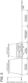
FIG. 5 is a diagram showing another example of the timing of supplying each of first fuel and second fuel to main combustion chamber within one combustion cycle of gas engine. -
FIG. 6 is a diagram showing another example of the timing of supplying each of first fuel and second fuel to main combustion chamber within one combustion cycle of gas engine. -
FIG. 7 is a diagram showing another example of the timing of supplying each of first fuel and second fuel to main combustion chamber within one combustion cycle of gas engine. -
FIG. 8 is a diagram showing another example of the timing of supplying each of first fuel and second fuel to main combustion chamber within one combustion cycle of gas engine. -
FIG. 9 is a diagram showing another example of the timing of supplying each of first fuel and second fuel to main combustion chamber within one combustion cycle of gas engine. -
FIG. 10 is a diagram showing another example of a configuration for supplying fuel gas to intake line. - Embodiments of the present disclosure will be described below with reference to the accompanying drawings. It is intended, however, that unless particularly identified, dimensions, materials, shapes, relative positions and the like of components described or shown in the drawings as the embodiments shall be interpreted as illustrative only and not intended to limit the scope of the present invention.
- For instance, an expression of relative or absolute arrangement such as "in a direction", "along a direction", "parallel", "orthogonal", "centered", "concentric" and "coaxial" shall not be construed as indicating only the arrangement in a strict literal sense, but also includes a state where the arrangement is relatively displaced by a tolerance, or by an angle or a distance whereby it is possible to achieve the same function.
- For instance, an expression of an equal state such as "same" "equal" and "uniform" shall not be construed as indicating only the state in which the feature is strictly equal, but also includes a state in which there is a tolerance or a difference that can still achieve the same function.
- Further, for instance, an expression of a shape such as a rectangular shape or a cylindrical shape shall not be construed as only the geometrically strict shape, but also includes a shape with unevenness or chamfered corners within the range in which the same effect can be achieved.
- On the other hand, an expression such as "comprise", "include", "have", "contain" and "constitute" are not intended to be exclusive of other components.
-
FIG. 1 is a schematic configuration diagram of agas engine 2 according to some embodiments of the present disclosure. - As shown in
FIG. 1 , thegas engine 2 is provided with an engine body 4, anintake line 6, anexhaust line 8, aturbocharger 10, and anair cooler 12. - In the example shown in
FIG. 1 , thegas engine 2 is a precombustion chamber gas engine, and the engine body 4 includes a main combustion chamber 18 (main chamber) defined between apiston 14 and acylinder head 16, and a precombustion chamber 26 (auxiliary chamber) communicating with themain combustion chamber 18. Theprecombustion chamber 26 is a space formed inside a precombustion-chamber forming part 28 and aprecombustion chamber cap 31 formed in thecylinder head 16 and communicates with themain combustion chamber 18 via a plurality ofnozzle holes 30 formed in theprecombustion chamber cap 31. - The
intake line 6 is connected to themain combustion chamber 18 and is configured to supply a mixture (lean premixture) of at least one type of fuel gas and air to themain combustion chamber 18. Theintake line 6 includes anintake port 32 formed in thecylinder head 16 and anintake pipe 34 connected to theintake port 32. One end of theintake port 32 is connected to themain combustion chamber 18, and the other end of theintake port 32 is connected to theintake pipe 34. Theintake port 32 is equipped with anintake valve 36 for controlling the connection between themain combustion chamber 18 and theintake pipe 34. - The supply of fuel gas (hereinafter, referred to as precombustion chamber fuel) to the
precombustion chamber 26 is directly performed through a precombustionchamber fuel line 29 connected to theprecombustion chamber 26. Then, a combustion flame is generated by ignition of the fuel (precombustion chamber fuel and lean premixture flowing from main combustion chamber 18) in theprecombustion chamber 26 with an ignition device (in this embodiment, ignition plug 37) disposed in the precombustion-chamber forming part 28. This combustion flame is injected from theprecombustion chamber 26 to themain combustion chamber 18 via the plurality ofnozzle holes 30, so that the fuel (lean premixture) in themain combustion chamber 18 is combusted. - The
exhaust line 8 is connected to themain combustion chamber 18 and is configured to discharge combustion gas generated by combustion of the fuel in themain combustion chamber 18 as exhaust gas from themain combustion chamber 18. Theexhaust line 8 includes anexhaust port 38 formed in thecylinder head 16 and anexhaust pipe 40 connected to theexhaust port 38. One end of theexhaust port 38 is connected to themain combustion chamber 18, and the other end of theexhaust port 38 is connected to theexhaust pipe 40. Theexhaust port 38 is equipped with anexhaust valve 42 for controlling the connection between themain combustion chamber 18 and theexhaust pipe 40. Theintake valve 36 and theexhaust valve 42 open and close theintake port 32 and theexhaust port 38, respectively, depending on the crank angle of the crankshaft (not shown). - The
turbocharger 10 includes acompressor 44 disposed in theintake line 6, aturbine 46 disposed in theexhaust line 8, and arotational shaft 48 connecting thecompressor 44 and theturbine 46. When theturbine 46 is driven by exhaust gas flowing through theexhaust line 8, the rotation of theturbine 46 is transmitted to thecompressor 44 via therotational shaft 48, and thecompressor 44 compresses air flowing through theintake line 6. - The
air cooler 12 is disposed between thecompressor 44 and the engine body 4 (betweencompressor 44 and intake port 32) in theintake line 6 and is configured to cool air that is heated by compression in thecompressor 44. - The above-described
gas engine 2 is configured to supply two or more types of fuel gas (two types in the illustrated example) to theintake line 6, as shown inFIG. 2 , for example. - As shown in
FIG. 2 , thegas engine 2 is provided with afirst fuel line 50 configured to supply the first fuel to theintake line 6, asecond fuel line 52 configured to supply the second fuel having a lower explosive limit that is higher than that of the first fuel to theintake line 6, a firstflow regulating valve 54 disposed in thefirst fuel line 50, a secondflow regulating valve 56 disposed in thesecond fuel line 52, and acontrol device 58 configured to control the firstflow regulating valve 54 and the secondflow regulating valve 56. - In the example shown in
FIG. 2 , thefirst fuel line 50 and thesecond fuel line 52 join and then connect to theintake line 6. Specifically, thefirst fuel line 50 is connected (merged) to thesecond fuel line 52 at position P downstream of the firstflow regulating valve 54 and downstream of the secondflow regulating valve 56, and thefirst fuel line 50 and thesecond fuel line 52 share acommon line part 55 which connects the position P and theintake line 6. - The first fuel is a main gaseous component of fuel gas supplied from the
first fuel line 50 to theintake line 6 and may be, for example, any of hydrogen, methane, propane, n-butane, carbon monoxide, and ammonia. The second fuel is a main gaseous component of fuel gas supplied from the second fuel line to theintake line 6 and may be, for example, any of hydrogen, methane, propane, n-butane, carbon monoxide, and ammonia with a lower explosive limit that is higher than that of the first fuel. For example, the first fuel may be hydrogen, and the second fuel may be methane. Alternatively, for example, the first fuel may be methane, and the second fuel may be ammonia. The lower explosive limits of hydrogen, methane, propane, n-butane, carbon monoxide, and ammonia are 4.0%, 5.0%, 2.1%, 1.8%, 12.5%, and 15.0%, respectively. The concentration of the first fuel in the gas flowing through the first fuel line and the concentration of the second fuel in the gas flowing through the second fuel line may be, for example, not less than 50% or not less than 80% each. -
FIG. 3 is a diagram showing an example of a hardware configuration of thecontrol device 58. - As shown in
FIG. 3 , thecontrol device 58 may be provided by a computer including aprocessor 72, a random access memory (RAM) 74, a read only memory (ROM) 76, a hard disk drive (HDD) 78, an input I/F 80, and an output I/F 82, which are connected via abus 84, for example. The hardware configuration of thecontrol device 58 is not limited to the above, and may be configured by a combination of a control circuit and a storage device. Thecontrol device 58 is provided by executing a program that realizes each function of thecontrol device 58 by the computer. The function of each unit of thecontrol device 58 described below is realized by, for instance, loading a program stored in theROM 76 into theRAM 74 and executing the program by theprocessor 72, and reading and writing data in theRAM 74 or theROM 76. -
FIGs. 4 to 10 are diagrams showing examples of the timing of opening/closing of each of theintake valve 36 and theexhaust valve 42 and the timing of supplying each of the first fuel and the second fuel to themain combustion chamber 18 within one combustion cycle of thegas engine 2. In each ofFIGs. 4 to 10 , the horizontal axis represents the crank angle (or time) and the vertical axis represents the fuel flow rate or the effective opening area of each of theintake valve 36 and theexhaust valve 42. - In some embodiments, for example, as shown in
FIGs. 4 to 10 , thecontrol device 58 controls the firstflow regulating valve 54 and the secondflow regulating valve 56 so that the first fuel is supplied to themain combustion chamber 18 before the second fuel is supplied to themain combustion chamber 18 in the intake process of thegas engine 2. - In conventional gas engines, when fuel gas is supplied from the intake line to the main combustion chamber during the intake process, the fuel gas supplied to the intake line in the latter half of the intake process tends to remain in the intake line after the intake valve is closed. Therefore, at the timing when the intake valve opens in the next intake process (e.g., timing A in
FIG. 4 ), the gas in the main combustion chamber may flow slightly backward into the intake line, which may ignite the fuel gas remaining in the intake line and cause backfires. - In contrast, in some embodiments shown in
FIGs. 4 to 10 , as described above, the first fuel, which has a relatively low lower explosive limit among the first and second fuels, is supplied to themain combustion chamber 18 before the second fuel in the intake process of thegas engine 2. This reduces the amount of the first fuel, which has a relatively low lower explosive limit and is likely to cause backfires, remaining in theintake line 6 when the intake process is completed (when theintake valve 36 is closed in the intake process), compared to the case where the first fuel is supplied to themain combustion chamber 18 after the second fuel. Thus, it is possible to reduce the risk of backfires and suppress damage to thegas engine 2 caused by backfires. - For example, when the first fuel is hydrogen and the second fuel is methane, the use of hydrogen reduces carbon dioxide emissions compared to using only methane as fuel. Hydrogen has a lower lower explosive limit and a higher combustion rate than methane, but supplying hydrogen before methane reduces the amount of hydrogen remaining in the
intake line 6 after theintake valve 36 is closed, suppressing damage to thegas engine 2 caused by hydrogen-induced backfires. - Alternatively, when the first fuel is methane and the second fuel is ammonia, the use of ammonia reduces carbon dioxide emissions compared to using only methane as fuel. Further, since methane has a lower lower explosive limit and a higher combustion rate than ammonia, supplying methane before ammonia reduces the amount of methane remaining in the
intake line 6 after theintake valve 36 is closed, suppressing damage to thegas engine 2 caused by methane-induced backfires. - In an embodiment, for example, as shown in
FIG. 4 , thecontrol device 58 may control the firstflow regulating valve 54 and the secondflow regulating valve 56 so that the first fuel is supplied to themain combustion chamber 18 during the first period T1 in the intake process and the second fuel is supplied to themain combustion chamber 18 during the second period T2 that is consecutive to the first period T1 in the intake process. In the example shown inFIG. 4 , the first fuel is supplied to themain combustion chamber 18 at a constant flow rate during the first period T1 in an earlier part of the intake process, and the second fuel is supplied to themain combustion chamber 18 at a constant flow rate during the second period T2 in a later part of the intake process. - In an embodiment, for example, as shown in
FIG. 5 , thecontrol device 58 may control the firstflow regulating valve 54 and the secondflow regulating valve 56 so that the first fuel is supplied to themain combustion chamber 18 during the first period T1 in the intake process and the second fuel is supplied to themain combustion chamber 18 during the second period T2 after a certain time interval from the first period T1 in the intake process. In the example shown inFIG. 5 , the first fuel is supplied to themain combustion chamber 18 at a constant flow rate during the first period T1 in an earlier part of the intake process, the first and second fuels are not supplied to themain combustion chamber 18 during the period between the first period T1 and the second period T2, and the second fuel is supplied at a constant flow rate to themain combustion chamber 18 during the second period T2 in a later part of the intake process. - According to the control shown in
FIG. 5 , the time difference between the end of period T1, in which the first fuel with a relatively low lower explosive limit among the first and second fuels (i.e., fuel that is likely to cause backfires) is supplied, and the end of period T2, in which the second fuel with a relatively high lower explosive limit (i.e., fuel that is unlikely to cause backfires) is supplied, can be large. This increases the effect of reducing the risk of backfires and effectively suppresses damage to thegas engine 2 caused by backfires. - In an embodiment, for example, as shown in
FIG. 6 , thecontrol device 58 may control the firstflow regulating valve 54 and the secondflow regulating valve 56 so that the second period T2, in which the second fuel is supplied to themain combustion chamber 18, is longer than the first period T1, in which the first fuel is supplied to themain combustion chamber 18 in the intake process. In the example shown inFIG. 6 , the first fuel is supplied to themain combustion chamber 18 at a constant flow rate F1 during the first period T1 in an earlier part of the intake process, and the second fuel is supplied to themain combustion chamber 18 at a constant flow rate F2 smaller than the flow rate F1 during the second period T2 that is consecutive to the first period T1. - According to the control shown in
FIG. 6 , the time difference between the end of period T1, in which the first fuel with a relatively low lower explosive limit among the first and second fuels (i.e., fuel that is likely to cause backfires) is supplied, and the end of period T2, in which the second fuel with a relatively high lower explosive limit (i.e., fuel that is unlikely to cause backfires) is supplied, can be large. This increases the effect of reducing the risk of backfires and effectively suppresses damage to thegas engine 2 caused by backfires. - In some embodiments, for example, as shown in
FIGs. 7 to 9 , thecontrol device 58 may control the firstflow regulating valve 54 and the secondflow regulating valve 56 so that the flow rate of the first fuel to themain combustion chamber 18 is decreased with time while the flow rate of the second fuel to themain combustion chamber 18 is increased with time in the intake process. - In this case, for example, as shown in
FIG. 7 , from time t0 to time t1 in the intake process, the flow rate of the first fuel to themain combustion chamber 18 may be gradually (linearly in the illustrated example) decreased and the flow rate of the second fuel to themain combustion chamber 18 may be gradually (linearly in the illustrated example) increased. - In the example shown in
FIG. 8 , the first fuel is supplied to themain combustion chamber 18 at a constant flow rate during the period from time ta to tb in the intake process, the flow rate of the first fuel to themain combustion chamber 18 is then gradually (linearly in the illustrated example) decreased during the period from time tb to tc, and the flow rate of the first fuel to themain combustion chamber 18 is set to zero during the period from time tc to time td. Further, the flow rate of the second fuel to themain combustion chamber 18 is set to 0 during the period from time ta to tb in the intake process, the flow rate of the second fuel to themain combustion chamber 18 is then gradually (linearly in the illustrated example) increased during the period from time tb to tc, and the second fuel is supplied to themain combustion chamber 18 at a constant flow rate during the period from time tc to time td. - In the example shown in
FIG. 9 , from time ta to time td in the intake process, the flow rate of the first fuel to themain combustion chamber 18 is stepwise decreased with time and the flow rate of the second fuel to themain combustion chamber 18 is stepwise increased with time. In the example shown inFIG. 9 , the first fuel is supplied to themain combustion chamber 18 at a constant flow rate F1 during the period from time ta to tb, the first fuel is then supplied to themain combustion chamber 18 at a constant flow rate F2 smaller than the flow rate F1 during the period from time tb to tc, and the flow rate of the first fuel to themain combustion chamber 18 is set to zero during the period from time tc to time td. Further, the flow rate of the second fuel to themain combustion chamber 18 is set to 0 during the period from time ta to tb, the first fuel is supplied to themain combustion chamber 18 at a constant flow rate F3 during the period from time tb to tc, and the first fuel is supplied to themain combustion chamber 18 at a constant flow rate F4 larger than the flow rate F3 during the period from time tc to time td. - According to the control shown in each of
FIGs. 7 to 9 , the risk of backfires can be reduced while reducing the risk of combustion deterioration due to poor mixing of the two types of fuel gas (first fuel and second fuel) in themain combustion chamber 18. - The present disclosure is not limited to the embodiments described above, but includes modifications to the embodiments described above, and embodiments composed of combinations of those embodiments.
- For example, in the example shown in
FIG. 2 , thefirst fuel line 50 and thesecond fuel line 52 join and then connect to theintake line 6, but as shown inFIG. 10 , for example, thefirst fuel line 50 may be connected to theintake line 6 at the first position P1, and thesecond fuel line 52 may be connected to theintake line 6 at the position P2 upstream of the first position P1. - Also in this case, the control of the first
flow regulating valve 54 and the secondflow regulating valve 56 described usingFIGs. 4 to 9 (control of supplying the first fuel to themain combustion chamber 18 before supplying the second fuel to themain combustion chamber 18 in the intake process) can be performed in the same manner by thecontrol device 58 to reduce the risk of backfires and suppress engine damage caused by backfires. Further, since the first fuel, which has a lower explosive limit that is lower than the second fuel, is more likely to cause backfires than the second fuel, by setting the first position P1 where the first fuel line is connected to theintake line 6 downstream from the position P2 where the second fuel line is connected to theintake line 6 as described above, in the event of a backfire, the area affected by the backfire in theintake line 6 can be reduced, and damage to thegas engine 2 caused by the backfire can be suppressed. - The gas engine may supply three or more types of fuel gas to the
intake line 6. In this case, three or more types of fuel may be supplied to themain combustion chamber 18, starting with the fuel with the lowest lower explosive limit. Thus, it is possible to reduce the risk of backfires and suppress damage to thegas engine 2 caused by backfires. - The gas engine does not have to be a precombustion chamber gas engine, and the gas engine does not have to have a precombustion chamber.
- The present disclosure is not limited to gas engines, but can also be applied to diesel engines, for example. The "lower explosive limit" described above may be read as "lower limit of combustible range" or "lower limit of combustion range". Also, "low lower explosive limit" can be read as "high explosive grade". The higher explosive grade takes precedence over the lower lower explosive limit. If the explosive grade is the same, the judgment is made by the lower explosive limit.
- In the example shown in
FIG. 10 , thesecond fuel line 52 is connected to theintake line 6 at a position upstream of where thefirst fuel line 50 is connected, but thesecond fuel line 52 may be connected to theintake line 6 at the same position in the intake air flow direction as where thefirst fuel line 50 is connected. In this case, thefirst fuel line 50 and thesecond fuel line 52 may be connected to different circumferential positions of the pipe constituting theintake line 6. - The contents described in the above embodiments would be understood as follows, for instance.
- (1) An engine (e.g., the above-described gas engine 2) according to at least one embodiment of the present disclosure is provided with: an engine body (e.g., the above-described engine body 4); an intake line (e.g., the above-described intake line 6) connected to a combustion chamber (e.g., the above-described main combustion chamber 18) of the engine body; a first fuel line (e.g., the above-described first fuel line 50) configured to supply a first fuel (e.g., any of the above-described hydrogen, methane, propane, n-butane, carbon monoxide, and ammonia) to the intake line; a second fuel line (e.g., the above-described second fuel line 52) configured to supply a second fuel having a lower explosive limit that is higher than that of the first fuel (e.g., any of the above-described hydrogen, methane, propane, n-butane, carbon monoxide, and ammonia having a lower explosive limit that is higher than that of the first fuel) to the intake line; a first flow regulating valve (e.g., the above-described first flow regulating valve 54) disposed in the first fuel line; a second flow regulating valve (e.g., the above-described second flow regulating valve 56) disposed in the second fuel line; and a control device (e.g., the above-described control device 58) configured to control the first flow regulating valve and the second flow regulating valve so that the first fuel is supplied to the combustion chamber before the second fuel is supplied to the combustion chamber in an intake process.
- Conventionally, when fuel gas is supplied from the intake line to the main combustion chamber during the intake process, the fuel gas supplied to the intake line in the latter half of the intake process tends to remain in the intake line after the intake valve is closed. Therefore, at the timing when the intake valve opens in the next intake process, the gas in the combustion chamber may flow slightly backward into the intake line, which may ignite the fuel gas remaining in the intake line and cause backfires.
- In contrast, in the engine described in (1), the control device controls the first flow regulating valve and the second flow regulating valve so that the first fuel is supplied to the combustion chamber before the second fuel is supplied to the combustion chamber in the intake process. Thus, the first fuel, which has a relatively low lower explosive limit among the first and second fuels, is supplied to the combustion chamber before the second fuel in the intake process to reduce the amount of the first fuel, which has a relatively low lower explosive limit and is likely to cause backfires, remaining in the intake line when the intake process is completed (when the intake valve is closed in the intake process), compared to the case where the first fuel is supplied to the combustion chamber after the second fuel. Thus, it is possible to reduce the risk of backfires and suppress damage to the engine caused by backfires.
- (2) In some embodiments, in the engine described in the above (1), when a period (e.g., the above-described period T1) during which the first fuel is supplied to the combustion chamber in the intake process is a first period, the control device is configured to control the first flow regulating valve and the second flow regulating valve so that the second fuel is supplied to the combustion chamber during a second period (e.g., the above-described period T2) that is consecutive to the first period in the intake process.
- With the engine described in (2), it is possible to reduce the risk of backfires and suppress damage to the
gas engine 2 caused by backfires. - (3) In some embodiments, in the engine described in the above (1), when a period (e.g., the above-described period T1) during which the first fuel is supplied to the combustion chamber in the intake process is a first period, the control device is configured to control the first flow regulating valve and the second flow regulating valve so that the second fuel is supplied to the combustion chamber during a second period (e.g., the above-described period T2) after a certain time interval from the first period in the intake process.
- With the engine described in (3), the time difference between the end of first period, in which the first fuel with a relatively low lower explosive limit among the first and second fuels (i.e., fuel that is likely to cause backfires) is supplied, and the end of second period, in which the second fuel with a relatively high lower explosive limit (i.e., fuel that is unlikely to cause backfires) is supplied, can be large. This increases the effect of reducing the risk of backfires and effectively suppresses damage to the engine caused by backfires.
- (4) In some embodiments, in the engine described in any one of the above (1) to (3), when a period (e.g., the above-described period T1) during which the first fuel is supplied to the combustion chamber in the intake process is a first period, and a period (e.g., the above-described period T2) during which the second fuel is supplied to the combustion chamber in the intake process is a second period, the control device is configured to control the first flow regulating valve and the second flow regulating valve so that the second period is longer than the first period.
- With the engine described in (4), the time difference between the end of first period, in which the first fuel with a relatively low lower explosive limit among the first and second fuels (i.e., fuel that is likely to cause backfires) is supplied, and the end of second period, in which the second fuel with a relatively high lower explosive limit (i.e., fuel that is unlikely to cause backfires) is supplied, can be large. This increases the effect of reducing the risk of backfires and effectively suppresses damage to the engine caused by backfires.
- (5) In some embodiments, in the engine described in the above (1), the control device is configured to control the first flow regulating valve and the second flow regulating valve so that flow rate of the first fuel to the combustion chamber is decreased with time while flow rate of the second fuel to the combustion chamber is increased with time in the intake process.
- With the engine described in (5), the risk of backfires can be reduced while reducing the risk of combustion deterioration due to poor mixing of the first fuel and the second fuel in the combustion chamber.
- (6) In some embodiments, in the engine described in any one of the above (1) to (5), the first fuel line is connected to the intake line at a first position (e.g., the above-described position P1). The second fuel line is connected to the intake line at a position (e.g., the above-described position P2) upstream of the first position.
- With the engine described in (5), the first fuel line and the second fuel line are independent, which facilitates control of the fuel supply amount for each fuel line.
- (7) In some embodiments, in the engine described in any one of the above (1) to (5), the first fuel line and the second fuel line join and then connect to the intake line.
- With the engine described in (6), the fuel line can be connected to the intake line at a single position.
- (8) In some embodiments, in the engine described in any one of the above (1) to (7), the first fuel is hydrogen, and the second fuel is methane.
- With the engine described in (8), carbon dioxide emissions can be reduced by using hydrogen compared to conventional engines that use only methane as fuel. Hydrogen has a lower lower explosive limit and a higher combustion rate than methane, but supplying hydrogen before methane reduces the amount of hydrogen remaining in the intake line after the intake valve is closed, suppressing damage to the engine caused by hydrogen-induced backfires.
- (9) In some embodiments, in the engine described in any one of the above (1) to (7), the first fuel is methane or hydrogen, and the second fuel is ammonia.
- With the engine described in (9), carbon dioxide emissions can be reduced by using ammonia compared to conventional engines that use only methane as fuel. Further, since methane has a lower lower explosive limit and a higher combustion rate than ammonia, supplying methane or hydrogen before ammonia reduces the amount of methane remaining in the intake line after the intake valve is closed, suppressing damage to the engine caused by methane-induced backfires.
- (10) A control method according to at least one embodiment of the present disclosure for controlling an engine that is provided with: an engine body; an intake line connected to a combustion chamber of the engine body; a first fuel line configured to supply a first fuel to the intake line; and a second fuel line configured to supply a second fuel having a lower explosive limit that is higher than that of the first fuel to the intake line includes a step of supplying the first fuel from the first fuel line to the combustion chamber before the second fuel is supplied from the second fuel line to the combustion chamber in an intake process.
- Conventionally, when fuel gas is supplied from the intake line to the main combustion chamber during the intake process, the fuel gas supplied to the intake line in the latter half of the intake process tends to remain in the intake line after the intake valve is closed. Therefore, at the timing when the intake valve opens in the next intake process, the gas in the combustion chamber may flow slightly backward into the intake line, which may ignite the fuel gas remaining in the intake line and cause backfires.
- In contrast, in the engine control method described in (10) includes the step of supplying the first fuel to the combustion chamber before the second fuel is supplied to the combustion chamber in the intake process. Thus, the first fuel, which has a relatively low lower explosive limit among the first and second fuels, is supplied to the combustion chamber before the second fuel in the intake process. This reduces the amount of the first fuel, which has a relatively low lower explosive limit and is likely to cause backfires, remaining in the intake line when the intake process is completed (when the intake valve is closed in the intake process), compared to the case where the first fuel is supplied to the combustion chamber after the second fuel. Thus, it is possible to reduce the risk of backfires and suppress damage to the engine caused by backfires.
-
- 2
- Gas engine
- 4
- Engine body
- 6
- Intake line
- 8
- Exhaust line
- 10
- Supercharger
- 12
- Air cooler
- 14
- Piston
- 16
- Cylinder head
- 18
- Main combustion chamber
- 26
- Precombustion chamber
- 28
- Precombustion-chamber forming part
- 29
- Precombustion chamber fuel line
- 30
- Nozzle hole
- 31
- Precombustion chamber cap
- 32
- Intake port
- 34
- Intake pipe
- 36
- Intake valve
- 37
- Ignition plug
- 38
- Exhaust port
- 40
- Exhaust pipe
- 42
- Exhaust valve
- 44
- Compressor
- 46
- Turbine
- 48
- Rotational shaft
- 50
- First fuel line
- 52
- Second fuel line
- 54
- First flow regulating valve
- 55
- Common line part
- 56
- Second flow regulating valve
- 58
- Control device
- 72
- Processor
- 74
- RAM
- 76
- ROM
- 78
- HDD
- 80
- Input I/F
- 82
- Output I/F
- 84
- Bus
Claims (10)
- An engine, comprising:an engine body;an intake line connected to a combustion chamber of the engine body;a first fuel line configured to supply a first fuel to the intake line;a second fuel line configured to supply a second fuel having a lower explosive limit that is higher than that of the first fuel to the intake line;a first flow regulating valve disposed in the first fuel line;a second flow regulating valve disposed in the second fuel line; anda control device configured to control the first flow regulating valve and the second flow regulating valve so that the first fuel is supplied to the combustion chamber before the second fuel is supplied to the combustion chamber in an intake process.
- The engine according to claim 1,
wherein when a period during which the first fuel is supplied to the combustion chamber in the intake process is a first period, the control device is configured to control the first flow regulating valve and the second flow regulating valve so that the second fuel is supplied to the combustion chamber during a second period that is consecutive to the first period in the intake process. - The engine according to claim 1,
wherein when a period during which the first fuel is supplied to the combustion chamber in the intake process is a first period, the control device is configured to control the first flow regulating valve and the second flow regulating valve so that the second fuel is supplied to the combustion chamber during a second period after a certain time interval from the first period in the intake process. - The engine according to any one of claims 1 to 3,
wherein when a period during which the first fuel is supplied to the combustion chamber in the intake process is a first period, and a period during which the second fuel is supplied to the combustion chamber in the intake process is a second period, the control device is configured to control the first flow regulating valve and the second flow regulating valve so that the second period is longer than the first period. - The engine according to claim 1,
wherein the control device is configured to control the first flow regulating valve and the second flow regulating valve so that flow rate of the first fuel to the combustion chamber is decreased with time while flow rate of the second fuel to the combustion chamber is increased with time in the intake process. - The engine according to any one of claims 1 to 5,wherein the first fuel line is connected to the intake line at a first position, andwherein the second fuel line is connected to the intake line at a position upstream of the first position.
- The engine according to any one of claims 1 to 5,
wherein the first fuel line and the second fuel line join and then connect to the intake line. - The engine according to any one of claims 1 to 7,wherein the first fuel is hydrogen, andwherein the second fuel is methane.
- The engine according to any one of claims 1 to 7,wherein the first fuel is methane or hydrogen, andwherein the second fuel is ammonia.
- A method of controlling an engine,
the engine comprising:an engine body;an intake line connected to a combustion chamber of the engine body;a first fuel line configured to supply a first fuel to the intake line; anda second fuel line configured to supply a second fuel having a lower explosive limit that is higher than that of the first fuel to the intake line;the method comprising:
a step of supplying the first fuel from the first fuel line to the combustion chamber before the second fuel is supplied from the second fuel line to the combustion chamber in an intake process.
Applications Claiming Priority (2)
| Application Number | Priority Date | Filing Date | Title |
|---|---|---|---|
| JP2022018638A JP7826038B2 (en) | 2022-02-09 | 2022-02-09 | Engine and engine control method |
| PCT/JP2023/003523 WO2023153323A1 (en) | 2022-02-09 | 2023-02-03 | Engine and engine control method |
Publications (3)
| Publication Number | Publication Date |
|---|---|
| EP4455474A1 true EP4455474A1 (en) | 2024-10-30 |
| EP4455474A4 EP4455474A4 (en) | 2025-04-02 |
| EP4455474B1 EP4455474B1 (en) | 2026-03-18 |
Family
ID=87564266
Family Applications (1)
| Application Number | Title | Priority Date | Filing Date |
|---|---|---|---|
| EP23752788.2A Active EP4455474B1 (en) | 2022-02-09 | 2023-02-03 | Engine and engine control method |
Country Status (5)
| Country | Link |
|---|---|
| US (1) | US12372038B2 (en) |
| EP (1) | EP4455474B1 (en) |
| JP (1) | JP7826038B2 (en) |
| CN (1) | CN118613642A (en) |
| WO (1) | WO2023153323A1 (en) |
Families Citing this family (1)
| Publication number | Priority date | Publication date | Assignee | Title |
|---|---|---|---|---|
| JP7654855B1 (en) | 2024-03-18 | 2025-04-01 | 株式会社大島造船所 | Fuel injection valve, engine fuel injection system including same, and fuel injection method |
Family Cites Families (33)
| Publication number | Priority date | Publication date | Assignee | Title |
|---|---|---|---|---|
| DE3907049A1 (en) | 1989-03-04 | 1990-09-13 | Bayerische Motoren Werke Ag | VEHICLE WITH A SECURITY SYSTEM |
| DE19905721A1 (en) | 1998-02-24 | 1999-08-26 | Hoerbiger Ventilwerke Gmbh | Electromagnetically actuated gas valve for use as a fuel injection valve in a gas engine |
| JP4788018B2 (en) | 2000-06-08 | 2011-10-05 | トヨタ自動車株式会社 | Fuel cell fuel supply system and moving body |
| JP2002004965A (en) | 2000-06-23 | 2002-01-09 | Honda Motor Co Ltd | Fuel injection device for internal combustion engine |
| JP3960035B2 (en) | 2000-12-28 | 2007-08-15 | 三菱マテリアル株式会社 | Hybrid power system |
| US7338650B2 (en) | 2001-10-01 | 2008-03-04 | Gama-Greenol Research & Development Ltd. | Method and device for providing at least one fuel, in particular, for motor vehicle engines |
| DE10211122A1 (en) | 2002-03-14 | 2003-09-25 | Bosch Gmbh Robert | Process and device to operate a combustion engine, especially in a motor vehicle using multiple fuels, leads at least two fuels simultaneously into the combustion chamber |
| DE10215906A1 (en) | 2002-04-11 | 2003-10-23 | Bayerische Motoren Werke Ag | Dosing valve monitoring involves taking at least one pressure measurement with supply valve(s) closed, drawing conclusion re supply valves and/or shut-off valve faulty operation, damage and/or leakage |
| JP3814247B2 (en) | 2002-12-13 | 2006-08-23 | 三菱重工業株式会社 | Premixed forced ignition gas engine |
| US7617842B2 (en) | 2003-07-29 | 2009-11-17 | SOCIéTé BIC | Valves for fuel cartridges |
| JP4023434B2 (en) | 2003-11-13 | 2007-12-19 | トヨタ自動車株式会社 | Internal combustion engine capable of premixed compression self-ignition operation using two types of fuel |
| JP2005155528A (en) | 2003-11-27 | 2005-06-16 | Toyota Motor Corp | Internal combustion engine and control method for internal combustion engine |
| JP2005240586A (en) | 2004-02-24 | 2005-09-08 | Nippon Steel Corp | Combined system of low-temperature plasma apparatus and gas engine, and energy generation method |
| KR101536331B1 (en) | 2005-07-18 | 2015-07-14 | 인텔리전트 에너지 리미티드 | Detachable fuel source |
| EP1979076B1 (en) | 2006-02-01 | 2018-04-11 | Intelligent Energy, Inc. | Multi-stage sulfur removal system and process for an auxiliary fuel system |
| JP4682871B2 (en) | 2006-02-24 | 2011-05-11 | トヨタ自動車株式会社 | Working gas circulation hydrogen engine |
| RU2414609C2 (en) | 2006-04-07 | 2011-03-20 | Дэвид А. БЛЭНК | Control of combustion process during initiation of homogeneous combustion with free radicals (ihcfr) or partial ihcfr in cyclic internal combustion engines |
| JP4853451B2 (en) * | 2007-10-16 | 2012-01-11 | トヨタ自動車株式会社 | Engine system |
| JP4951592B2 (en) | 2008-07-07 | 2012-06-13 | 本田技研工業株式会社 | Control device for internal combustion engine |
| DE102008034221A1 (en) | 2008-07-23 | 2010-01-28 | Bayerische Motoren Werke Aktiengesellschaft | Fuel supply device for use in motor vehicle, has reactor vessel provided for executing heat exchanger and separator functions for supplying hydrogen for consumer through dehydration of carrier medium e.g. liquid organic hydrogen carrier |
| JP4881927B2 (en) * | 2008-09-11 | 2012-02-22 | 日立オートモティブシステムズ株式会社 | Fuel injection control device for internal combustion engine |
| JP2012172606A (en) | 2011-02-22 | 2012-09-10 | Ito Racing Service Co Ltd | Mixed fuel generation method, mixed fuel generation device, and fuel supply device |
| US8484971B2 (en) | 2011-02-25 | 2013-07-16 | Bendix Commercial Vehicle Systems Llc | Method of operating a vehicle equipped with a pneumatic booster system |
| US8666634B2 (en) | 2011-02-25 | 2014-03-04 | Bendix Commercial Vehicle Systems Llc | Method of operating a vehicle equipped with a pneumatic booster system |
| US8468824B2 (en) | 2011-02-25 | 2013-06-25 | Bendix Commercial Vehicle Systems Llc | Method of operating a vehicle equipped with a pneumatic booster system |
| US11952935B2 (en) * | 2011-12-16 | 2024-04-09 | Transportation Ip Holdings, Llc | Systems and method for controlling auto-ignition |
| JP6119199B2 (en) | 2012-11-08 | 2017-04-26 | 株式会社デンソー | Gas engine fuel supply device |
| US9263755B2 (en) | 2013-03-15 | 2016-02-16 | Exxonmobil Research And Engineering Company | Integration of molten carbonate fuel cells in iron and steel processing |
| JP6471041B2 (en) | 2015-05-28 | 2019-02-13 | 日立オートモティブシステムズ株式会社 | Injection controller for spark ignition engine |
| JP6806483B2 (en) * | 2015-12-11 | 2021-01-06 | 現代自動車株式会社Hyundai Motor Company | Vehicle injector control system |
| US20220018321A1 (en) * | 2016-10-31 | 2022-01-20 | Cummins Inc. | In-cylinder air injection via dual-fuel injector |
| JP6970250B1 (en) | 2020-07-16 | 2021-11-24 | 博志 西村 | Incinerator |
| US11598276B1 (en) * | 2021-12-08 | 2023-03-07 | Transportation Ip Holdings, Llc | Methods and systems for multi-fuel engine |
-
2022
- 2022-02-09 JP JP2022018638A patent/JP7826038B2/en active Active
-
2023
- 2023-02-03 WO PCT/JP2023/003523 patent/WO2023153323A1/en not_active Ceased
- 2023-02-03 US US18/833,332 patent/US12372038B2/en active Active
- 2023-02-03 EP EP23752788.2A patent/EP4455474B1/en active Active
- 2023-02-03 CN CN202380018957.6A patent/CN118613642A/en active Pending
Also Published As
| Publication number | Publication date |
|---|---|
| US20250154910A1 (en) | 2025-05-15 |
| EP4455474B1 (en) | 2026-03-18 |
| US12372038B2 (en) | 2025-07-29 |
| EP4455474A4 (en) | 2025-04-02 |
| CN118613642A (en) | 2024-09-06 |
| JP7826038B2 (en) | 2026-03-09 |
| JP2023116072A (en) | 2023-08-22 |
| WO2023153323A1 (en) | 2023-08-17 |
Similar Documents
| Publication | Publication Date | Title |
|---|---|---|
| US7739026B2 (en) | Control apparatus for combustion engine of premixed compression self-ignition type | |
| US9145837B2 (en) | Engine utilizing a plurality of fuels, and a related method thereof | |
| US9334841B1 (en) | Differential fueling between donor and non-donor cylinders in engines | |
| US8977469B2 (en) | Multi-fuel control system and method | |
| US10359008B2 (en) | Differential fueling between donor and non-donor cylinders in engines | |
| US9243548B2 (en) | Turbocharged power unit and method of operating under high load conditions | |
| US20160169142A1 (en) | System and method for optimal fueling of an engine | |
| US10961943B1 (en) | Method and system for controlling combustion of natural gas engine | |
| CN102257261B (en) | Internal combustion heat engine, control system, method for dimensioning the engine, and automobile with said engine | |
| JP2008291726A (en) | 6 cycle engine | |
| CN105673281B (en) | In a kind of gas/liquid double fuel cylinder/cylinder outer pair of injection apparatus and control method | |
| JP2024543462A (en) | METHOD FOR OPERATING INTERNAL COMBUSTION ENGINE AND INTERNAL COMBUSTION ENGINE | |
| EP3256704B1 (en) | Reducing unburned hydrocarbon emissions in gaseous fuelled lean-burn engines | |
| EP4455474B1 (en) | Engine and engine control method | |
| US4088099A (en) | Mixture compressing, external auto-ignition four-stroke cycle internal combustion engine | |
| EP4455464A1 (en) | Engine | |
| WO2024178499A1 (en) | Internal combustion engine and method of operating thereof | |
| JP2007211608A (en) | Control device for hydrogen engine | |
| JP2008196387A (en) | In-cylinder injection internal combustion engine control device | |
| KR102694698B1 (en) | Multi-fuel engine system and method for controlling the same | |
| JP2005105944A (en) | Premixed compression ignition engine and method of controlling operation thereof | |
| JPH05321670A (en) | Auxiliary chamber type lean combustion gas engine | |
| KR20250140445A (en) | Ammonia mixed combustion engine | |
| KR20260022075A (en) | Method of fuel injection control for internal combustion engine using hydrogen fuel | |
| JP2008291725A (en) | 6 cycle engine |
Legal Events
| Date | Code | Title | Description |
|---|---|---|---|
| STAA | Information on the status of an ep patent application or granted ep patent |
Free format text: STATUS: THE INTERNATIONAL PUBLICATION HAS BEEN MADE |
|
| PUAI | Public reference made under article 153(3) epc to a published international application that has entered the european phase |
Free format text: ORIGINAL CODE: 0009012 |
|
| STAA | Information on the status of an ep patent application or granted ep patent |
Free format text: STATUS: REQUEST FOR EXAMINATION WAS MADE |
|
| 17P | Request for examination filed |
Effective date: 20240724 |
|
| AK | Designated contracting states |
Kind code of ref document: A1 Designated state(s): AL AT BE BG CH CY CZ DE DK EE ES FI FR GB GR HR HU IE IS IT LI LT LU LV MC ME MK MT NL NO PL PT RO RS SE SI SK SM TR |
|
| REG | Reference to a national code |
Ref legal event code: R079 Ref country code: DE Ref document number: 602023013829 Country of ref document: DE Free format text: PREVIOUS MAIN CLASS: F02M0021020000 Ipc: F02D0019060000 |
|
| A4 | Supplementary search report drawn up and despatched |
Effective date: 20250305 |
|
| RIC1 | Information provided on ipc code assigned before grant |
Ipc: F02M 21/02 20060101ALI20250227BHEP Ipc: F02D 41/34 20060101ALI20250227BHEP Ipc: F02D 19/08 20060101ALI20250227BHEP Ipc: F02D 19/02 20060101ALI20250227BHEP Ipc: F02D 41/00 20060101ALI20250227BHEP Ipc: F02D 19/06 20060101AFI20250227BHEP |
|
| DAV | Request for validation of the european patent (deleted) | ||
| DAX | Request for extension of the european patent (deleted) | ||
| GRAP | Despatch of communication of intention to grant a patent |
Free format text: ORIGINAL CODE: EPIDOSNIGR1 |
|
| STAA | Information on the status of an ep patent application or granted ep patent |
Free format text: STATUS: GRANT OF PATENT IS INTENDED |
|
| INTG | Intention to grant announced |
Effective date: 20251022 |
|
| GRAS | Grant fee paid |
Free format text: ORIGINAL CODE: EPIDOSNIGR3 |
|
| GRAA | (expected) grant |
Free format text: ORIGINAL CODE: 0009210 |
|
| STAA | Information on the status of an ep patent application or granted ep patent |
Free format text: STATUS: THE PATENT HAS BEEN GRANTED |
|
| AK | Designated contracting states |
Kind code of ref document: B1 Designated state(s): AL AT BE BG CH CY CZ DE DK EE ES FI FR GB GR HR HU IE IS IT LI LT LU LV MC ME MK MT NL NO PL PT RO RS SE SI SK SM TR |
|
| REG | Reference to a national code |
Ref country code: CH Ref legal event code: F10 Free format text: ST27 STATUS EVENT CODE: U-0-0-F10-F00 (AS PROVIDED BY THE NATIONAL OFFICE) Effective date: 20260318 Ref country code: GB Ref legal event code: FG4D |
|
| REG | Reference to a national code |
Ref country code: IE Ref legal event code: FG4D |
|
| REG | Reference to a national code |
Ref country code: DE Ref legal event code: R096 Ref document number: 602023013829 Country of ref document: DE |