EP4455451A1 - Method for manufacturing a blade for a gas turbine, blade for a gas turbine and gas turbine - Google Patents
Method for manufacturing a blade for a gas turbine, blade for a gas turbine and gas turbine Download PDFInfo
- Publication number
- EP4455451A1 EP4455451A1 EP23170273.9A EP23170273A EP4455451A1 EP 4455451 A1 EP4455451 A1 EP 4455451A1 EP 23170273 A EP23170273 A EP 23170273A EP 4455451 A1 EP4455451 A1 EP 4455451A1
- Authority
- EP
- European Patent Office
- Prior art keywords
- groove
- blade body
- cover
- blade
- support
- Prior art date
- Legal status (The legal status is an assumption and is not a legal conclusion. Google has not performed a legal analysis and makes no representation as to the accuracy of the status listed.)
- Pending
Links
- 238000000034 method Methods 0.000 title claims abstract description 47
- 238000004519 manufacturing process Methods 0.000 title claims abstract description 17
- 238000001816 cooling Methods 0.000 claims abstract description 33
- 238000005304 joining Methods 0.000 claims abstract description 19
- 239000012530 fluid Substances 0.000 claims description 17
- 125000006850 spacer group Chemical group 0.000 claims description 16
- 239000000463 material Substances 0.000 claims description 15
- 238000005266 casting Methods 0.000 claims description 11
- 239000011800 void material Substances 0.000 claims description 5
- 239000007789 gas Substances 0.000 description 25
- 239000012809 cooling fluid Substances 0.000 description 15
- PXHVJJICTQNCMI-UHFFFAOYSA-N Nickel Chemical compound [Ni] PXHVJJICTQNCMI-UHFFFAOYSA-N 0.000 description 10
- 238000003466 welding Methods 0.000 description 10
- 239000000446 fuel Substances 0.000 description 9
- 230000008901 benefit Effects 0.000 description 8
- 239000000956 alloy Substances 0.000 description 6
- 229910045601 alloy Inorganic materials 0.000 description 6
- 230000008878 coupling Effects 0.000 description 6
- 238000010168 coupling process Methods 0.000 description 6
- 238000005859 coupling reaction Methods 0.000 description 6
- 229910052759 nickel Inorganic materials 0.000 description 6
- 239000007921 spray Substances 0.000 description 6
- LFQSCWFLJHTTHZ-UHFFFAOYSA-N Ethanol Chemical compound CCO LFQSCWFLJHTTHZ-UHFFFAOYSA-N 0.000 description 4
- 239000011248 coating agent Substances 0.000 description 4
- 238000000576 coating method Methods 0.000 description 4
- 229910017052 cobalt Inorganic materials 0.000 description 4
- 239000010941 cobalt Substances 0.000 description 4
- GUTLYIVDDKVIGB-UHFFFAOYSA-N cobalt atom Chemical compound [Co] GUTLYIVDDKVIGB-UHFFFAOYSA-N 0.000 description 4
- 238000004891 communication Methods 0.000 description 4
- 238000000227 grinding Methods 0.000 description 4
- 239000007788 liquid Substances 0.000 description 4
- VNWKTOKETHGBQD-UHFFFAOYSA-N methane Chemical compound C VNWKTOKETHGBQD-UHFFFAOYSA-N 0.000 description 4
- 230000007704 transition Effects 0.000 description 4
- 241000218642 Abies Species 0.000 description 3
- 238000002485 combustion reaction Methods 0.000 description 3
- 238000009792 diffusion process Methods 0.000 description 3
- 239000002904 solvent Substances 0.000 description 3
- 229910003266 NiCo Inorganic materials 0.000 description 2
- QCWXUUIWCKQGHC-UHFFFAOYSA-N Zirconium Chemical compound [Zr] QCWXUUIWCKQGHC-UHFFFAOYSA-N 0.000 description 2
- 239000000654 additive Substances 0.000 description 2
- 230000000996 additive effect Effects 0.000 description 2
- 238000005219 brazing Methods 0.000 description 2
- 239000000919 ceramic Substances 0.000 description 2
- 239000003795 chemical substances by application Substances 0.000 description 2
- 239000000567 combustion gas Substances 0.000 description 2
- 239000013078 crystal Substances 0.000 description 2
- -1 diesel Substances 0.000 description 2
- 238000010894 electron beam technology Methods 0.000 description 2
- 238000005530 etching Methods 0.000 description 2
- 238000010438 heat treatment Methods 0.000 description 2
- 239000001257 hydrogen Substances 0.000 description 2
- 229910052739 hydrogen Inorganic materials 0.000 description 2
- 125000004435 hydrogen atom Chemical class [H]* 0.000 description 2
- 239000003350 kerosene Substances 0.000 description 2
- 239000003345 natural gas Substances 0.000 description 2
- 238000010926 purge Methods 0.000 description 2
- 230000035882 stress Effects 0.000 description 2
- 238000011144 upstream manufacturing Methods 0.000 description 2
- 229910052727 yttrium Inorganic materials 0.000 description 2
- VWQVUPCCIRVNHF-UHFFFAOYSA-N yttrium atom Chemical compound [Y] VWQVUPCCIRVNHF-UHFFFAOYSA-N 0.000 description 2
- 229910052726 zirconium Inorganic materials 0.000 description 2
- 229920002472 Starch Polymers 0.000 description 1
- 230000006978 adaptation Effects 0.000 description 1
- 230000000712 assembly Effects 0.000 description 1
- 238000000429 assembly Methods 0.000 description 1
- 239000011247 coating layer Substances 0.000 description 1
- 230000000295 complement effect Effects 0.000 description 1
- 230000003247 decreasing effect Effects 0.000 description 1
- 238000005553 drilling Methods 0.000 description 1
- 230000000694 effects Effects 0.000 description 1
- 238000000855 fermentation Methods 0.000 description 1
- 230000004151 fermentation Effects 0.000 description 1
- 239000000835 fiber Substances 0.000 description 1
- 238000002844 melting Methods 0.000 description 1
- 230000008018 melting Effects 0.000 description 1
- 239000007769 metal material Substances 0.000 description 1
- 238000003801 milling Methods 0.000 description 1
- 239000004033 plastic Substances 0.000 description 1
- 235000019698 starch Nutrition 0.000 description 1
- 239000008107 starch Substances 0.000 description 1
- 239000000126 substance Substances 0.000 description 1
- 230000003746 surface roughness Effects 0.000 description 1
- 238000004381 surface treatment Methods 0.000 description 1
- 230000008646 thermal stress Effects 0.000 description 1
- 239000012815 thermoplastic material Substances 0.000 description 1
Images


Classifications
-
- F—MECHANICAL ENGINEERING; LIGHTING; HEATING; WEAPONS; BLASTING
- F01—MACHINES OR ENGINES IN GENERAL; ENGINE PLANTS IN GENERAL; STEAM ENGINES
- F01D—NON-POSITIVE DISPLACEMENT MACHINES OR ENGINES, e.g. STEAM TURBINES
- F01D5/00—Blades; Blade-carrying members; Heating, heat-insulating, cooling or antivibration means on the blades or the members
- F01D5/12—Blades
- F01D5/14—Form or construction
- F01D5/18—Hollow blades, i.e. blades with cooling or heating channels or cavities; Heating, heat-insulating or cooling means on blades
- F01D5/187—Convection cooling
-
- F—MECHANICAL ENGINEERING; LIGHTING; HEATING; WEAPONS; BLASTING
- F01—MACHINES OR ENGINES IN GENERAL; ENGINE PLANTS IN GENERAL; STEAM ENGINES
- F01D—NON-POSITIVE DISPLACEMENT MACHINES OR ENGINES, e.g. STEAM TURBINES
- F01D25/00—Component parts, details, or accessories, not provided for in, or of interest apart from, other groups
- F01D25/08—Cooling; Heating; Heat-insulation
- F01D25/12—Cooling
-
- F—MECHANICAL ENGINEERING; LIGHTING; HEATING; WEAPONS; BLASTING
- F01—MACHINES OR ENGINES IN GENERAL; ENGINE PLANTS IN GENERAL; STEAM ENGINES
- F01D—NON-POSITIVE DISPLACEMENT MACHINES OR ENGINES, e.g. STEAM TURBINES
- F01D5/00—Blades; Blade-carrying members; Heating, heat-insulating, cooling or antivibration means on the blades or the members
- F01D5/12—Blades
- F01D5/14—Form or construction
- F01D5/147—Construction, i.e. structural features, e.g. of weight-saving hollow blades
-
- F—MECHANICAL ENGINEERING; LIGHTING; HEATING; WEAPONS; BLASTING
- F01—MACHINES OR ENGINES IN GENERAL; ENGINE PLANTS IN GENERAL; STEAM ENGINES
- F01D—NON-POSITIVE DISPLACEMENT MACHINES OR ENGINES, e.g. STEAM TURBINES
- F01D5/00—Blades; Blade-carrying members; Heating, heat-insulating, cooling or antivibration means on the blades or the members
- F01D5/12—Blades
- F01D5/28—Selecting particular materials; Particular measures relating thereto; Measures against erosion or corrosion
- F01D5/288—Protective coatings for blades
-
- F—MECHANICAL ENGINEERING; LIGHTING; HEATING; WEAPONS; BLASTING
- F05—INDEXING SCHEMES RELATING TO ENGINES OR PUMPS IN VARIOUS SUBCLASSES OF CLASSES F01-F04
- F05D—INDEXING SCHEME FOR ASPECTS RELATING TO NON-POSITIVE-DISPLACEMENT MACHINES OR ENGINES, GAS-TURBINES OR JET-PROPULSION PLANTS
- F05D2220/00—Application
- F05D2220/30—Application in turbines
- F05D2220/32—Application in turbines in gas turbines
-
- F—MECHANICAL ENGINEERING; LIGHTING; HEATING; WEAPONS; BLASTING
- F05—INDEXING SCHEMES RELATING TO ENGINES OR PUMPS IN VARIOUS SUBCLASSES OF CLASSES F01-F04
- F05D—INDEXING SCHEME FOR ASPECTS RELATING TO NON-POSITIVE-DISPLACEMENT MACHINES OR ENGINES, GAS-TURBINES OR JET-PROPULSION PLANTS
- F05D2230/00—Manufacture
- F05D2230/10—Manufacture by removing material
-
- F—MECHANICAL ENGINEERING; LIGHTING; HEATING; WEAPONS; BLASTING
- F05—INDEXING SCHEMES RELATING TO ENGINES OR PUMPS IN VARIOUS SUBCLASSES OF CLASSES F01-F04
- F05D—INDEXING SCHEME FOR ASPECTS RELATING TO NON-POSITIVE-DISPLACEMENT MACHINES OR ENGINES, GAS-TURBINES OR JET-PROPULSION PLANTS
- F05D2230/00—Manufacture
- F05D2230/10—Manufacture by removing material
- F05D2230/11—Manufacture by removing material by electrochemical methods
-
- F—MECHANICAL ENGINEERING; LIGHTING; HEATING; WEAPONS; BLASTING
- F05—INDEXING SCHEMES RELATING TO ENGINES OR PUMPS IN VARIOUS SUBCLASSES OF CLASSES F01-F04
- F05D—INDEXING SCHEME FOR ASPECTS RELATING TO NON-POSITIVE-DISPLACEMENT MACHINES OR ENGINES, GAS-TURBINES OR JET-PROPULSION PLANTS
- F05D2230/00—Manufacture
- F05D2230/10—Manufacture by removing material
- F05D2230/12—Manufacture by removing material by spark erosion methods
-
- F—MECHANICAL ENGINEERING; LIGHTING; HEATING; WEAPONS; BLASTING
- F05—INDEXING SCHEMES RELATING TO ENGINES OR PUMPS IN VARIOUS SUBCLASSES OF CLASSES F01-F04
- F05D—INDEXING SCHEME FOR ASPECTS RELATING TO NON-POSITIVE-DISPLACEMENT MACHINES OR ENGINES, GAS-TURBINES OR JET-PROPULSION PLANTS
- F05D2230/00—Manufacture
- F05D2230/10—Manufacture by removing material
- F05D2230/14—Micromachining
-
- F—MECHANICAL ENGINEERING; LIGHTING; HEATING; WEAPONS; BLASTING
- F05—INDEXING SCHEMES RELATING TO ENGINES OR PUMPS IN VARIOUS SUBCLASSES OF CLASSES F01-F04
- F05D—INDEXING SCHEME FOR ASPECTS RELATING TO NON-POSITIVE-DISPLACEMENT MACHINES OR ENGINES, GAS-TURBINES OR JET-PROPULSION PLANTS
- F05D2230/00—Manufacture
- F05D2230/20—Manufacture essentially without removing material
- F05D2230/21—Manufacture essentially without removing material by casting
-
- F—MECHANICAL ENGINEERING; LIGHTING; HEATING; WEAPONS; BLASTING
- F05—INDEXING SCHEMES RELATING TO ENGINES OR PUMPS IN VARIOUS SUBCLASSES OF CLASSES F01-F04
- F05D—INDEXING SCHEME FOR ASPECTS RELATING TO NON-POSITIVE-DISPLACEMENT MACHINES OR ENGINES, GAS-TURBINES OR JET-PROPULSION PLANTS
- F05D2240/00—Components
- F05D2240/20—Rotors
- F05D2240/30—Characteristics of rotor blades, i.e. of any element transforming dynamic fluid energy to or from rotational energy and being attached to a rotor
- F05D2240/304—Characteristics of rotor blades, i.e. of any element transforming dynamic fluid energy to or from rotational energy and being attached to a rotor related to the trailing edge of a rotor blade
-
- F—MECHANICAL ENGINEERING; LIGHTING; HEATING; WEAPONS; BLASTING
- F05—INDEXING SCHEMES RELATING TO ENGINES OR PUMPS IN VARIOUS SUBCLASSES OF CLASSES F01-F04
- F05D—INDEXING SCHEME FOR ASPECTS RELATING TO NON-POSITIVE-DISPLACEMENT MACHINES OR ENGINES, GAS-TURBINES OR JET-PROPULSION PLANTS
- F05D2240/00—Components
- F05D2240/20—Rotors
- F05D2240/30—Characteristics of rotor blades, i.e. of any element transforming dynamic fluid energy to or from rotational energy and being attached to a rotor
- F05D2240/305—Characteristics of rotor blades, i.e. of any element transforming dynamic fluid energy to or from rotational energy and being attached to a rotor related to the pressure side of a rotor blade
-
- F—MECHANICAL ENGINEERING; LIGHTING; HEATING; WEAPONS; BLASTING
- F05—INDEXING SCHEMES RELATING TO ENGINES OR PUMPS IN VARIOUS SUBCLASSES OF CLASSES F01-F04
- F05D—INDEXING SCHEME FOR ASPECTS RELATING TO NON-POSITIVE-DISPLACEMENT MACHINES OR ENGINES, GAS-TURBINES OR JET-PROPULSION PLANTS
- F05D2260/00—Function
- F05D2260/20—Heat transfer, e.g. cooling
- F05D2260/204—Heat transfer, e.g. cooling by the use of microcircuits
-
- F—MECHANICAL ENGINEERING; LIGHTING; HEATING; WEAPONS; BLASTING
- F05—INDEXING SCHEMES RELATING TO ENGINES OR PUMPS IN VARIOUS SUBCLASSES OF CLASSES F01-F04
- F05D—INDEXING SCHEME FOR ASPECTS RELATING TO NON-POSITIVE-DISPLACEMENT MACHINES OR ENGINES, GAS-TURBINES OR JET-PROPULSION PLANTS
- F05D2260/00—Function
- F05D2260/20—Heat transfer, e.g. cooling
- F05D2260/221—Improvement of heat transfer
- F05D2260/2214—Improvement of heat transfer by increasing the heat transfer surface
- F05D2260/22141—Improvement of heat transfer by increasing the heat transfer surface using fins or ribs
Definitions
- the present invention relates to a method for manufacturing a blade for a gas turbine, to a blade for a gas turbine, and to a gas turbine.
- Blades of gas turbines are subject to high thermal loads. Therefore, it is common to cool the blades by means of a cooling fluid, such as compressed air delivered by a compressor of the gas turbine.
- the cooling fluid typically, is conducted to an interior cavity of the blade and, from there, distributed to various cooling channels.
- the turbine blade includes an airfoil that is formed with an outer wall, wherein the outer wall includes an outer surface defining a suction side and a pressure side, and an inner surface that defines a cavity.
- a plurality of cooling channels is formed within the massive material between the inner and outer surface of the airfoil.
- the present invention provides a method for manufacturing a blade for a gas turbine in accordance with claim 1, a blade in accordance with claim 14, and a gas turbine in accordance with claim 15.
- a method for manufacturing a blade for a gas turbine includes forming a blade body, forming a groove in an outer surface of the blade body, positioning a cover on the blade body such that it covers the groove and such that an outer surface of the cover forms a continuous surface with the outer surface of the blade body, and joining the cover to the blade body so that the cover and the groove define a cooling channel.
- a blade for a gas turbine includes a blade body having an outer surface in which a groove is formed, and a cover positioned such that it covers the groove and such that an outer surface of the cover forms a continuous surface with the outer surface of the blade body, wherein the cover is joined to the blade body, and wherein the cover and the groove define a cooling channel.
- the blade according to this aspect of the invention may be manufactured using the method according to the first aspect of the invention.
- a gas turbine includes a blade according to the second aspect of the invention.
- the blade body with an open groove at its outer surface, first, and to subsequently join a cover to the blade body that covers the groove so that a cooling channel is limited by the walls of the groove and the cover.
- the groove may comprise a bottom and opposing sidewalls extending between the bottom of the groove and the outer surface of the blade body.
- the cover which may, for example, be generally strip shaped, is positioned on the blade body so that it covers the groove and so that its outer surface is flush or substantially flush with the outer surface of the blade body.
- the cover may be positioned, at least partially, within the groove, in particular, so that it protrudes into the groove, while its outer surface and the outer surface of the blade form a continuous surface.
- a “continuous surface” is not limited to a perfectly flush arrangement of the outer surface of the cover and the outer surface of the blade body but also includes configurations, in which the outer surface of the cover slightly protrudes over the outer surface of the blade body, e.g., by a height being smaller than 5 % of a wall thickness of the cover.
- the cooling channel limited by the walls or wall surfaces of the groove and an inner surface of the cover has a closed circumference, e.g., a rectangular or substantially rectangular circumference. Since the groove is formed as an open groove, tolerance based limits related to a minimum possible wall thickness are avoided.
- the thickness of the cover i.e. a distance between an inner surface and the outer surface of the cover, can be dimensioned according to the actual heat transfer needs, since the cover is manufactured as a separate component and joined subsequently to the blade body.
- heat transfer between a cooling fluid flowing in the cooling channel and an outer surface of the blade can be improved.
- thermal stress within the wall of the blade is reduced due to a lower temperature difference across the wall resulting from the lower wall thickness. Accordingly, lifetime of the blade is increased.
- a mass flow of the cooling fluid necessary to achieve a given heat transfer rate can be reduced. Thereby, the overall efficiency of the gas turbine is increased.
- the cover is a separate part that is subsequently joined to the blade body, the freedom in design to adjust cooling to the actual needs, e.g., to locally high heat loads, is increased. Further, replacing the cover, e.g., in a repairing process, is eased.
- blade is intended to cover both, a rotating blade, which may be coupled, for example, to a rotating disk of the gas turbine, and a stationary vane, which may be coupled, for example, to a stator frame of the gas turbine.
- the blade body may be formed to include an airfoil extending along a radial direction and a platform protruding along a circumferential direction from a platform end of the airfoil, wherein an outer surface of the airfoil and an outer surface of the platform form the outer surface of the blade body.
- the blade body may be formed to additionally include a root protruding from the platform in the radial direction on a side opposite to the airfoil.
- the root for example, may have a firtree shaped cross-section, and, generally, is configured to couple the blade to a rotor disk or to a frame, e.g. in case of a vane.
- the airfoil may be formed to extend in a chord or axial direction between a leading edge and a trailing edge, wherein a pressure side surface and a suction side surface of the airfoil meet at the leading and the trailing edge, and wherein the groove is formed in at least one of the pressure side surface and the suction side surface adjacent to the trailing edge. That is, a cooling channel formed beneath the outer surface of the airfoil is formed in a region very close to the trailing edge.
- Adjacent to the trailing edge may be understood as a distance, at each radial position of the airfoil, from the physical end of the airfoil formed by the trailing edge, the distance being in a range between 1 % and 20 % of a total length of the airfoil in the chord direction at the respective radial position.
- the total length of the airfoil in the chord direction in this context, may be defined as a length of a skeleton line connecting the leading and the trailing edge and being equally distanced to each of the pressure and the suction side surface.
- the cooling channel is formed by joining the cover to the airfoil having the groove, it is easier to place the cooling channel closer to the trailing edge, compared to forming the cooling channel exclusively in a casting process.
- airfoils with a small wedge angle at the trailing edge can easier be realized.
- the airfoil may be formed with a wedge angle at the trailing edge in a range between 7° and 17°.
- forming the blade body may include casting the blade body.
- a conventionally cast (CC), a directionally solidified (DS), or single crystal (SX) cast process may be carried out to form the blade body.
- the groove may be formed in the step of forming the blade body.
- the grooves may be formed during the casting process.
- the blade body may be formed to already include the grooves.
- the grooves may additionally be treated after forming the blade body, e.g. a surface treatment of the walls of the groove may be carried out, which may, for example, include at least one of grinding, die sinking, or similar.
- a surface treatment of the walls of the groove may be carried out, which may, for example, include at least one of grinding, die sinking, or similar.
- the groove may also be formed by applying an subtractive manufacturing process, such as grinding, die sinking, etching or similar, to the outer surface of the blade body after forming the blade body.
- an subtractive manufacturing process such as grinding, die sinking, etching or similar
- the blade body can be formed first, e.g., in a casting process, and the groove is formed subsequently by an subtractive method. This provides the benefit that the forming step of the blade body can be further eased. Additionally, subtractive processes can be carried out very precisely and with low manufacturing tolerances.
- the blade body may be formed to have an inner surface defining an inner cavity or void, wherein a wall thickness of the blade body is measured from the inner surface to the outer surface of the blade body.
- the inner cavity or void may, for example, extend within the airfoil and/or within a root of the blade body and is configured to receive a gaseous cooling fluid, such as compressed air.
- the wall thickness may be defined on each point of the inner and outer surface of the blade body as a shortest distance between the inner and the outer surface at the respective point.
- the wall thickness may be within a range between 1.5 and 4 times, optionally between 1.5 and 2 times, of a depth of the groove measured from the outer surface of the blade body to a bottom of the groove.
- a ratio W/h where "W” is the wall thickness and "h” is the depth of the groove, may be within a range of 1.5 to 4, in particular, between 1.5 and 2.
- the method may further include forming a fluid passage extending between the cavity and the groove.
- the inner cavity or void hence, may be formed to be in fluid communication with the groove.
- the blade body may be formed to include a communication channel extending between the groove and the cavity, or a communication hole may be drilled to extend from the groove to the cavity.
- multiple fluid passages e.g., in the form of holes, may be formed in this step.
- the method may include forming an outlet passage extending between the groove and the outer surface of the blade body. Through the outlet passage, the cooling fluid flowing in the cooling channel can be discharged to the outer surface of the blade body.
- the outlet passage may be drilled.
- the groove may be formed with a support defining a support surface being oriented such that a normal vector to the support surface has a component perpendicular to a region of the outer surface of the blade body adjacent to the groove.
- the groove may comprise a bottom and opposing sidewalls extending between the bottom of the groove and the outer surface of the blade body.
- the support may be integrally formed with at least one of the bottom and one or both of the sidewalls.
- the support generally, may be a physical structure or element that includes a surface that is oriented parallel or inclined to the portion of the outer surface that surrounds the groove or extends adjacent to the groove.
- a normal vector to the support surface has a component perpendicular to the region of the outer surface of the blade body adjacent to the groove. This allows placing the cover on the support surface, for example, before joining it to the blade body. Thereby, positioning and joining of the cover is eased.
- the support may be formed by a step in a sidewall of the groove, the support surface connecting two laterally spaced portions of the sidewall. That is, the sidewall may comprise a first portion extending from the bottom and a second portion extending from the outer surface of the blade body, wherein the second portion is spaced to the first portion in a direction perpendicular to the sidewalls, and wherein a step portion with the step surface extends between and connects the first and second portions of the sidewall. A distance between the first portion of the sidewall and the opposing sidewall is smaller than a distance between the second portion of the sidewall and the opposing sidewall. Hence, the second portion is laterally spaced to the first portion.
- the support surface may extend parallel to the region of the outer surface of the blade adjacent to the groove. The step provides the advantage that it reliably and stably supports the cover.
- the support may be formed by respective end portions of opposing sidewalls of the groove, wherein the support surface is formed by a surface of each sidewall, wherein the surfaces of the sidewalls, at least in the end portions, define a cross-section of the groove that tapers towards a bottom of the groove.
- the end portions of the sidewalls are opposite to the bottom.
- the end portions of the side walls are adjacent to or extend from the outer surface of the blade body.
- the surfaces of the sidewalls, in the end portions may, for example, extend tapering towards the bottom of the groove. This may include, for example, that the surfaces of the sidewalls, in the end portions, extend straight or planar, or that they extend with a concave curvature.
- a normal vector to the support surface which is formed by the surfaces of the sidewalls in their end portions, has a component perpendicular to the region of the outer surface of the blade body adjacent to the groove. This allows placing the cover on the support surface, for example, before joining it to the blade body. Thereby, positioning and joining of the cover is eased. Tapering end portions of the sidewall provides the advantage that they reliably and stably support the cover. Further, they help in centering the cover relative to the groove.
- the cover may include a spacer protruding from an inner surface of the cover, wherein positioning the cover on the blade body may include introducing the spacer into the groove so that the spacer contacts a bottom or a support surface of the groove to hold the outer surface of the cover in a position in which it forms a continuous surface with the outer surface of the blade body.
- the cover may include a protrusion, e.g. a rib, protruding from its inner surface that faces the bottom of the groove, when the cover is placed on the blade body.
- the spacer may be contacted to the bottom of the groove or to a support surface provided within one of the sidewalls, e.g., a support surface of a support as described above.
- the protrusion thus, serves as a spacer, that defines a distance between the bottom or the support surface and the outer surface of the cover, and that holds the cover in place, for example, during joining.
- the method may include introducing a spacing structure into the groove, wherein positioning the cover on the blade body includes positioning the cover on the spacing structure so that the spacing structure holds the cover in a position in which the outer surface of the cover forms a continuous surface with the outer surface of the blade body, and thermally or chemically removing the spacing structure after joining the cover to the blade body.
- the spacing structure may include stands, ribs, pins or other spacers, that are placed in the groove and dimensioned so that they hold the cover in a position in which the outer surface of the cover is substantially flush with the outer surface of the blade body.
- the spacing structure can be made, for example, from a plastic material, a material including natural fibers, a wax, or similar.
- the support structure After placing the cover on the support structure and joining the cover to the blade body, the support structure is removed thermally or chemically. This may include heating the blade body to a temperature above the melting temperature or combustion point of the support structure and purging the melted or burned structure out of the channel. Alternatively, removing the support structure may include introducing a solvent, e.g., in liquid form, into the channel, wherein the solvent dissolves or liquidates the support structure. The liquid support structure and the solvent are purged out of the channel finally. Using a support structure provides the advantage that the cross-sectional area of the channel can be maximized.
- a solvent e.g., in liquid form
- the cover may have a thickness in a range between 0.5 mm and 2.0 mm.
- the thickness may be measured between the inner and the outer surface of the cover.
- the range of 0.5 mm to 2.0 mm defines a relatively small wall thickness of the cover which allows for good heat transfer.
- the cover may have a thickness in a range between 0.8 mm and 1.2 mm. This range represents a good compromise between mechanical stiffness and heat transfer.
- joining the cover to the blade body may include positive substance joining, respective material bonding.
- joining may include brazing, diffusion bonding, or welding the cover and the blade body together.
- Welding for example, may include laser welding, arc welding, or electron beam welding.
- At least one of the groove and an inner surface of the cover is formed with at least one of projections and recesses. Those recesses and/or projections in the inner surface of the cover and/or the surface of the groove increase the effective area available for heat transfer. Hence, heat transfer can be further improved.
- the blade body may be made of a Nickel or Cobalt based high temperature alloy, such as, e.g., IN792SX, CM247LC, or similar.
- the cover may be made of a Nickel or Cobalt based high temperature alloy, in particular, an alloy suitable for additive manufacturing.
- a Nickel or Cobalt based high temperature alloy in particular, an alloy suitable for additive manufacturing.
- Hastelloy-X, Haynes 230, IN792SX, CM247LC, or similar may be used.
- the method may include applying a coating to the outer surface of the cover and the outer surface of the blade body.
- a MCrAlY material or other suitable material as bondcoat may be applied by a low pressure plasma spray (LPPS), an air plasma spray (APS), a vacuum plasma spray (VPS), or high velocity oxy fuel (HVOF) process.
- LPPS low pressure plasma spray
- APS air plasma spray
- VPS vacuum plasma spray
- HVOF high velocity oxy fuel
- the method may include applying a topcoat to the coating.
- a topcoat For example, a single or multi-layered ceramic, e.g., Yttrium stabilized zirconium (YSZ), may be applied by LPPS.
- YSZ Yttrium stabilized zirconium
- a further method for applying a topcoat would be, for example, APS.
- the gas turbine may comprise a compressor configured to compress a working fluid, a burner receiving compressed working fluid from the compressor and configured to burn a fuel to heat the working fluid, and a turbine including the turbine blade assembly, wherein the turbine stage is configured to expand the working fluid causing the turbine blade assembly to rotate.
- the blade assembly may form part of the turbine.
- the compressor may suck air from the environment, and the compressed air may be used for combustion of the fuel in the combustor or burner.
- liquid fuel such as kerosene, diesel, ethanol, or similar may be used.
- gaseous fuel such as natural gas, fermentation gas, hydrogen, or similar can be used.
- an extent of an axis, a direction, or a structure "along" another axis, direction, or structure includes that said axes, directions, or structures, in particular tangents which result at a particular site of the respective structure, enclose an angle which is smaller than 45 degrees, preferably smaller than 30 degrees and in particular preferable extend parallel to each other.
- an extent of an axis, a direction, or a structure “crossways”, “across”, “cross”, or “transversal” to another axis, direction, or structure includes in particular that said axes, directions, or structures, in particular tangents which result at a particular site of the respective structure, enclose an angle which is greater or equal than 45 degrees, preferably greater or equal than 60 degrees, and in particular preferable extend perpendicular to each other.
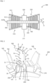
- Fig. 1 schematically shows a gas turbine 300.
- the gas turbine 300 includes a compressor 310, a burner or combustor 320, and a turbine 330.
- the turbine 330 and the compressor 310 may be mechanically integrated to form a rotor 350 which is rotatable about a common rotational axis A350.
- the compressor 310 of the gas turbine 300 may draw air as a working fluid from the environment and compress the drawn air.
- the compressor 310 may be realized as centrifugal compressor or an axial compressor.
- Fig. 1 exemplarily shows a multistage axial compressor which is configured for high mass flows of air.
- the axial compressor may include multiple rotor disks, each carrying a plurality of blades.
- the rotor disks (not shown) are mounted on the shaft 350 and rotate with the shaft about the rotational axis.
- Compressor vanes 313 are arranged downstream of the blades 312. The blades 312 compress the introduced air and deliver the compressed air to the compressor vanes 313 disposed adjacently downstream.
- the plurality of compressor vanes 313 guide the compressed air flowing from compressor blades 312 disposed upstream to compressor blades 312 disposed at a following, downstream stage.
- the air is compressed gradually to a high pressure while passing through the stages of compressor blades 312 and vanes 313.
- the compressed air is supplied to the combustor 320 for combustion of a fuel, such as natural gas, hydrogen, diesel, kerosene, ethanol or similar. Further, a part of the compressed air is supplied as a gaseous cooling fluid to high-temperature regions of the gas turbine 300 for cooling purposes.
- the burner or combustor 320 by use of the compressed air, burns fuel to heat the compressed air.
- the turbine 330 includes a plurality of blade assemblies 200, each comprising a rotor disk 210 to which a plurality of turbine blades 100 are coupled.
- the turbine 330 further includes a plurality of turbine vanes 335.
- Fig. 2 shows a partial view of a blade assembly which will be explained in more detail below.
- the rotor disks 210 are coupled to each other so as to be rotatable together about the rotational axis A350.
- the rotor disks 210 of the turbine and the rotor disks of the compressor may be fastened together by means of a central element such as a bolt to form the rotor 350.
- the turbine blades 100 are coupled to the respective rotor disk 210 and extend radially therefrom.
- the turbine vanes 335 are positioned upstream of the blades 100 of the respective rotor disks 210.
- the turbine vanes are fixed in a stator frame so that they do not rotate about the rotational axis and guide the flow of combustion gas coming from the burner 320 passing through the turbine blades 100.
- the combustion gas is expanded in the turbine 330 and applies a force to the turbine blades 100 which causes the rotor 350 to rotate about the rotational axis A350.
- the compressor 310 may be driven by a portion of the power output from the turbine 330.
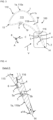
- Fig. 2 shows a blade assembly 200 of the turbine 330.
- the blade assembly includes a rotor disk 210 and a plurality of blades 100.
- the rotor disk 210 may have the form of a ring and, at its outer circumference, includes multiple coupling interfaces 230 for coupling the blades 100 to the disk 210.
- the coupling interfaces 230 may be formed by grooves.
- Fig. 2 shows grooves that have a cross-sectional shape like a firtree.
- the blade assembly 200 includes multiple blades 100.
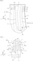
- Fig. 3 exemplarily shows a cross-sectional view of a blade 100.
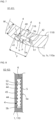
- Fig. 6 shows a blade 100 in a side view.
- each blade 100 may include an airfoil 1, a platform 2, and a root 3.
- the airfoil 1 may extend along radial or span direction R between a platform end 11 and a tip end 12. With regard to an axial or chord direction A, that extends transverse to the radial direction, the airfoil 1 may extend between a leading edge 13 and a trailing edge 14. An outer surface 1a of the airfoil 1, between the leading edge 13 and the trailing edge 14, may define a pressure side surface 1p and a suction side surface 1s being oriented opposite to the pressure side surface 1p.
- the platform 2 may be a substantially plate shaped structure having an expanse with respect to the axial direction A and with respect to a circumferential direction C.
- the circumferential direction C extends transverse to the axial direction A and to the radial direction A.
- the platform 2 is coupled to the platform end 11 of the airfoil 1 and may protrude from the airfoil 1 with respect to the circumferential direction C.
- the platform 2 may include an upper surface 2a oriented towards the tip end 12 of the airfoil 1 and a lower surface 2b oriented opposite to the upper surface 2a.
- the platform 2 may have an end face 2c connecting the upper and lower surfaces 2a, 2b and being oriented in the circumferential direction C.
- the transition surface 2t may be a concave curved surface.
- the root 3 is connected to the lower surface 2b of the platform 2 and protrudes from the lower surface 2b of the platform 2 along the radial direction R.
- the root 3 may include a firtree shaped cross-section.
- the coupling interfaces 230 of the rotor disk 210 and the roots 3 of the blades 100 may have complementary cross-sections.
- the roots 3 and the coupling interfaces 230 are interconnected, i.e., they are engaged and interlocked with each other.
- the blade 100 extends in the radial direction R between a root end 101, e.g., an end of the root 3 facing away from the airfoil 1, and a tip end 102, e.g., being the tip end 12 of the airfoil 1.
- the airfoil 1, the platform 2, and, optionally, the root 3 form a blade body 110.
- An outer surface 110a of the blade body 110 is formed by the outer surface 1a of the airfoil 1, the transition surface 2t, the upper and lower surfaces 2a, 2b and the end face 2c of the platform 2, and, optionally, an outer surface of the root 3.
- the blade body 110 may comprise an inner cavity or void 115.
- the inner cavity 115 is limited by an inner surface 110i of the blade body 110 and serves as a reservoir for receiving a gaseous cooling fluid, e.g., compressed air bleed from the compressor 310.
- a wall thickness W of the blade body 110 is measured from the inner surface 110i to the outer surface 110a of the blade body 110.
- the blade body 110 includes a groove 4 formed in the outer surface 110a of the blade body 110, and a cover 5 covering the groove 4.
- Fig. 4 shows a detailed view of a portion of the blade body 110 of Fig. 3 in the region of the trailing edge 14.
- Fig. 5 shows a side view of the blade body 110 of Fig. 3 when viewed in the viewing direction V depicted in Fig. 3 .
- Fig. 3 shows that the groove 4 may be formed in the pressure side surface 1p of the airfoil 1 in a region adjacent to the trailing edge 14.
- the invention is not limited thereto.
- one or more grooves 4 may be provided also in regions of the airfoil 1 distanced to the trailing edge 14.
- Fig. 6 exemplarily shows that grooves 4 are provided on the pressure side surface 1p of the airfoil 1.
- one or more grooves 4 can also be formed in the suction side surface 1s of the airfoil 1.
- at least one groove 4 is formed in the outer surface 110a of the blade body 110.
- Figs. 7 to 11 show cross-sectional views of grooves 4 formed in the outer surface 110a of the blade body 110.
- the groove 4 may include a bottom 40 and opposite side walls 41, 42 connecting the bottom 40 and the outer surface 110a of the blade body 110.
- the groove 4 may have a generally rectangular cross-section.
- the invention is not limited thereto.
- the groove 4 may also have a polygonal cross-section, or a trapezoidal cross-section, as exemplarily shown in Fig. 10 .
- the groove 4 may include a support 43.
- the support 43 generally, defines a support surface 43a which is oriented such that a normal vector to the support surface 43a has a component perpendicular to a region of the outer surface 110a of the blade body 110 adjacent to the groove 4.
- Figs. 7 and 11 show a groove 4 which support 43 is formed by a step in at least one of the sidewalls 41, 42 of the groove 4.
- both sidewalls 41, 42 include a step.
- only sidewall 41 includes a step.
- Fig. 7 both sidewalls 41, 42 include a step.
- the sidewall 41 may comprise a first portion 41A extending from the bottom 40 of the groove 4 and a second portion 41B extending from the outer surface 110a of the blade body 110.
- the second portion 41B is laterally spaced to the first portion41A in a direction perpendicular to the sidewalls 41, 42.
- a step portion with a step surface forming the support surface 43a extends between and connects the first and second portions 41A, 41B of the sidewall 41.
- the support surface 43a defined by the step may extend parallel to the region of the outer surface 110a of the blade body 110 adjacent to the groove 4.
- the invention is no limited thereto.
- the optional support 43 of the groove 4 may be formed by respective tapering end portions 41E, 42E of the opposing sidewalls 41, 42 of the groove 4, as exemplarily shown in Fig. 10 .
- the support surface 43a may be formed by a surface 41a, 42a of an end portion 41E, 42E of each sidewall 41, 42.
- the end portions 41E, 42E are positioned facing away from the bottom 40 of the groove 4.
- Fig. 10 exemplarily shows that the sidewalls 41, 42 as a whole extend inclined relative to each other and come closer to each other towards the bottom 40 of the groove 4.
- the surfaces 41a, 42a of the sidewalls 41, 42, at least in the end portions 41E, 42E, may define a cross-section of the groove 4 that tappers towards a bottom 40 of the groove.
- the support surface 43a is oriented such that a normal vector to the support surface 43a has a component perpendicular to a region of the outer surface 110a of the blade body 110 adjacent to the groove 4.
- the groove 4 in particular, the bottom 40 of the groove 4 may be formed with at least one of projections 44 and recesses 45.
- the inner cavity 115 may be in fluid communication with the groove 4 via a fluid passage 116 extending between the cavity 115 and the groove 4.
- a fluid passage 116 extending between the cavity 115 and the groove 4.
- multiple passages 116 e.g., in the form of holes, may be provided.
- a depth h of the groove 4 is measured from the outer surface 110a of the blade body 110 to a bottom 40 of the groove 4.
- the wall thickness W of the blade body 110 may lie within a range between 1.5 and 4 times, optionally, between 1.5 and 2 times, of the depth h of the groove 4.
- a width F of the groove 4, measured between the opposing sidewalls 41, 42 at the outer surface 110a of the blade 110 may lie in a range between 0.2 to 10 times of the wall thickness W, in particular, in a range between 1 to 3 times of the wall thickness W. If the support 43 is provided as a step, a depth h1 of the first portion 41A of the side wall 41 may be in a range between 1 to 6 times, in particular, 1.5 to 3 times of a diameter d of the fluid passage 116.
- the groove 4 may extend meandering on the outer surface 110a of the blade body 110.
- the groove 4 may have first sections 4A that extend substantially along the radial direction R and/or substantially parallel to the trailing edge 14 on the outer surface 1a of the airfoil 1, and one or more second sections 4B, wherein one second section 4B connects two first sections 4A.
- the groove 4 extends generally straight, as exemplarily shown in Fig. 6 .
- the groove 4 may be connected to the outer surface 110a of the blade body 110 by one or more outlet passages 117 extending between the groove 4 and the outer surface 110a of the blade body 110.
- a plurality of outlet passages 117 may extend between the trailing edge 117 and the groove 4, as schematically shown in Fig. 5 .
- the cover 5 is a part separate from the blade body 110 but joined to the blade body 110, for example, by brazing, diffusion bonding, or welding, or another material bonding method.
- the cover 5 is positioned on the blade body 110 such that it covers the groove 4 and such that the cover 5 and the groove 4, together, define a cooling channel 6.
- the cooling fluid received in the cavity 115 enters the cooling channel 6 via the one or more passages 116 and flows through the cooling channel 6 where it receives heat from the cover 5 and the walls 40, 41, 42 of the groove 4.
- the cooling fluid is discharged to the outer surface 110a of the blade body 110 through the outlet passages 117.
- the passages 116 may extend inclined relative to the cover 5 and so that a central axis of the passage 116 intersects the cover 5. Thereby, the cooling fluid discharged into the channel 6 impinges to the cover which further promotes heat transfer via the cover 5. It should be noted that, alternatively to multiple, inclined passages as shown in Fig. 5 , one single passage 116 of larger diameter may be provided. In this case, an impingement effect is reduced or not present. Instead, heat transfer via the cover 5 is promoted via convective cooling by the fluid flowing in the channel 6.
- the cover 5 is a plate or strip shaped part comprising an outer surface 5a and an opposite inner surface 5b.
- the inner surface 5b of the cover 5 faces the groove 4, in particular, the outer surface 5a is positioned to be substantially flush with the outer surface 110a of the blade body 110 as exemplarily shown in Figs. 4 and 7 to 11 .
- the cover 5 may be positioned within the groove 4 and so that the outer surface 5a of the cover 5 and the outer surface 110a of the blade body 110 form a continuous surface.
- the inner surface 5b of the cover 5 may be in contact with or supported by the support surface 43a of the support 43 of the groove 4.
- opposite end faces 5e that connect the inner and outer surface 5a, 5b of the cover 5 may be in contact with and supported by those tapering surfaces 41a, 42a forming the support surface 43.
- the cover 5 may have a thickness P, measured between the inner and the outer surface 5a, 5b, in a range between 0.5 mm and 2.0 mm, preferably between 0.8 mm and 1.2 mm.
- the cover 5 may have a very small wall thickness P which promotes heat transfer between the inner and the outer surface 5a, 5b. Further, thermally introduced stress is reduced due to the small thickness P of the cover 5 resulting in a decreased temperature difference across the cover 5.
- the depth h of the groove 4 may be within a range of 1.5 to 5 times, in particular, 1.7 to 2.5 times of the thickness P of the cover 5.
- a width L of the support surface 43a, measured perpendicular to the spacing direction of the sidewalls 41, 42 of the groove 4 may be in a range between 0 to 1.5, in particular, between 0 to 0.5 of the thickness P of the cover 5.
- the inner surface 5b of the cover 5, optionally, may be formed with at least one of projections 52 and recesses 53.
- the cover 5 may include a spacer 51 protruding from the inner surface 5b of the cover 5, as schematically shown in Fig. 11 . As shown in Fig. 11 , the spacer 51 extends into the groove 4 and contacts the bottom 40 of the groove 4 to hold the outer surface 5a. Alternatively, it would also be possible that the spacer 51 contacts a support surface 43a, if provided.
- FIG. 9 schematically shows a blade body 110 which groove 4 has straight sidewalls 41, 42, and the cover 5 extends between the sidewalls 41, 42 without being supported by a spacer 51 or a support 43.
- the cover 5, optionally, may be a single continuous part covering the groove 4 at its complete extent. Alternatively, multiple covers 5 may be positioned adjacent along the extent of the groove 4 to cover the groove 4. Generally, the cover 5 may be adapted to the course and extent of the groove 4.
- the cover 5 is made of a metal material, e.g. a Nickel or Cobalt based high temperature alloy, in particular, an alloy suitable for additive manufacturing. For example, IN792SX, CM247LC, Hastelloy-X, Haynes 230 or similar may be used.
- Fig. 12 shows a flowchart of a method M for manufacturing a blade 100 for a gas turbine 300.
- the method M may be used to manufacture one of the blades 100 described above. Therefore, the method M, by way of example, will be explained referring to the blades 100 discussed above.
- step M1 the blade body 110 is formed. This may, hence, include forming the airfoil 1, the platform 2, and the root 3. Step M1 may include casting the blade body 110, e.g., in a conventionally cast (CC), a directionally solidified (DS), or single crystal (SX) cast process.
- the blade body 110 may be made of a Nickel or Cobalt based high temperature alloy, such as, e.g., IN792SX, CM247LC, or similar.
- Step M2 includes forming the groove 4 in the outer surface 110a of the blade body 110, e.g., in the airfoil 1 or in the platform 2.
- Step M2 may form part of step M1. That is, the groove 4 may be formed, for example, in the casting process in which the blade body 110 is generated.
- the groove 4 optionally may be post processed with an subtractive method, such as grinding, for example, to adapt surface quality to the desired needs.
- the blade body 110 may be generated in step M1 with a continuous, closed outer surface 110a, and the groove 4 may be formed in step M2 subsequently by applying a subtractive manufacturing process, such as milling, grinding, die sinking, etching or similar, to the outer surface 110a of the blade body 110, that is, after forming the blade body 110.
- a subtractive manufacturing process such as milling, grinding, die sinking, etching or similar
- the optional protrusions 44 and/or recesses 45 may be formed in the groove 4.
- step M21 the fluid passage or passages 116 between the inner cavity 115 and the groove 4 may be formed.
- step M21 if provided, also the outlet passage 117 may be formed. It is to be noted that forming the respective passage 116, 117 may include drilling a hole or otherwise generating a passage between the groove 4 and the cavity 115 or the groove and the outer surface 110a in an subtractive process. Alternatively, the respective passage 116, 117 may be generated in step M1 of forming the blade body 110, i.e., in the casting process process.
- a removable spacing structure (not shown) is introduced into the groove 4.
- the spacing structure may be a framework of a material that can be melted or thermally destroyed in a temperature range in which the structural properties of blade body 110 and the cover 5 are not affected, or of a material that can be chemically dissolved or destroyed by a liquid or gaseous agent.
- the spacing structure may be made of a thermoplastic material, a starch based material or similar.
- the cover 5 is positioned on the blade body 110 such that it covers the groove 4 and such that the outer surface 5a of the cover 5 and the outer surface 110a of the blade body 110 form a continuous surface.
- the cover 5 may be introduced into the groove 4. If provided, the cover 5 may be placed in contact with the optional support surface 43a. Additionally, or alternatively, the spacer 51 of the cover 5 may be placed in contact with the bottom 40 or the support surface 43a of the groove 4. If provided, the cover 5 may be placed, additionally, or alternatively, on the spacing structure. After positioning the cover 5 in the groove 4, the inner surface 5b of the cover 5 faces the bottom 40 of the groove 4.
- step M4 the cover 5 is joined to the blade body 110 so that the cover 5 and the groove 4 define the cooling channel 6.
- joining the cover 5 to the blade body 110 may include material bonding.
- the cover 4 and the blade body may be brazed together, diffusion bonded to each other, or weld together. Welding, for example, may include laser welding, arc welding, or electron beam welding.
- the outer surface 5a of the cover may be treated, e.g. in a subtractive process, so that it is matched with the outer surface 110a of the blade body 110.
- material of the cover 5 protruding over the outer surface 110a of the blade body 110 may be removed and/or a surface roughness of the outer surfaces 5a, 110a of the cover 5 and/or the blade body 110 may be adjusted.
- the spacing structure may be removed thermally or chemically from the channel 6. This may include heating the blade to a temperature sufficient to melt or destroy the support structure and purge the support structure from the channel 6. Alternatively, a solving agent may be introduced into the channel 6 to dissolve or otherwise chemically remove the support structure.
- one or more coating layers may be applied to the outer surface of the blade 100, formed by the outer surface 110a of the blade body 110 and the outer surface 5a of the cover. This may include, for example, applying a coating to the outer surface of the blade 100.
- a MCrAlY material or other suitable material as bondcoat may be applied by a low pressure plasma spray (LPPS), a vacuum plasma spray (VPS), an air plasma spray (APS), or high velocity oxy fuel (HVOF) process.
- LPPS low pressure plasma spray
- VPS vacuum plasma spray
- APS air plasma spray
- HVOF high velocity oxy fuel
- M high velocity oxy fuel
- a topcoat may be applied to the coating.
- a single or multi-layered ceramic e.g., Yttrium stabilized zirconium (YSZ) may be applied by LPPS or APS.
- the cover 5 is provided as a separate component which is joined to the blade body 110 after generating the blade body 110, a thin wall thickness, defined by the thickness P of the cover 5, between the cooling channel 6 and the outer surface 5a, 110a of the blade 100 can be realized. Thereby, the temperature difference across the cover 5 and, hence, stress within the cover 5 is reduced. This helps to increase lifetime of the blade 100. Due to the reduced wall thickness P of the cover 5, heat transfer between the outer surface 5a, 110a of the blade 100 and the cooling fluid flowing in the channel 5 is increased. Hence, lower mass flow rates of cooling fluid are necessary to achieve a given cooling rate. This helps to improve the overall efficiency of the gas turbine 300 because less compressed air has to be bleed from the compressor 310 for cooling purposes. Further, manufacturing of the blade 100 is eased since complicated and failure prone cores for defining a closed channel beneath the outer surface of the blade 100 can be omitted.
Landscapes
- Engineering & Computer Science (AREA)
- Mechanical Engineering (AREA)
- General Engineering & Computer Science (AREA)
- Architecture (AREA)
- Turbine Rotor Nozzle Sealing (AREA)
Abstract
A method (M) for manufacturing a blade (100) for a gas turbine (300) includes
forming (M1) a blade body (110);
forming (M2) a groove (4) in an outer surface (110a) of the blade body (110);
positioning (M3) a cover (5) on the blade body (110) such that it covers the groove (4) and such that an outer surface (5a) of the cover (5) forms a continuous surface with the outer surface (110a) of the blade body (110); and
joining (M4) the cover (5) to the blade body (110) so that the cover (5) and the groove (4) define a cooling channel (6).
forming (M1) a blade body (110);
forming (M2) a groove (4) in an outer surface (110a) of the blade body (110);
positioning (M3) a cover (5) on the blade body (110) such that it covers the groove (4) and such that an outer surface (5a) of the cover (5) forms a continuous surface with the outer surface (110a) of the blade body (110); and
joining (M4) the cover (5) to the blade body (110) so that the cover (5) and the groove (4) define a cooling channel (6).
A blade (100) for a gas turbine (300) and a gas turbine (300) are also provided.

Description
- The present invention relates to a method for manufacturing a blade for a gas turbine, to a blade for a gas turbine, and to a gas turbine.
- Blades of gas turbines, in particular, blades in a turbine part of the gas turbine, are subject to high thermal loads. Therefore, it is common to cool the blades by means of a cooling fluid, such as compressed air delivered by a compressor of the gas turbine. The cooling fluid, typically, is conducted to an interior cavity of the blade and, from there, distributed to various cooling channels.
- Document
US 6 974 308 B2 discloses a turbine blade manufactured in a casting process. The turbine blade includes an airfoil that is formed with an outer wall, wherein the outer wall includes an outer surface defining a suction side and a pressure side, and an inner surface that defines a cavity. A plurality of cooling channels is formed within the massive material between the inner and outer surface of the airfoil. - To improve heat transfer between the cooling fluid flowing in the cooling channels, it would be desirable to reduce a wall thickness between the outer surface of the blade and the cooling channel. However, manufacturing tolerances of typical casting processes limit the minimum possible wall thickness.
- It is one of the objects of the present invention to provide improved solutions for cooling a blade of a gas turbine. In particular, it is an object to provide a blade with a cooling channel that can be manufactured with reduced wall thickness more reliably.
- To this end, the present invention provides a method for manufacturing a blade for a gas turbine in accordance with
claim 1, a blade in accordance withclaim 14, and a gas turbine in accordance with claim 15. - According to a first aspect of the invention, a method for manufacturing a blade for a gas turbine includes forming a blade body, forming a groove in an outer surface of the blade body, positioning a cover on the blade body such that it covers the groove and such that an outer surface of the cover forms a continuous surface with the outer surface of the blade body, and joining the cover to the blade body so that the cover and the groove define a cooling channel.
- According to a second aspect of the invention, a blade for a gas turbine includes a blade body having an outer surface in which a groove is formed, and a cover positioned such that it covers the groove and such that an outer surface of the cover forms a continuous surface with the outer surface of the blade body, wherein the cover is joined to the blade body, and wherein the cover and the groove define a cooling channel. The blade according to this aspect of the invention, for example, may be manufactured using the method according to the first aspect of the invention.
- According to a third aspect of the invention, a gas turbine includes a blade according to the second aspect of the invention.
- It is one of the ideas of the present invention to form a blade body with an open groove at its outer surface, first, and to subsequently join a cover to the blade body that covers the groove so that a cooling channel is limited by the walls of the groove and the cover. The groove may comprise a bottom and opposing sidewalls extending between the bottom of the groove and the outer surface of the blade body. The cover, which may, for example, be generally strip shaped, is positioned on the blade body so that it covers the groove and so that its outer surface is flush or substantially flush with the outer surface of the blade body. For example, the cover may be positioned, at least partially, within the groove, in particular, so that it protrudes into the groove, while its outer surface and the outer surface of the blade form a continuous surface. In this context, a "continuous surface" is not limited to a perfectly flush arrangement of the outer surface of the cover and the outer surface of the blade body but also includes configurations, in which the outer surface of the cover slightly protrudes over the outer surface of the blade body, e.g., by a height being smaller than 5 % of a wall thickness of the cover.
- The cooling channel limited by the walls or wall surfaces of the groove and an inner surface of the cover has a closed circumference, e.g., a rectangular or substantially rectangular circumference. Since the groove is formed as an open groove, tolerance based limits related to a minimum possible wall thickness are avoided. The thickness of the cover, i.e. a distance between an inner surface and the outer surface of the cover, can be dimensioned according to the actual heat transfer needs, since the cover is manufactured as a separate component and joined subsequently to the blade body.
- Hence, heat transfer between a cooling fluid flowing in the cooling channel and an outer surface of the blade can be improved. This results in various benefits. In particular, thermal stress within the wall of the blade is reduced due to a lower temperature difference across the wall resulting from the lower wall thickness. Accordingly, lifetime of the blade is increased. Further, due to the increased heat transfer between the cooling fluid flowing in the cooling channel and the outer surface of the blade, a mass flow of the cooling fluid necessary to achieve a given heat transfer rate can be reduced. Thereby, the overall efficiency of the gas turbine is increased.
- Since the cover is a separate part that is subsequently joined to the blade body, the freedom in design to adjust cooling to the actual needs, e.g., to locally high heat loads, is increased. Further, replacing the cover, e.g., in a repairing process, is eased.
- Within the scope of the present invention, the term "blade" is intended to cover both, a rotating blade, which may be coupled, for example, to a rotating disk of the gas turbine, and a stationary vane, which may be coupled, for example, to a stator frame of the gas turbine.
- Further embodiments of the present disclosure are subject of the further subclaims and the following description, referring to the drawings.
- According to some embodiments, the blade body may be formed to include an airfoil extending along a radial direction and a platform protruding along a circumferential direction from a platform end of the airfoil, wherein an outer surface of the airfoil and an outer surface of the platform form the outer surface of the blade body. Optionally, the blade body may be formed to additionally include a root protruding from the platform in the radial direction on a side opposite to the airfoil. The root, for example, may have a firtree shaped cross-section, and, generally, is configured to couple the blade to a rotor disk or to a frame, e.g. in case of a vane.
- According to some embodiments, the airfoil may be formed to extend in a chord or axial direction between a leading edge and a trailing edge, wherein a pressure side surface and a suction side surface of the airfoil meet at the leading and the trailing edge, and wherein the groove is formed in at least one of the pressure side surface and the suction side surface adjacent to the trailing edge. That is, a cooling channel formed beneath the outer surface of the airfoil is formed in a region very close to the trailing edge. "Adjacent to the trailing edge" may be understood as a distance, at each radial position of the airfoil, from the physical end of the airfoil formed by the trailing edge, the distance being in a range between 1 % and 20 % of a total length of the airfoil in the chord direction at the respective radial position. The total length of the airfoil in the chord direction, in this context, may be defined as a length of a skeleton line connecting the leading and the trailing edge and being equally distanced to each of the pressure and the suction side surface. Since the cooling channel is formed by joining the cover to the airfoil having the groove, it is easier to place the cooling channel closer to the trailing edge, compared to forming the cooling channel exclusively in a casting process. In particular, airfoils with a small wedge angle at the trailing edge can easier be realized. For example, the airfoil may be formed with a wedge angle at the trailing edge in a range between 7° and 17°.
- According to some embodiments, forming the blade body may include casting the blade body. For example, a conventionally cast (CC), a directionally solidified (DS), or single crystal (SX) cast process may be carried out to form the blade body.
- According to some embodiments, the groove may be formed in the step of forming the blade body. For example, the grooves may be formed during the casting process. In other words, the blade body may be formed to already include the grooves. Optionally, the grooves may additionally be treated after forming the blade body, e.g. a surface treatment of the walls of the groove may be carried out, which may, for example, include at least one of grinding, die sinking, or similar. One advantage of forming the groove within the forming process of the blade body is that the process time can be reduced. Further, as the groove opens to the outer surface of the blade body, it is easy to integrate the step of forming the grooves in a casting process.
- According to some embodiments, the groove may also be formed by applying an subtractive manufacturing process, such as grinding, die sinking, etching or similar, to the outer surface of the blade body after forming the blade body. Hence, the blade body can be formed first, e.g., in a casting process, and the groove is formed subsequently by an subtractive method. This provides the benefit that the forming step of the blade body can be further eased. Additionally, subtractive processes can be carried out very precisely and with low manufacturing tolerances.
- According to some embodiments, the blade body may be formed to have an inner surface defining an inner cavity or void, wherein a wall thickness of the blade body is measured from the inner surface to the outer surface of the blade body. The inner cavity or void may, for example, extend within the airfoil and/or within a root of the blade body and is configured to receive a gaseous cooling fluid, such as compressed air. The wall thickness may be defined on each point of the inner and outer surface of the blade body as a shortest distance between the inner and the outer surface at the respective point.
- According to some embodiments, the wall thickness may be within a range between 1.5 and 4 times, optionally between 1.5 and 2 times, of a depth of the groove measured from the outer surface of the blade body to a bottom of the groove. Hence, a ratio W/h, where "W" is the wall thickness and "h" is the depth of the groove, may be within a range of 1.5 to 4, in particular, between 1.5 and 2.
- According to some embodiments, the method may further include forming a fluid passage extending between the cavity and the groove. The inner cavity or void, hence, may be formed to be in fluid communication with the groove. For example, the blade body may be formed to include a communication channel extending between the groove and the cavity, or a communication hole may be drilled to extend from the groove to the cavity. Of course, multiple fluid passages, e.g., in the form of holes, may be formed in this step.
- According to some embodiments, the method may include forming an outlet passage extending between the groove and the outer surface of the blade body. Through the outlet passage, the cooling fluid flowing in the cooling channel can be discharged to the outer surface of the blade body. For example, the outlet passage may be drilled.
- According to some embodiments, the groove may be formed with a support defining a support surface being oriented such that a normal vector to the support surface has a component perpendicular to a region of the outer surface of the blade body adjacent to the groove. As already explained above, irrespective of having a support or not, the groove may comprise a bottom and opposing sidewalls extending between the bottom of the groove and the outer surface of the blade body. The support may be integrally formed with at least one of the bottom and one or both of the sidewalls. The support, generally, may be a physical structure or element that includes a surface that is oriented parallel or inclined to the portion of the outer surface that surrounds the groove or extends adjacent to the groove. Hence, a normal vector to the support surface has a component perpendicular to the region of the outer surface of the blade body adjacent to the groove. This allows placing the cover on the support surface, for example, before joining it to the blade body. Thereby, positioning and joining of the cover is eased.
- According to some embodiments, the support may be formed by a step in a sidewall of the groove, the support surface connecting two laterally spaced portions of the sidewall. That is, the sidewall may comprise a first portion extending from the bottom and a second portion extending from the outer surface of the blade body, wherein the second portion is spaced to the first portion in a direction perpendicular to the sidewalls, and wherein a step portion with the step surface extends between and connects the first and second portions of the sidewall. A distance between the first portion of the sidewall and the opposing sidewall is smaller than a distance between the second portion of the sidewall and the opposing sidewall. Hence, the second portion is laterally spaced to the first portion. Optionally, the support surface may extend parallel to the region of the outer surface of the blade adjacent to the groove. The step provides the advantage that it reliably and stably supports the cover.
- According to some embodiments, the support may be formed by respective end portions of opposing sidewalls of the groove, wherein the support surface is formed by a surface of each sidewall, wherein the surfaces of the sidewalls, at least in the end portions, define a cross-section of the groove that tapers towards a bottom of the groove. The end portions of the sidewalls are opposite to the bottom. In other words, the end portions of the side walls are adjacent to or extend from the outer surface of the blade body. The surfaces of the sidewalls, in the end portions, may, for example, extend tapering towards the bottom of the groove. This may include, for example, that the surfaces of the sidewalls, in the end portions, extend straight or planar, or that they extend with a concave curvature. Also in these configurations, a normal vector to the support surface, which is formed by the surfaces of the sidewalls in their end portions, has a component perpendicular to the region of the outer surface of the blade body adjacent to the groove. This allows placing the cover on the support surface, for example, before joining it to the blade body. Thereby, positioning and joining of the cover is eased. Tapering end portions of the sidewall provides the advantage that they reliably and stably support the cover. Further, they help in centering the cover relative to the groove.
- According to some embodiments, the cover may include a spacer protruding from an inner surface of the cover, wherein positioning the cover on the blade body may include introducing the spacer into the groove so that the spacer contacts a bottom or a support surface of the groove to hold the outer surface of the cover in a position in which it forms a continuous surface with the outer surface of the blade body. Additionally or alternatively to the support of the groove, the cover may include a protrusion, e.g. a rib, protruding from its inner surface that faces the bottom of the groove, when the cover is placed on the blade body. The spacer may be contacted to the bottom of the groove or to a support surface provided within one of the sidewalls, e.g., a support surface of a support as described above. The protrusion, thus, serves as a spacer, that defines a distance between the bottom or the support surface and the outer surface of the cover, and that holds the cover in place, for example, during joining.
- According to some embodiments, the method may include introducing a spacing structure into the groove, wherein positioning the cover on the blade body includes positioning the cover on the spacing structure so that the spacing structure holds the cover in a position in which the outer surface of the cover forms a continuous surface with the outer surface of the blade body, and thermally or chemically removing the spacing structure after joining the cover to the blade body. The spacing structure, for example, may include stands, ribs, pins or other spacers, that are placed in the groove and dimensioned so that they hold the cover in a position in which the outer surface of the cover is substantially flush with the outer surface of the blade body. The spacing structure can be made, for example, from a plastic material, a material including natural fibers, a wax, or similar. After placing the cover on the support structure and joining the cover to the blade body, the support structure is removed thermally or chemically. This may include heating the blade body to a temperature above the melting temperature or combustion point of the support structure and purging the melted or burned structure out of the channel. Alternatively, removing the support structure may include introducing a solvent, e.g., in liquid form, into the channel, wherein the solvent dissolves or liquidates the support structure. The liquid support structure and the solvent are purged out of the channel finally. Using a support structure provides the advantage that the cross-sectional area of the channel can be maximized.
- According to some embodiments, the cover may have a thickness in a range between 0.5 mm and 2.0 mm. The thickness may be measured between the inner and the outer surface of the cover. The range of 0.5 mm to 2.0 mm defines a relatively small wall thickness of the cover which allows for good heat transfer. Optionally, the cover may have a thickness in a range between 0.8 mm and 1.2 mm. This range represents a good compromise between mechanical stiffness and heat transfer.
- According to some embodiments, joining the cover to the blade body may include positive substance joining, respective material bonding. For example, joining may include brazing, diffusion bonding, or welding the cover and the blade body together. Welding, for example, may include laser welding, arc welding, or electron beam welding.
- According to some embodiments, at least one of the groove and an inner surface of the cover is formed with at least one of projections and recesses. Those recesses and/or projections in the inner surface of the cover and/or the surface of the groove increase the effective area available for heat transfer. Hence, heat transfer can be further improved.
- According to some embodiments, the blade body may be made of a Nickel or Cobalt based high temperature alloy, such as, e.g., IN792SX, CM247LC, or similar.
- According to some embodiments, the cover may be made of a Nickel or Cobalt based high temperature alloy, in particular, an alloy suitable for additive manufacturing. For example, Hastelloy-X,
Haynes 230, IN792SX, CM247LC, or similar may be used. - According to some embodiments, the method may include applying a coating to the outer surface of the cover and the outer surface of the blade body. For example, a MCrAlY material or other suitable material as bondcoat may be applied by a low pressure plasma spray (LPPS), an air plasma spray (APS), a vacuum plasma spray (VPS), or high velocity oxy fuel (HVOF) process. The letter "M" in "MCrAlY" is a placeholder for Co, Ni, or NiCo.
- According to some embodiments, the method may include applying a topcoat to the coating. For example, a single or multi-layered ceramic, e.g., Yttrium stabilized zirconium (YSZ), may be applied by LPPS. A further method for applying a topcoat would be, for example, APS.
- According to some embodiments, the gas turbine may comprise a compressor configured to compress a working fluid, a burner receiving compressed working fluid from the compressor and configured to burn a fuel to heat the working fluid, and a turbine including the turbine blade assembly, wherein the turbine stage is configured to expand the working fluid causing the turbine blade assembly to rotate. Hence, the blade assembly may form part of the turbine. As a working fluid, the compressor may suck air from the environment, and the compressed air may be used for combustion of the fuel in the combustor or burner. As a fuel, liquid fuel, such as kerosene, diesel, ethanol, or similar may be used. Alternatively, gaseous fuel such as natural gas, fermentation gas, hydrogen, or similar can be used.
- The features and advantages described herein with respect to one aspect of the invention are also disclosed for the other aspects and vice versa.
- With respect to directions and axes, in particular, with respect to directions and axes concerning the extension or expanse of physical structures, within the scope of the present invention, an extent of an axis, a direction, or a structure "along" another axis, direction, or structure includes that said axes, directions, or structures, in particular tangents which result at a particular site of the respective structure, enclose an angle which is smaller than 45 degrees, preferably smaller than 30 degrees and in particular preferable extend parallel to each other.
- With respect to directions and axes, in particular with respect to directions and axes concerning the extension or expanse of physical structures, within the scope of the present invention, an extent of an axis, a direction, or a structure "crossways", "across", "cross", or "transversal" to another axis, direction, or structure includes in particular that said axes, directions, or structures, in particular tangents which result at a particular site of the respective structure, enclose an angle which is greater or equal than 45 degrees, preferably greater or equal than 60 degrees, and in particular preferable extend perpendicular to each other.
- For a more complete understanding of the present invention and advantages thereof, reference is now made to the following description taken in conjunction with the accompanying drawings. The invention is explained in more detail below using exemplary embodiments, which are specified in the schematic figures of the drawings, in which:
- Fig. 1
- schematically illustrates a cross-sectional view of a gas turbine according to an embodiment of the invention.
- Fig. 2
- shows a perspective, partial view of a blade assembly including blades according to an embodiment of the invention.
- Fig. 3
- schematically illustrates a cross-sectional view of a turbine blade according to an embodiment of the invention.
- Fig. 4
- shows a detailed view of the area marked by letter Z in
Fig. 3 - Fig. 5
- schematically illustrates a side view of the blade shown in
Fig. 3 . - Fig. 6
- schematically illustrates a side view of a turbine blade according to a further embodiment of the invention.
- Fig. 7
- shows a schematic cross-sectional view of the blade of
Fig. 6 taken along line X1-X1 inFig. 6 . - Fig. 8
- shows a schematic cross-sectional view of the blade of
Fig. 6 taken along line X2-X2 inFig. 6 . - Fig. 9
- schematically illustrates a partial cross-sectional view of a turbine blade according to a further embodiment of the invention.
- Fig. 10
- schematically illustrates a partial cross-sectional view of a turbine blade according to a further embodiment of the invention.
- Fig. 11
- schematically illustrates a partial cross-sectional view of a turbine blade according to a further embodiment of the invention.
- Fig. 12
- illustrates a flowchart of a method for manufacturing a blade of a turbine according to an embodiment of the invention.
- In the figures like reference signs denote like elements unless stated otherwise.
-
Fig. 1 schematically shows agas turbine 300. Thegas turbine 300 includes acompressor 310, a burner orcombustor 320, and aturbine 330. Theturbine 330 and thecompressor 310 may be mechanically integrated to form arotor 350 which is rotatable about a common rotational axis A350. - The
compressor 310 of thegas turbine 300 may draw air as a working fluid from the environment and compress the drawn air. Thecompressor 310 may be realized as centrifugal compressor or an axial compressor.Fig. 1 exemplarily shows a multistage axial compressor which is configured for high mass flows of air. The axial compressor may include multiple rotor disks, each carrying a plurality of blades. The rotor disks (not shown) are mounted on theshaft 350 and rotate with the shaft about the rotational axis.Compressor vanes 313 are arranged downstream of theblades 312. Theblades 312 compress the introduced air and deliver the compressed air to thecompressor vanes 313 disposed adjacently downstream. The plurality ofcompressor vanes 313 guide the compressed air flowing fromcompressor blades 312 disposed upstream tocompressor blades 312 disposed at a following, downstream stage. The air is compressed gradually to a high pressure while passing through the stages ofcompressor blades 312 andvanes 313. - The compressed air is supplied to the
combustor 320 for combustion of a fuel, such as natural gas, hydrogen, diesel, kerosene, ethanol or similar. Further, a part of the compressed air is supplied as a gaseous cooling fluid to high-temperature regions of thegas turbine 300 for cooling purposes. The burner orcombustor 320, by use of the compressed air, burns fuel to heat the compressed air. - As schematically shown in
Fig. 2 , theturbine 330 includes a plurality ofblade assemblies 200, each comprising arotor disk 210 to which a plurality ofturbine blades 100 are coupled. Theturbine 330 further includes a plurality ofturbine vanes 335.Fig. 2 shows a partial view of a blade assembly which will be explained in more detail below. Generally, therotor disks 210 are coupled to each other so as to be rotatable together about the rotational axis A350. For example, therotor disks 210 of the turbine and the rotor disks of the compressor may be fastened together by means of a central element such as a bolt to form therotor 350. Theturbine blades 100 are coupled to therespective rotor disk 210 and extend radially therefrom. Theturbine vanes 335 are positioned upstream of theblades 100 of therespective rotor disks 210. The turbine vanes are fixed in a stator frame so that they do not rotate about the rotational axis and guide the flow of combustion gas coming from theburner 320 passing through theturbine blades 100. The combustion gas is expanded in theturbine 330 and applies a force to theturbine blades 100 which causes therotor 350 to rotate about the rotational axis A350. Thecompressor 310 may be driven by a portion of the power output from theturbine 330. -
Fig. 2 shows ablade assembly 200 of theturbine 330. As explained above, the blade assembly includes arotor disk 210 and a plurality ofblades 100. - The
rotor disk 210, generally, may have the form of a ring and, at its outer circumference, includesmultiple coupling interfaces 230 for coupling theblades 100 to thedisk 210. As exemplarily shown inFig. 2 , the coupling interfaces 230 may be formed by grooves. As an example,Fig. 2 shows grooves that have a cross-sectional shape like a firtree. - As shown in
Fig. 2 , theblade assembly 200 includesmultiple blades 100.Fig. 3 exemplarily shows a cross-sectional view of ablade 100.Fig. 6 shows ablade 100 in a side view. As shown inFigs. 2 and6 , eachblade 100 may include anairfoil 1, aplatform 2, and aroot 3. - The
airfoil 1 may extend along radial or span direction R between aplatform end 11 and atip end 12. With regard to an axial or chord direction A, that extends transverse to the radial direction, theairfoil 1 may extend between aleading edge 13 and a trailingedge 14. Anouter surface 1a of theairfoil 1, between theleading edge 13 and the trailingedge 14, may define apressure side surface 1p and asuction side surface 1s being oriented opposite to thepressure side surface 1p. - As schematically shown in
Fig. 2 , theplatform 2 may be a substantially plate shaped structure having an expanse with respect to the axial direction A and with respect to a circumferential direction C. The circumferential direction C extends transverse to the axial direction A and to the radial direction A. Theplatform 2 is coupled to theplatform end 11 of theairfoil 1 and may protrude from theairfoil 1 with respect to the circumferential direction C. As depicted by way of example inFig. 2 , theplatform 2 may include anupper surface 2a oriented towards thetip end 12 of theairfoil 1 and alower surface 2b oriented opposite to theupper surface 2a. Further, theplatform 2 may have anend face 2c connecting the upper andlower surfaces - The
outer surface 1a of theairfoil 1, in particular, thepressure side surface 1p and thesuction side surface 1s, each may be connected to theupper surface 2a of theplatform 2 via atransition surface 2t. As exemplarily shown inFig. 2 , thetransition surface 2t may be a concave curved surface. - The
root 3 is connected to thelower surface 2b of theplatform 2 and protrudes from thelower surface 2b of theplatform 2 along the radial direction R. As exemplarily shown inFig. 2 , theroot 3 may include a firtree shaped cross-section. Generally, the coupling interfaces 230 of therotor disk 210 and theroots 3 of theblades 100 may have complementary cross-sections. As shown inFig. 2 , theroots 3 and the coupling interfaces 230 are interconnected, i.e., they are engaged and interlocked with each other. - Hence, generally, the
blade 100 extends in the radial direction R between aroot end 101, e.g., an end of theroot 3 facing away from theairfoil 1, and atip end 102, e.g., being thetip end 12 of theairfoil 1. Theairfoil 1, theplatform 2, and, optionally, theroot 3 form ablade body 110. Anouter surface 110a of theblade body 110 is formed by theouter surface 1a of theairfoil 1, thetransition surface 2t, the upper andlower surfaces end face 2c of theplatform 2, and, optionally, an outer surface of theroot 3. - As shown in
Fig. 3 , theblade body 110, in particular, theairfoil 1, may comprise an inner cavity or void 115. Theinner cavity 115 is limited by aninner surface 110i of theblade body 110 and serves as a reservoir for receiving a gaseous cooling fluid, e.g., compressed air bleed from thecompressor 310. A wall thickness W of theblade body 110 is measured from theinner surface 110i to theouter surface 110a of theblade body 110. - As further shown in
Fig. 3 , theblade body 110 includes agroove 4 formed in theouter surface 110a of theblade body 110, and acover 5 covering thegroove 4.Fig. 4 shows a detailed view of a portion of theblade body 110 ofFig. 3 in the region of the trailingedge 14.Fig. 5 shows a side view of theblade body 110 ofFig. 3 when viewed in the viewing direction V depicted inFig. 3 . -
Fig. 3 , by way of example only, shows that thegroove 4 may be formed in thepressure side surface 1p of theairfoil 1 in a region adjacent to the trailingedge 14. The invention, however, is not limited thereto. As schematically shown inFigs. 3 and6 , one ormore grooves 4 may be provided also in regions of theairfoil 1 distanced to the trailingedge 14.Fig. 6 exemplarily shows thatgrooves 4 are provided on thepressure side surface 1p of theairfoil 1. Additionally, or alternatively, it is also possible to provide agroove 4 in theplatform 2, e.g., in the upper orlower surface platform 2. It should be understood that one ormore grooves 4 can also be formed in thesuction side surface 1s of theairfoil 1. Generally, at least onegroove 4 is formed in theouter surface 110a of theblade body 110. -
Figs. 7 to 11 show cross-sectional views ofgrooves 4 formed in theouter surface 110a of theblade body 110. Generally, thegroove 4 may include a bottom 40 andopposite side walls outer surface 110a of theblade body 110. As exemplarily shown inFigs. 3, 4 , and9 , thegroove 4 may have a generally rectangular cross-section. However, the invention is not limited thereto. As schematically shown inFig. 7 , thegroove 4 may also have a polygonal cross-section, or a trapezoidal cross-section, as exemplarily shown inFig. 10 . - Optionally, the
groove 4 may include asupport 43. Thesupport 43, generally, defines asupport surface 43a which is oriented such that a normal vector to thesupport surface 43a has a component perpendicular to a region of theouter surface 110a of theblade body 110 adjacent to thegroove 4.Figs. 7 and11 , by way of example, show agroove 4 which support 43 is formed by a step in at least one of thesidewalls groove 4. InFig. 7 , bothsidewalls Fig. 11 , only sidewall 41 includes a step. As visible best inFig. 11 , thesidewall 41 may comprise afirst portion 41A extending from the bottom 40 of thegroove 4 and asecond portion 41B extending from theouter surface 110a of theblade body 110. Thesecond portion 41B is laterally spaced to the first portion41A in a direction perpendicular to thesidewalls support surface 43a extends between and connects the first andsecond portions sidewall 41. As exemplarily shown inFig. 11 , optionally, thesupport surface 43a defined by the step may extend parallel to the region of theouter surface 110a of theblade body 110 adjacent to thegroove 4. However, the invention is no limited thereto. - Alternatively to a step, the
optional support 43 of thegroove 4 may be formed by respective taperingend portions sidewalls groove 4, as exemplarily shown inFig. 10 . As depicted inFig. 10 , thesupport surface 43a may be formed by asurface end portion sidewall end portions groove 4.Fig. 10 exemplarily shows that thesidewalls groove 4. Generally, thesurfaces sidewalls end portions groove 4 that tappers towards a bottom 40 of the groove. As apparent fromFig. 10 , also in this configuration, thesupport surface 43a is oriented such that a normal vector to thesupport surface 43a has a component perpendicular to a region of theouter surface 110a of theblade body 110 adjacent to thegroove 4. - As shown in
Fig. 8 , thegroove 4, in particular, the bottom 40 of thegroove 4 may be formed with at least one ofprojections 44 and recesses 45. - As shown in
Figs. 3 and 4 , theinner cavity 115 may be in fluid communication with thegroove 4 via afluid passage 116 extending between thecavity 115 and thegroove 4. As shown schematically inFig. 5 ,multiple passages 116, e.g., in the form of holes, may be provided. - The dimensions of the
groove 4 are schematically illustrated inFig. 7 . A depth h of thegroove 4 is measured from theouter surface 110a of theblade body 110 to a bottom 40 of thegroove 4. The wall thickness W of theblade body 110 may lie within a range between 1.5 and 4 times, optionally, between 1.5 and 2 times, of the depth h of thegroove 4. A width F of thegroove 4, measured between the opposingsidewalls outer surface 110a of theblade 110 may lie in a range between 0.2 to 10 times of the wall thickness W, in particular, in a range between 1 to 3 times of the wall thickness W. If thesupport 43 is provided as a step, a depth h1 of thefirst portion 41A of theside wall 41 may be in a range between 1 to 6 times, in particular, 1.5 to 3 times of a diameter d of thefluid passage 116. - As shown in
Fig. 5 , thegroove 4 may extend meandering on theouter surface 110a of theblade body 110. For example, thegroove 4 may havefirst sections 4A that extend substantially along the radial direction R and/or substantially parallel to the trailingedge 14 on theouter surface 1a of theairfoil 1, and one or moresecond sections 4B, wherein onesecond section 4B connects twofirst sections 4A. Additionally, or alternatively, it is also possible that thegroove 4 extends generally straight, as exemplarily shown inFig. 6 . - The
groove 4 may be connected to theouter surface 110a of theblade body 110 by one ormore outlet passages 117 extending between thegroove 4 and theouter surface 110a of theblade body 110. For example, a plurality ofoutlet passages 117 may extend between the trailingedge 117 and thegroove 4, as schematically shown inFig. 5 . - The
cover 5 is a part separate from theblade body 110 but joined to theblade body 110, for example, by brazing, diffusion bonding, or welding, or another material bonding method. Thecover 5 is positioned on theblade body 110 such that it covers thegroove 4 and such that thecover 5 and thegroove 4, together, define acooling channel 6. Hence, for cooling theouter surface 110a of theblade body 110, the cooling fluid received in thecavity 115 enters the coolingchannel 6 via the one ormore passages 116 and flows through the coolingchannel 6 where it receives heat from thecover 5 and thewalls groove 4. Finally, the cooling fluid is discharged to theouter surface 110a of theblade body 110 through theoutlet passages 117. As schematically shown inFigs. 3, 4 and5 , thepassages 116 may extend inclined relative to thecover 5 and so that a central axis of thepassage 116 intersects thecover 5. Thereby, the cooling fluid discharged into thechannel 6 impinges to the cover which further promotes heat transfer via thecover 5. It should be noted that, alternatively to multiple, inclined passages as shown inFig. 5 , onesingle passage 116 of larger diameter may be provided. In this case, an impingement effect is reduced or not present. Instead, heat transfer via thecover 5 is promoted via convective cooling by the fluid flowing in thechannel 6. - The
cover 5 is a plate or strip shaped part comprising anouter surface 5a and an oppositeinner surface 5b. When positioned on theblade body 110, theinner surface 5b of thecover 5 faces thegroove 4, in particular, theouter surface 5a is positioned to be substantially flush with theouter surface 110a of theblade body 110 as exemplarily shown inFigs. 4 and7 to11 . Generally, thecover 5 may be positioned within thegroove 4 and so that theouter surface 5a of thecover 5 and theouter surface 110a of theblade body 110 form a continuous surface. As exemplarily shown inFigs. 7 and11 , theinner surface 5b of thecover 5 may be in contact with or supported by thesupport surface 43a of thesupport 43 of thegroove 4. If thesupport 43 is formed by taperingsurfaces sidewalls groove 4, as shown inFig. 10 , opposite end faces 5e that connect the inner andouter surface cover 5 may be in contact with and supported by those taperingsurfaces support surface 43. - The
cover 5 may have a thickness P, measured between the inner and theouter surface cover 5 may have a very small wall thickness P which promotes heat transfer between the inner and theouter surface cover 5 resulting in a decreased temperature difference across thecover 5. Referring again toFig. 7 , the depth h of thegroove 4 may be within a range of 1.5 to 5 times, in particular, 1.7 to 2.5 times of the thickness P of thecover 5. A width L of thesupport surface 43a, measured perpendicular to the spacing direction of thesidewalls groove 4 may be in a range between 0 to 1.5, in particular, between 0 to 0.5 of the thickness P of thecover 5. - As exemplarily shown in
Fig. 8 , theinner surface 5b of thecover 5, optionally, may be formed with at least one ofprojections 52 and recesses 53. - Additionally or alternatively to providing the
groove 4 with asupport 43, thecover 5 may include aspacer 51 protruding from theinner surface 5b of thecover 5, as schematically shown inFig. 11 . As shown inFig. 11 , thespacer 51 extends into thegroove 4 and contacts the bottom 40 of thegroove 4 to hold theouter surface 5a. Alternatively, it would also be possible that thespacer 51 contacts asupport surface 43a, if provided. - Although configurations with a
support 43 and/or aspacer 51 have been discussed above, the invention is not limited to such configurations.Fig. 9 , by way of example, schematically shows ablade body 110 whichgroove 4 has straight sidewalls 41, 42, and thecover 5 extends between the sidewalls 41, 42 without being supported by aspacer 51 or asupport 43. - As shown in
Fig. 5 , thecover 5, optionally, may be a single continuous part covering thegroove 4 at its complete extent. Alternatively,multiple covers 5 may be positioned adjacent along the extent of thegroove 4 to cover thegroove 4. Generally, thecover 5 may be adapted to the course and extent of thegroove 4. Thecover 5 is made of a metal material, e.g. a Nickel or Cobalt based high temperature alloy, in particular, an alloy suitable for additive manufacturing. For example, IN792SX, CM247LC, Hastelloy-X,Haynes 230 or similar may be used. -
Fig. 12 shows a flowchart of a method M for manufacturing ablade 100 for agas turbine 300. The method M may be used to manufacture one of theblades 100 described above. Therefore, the method M, by way of example, will be explained referring to theblades 100 discussed above. - In step M1, the
blade body 110 is formed. This may, hence, include forming theairfoil 1, theplatform 2, and theroot 3. Step M1 may include casting theblade body 110, e.g., in a conventionally cast (CC), a directionally solidified (DS), or single crystal (SX) cast process. Theblade body 110 may be made of a Nickel or Cobalt based high temperature alloy, such as, e.g., IN792SX, CM247LC, or similar. - Step M2 includes forming the
groove 4 in theouter surface 110a of theblade body 110, e.g., in theairfoil 1 or in theplatform 2. Step M2 may form part of step M1. That is, thegroove 4 may be formed, for example, in the casting process in which theblade body 110 is generated. In this case, thegroove 4, optionally may be post processed with an subtractive method, such as grinding, for example, to adapt surface quality to the desired needs. Alternatively, theblade body 110 may be generated in step M1 with a continuous, closedouter surface 110a, and thegroove 4 may be formed in step M2 subsequently by applying a subtractive manufacturing process, such as milling, grinding, die sinking, etching or similar, to theouter surface 110a of theblade body 110, that is, after forming theblade body 110. In step M2, theoptional protrusions 44 and/or recesses 45 may be formed in thegroove 4. - In optional step M21, the fluid passage or
passages 116 between theinner cavity 115 and thegroove 4 may be formed. In step M21, if provided, also theoutlet passage 117 may be formed. It is to be noted that forming therespective passage groove 4 and thecavity 115 or the groove and theouter surface 110a in an subtractive process. Alternatively, therespective passage blade body 110, i.e., in the casting process process. - In optional step M23, a removable spacing structure (not shown) is introduced into the
groove 4. The spacing structure may be a framework of a material that can be melted or thermally destroyed in a temperature range in which the structural properties ofblade body 110 and thecover 5 are not affected, or of a material that can be chemically dissolved or destroyed by a liquid or gaseous agent. For example, the spacing structure may be made of a thermoplastic material, a starch based material or similar. - In step M3, the
cover 5 is positioned on theblade body 110 such that it covers thegroove 4 and such that theouter surface 5a of thecover 5 and theouter surface 110a of theblade body 110 form a continuous surface. Generally, as explained above, thecover 5 may be introduced into thegroove 4. If provided, thecover 5 may be placed in contact with theoptional support surface 43a. Additionally, or alternatively, thespacer 51 of thecover 5 may be placed in contact with the bottom 40 or thesupport surface 43a of thegroove 4. If provided, thecover 5 may be placed, additionally, or alternatively, on the spacing structure. After positioning thecover 5 in thegroove 4, theinner surface 5b of thecover 5 faces the bottom 40 of thegroove 4. - In step M4, the
cover 5 is joined to theblade body 110 so that thecover 5 and thegroove 4 define thecooling channel 6. Generally, joining thecover 5 to theblade body 110 may include material bonding. For example, thecover 4 and the blade body may be brazed together, diffusion bonded to each other, or weld together. Welding, for example, may include laser welding, arc welding, or electron beam welding. After joining, optionally, theouter surface 5a of the cover may be treated, e.g. in a subtractive process, so that it is matched with theouter surface 110a of theblade body 110. In particular, material of thecover 5 protruding over theouter surface 110a of theblade body 110 may be removed and/or a surface roughness of theouter surfaces cover 5 and/or theblade body 110 may be adjusted. - In optional step M5, if provided, the spacing structure (not shown ), may be removed thermally or chemically from the
channel 6. This may include heating the blade to a temperature sufficient to melt or destroy the support structure and purge the support structure from thechannel 6. Alternatively, a solving agent may be introduced into thechannel 6 to dissolve or otherwise chemically remove the support structure. - In a further optional step M6, one or more coating layers (not shown) may be applied to the outer surface of the
blade 100, formed by theouter surface 110a of theblade body 110 and theouter surface 5a of the cover. This may include, for example, applying a coating to the outer surface of theblade 100. For example, a MCrAlY material or other suitable material as bondcoat may be applied by a low pressure plasma spray (LPPS), a vacuum plasma spray (VPS), an air plasma spray (APS), or high velocity oxy fuel (HVOF) process. The letter "M" in "MCrAlY" is a placeholder for Co, Ni, or NiCo. Additionally, a topcoat may be applied to the coating. For example, a single or multi-layered ceramic, e.g., Yttrium stabilized zirconium (YSZ), may be applied by LPPS or APS. - Since the
cover 5 is provided as a separate component which is joined to theblade body 110 after generating theblade body 110, a thin wall thickness, defined by the thickness P of thecover 5, between the coolingchannel 6 and theouter surface blade 100 can be realized. Thereby, the temperature difference across thecover 5 and, hence, stress within thecover 5 is reduced. This helps to increase lifetime of theblade 100. Due to the reduced wall thickness P of thecover 5, heat transfer between theouter surface blade 100 and the cooling fluid flowing in thechannel 5 is increased. Hence, lower mass flow rates of cooling fluid are necessary to achieve a given cooling rate. This helps to improve the overall efficiency of thegas turbine 300 because less compressed air has to be bleed from thecompressor 310 for cooling purposes. Further, manufacturing of theblade 100 is eased since complicated and failure prone cores for defining a closed channel beneath the outer surface of theblade 100 can be omitted. - Moreover, if the
groove 4 is formed adjacent to the trailingedge 14, separately providing thecover 5 and joining it to theblade body 110 helps to shift thecooling channel 6 closer to the trailingedge 14. On the other hand, since thecover 5 is dimensioned quite thin, theblade body 110 can be formed thin, too, in the region adjacent to the trailingedge 14. Hence, low wedge angles a14 can be realized easier at the trailing edge 14 (Fig. 4 ). Thereby, freedom of design is increased. - Although specific embodiments have been illustrated and described herein, it will be appreciated by those of at least ordinary skill in the art that a variety of alternate and/or equivalent implementations exist. It should be appreciated that the exemplary embodiments are only examples, and are not intended to limit the scope, applicability, or configuration in any way. Rather, the foregoing summary and detailed description will provide those skilled in the art with a convenient road map for implementing at least one exemplary embodiment, it being understood that various changes may be made in the function and arrangement of elements described in an exemplary embodiment without departing from the scope as set forth in the appended claims and their legal equivalents. Generally, this application is intended to cover any adaptations or variations of the specific embodiments discussed herein.
-
- 1
- airfoil
- 1a
- outer surface of airfoil
- 1p
- pressure side surface
- 1s
- suction side surface
- 2
- platform
- 2a
- upper surface of platform
- 2b
- lower surface of platform
- 2c
- end face of platform
- 2t
- transition surface of platform
- 3
- root
- 4
- groove
- 4A
- first sections of the groove
- 4B
- second sections of the groove
- 5
- cover
- 5a
- outer surface of the cover
- 5b
- inner surface of the cover
- 6
- cooling channel
- 11
- platform end of airfoil
- 12
- tip end of airfoil
- 13
- leading edge of airfoil
- 14
- trailing edge of airfoil
- 40
- bottom of the groove
- 41, 42
- sidewalls of the groove
- 41a, 42a
- surfaces of the sidewalls
- 41A
- first portion of the side wall
- 41B
- second portion of the side wall
- 41E, 42E
- end portions of the side walls
- 43
- support
- 43a
- support surface
- 51
- spacer
- 52
- protrusions of the cover
- 53
- recesses of the cover
- 100
- turbine blade
- 101
- root end of the blade
- 102
- tip end of the blade
- 110
- blade body
- 110a
- outer surface of the blade body
- 110i
- inner surface of the blade body
- 115
- cavity
- 116
- fluid passage
- 117
- outlet passage
- 200
- blade assembly
- 210
- rotor disk
- 230
- coupling interface
- 300
- gas turbine
- 310
- compressor
- 311
- rotor disk
- 312
- compressor blade
- 313
- compressor vane
- 320
- burner
- 330
- turbine
- 335
- turbine vane
- 350
- shaft
- A
- axial direction
- a14
- wedge angle
- C
- circumferential direction
- d
- diameter of the fluid passage
- F
- width of the groove measured on the outer surface of the blade body
- h
- dept of the groove
- h1
- depth of the first portion of the sidewall
- L
- width of the support surface
- M
- method
- M1-M6
- method steps
- M21, M23
- method steps
- P
- thickness of the cover
- R
- radial direction
- W
- wall thickness
Claims (15)
- A method (M) for manufacturing a blade (100) for a gas turbine (300), the method comprising:forming (M1) a blade body (110);forming (M2) a groove (4) in an outer surface (110a) of the blade body (110);positioning (M3) a cover (5) on the blade body (110) such that it covers the groove (4) and such that an outer surface (5a) of the cover (5) forms a continuous surface with the outer surface (110a) of the blade body (110); andjoining (M4) the cover (5) to the blade body (110) so that the cover (5) and the groove (4) define a cooling channel (6).
- The method (M) of claim 1, wherein forming (M1) the blade body (110) includes casting the blade body (110).
- The method (M) of claim 1 or 2, wherein the groove (5) is formed in the step (M1) of forming the blade body (110), or wherein the groove (4) is formed by applying an subtractive manufacturing process to the outer surface (110a) of the blade body (110) after forming the blade body (110).
- The method (M) of any one of the preceding claims, wherein the blade body (110) is formed to have an inner surface (110i) defining an inner cavity or void (115), wherein a wall thickness (W) of the blade body (110) is measured from the inner surface (110i) to the outer surface (110a) of the blade body (110).
- The method (M) of claim 4, wherein the wall thickness (W) is within a range between 1.5 and 4 times, preferably between 1.5 and 2 times, of a depth (h) of the groove (4) measured from the outer surface (110a) of the blade body (110) to a bottom (20) of the groove (4).
- The method (M) of claim 4 or 5, further including forming (M21) a fluid passage (116) extending between the cavity (115) and the groove (4).
- The method (M) of any one of the preceding claims, wherein the groove (4) is formed with a support (43) defining a support surface (43a) being oriented such that a normal vector to the support surface (43a) has a component perpendicular to a region of the outer surface (110a) of the blade body (110) adjacent to the groove (4).
- The method (M) of claim 7, wherein:the support (43) is formed by a step in a sidewall (41, 42) of the groove (4), the support surface (43a) connecting two laterally spaced portions (41A, 41B) of the sidewall (41, 42); orthe support (43) is formed by respective end portions (41E, 42E) of opposing sidewalls (41, 42) of the groove (4), wherein the support surface (43a) is formed by a surface (41a, 42a) of each sidewall (41, 42), wherein the surfaces (41a, 42a) of the sidewalls (41, 42), at least in the end portions (41E, 42E), define a cross-section of the groove (4) that tapers towards a bottom (40) of the groove.
- The method (M) of any one of the preceding claims, wherein the cover (5) includes a spacer (51) protruding from an inner surface (5b) of the cover (5), and wherein positioning (M3) the cover (5) on the blade body (110) includes introducing the spacer (51) into the groove (4) so that the spacer (51) contacts a bottom (40) or a support surface (43a) of the groove (4) to hold the outer surface (5a) of the cover (5) in a position in which it forms a continuous surface with the outer surface (110a) of the blade body (110).
- The method (M) of any one of the preceding claims, further comprising:introducing (M23) a spacing structure into the groove (4), wherein positioning (M3) the cover (5) on the blade body (110) includes positioning the cover (4) on the spacing structure so that the spacing structure holds the cover (5) in a position in which the outer surface (5a) of the cover (5) forms a continuous surface with the outer surface (110a) of the blade body (110); andthermally or chemically removing (M5) the spacing structure after joining (M4) the cover (5) to the blade body (110).
- The method (M) of any one of the preceding claims, wherein the cover (5) has a thickness (P) in a range between 0.5 mm and 2.0 mm, preferably between 0.8 mm and 1.2 mm.
- The method (M) of any one of the preceding claims, wherein joining (M4) the cover (5) to the blade body (110) includes material bonding.
- The method (M) of any one of the preceding claims, wherein at least one of the groove (4) and an inner surface (5b) of the cover (5) is formed with at least one of projections (44, 52) and recesses (45, 53).
- A blade (100) for a gas turbine (300), comprising:a blade body (110) having an outer surface (110a) in which a groove (4) is formed; anda cover (5) positioned such that it covers the groove (4) and such that an outer surface (5a) of the cover (5) forms a continuous surface with the outer surface (110a) of the blade body (110),wherein the cover (5) is joined to the blade body (110), andwherein the cover (5) and the groove (4) define a cooling channel (6).
- A gas turbine (300) comprising a blade (100) of claim 14.
Priority Applications (3)
| Application Number | Priority Date | Filing Date | Title |
|---|---|---|---|
| EP23170273.9A EP4455451A1 (en) | 2023-04-27 | 2023-04-27 | Method for manufacturing a blade for a gas turbine, blade for a gas turbine and gas turbine |
| KR1020230067976A KR102915875B1 (en) | 2023-04-27 | 2023-05-25 | Method for manufacturing a blade for a gas turbine, turbine blade, and gas turbine |
| US18/522,215 US12234743B2 (en) | 2023-04-27 | 2023-11-28 | Method for manufacturing a blade for a gas turbine, turbine blade and gas turbine |
Applications Claiming Priority (1)
| Application Number | Priority Date | Filing Date | Title |
|---|---|---|---|
| EP23170273.9A EP4455451A1 (en) | 2023-04-27 | 2023-04-27 | Method for manufacturing a blade for a gas turbine, blade for a gas turbine and gas turbine |
Publications (1)
| Publication Number | Publication Date |
|---|---|
| EP4455451A1 true EP4455451A1 (en) | 2024-10-30 |
Family
ID=86272510
Family Applications (1)
| Application Number | Title | Priority Date | Filing Date |
|---|---|---|---|
| EP23170273.9A Pending EP4455451A1 (en) | 2023-04-27 | 2023-04-27 | Method for manufacturing a blade for a gas turbine, blade for a gas turbine and gas turbine |
Country Status (3)
| Country | Link |
|---|---|
| US (1) | US12234743B2 (en) |
| EP (1) | EP4455451A1 (en) |
| KR (1) | KR102915875B1 (en) |
Citations (7)
| Publication number | Priority date | Publication date | Assignee | Title |
|---|---|---|---|---|
| GB791751A (en) * | 1954-01-06 | 1958-03-12 | Bristol Aero Engines Ltd | Improvements in or relating to blades for axial flow gas turbine engines, and to methods of making such blades |
| US5348446A (en) * | 1993-04-28 | 1994-09-20 | General Electric Company | Bimetallic turbine airfoil |
| US6974308B2 (en) | 2001-11-14 | 2005-12-13 | Honeywell International, Inc. | High effectiveness cooled turbine vane or blade |
| US20150096305A1 (en) * | 2013-10-04 | 2015-04-09 | General Electric Company | Method and system for providing cooling for turbine components |
| EP3106619A1 (en) * | 2015-06-15 | 2016-12-21 | General Electric Company | Hot gas path component having nea r wall cooling features |
| US20180112547A1 (en) * | 2016-10-26 | 2018-04-26 | General Electric Company | Turbine airfoil trailing edge coolant passage created by cover |
| US20220220858A1 (en) * | 2019-10-25 | 2022-07-14 | General Electric Company | Coolant delivery via an independent cooling circuit |
Family Cites Families (4)
| Publication number | Priority date | Publication date | Assignee | Title |
|---|---|---|---|---|
| DE19944923B4 (en) * | 1999-09-20 | 2007-07-19 | Alstom | Turbine blade for the rotor of a gas turbine |
| EP1247602B1 (en) * | 2001-04-04 | 2008-02-20 | Siemens Aktiengesellschaft | Method for producing an airfoil |
| US8366392B1 (en) * | 2009-05-06 | 2013-02-05 | Florida Turbine Technologies, Inc. | Composite air cooled turbine rotor blade |
| US9527262B2 (en) * | 2012-09-28 | 2016-12-27 | General Electric Company | Layered arrangement, hot-gas path component, and process of producing a layered arrangement |
-
2023
- 2023-04-27 EP EP23170273.9A patent/EP4455451A1/en active Pending
- 2023-05-25 KR KR1020230067976A patent/KR102915875B1/en active Active
- 2023-11-28 US US18/522,215 patent/US12234743B2/en active Active
Patent Citations (7)
| Publication number | Priority date | Publication date | Assignee | Title |
|---|---|---|---|---|
| GB791751A (en) * | 1954-01-06 | 1958-03-12 | Bristol Aero Engines Ltd | Improvements in or relating to blades for axial flow gas turbine engines, and to methods of making such blades |
| US5348446A (en) * | 1993-04-28 | 1994-09-20 | General Electric Company | Bimetallic turbine airfoil |
| US6974308B2 (en) | 2001-11-14 | 2005-12-13 | Honeywell International, Inc. | High effectiveness cooled turbine vane or blade |
| US20150096305A1 (en) * | 2013-10-04 | 2015-04-09 | General Electric Company | Method and system for providing cooling for turbine components |
| EP3106619A1 (en) * | 2015-06-15 | 2016-12-21 | General Electric Company | Hot gas path component having nea r wall cooling features |
| US20180112547A1 (en) * | 2016-10-26 | 2018-04-26 | General Electric Company | Turbine airfoil trailing edge coolant passage created by cover |
| US20220220858A1 (en) * | 2019-10-25 | 2022-07-14 | General Electric Company | Coolant delivery via an independent cooling circuit |
Also Published As
| Publication number | Publication date |
|---|---|
| US20240360766A1 (en) | 2024-10-31 |
| KR20240158732A (en) | 2024-11-05 |
| US12234743B2 (en) | 2025-02-25 |
| KR102915875B1 (en) | 2026-01-29 |
Similar Documents
| Publication | Publication Date | Title |
|---|---|---|
| US11143034B2 (en) | Multiple piece engine component | |
| US8267663B2 (en) | Multi-cast turbine airfoils and method for making same | |
| EP2031185A2 (en) | Multi-part cast turbine engine component having an internal cooling channel and method of forming a multi-part cast turbine engine component | |
| EP2058474A2 (en) | Turbine engine component and method for the manufacture thereof | |
| EP1953347B1 (en) | Non-stablug stator apparatus and assembly method | |
| US11053803B2 (en) | Airfoils and core assemblies for gas turbine engines and methods of manufacture | |
| CN106246237A (en) | There are the hot gas path parts of nearly wall air-circulation features | |
| US11499434B2 (en) | Cooled airfoil and method of making | |
| EP3498973B1 (en) | Aerofoil for a gas turbine engine and method of manufacture | |
| CN107201920A (en) | The part for turbogenerator with fenestra | |
| CN110805473A (en) | Turbine cooling trenches | |
| EP4461926A1 (en) | Flow body for a gas turbine, gas turbine, method for manufacturing a flow body for a gas turbine and method for repairing a flow body of a gas turbine | |
| EP3498971B1 (en) | Aerofoil for a gas turbine engine comprising a dividing sheet | |
| EP4455450A1 (en) | Method for manufacturing a blade for a gas turbine, blade for a gas turbine and gas turbine | |
| US12234743B2 (en) | Method for manufacturing a blade for a gas turbine, turbine blade and gas turbine | |
| EP4461927A1 (en) | Flow body for a gas turbine, gas turbine, method for manufacturing a flow body for a gas turbine and method for repairing a flow body of a gas turbine | |
| US12553351B2 (en) | Engine component with a cooling supply circuit | |
| US12345175B2 (en) | Turbine blade, turbine blade assembly, and gas turbine | |
| EP4495384A1 (en) | Blade for a turbine, rotor assembly for a turbine and turbine | |
| EP3246111B1 (en) | Core subassemblies and gas turbine engine components formed therefrom |
Legal Events
| Date | Code | Title | Description |
|---|---|---|---|
| PUAI | Public reference made under article 153(3) epc to a published international application that has entered the european phase |
Free format text: ORIGINAL CODE: 0009012 |
|
| STAA | Information on the status of an ep patent application or granted ep patent |
Free format text: STATUS: REQUEST FOR EXAMINATION WAS MADE |
|
| 17P | Request for examination filed |
Effective date: 20230427 |
|
| AK | Designated contracting states |
Kind code of ref document: A1 Designated state(s): AL AT BE BG CH CY CZ DE DK EE ES FI FR GB GR HR HU IE IS IT LI LT LU LV MC ME MK MT NL NO PL PT RO RS SE SI SK SM TR |