EP3246111B1 - Core subassemblies and gas turbine engine components formed therefrom - Google Patents
Core subassemblies and gas turbine engine components formed therefrom Download PDFInfo
- Publication number
- EP3246111B1 EP3246111B1 EP17172277.0A EP17172277A EP3246111B1 EP 3246111 B1 EP3246111 B1 EP 3246111B1 EP 17172277 A EP17172277 A EP 17172277A EP 3246111 B1 EP3246111 B1 EP 3246111B1
- Authority
- EP
- European Patent Office
- Prior art keywords
- core
- cooling circuit
- component
- core body
- cavity
- Prior art date
- Legal status (The legal status is an assumption and is not a legal conclusion. Google has not performed a legal analysis and makes no representation as to the accuracy of the status listed.)
- Active
Links
- 238000001816 cooling Methods 0.000 claims description 150
- 238000005304 joining Methods 0.000 claims description 19
- 238000004519 manufacturing process Methods 0.000 claims description 16
- 238000000034 method Methods 0.000 claims description 16
- 239000003870 refractory metal Substances 0.000 claims description 11
- 238000003466 welding Methods 0.000 claims description 5
- 238000004026 adhesive bonding Methods 0.000 claims description 4
- 238000005242 forging Methods 0.000 claims description 3
- 238000003825 pressing Methods 0.000 claims description 3
- 239000000919 ceramic Substances 0.000 description 23
- 239000007789 gas Substances 0.000 description 23
- 230000000712 assembly Effects 0.000 description 13
- 238000000429 assembly Methods 0.000 description 13
- 238000007514 turning Methods 0.000 description 9
- 239000012809 cooling fluid Substances 0.000 description 7
- 230000008569 process Effects 0.000 description 5
- 239000000654 additive Substances 0.000 description 4
- 230000000996 additive effect Effects 0.000 description 4
- 238000005266 casting Methods 0.000 description 4
- 239000000446 fuel Substances 0.000 description 4
- 239000000463 material Substances 0.000 description 4
- 230000015572 biosynthetic process Effects 0.000 description 3
- 230000000694 effects Effects 0.000 description 3
- 239000012530 fluid Substances 0.000 description 3
- 230000007246 mechanism Effects 0.000 description 3
- 238000012546 transfer Methods 0.000 description 3
- 230000004075 alteration Effects 0.000 description 2
- 230000008901 benefit Effects 0.000 description 2
- 238000005219 brazing Methods 0.000 description 2
- 239000000567 combustion gas Substances 0.000 description 2
- 238000005516 engineering process Methods 0.000 description 2
- 238000005192 partition Methods 0.000 description 2
- 230000003068 static effect Effects 0.000 description 2
- 238000005452 bending Methods 0.000 description 1
- 238000004891 communication Methods 0.000 description 1
- 230000006835 compression Effects 0.000 description 1
- 238000007906 compression Methods 0.000 description 1
- 239000002826 coolant Substances 0.000 description 1
- 238000013461 design Methods 0.000 description 1
- 230000006866 deterioration Effects 0.000 description 1
- 239000003292 glue Substances 0.000 description 1
- 230000006872 improvement Effects 0.000 description 1
- 238000003780 insertion Methods 0.000 description 1
- 230000037431 insertion Effects 0.000 description 1
- 238000003754 machining Methods 0.000 description 1
- 238000005259 measurement Methods 0.000 description 1
- 238000002844 melting Methods 0.000 description 1
- 230000008018 melting Effects 0.000 description 1
- 238000012986 modification Methods 0.000 description 1
- 230000004048 modification Effects 0.000 description 1
- 239000003607 modifier Substances 0.000 description 1
- NJPPVKZQTLUDBO-UHFFFAOYSA-N novaluron Chemical group C1=C(Cl)C(OC(F)(F)C(OC(F)(F)F)F)=CC=C1NC(=O)NC(=O)C1=C(F)C=CC=C1F NJPPVKZQTLUDBO-UHFFFAOYSA-N 0.000 description 1
- 230000003252 repetitive effect Effects 0.000 description 1
- 230000004044 response Effects 0.000 description 1
- 238000006467 substitution reaction Methods 0.000 description 1
- 238000005382 thermal cycling Methods 0.000 description 1
Images


Classifications
-
- F—MECHANICAL ENGINEERING; LIGHTING; HEATING; WEAPONS; BLASTING
- F02—COMBUSTION ENGINES; HOT-GAS OR COMBUSTION-PRODUCT ENGINE PLANTS
- F02C—GAS-TURBINE PLANTS; AIR INTAKES FOR JET-PROPULSION PLANTS; CONTROLLING FUEL SUPPLY IN AIR-BREATHING JET-PROPULSION PLANTS
- F02C3/00—Gas-turbine plants characterised by the use of combustion products as the working fluid
- F02C3/04—Gas-turbine plants characterised by the use of combustion products as the working fluid having a turbine driving a compressor
-
- B—PERFORMING OPERATIONS; TRANSPORTING
- B22—CASTING; POWDER METALLURGY
- B22C—FOUNDRY MOULDING
- B22C9/00—Moulds or cores; Moulding processes
- B22C9/10—Cores; Manufacture or installation of cores
- B22C9/103—Multipart cores
-
- F—MECHANICAL ENGINEERING; LIGHTING; HEATING; WEAPONS; BLASTING
- F02—COMBUSTION ENGINES; HOT-GAS OR COMBUSTION-PRODUCT ENGINE PLANTS
- F02C—GAS-TURBINE PLANTS; AIR INTAKES FOR JET-PROPULSION PLANTS; CONTROLLING FUEL SUPPLY IN AIR-BREATHING JET-PROPULSION PLANTS
- F02C7/00—Features, components parts, details or accessories, not provided for in, or of interest apart form groups F02C1/00 - F02C6/00; Air intakes for jet-propulsion plants
- F02C7/12—Cooling of plants
-
- F—MECHANICAL ENGINEERING; LIGHTING; HEATING; WEAPONS; BLASTING
- F05—INDEXING SCHEMES RELATING TO ENGINES OR PUMPS IN VARIOUS SUBCLASSES OF CLASSES F01-F04
- F05B—INDEXING SCHEME RELATING TO WIND, SPRING, WEIGHT, INERTIA OR LIKE MOTORS, TO MACHINES OR ENGINES FOR LIQUIDS COVERED BY SUBCLASSES F03B, F03D AND F03G
- F05B2230/00—Manufacture
- F05B2230/20—Manufacture essentially without removing material
- F05B2230/21—Manufacture essentially without removing material by casting
- F05B2230/211—Manufacture essentially without removing material by casting by precision casting, e.g. microfusing or investment casting
-
- F—MECHANICAL ENGINEERING; LIGHTING; HEATING; WEAPONS; BLASTING
- F05—INDEXING SCHEMES RELATING TO ENGINES OR PUMPS IN VARIOUS SUBCLASSES OF CLASSES F01-F04
- F05D—INDEXING SCHEME FOR ASPECTS RELATING TO NON-POSITIVE-DISPLACEMENT MACHINES OR ENGINES, GAS-TURBINES OR JET-PROPULSION PLANTS
- F05D2220/00—Application
- F05D2220/30—Application in turbines
- F05D2220/32—Application in turbines in gas turbines
-
- F—MECHANICAL ENGINEERING; LIGHTING; HEATING; WEAPONS; BLASTING
- F05—INDEXING SCHEMES RELATING TO ENGINES OR PUMPS IN VARIOUS SUBCLASSES OF CLASSES F01-F04
- F05D—INDEXING SCHEME FOR ASPECTS RELATING TO NON-POSITIVE-DISPLACEMENT MACHINES OR ENGINES, GAS-TURBINES OR JET-PROPULSION PLANTS
- F05D2230/00—Manufacture
- F05D2230/20—Manufacture essentially without removing material
-
- F—MECHANICAL ENGINEERING; LIGHTING; HEATING; WEAPONS; BLASTING
- F05—INDEXING SCHEMES RELATING TO ENGINES OR PUMPS IN VARIOUS SUBCLASSES OF CLASSES F01-F04
- F05D—INDEXING SCHEME FOR ASPECTS RELATING TO NON-POSITIVE-DISPLACEMENT MACHINES OR ENGINES, GAS-TURBINES OR JET-PROPULSION PLANTS
- F05D2260/00—Function
- F05D2260/20—Heat transfer, e.g. cooling
- F05D2260/202—Heat transfer, e.g. cooling by film cooling
-
- F—MECHANICAL ENGINEERING; LIGHTING; HEATING; WEAPONS; BLASTING
- F05—INDEXING SCHEMES RELATING TO ENGINES OR PUMPS IN VARIOUS SUBCLASSES OF CLASSES F01-F04
- F05D—INDEXING SCHEME FOR ASPECTS RELATING TO NON-POSITIVE-DISPLACEMENT MACHINES OR ENGINES, GAS-TURBINES OR JET-PROPULSION PLANTS
- F05D2300/00—Materials; Properties thereof
- F05D2300/10—Metals, alloys or intermetallic compounds
- F05D2300/13—Refractory metals, i.e. Ti, V, Cr, Zr, Nb, Mo, Hf, Ta, W
Definitions
- the subject matter disclosed herein generally relates to gas turbine engine components and, more particularly, to core assemblies, core subassemblies, and core bodies for manufacturing components of gas turbine engines.
- Turbine engine components such as turbine blades and vanes
- Turbine blades and vanes are operated in high temperature environments. To avoid deterioration in the components resulting from their exposure to high temperatures, it is necessary to provide cooling circuits within the components.
- Turbine blades and vanes are subjected to high thermal loads on both the suction and pressure sides of their airfoil portions and at both the leading and trailing edges. The regions of the airfoils having the highest thermal load can differ depending on engine design and specific operating conditions.
- Refractory metal core technology offers the potential to provide higher specific cooling passages for turbine components such as blade and vane airfoils and seals.
- Refractory metal core technology allows cooling circuits to be placed just under the surface of the airfoil through which cooling air flows and is expelled into the gaspath. Improved cooling circuits within turbine components may be advantageous.
- EP 1 524 046 A1 discloses a shaped refractory metal sheet having a plurality of features for forming a plurality of film cooling passages, which features are formed from refractory metal bent out of the sheet.
- WO 2014/039124 A1 discloses a core assembly for forming a cast component including a refractory metal core and a ceramic core element.
- core subassemblies for manufacturing components of gas turbine engines.
- the core subassemblies include a first core body having a first trunk configured to attach to a first location of a cavity core structure, a first branch of the first core body extending from the first trunk and configured to form a first portion of a first cooling circuit in the component, the first branch having a first joining surface and a second core body having a second trunk configured to attach to a second location of a cavity core structure, a first branch of the second core body extending from the second trunk and configured to form a first portion of a second cooling circuit in the component, the first branch of the second core body having a second joining surface joined to the first joining surface to form a junction.
- the junction defines a merger of the first cooling circuit and the second cooling circuit proximate to an exit of the first and second cooling circuits from the component.
- further embodiments of the core subassemblies may include that the first core body includes a second branch extending from the first trunk to define a second exit of the first cooling circuit.
- further embodiments of the core subassemblies may include that the second exit is formed in one of a pressure side surface or a suction side surface of the component.
- further embodiments of the core subassemblies may include that the second core body includes a second branch extending from the second trunk to define a second exit of the second cooling circuit.
- further embodiments of the core subassemblies may include that the second exit of the first cooling circuit and the second exit of the second cooling circuit are on opposite side surfaces of the component.
- further embodiments of the core subassemblies may include that at least one of the first core body and the second core body is a refractory metal core.
- further embodiments of the core subassemblies may include that the first core body and the second core body are attached at the junction by at least one of welding, gluing, forging, pressing, laser operations, or mechanical attachment.
- further embodiments of the core subassemblies may include that at least one of the first core body and the second core body includes a plurality of openings configured to form a plurality of air disturbance features in the component.
- further embodiments of the core subassemblies may include that the first location is on a first internal cavity core structure and the second location is on a second internal cavity core structure that is different from the first internal cavity core structure.
- further embodiments of the core subassemblies may include that the first location and the second location are different locations on a single internal cavity core structure.
- further embodiments of the core subassemblies may include that the first location and the second location are different from each other.
- components for gas turbine engines include a cavity formed inside the component and defining a cooling flow path within the component, a first cooling circuit fluidly connecting the cavity to an exterior of the component, wherein the first cooling circuit comprises a first portion and a second portion wherein the first portion of the cooling circuit and the second portion of the cooling circuit are configured to define a first exit and a second exit at two different locations on the exterior of the component, and wherein the first portion and the second portion extend from a trunk portion of the first cooling circuit, and a second cooling circuit formed within the component and merging with the first cooling circuit proximate the first exit of the first cooling circuit.
- further embodiments of the components may include that at least one of the trunk portion, the first portion of the cooling circuit, or the second portion of the cooling circuit includes a plurality of air disturbance features in the cooling circuit.
- further embodiments of the components may include that the second cooling circuit is fluidly connected to the cavity at a location different from a location where the first cooling circuit fluidly connects to the cavity.
- further embodiments of the components may include that the second cooling circuit is fluidly connected to a second cavity different from the cavity the first cooling circuit is fluidly connected to.
- further embodiments of the components may include that the first exit is on an end of the component and the second exit of the first cooling circuit is on a pressure side surface or suction side surface of the component.
- further embodiments of the components may include that the second cooling circuit has a second exit separate from the location of the merging with the first cooling circuit.
- the methods include forming a core subassembly having a first core body with a trunk that attaches to a cavity core structure, a first branch extending from the trunk and configured to form a first portion of a first cooling circuit in the component, and a second branch extending from the trunk and configured to form a second portion of the first cooling circuit in the component, the first branch of the first core body having a first joining surface, attaching a second core body to the first core body at the first joining surface to form a junction, the second core body configured to define a second cooling circuit within the component, and attaching the first core body to a cavity core structure.
- the junction of the first core body and the second core body define a merging of the first and second cooling circuits proximate an end of the component.
- further embodiments of the methods may include forming the component having an interior cavity based on the cavity core structure and cooling circuits defined by the first and second core bodies.
- further embodiments of the methods may include attaching the second core body to the same cavity core structure as the first core body.
- further embodiments of the methods may include attaching the second core body to a different cavity core structure than the cavity core structure the first core body is attached to.
- inventions of embodiments of the present disclosure include core assemblies and core bodies, such as refractory metal cores, for manufacturing components of gas turbine engines having a trunk and multiple branches extending therefrom. Further technical effects include components for gas turbine engines having a cavity and a branch portion of a cooling circuit extending therefrom with multiple branch portions of the cooling circuit extending from the trunk to define multiple, different exits on an exterior of the component. Further technical effects include cooling circuits of gas turbine engine components that can start at different locations within the component and merge proximate to an exit from the component and associated cores and core bodies to form such configurations.
- FIG. 1A schematically illustrates a gas turbine engine 20.
- the exemplary gas turbine engine 20 is a two-spool turbofan engine that generally incorporates a fan section 22, a compressor section 24, a combustor section 26, and a turbine section 28.
- Alternative engines might include an augmenter section (not shown) among other systems for features.
- the fan section 22 drives air along a bypass flow path B, while the compressor section 24 drives air along a core flow path C for compression and communication into the combustor section 26. Hot combustion gases generated in the combustor section 26 are expanded through the turbine section 28.
- a turbofan gas turbine engine in the disclosed non-limiting embodiment, it should be understood that the concepts described herein are not limited to turbofan engines and these teachings could extend to other types of engines, including but not limited to, three-spool engine architectures.
- the gas turbine engine 20 generally includes a low speed spool 30 and a high speed spool 32 mounted for rotation about an engine centerline longitudinal axis A.
- the low speed spool 30 and the high speed spool 32 may be mounted relative to an engine static structure 33 via several bearing systems 31. It should be understood that other bearing systems 31 may alternatively or additionally be provided.
- the low speed spool 30 generally includes an inner shaft 34 that interconnects a fan 36, a low pressure compressor 38 and a low pressure turbine 39.
- the inner shaft 34 can be connected to the fan 36 through a geared architecture 45 to drive the fan 36 at a lower speed than the low speed spool 30.
- the high speed spool 32 includes an outer shaft 35 that interconnects a high pressure compressor 37 and a high pressure turbine 40.
- the inner shaft 34 and the outer shaft 35 are supported at various axial locations by bearing systems 31 positioned within the engine static structure 33.
- a combustor 42 is arranged between the high pressure compressor 37 and the high pressure turbine 40.
- a mid-turbine frame 44 may be arranged generally between the high pressure turbine 40 and the low pressure turbine 39.
- the mid-turbine frame 44 can support one or more bearing systems 31 of the turbine section 28.
- the mid-turbine frame 44 may include one or more airfoils 46 that extend within the core flow path C.
- the inner shaft 34 and the outer shaft 35 are concentric and rotate via the bearing systems 31 about the engine centerline longitudinal axis A, which is co-linear with their longitudinal axes.
- the core airflow is compressed by the low pressure compressor 38 and the high pressure compressor 37, is mixed with fuel and burned in the combustor 42, and is then expanded over the high pressure turbine 40 and the low pressure turbine 39.
- the high pressure turbine 40 and the low pressure turbine 39 rotationally drive the respective high speed spool 32 and the low speed spool 30 in response to the expansion.
- the pressure ratio of the low pressure turbine 39 can be pressure measured prior to the inlet of the low pressure turbine 39 as related to the pressure at the outlet of the low pressure turbine 39 and prior to an exhaust nozzle of the gas turbine engine 20.
- the bypass ratio of the gas turbine engine 20 is greater than about ten (10:1)
- the fan diameter is significantly larger than that of the low pressure compressor 38
- the low pressure turbine 39 has a pressure ratio that is greater than about five (5:1). It should be understood, however, that the above parameters are only examples of one embodiment of a geared architecture engine and that the present disclosure is applicable to other gas turbine engines, including direct drive turbofans.
- TSFC Thrust Specific Fuel Consumption
- Each of the compressor section 24 and the turbine section 28 may include alternating rows of rotor assemblies and vane assemblies (shown schematically) that carry airfoils that extend into the core flow path C.
- the rotor assemblies can carry a plurality of rotating blades 25, while each vane assembly can carry a plurality of vanes 27 that extend into the core flow path C.
- the blades 25 of the rotor assemblies extract energy (in the form of pressure) from the core airflow that is communicated through the gas turbine engine 20 along the core flow path C.
- the vanes 27 of the vane assemblies direct the core airflow to the blades 25 to either add or extract energy.
- Various components of a gas turbine engine 20 including but not limited to the airfoils of the blades 25 and the vanes 27 of the compressor section 24 and the turbine section 28, may be subjected to repetitive thermal cycling under widely ranging temperatures and pressures.
- the hardware of the turbine section 28 is particularly subjected to relatively extreme operating conditions. Therefore, some components may require internal cooling circuits for cooling the parts during engine operation.
- Example cooling circuits that include features such as airflow bleed ports are discussed below.
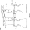
- FIG. 1B is a schematic view of a turbine section that may employ various embodiments disclosed herein.
- Turbine 100 includes a plurality of airfoils, including, for example, one or more blades 101 and vanes 102.
- the airfoils 101, 102 may be hollow bodies with internal cavities defining a number of channels or cavities, hereinafter airfoil cavities, formed therein and extending from an inner diameter 106 to an outer diameter 108, or vice-versa.
- the airfoil cavities may be separated by partitions within the airfoils 101, 102 that may extend either from the inner diameter 106 or the outer diameter 108 of the airfoil 101, 102.
- the partitions may extend for a portion of the length of the airfoil 101, 102, but may stop or end prior to forming a complete wall within the airfoil 101, 102.
- each of the airfoil cavities may be fluidly connected and form a fluid path within the respective airfoil 101, 102.
- the blades 101 and the vanes may include platforms 110 located proximal to the inner diameter or outer diameter thereof. Located below the platforms 110 may be airflow ports and/or bleed orifices that enable air to bleed from the internal cavities of the airfoils 101, 102. A root of the airfoil may connected to or be part of the platform 110.
- turbine airfoils can operate in high temperature environments that, in some circumstances, may exceed the melting point of the material of the airfoil.
- cooling air is passed through it from the compressor.
- the coolant travels through the airfoil cavities which are designed to promote convective heat transfer.
- the cooling air can then be discharged out the airfoil through cavity slots (e.g., exits).
- the air exiting the slots can form a film of cooler air along surfaces of the airfoil and thus shield the airfoil from incoming hot fluids (e.g., combustion gases).
- discharge cooling air flows can be provided to or on multiple surfaces of an airfoil by using stacked core subassemblies or bodies to form a core assembly during formation and/or manufacture of the airfoils.
- the core bodies, core subassemblies, and/or core assemblies can include refractory metal cores (RMCs).
- RMCs are a tool that makes a negative in the final airfoil body and the airfoil is produced from positive material.
- the cores and/or core bodies can be bent in singular concepts, shapes, geometries, etc. and in multi-core configurations, the cores and/or core bodies can be glued, pancaked, welded, brazed, mechanically joined, or otherwise joined to create a desired stack and/or airfoil cavity configuration.
- Stacks of core bodies as provided herein can be optimized for heat transfer and desired flow characteristics through and along an airfoil.
- the component e.g., an airfoil
- FIGS. 2A and 2B schematic illustrations of an airfoil ( FIG. 2A ) and a core assembly ( FIG. 2B ) are shown.
- FIG. 2A is a cross-sectional illustration of an airfoil 201 cast using the core assembly 212 shown in FIG. 2B.
- FIG. 2B is a perspective illustration of the core assembly 212 used to form the airfoil 201 of FIG. 2A .
- FIG. 2A illustrates a cross-sectional illustration of the airfoil 201 cast using the core assembly 212 illustrated in FIG. 2B .
- Airfoil 201 includes leading edge surface 214, trailing edge 216, pressure side surface 218, suction side surface 220, leading edge cavity 222, midchord cavity 224, trailing edge cavity 226, and cooling circuits 228a, 228b, and 228c.
- leading edge cavity 222 is formed by a leading edge ceramic core
- midchord cavity 224 is formed by a midchord ceramic core
- trailing edge cavity 226 is formed by a trailing edge ceramic core (see, e.g., FIG. 2B ).
- Each cavity 222, 224, 226 is bounded by a respective cavity wall 222a, 224a, 226a.
- One or more ribs 230 separate the cavities 222, 224, 226.
- Each cooling circuit 228a, 228b, 228c is formed by one or more core bodies, such as RMCs (see FIG. 2B ). As shown in FIG. 2A , cooling circuits 228a, 228b are positioned between a downstream cavity (e.g., 224, 226) and a side (e.g., pressure side surface 218) of airfoil 201.
- cooling circuit 228a fluidly connects leading edge cavity 222 along a downstream portion of cavity wall 222a and extends between midchord cavity 224 and pressure side surface 218. As such, cooling fluid flowing through leading edge cavity 222 exits the cavity 222 and flows through cooling circuit 228a to cool the pressure side surface 218 of airfoil 201.
- cooling circuit 228b joins with midchord cavity 224 along a downstream portion of cavity wall 224a and extends between trailing edge cavity 226 and pressure side surface 218. Cooling fluid exits midchord cavity 224 and flows through cooling circuit 228b to cool the pressure side surface 218 of airfoil 201 farther downstream of cooling circuit 228a. While FIG. 2A illustrates cooling circuits near the pressure side surface 218 of airfoil 201, cooling circuits can also be located between the cavities 222, 224, 226 and the suction side surface 220 of airfoil 201.
- FIG. 2B illustrates a perspective view of one embodiment of a core assembly 212 for forming an airfoil 201.
- Core assembly 212 includes leading edge ceramic core 232, midchord ceramic core 234, and trailing edge ceramic core 236.
- a first core body 238a is configured with the leading edge ceramic core 232
- a second core body 238b is configured with the midchord ceramic core 234, and
- a third core body 238c is configured with the trailing edge ceramic core 236.
- the ceramic cores 232, 234, 236 are used to form inner passages (e.g., cavities 222, 224, 226) for cooling fluid within the airfoil 201.
- the core bodies 238a, 238b, 238c are used to form cooling circuits (e.g., a network of cooling passages including cooling circuits 228a, 228b, 228c) within the airfoil 201.
- the cooling circuits 228a, 228b, 228c in the cast airfoil 201 will receive cooling fluid from the inner passage(s) 222, 224, 226 with which they are fluidly connected.
- the ceramic cores 232, 234, 236 and the core bodies 238a, 238b, 238c are in contact with one another.
- core bodies 238a, 238b, 238c are secured to the appropriate ceramic core 232, 234, 236 to maintain contact during a casting process.
- core assembly 212 can contain more than one midchord ceramic core 234 and associated downstream core body 238b.
- the core bodies of the present disclosure can be refractory metal cores.
- those of skill in the art will appreciate that other materials can be used to form the core bodies without departing from the scope of the present disclosure.
- Each of the core bodies 238a, 238b, 238c can include a plurality of openings 240, as shown.
- openings 240 form a plurality of air disturbance features, include pedestals or other features, which direct cooling fluid through a respective cooling circuit 228a, 228b, 228c.
- Openings 240 can be circular, oblong, racetrack-shaped, teardrop-shaped, or any other shape depending on the flow control needs of the specific cooling circuit 228a, 228b, 228c.
- additive manufacturing techniques can be used to form the structures and configurations of airfoils as provided herein.
- FIGS. 3A-4B schematic illustrations of core bodies and/or core subassemblies in accordance with non-limiting embodiments of the present disclosure are shown.
- FIGS. 3A-3E are top-down illustrations of core bodies and core subassemblies in various configurations.
- FIG. 4A is a top-down illustration of a core body in accordance with a non-limiting embodiment and
- FIG. 4B is an elevational illustration of the core body of FIG. 4A .
- the core bodies and subassemblies of FIGS. 3A-4B can be used with ceramic cores or other structures to form core assemblies and define a positive structure of the internal cavities (i.e., negative space) within an airfoil, such as described above.
- FIG. 3A is a first illustration of a core subassembly 338a that is constructed of two core bodies that are attached together.
- a first core body 342a and a second core body 344a are bonded together to form the core subassembly 338a, thus forming a core body stack.
- the attachment between the first core body 342a and the second core body 344a can be by any known mechanism including, but not limited to, gluing, brazing, pancaking, welding (e.g., friction, heat, etc.), laser operations, forging, pressing, mechanical fixing, and/or other joining processes or mechanisms.
- the core bodies and/or the core assembly can be additively manufactured.
- the core subassembly 338a includes a first portion 346a and a second portion 348a.
- the first portion 346a forms a trunk 350a that is defined as the portion or section of the core subassembly 338a where the first core body 342a and the second core body 344a are attached.
- the trunk 350a has a first end 352a and a second end 354a.
- the trunk 350a is a structure or portion of the core subassembly 338a that is configured to join with or attach to a ceramic core or other core structure used to form a cavity within an airfoil.
- the first end 352a of the trunk 350a is thus free to be engaged with or otherwise interact with a cavity core structure and the second end 354a is opposite therefrom.
- the second portion 348a is defined by one or more branches 356a that extend from the trunk 350a where the first core body 342a and the second core body 344a are not joined or attached (i.e., are separated from each other).
- the first core body 342a defines one branch 356a and the second core body 344a defines another branch 356a, each extending from the second end 354a of the trunk 350a.
- the trunk 350a will form a relatively wide cooling circuit that can extend from a cavity of the airfoil (e.g., as shown and described above).
- the cooling circuit can include multiple passages that extend to different locations and/or surfaces of the airfoil and thus provide cooling at multiple locations on the exterior of the airfoil.
- the multiple passages are based on the configuration of the branches 356a of the second portion 348a of the core subassembly 338a.
- FIG. 3B shows another configuration of a core subassembly 338b in accordance with an embodiment of the present disclosure.
- the core subassembly 338b is substantially similar to the core subassembly 338a of FIG. 3A and forms a similar cooling circuit in a manufactured airfoil.
- the core subassembly 338b is a unitary or single core body 342b.
- a trunk 350b is a portion of the single core body 342b and the branches 356b extend therefrom, with each branch 356b part of the single core body 342b.
- the trunk 350b is the portion of the core subassembly 338b that is configured to connect to or join with a ceramic core or other core structure that is used to form cavities of an airfoil.
- FIG. 3C shows another configuration of a core subassembly 338c in accordance with an embodiment of the present disclosure.
- a first core body 342c and multiple second core bodies 344c are connected on one side of the first core body 342c.
- a trunk 350c has multiple branches 356c extending therefrom. As shown, one of the branches 356c extends from a point between a first end 352c and a second end 354c of the trunk 350c.
- the two second core bodies 344c shown in FIG. 3C can be formed as a single, second core body without departing from the scope of the present disclosure.
- FIG. 3D shows another configuration of a core subassembly 338d in accordance with an embodiment of the present disclosure.
- the core subassembly 338d of FIG. 3D is a unitary, single core body 342d with a trunk 350d and multiple branches 356d extending from the trunk 350d. As shown in the embodiment of FIG. 3D , the branches 356d extend at different angles and form a "Y" configuration with the trunk 350d.
- FIG. 3E shows another configuration of a core subassembly 338e in accordance with an embodiment of the present disclosure.
- FIG. 3E illustrates that multiple second core bodies 344e can be attached to a first core body 342e.
- one second core body 344e is attached on a first side of the first core body 342e and multiple second core bodies 344e are attached on a second (and opposite) side of the first core body 342e.
- the trunk 350e is defined as any section of the core subassembly 338e where different core bodies 342e, 344e are attached.
- the branches 356e can extend from the trunk 350e from multiple locations along the length of the trunk 350e.
- FIGS. 4A-4B another configuration of a core subassembly 438 in accordance with an embodiment of the present disclosure is shown.
- FIG. 4A shows a top-down illustration of the core subassembly 438
- FIG. 4B shows an elevational illustration of the core subassembly 438.
- the core subassembly 438 includes a single core body 442 defining a trunk 450 and a plurality of branches 456a, 456b extending therefrom.
- a first set of branches 456a are configured to extend in a first direction relative to the trunk 450 and a second set of branches 456b are configured to extend in a second direction relative to the trunk 450.
- each branch 456a, 456b is angled from a second end 454 of the trunk 450 (as illustrated by the dashed line in FIGS. 4A-4B ).
- the two sets of branches 456a, 456b are shown alternating in configuration.
- any pattern or configuration of branches can be employed without departing from the scope of the present disclosure.
- a portion of the trunk e.g., where at least two core bodies are joined
- the trunk can extend the full length of the core assembly, such that a wider cooling circuit passageway can be formed for the length of the trunk.
- the trunk can bend, turn, or otherwise have a different geometry than a relatively straight line/body, as shown above.
- one or more of the core bodies used to form a core subassembly or core assembly of the present disclosure can include openings (e.g., openings 240 of FIG. 2B ) to form a plurality of pedestals or other features that direct cooling fluid through a respective cooling circuit.
- the openings can be circular, oblong, racetrack-shaped, teardrop-shaped, or any other shape.
- two joined core bodies can be configured to match or align openings of the two core bodies.
- one core body can include openings while the other core body does not include openings, thus forming a unique interior structure to the cooling circuits when the airfoil is formed from the core assembly including the two different core bodies.
- multiple of the core bodies can be configured with openings that do not align, or some openings that align and other that do not, thus enabling unique pedestal structures and/or configurations.
- FIGS. 5-7 schematic illustrations of airfoils formed from core assemblies and subassemblies as provided herein are shown.
- FIGS. 5-6 each show a trailing edge of respective airfoils and
- FIG. 7 shows an airfoil extending from a leading edge to a trailing edge.
- FIGS. 5-7 is a cross-sectional, top-down view of the interior structure of the respective airfoils.
- airfoil 501 includes a trailing edge cavity 526 that is fluidly connected to exterior surfaces of the airfoil 501 by cooling circuit 528.
- cooling circuit 528 has two exits with one exit configured near the trailing edge 516 but being open on a pressure side surface 518. The other of the exits of the cooling circuit 528 is formed in the trailing edge 516 of the airfoil 501.
- the airfoil 501 is manufactured using at least one core subassembly similar to that shown and described above.
- the configuration and geometry of the cooling circuit 528 of FIG. 5 could be formed using a core subassembly similar to that shown in either FIG. 3A or FIG. 3B .
- the trunk of the core subassembly would be connected to a ceramic core that forms the trailing edge cavity 526, and the branches of the core subassembly would extend toward the trailing edge.
- FIG. 6 shows an alternative configuration of a trailing edge 616 of an airfoil 601 in accordance with an embodiment of the present disclosure.
- the airfoil 601 includes a trailing edge cavity 626 with a cooling circuit 628 extending from the trailing edge cavity 626 toward the trailing edge 616.
- the cooling circuit 628 has two exits that open onto each of the pressure surface side 618 and the suction surface side 620.
- the cooling circuit 628 can be formed, for example, by a core subassembly similar to that shown in FIG. 3D .
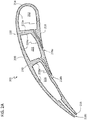
- the airfoil 701 extends from a leading edge 714 to a trailing edge 716. As shown, the airfoil 701 includes a leading edge cavity 722, two midchord cavities 724, and a trailing edge cavity 726.
- the trailing edge cavity 726 includes two separate cooling circuits 728c, with one exiting onto a pressure side surface 718 and one exiting at the trailing edge 716. Further, as shown in the embodiment of FIG.
- the airfoil 701 does not include any cooling circuits connected to the midchord cavities 724, although those of skill in the art will appreciate that cooling circuits could be formed therewith (e.g., fluidly exiting from the midchord cavities 724 to a suction side surface 720.
- the leading edge cavity 722 includes multiple cooling circuits 728a. As shown, a first cooling circuit 728a' can connect the leading edge cavity 722 to the pressure side surface 718 by a single passaged cooling circuit. Additionally, the leading edge cavity 722 is fluidly connected to the pressure side surface 718 by a second cooling circuit 728a" that is formed by a core subassembly in accordance with the present disclosure. As shown, the second cooling circuit 728a" has a larger section near the leading edge cavity 722 (e.g., formed by the trunk of the RMC) and two separate exits exiting onto the pressure surface side 718 (e.g., each formed by a branch of the core subassembly).
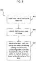
- the flow process 800 involves a casting process for the airfoil based on ceramic cores and core assemblies using RMCs.
- RMC ceramic cores and core assemblies
- alternative manufacturing techniques can be used to form an airfoil having internal structures and/or configurations as described herein.
- RMC ceramic cores and core assemblies
- the flow process 800 is not intended to be limiting, but rather is provided for illustrative purposes.
- an RMC having a trunk and branches formed thereon is formed.
- the formation of the RMC can be by additive manufacturing, with the trunk and branches integrally formed in a single piece or component.
- the formation of the RMC can involve attaching or joining multiple RMC bodies to form the RMC having a trunk at the portions where at least two RMC bodies are joined or attached and branches where an RMC body is not attached to another RMC body.
- the attachment or joining of the RMC bodies can be by any known means and can include welding, gluing, laser operations, mechanically fixing, etc.
- a branch (as described above) can be attached to another RMC body and the trunk can be a portion of the RMC body that is configured to interact with a cavity core structure, as shown and described above.
- the branches can be formed by bending a portion or portions of the RMC body (e.g., as shown in FIGS. 4A-4B ).
- the RMC can then be attached to a cavity core structure, as shown at block 804.
- the cavity core structure may be a ceramic core.
- the attachment between the RMC and the cavity core structure may be by any means, as will be appreciated by those of skill in the art.
- an airfoil can be formed from the RMC and cavity core structure.
- the formed airfoil includes cooling circuits fluidly connecting internal cavities to exterior surfaces of the airfoil at multiple locations based on the branches of the RMC. That is, the cavity core structure can form the internal cavities and the RMC (trunk and branches) can form the cooling circuits, as shown and described herein.
- FIG. 9 a schematic illustration of an airfoil 901 having features in accordance with a non-limiting embodiment of the present disclosure is shown.
- the airfoil 901 extends from a leading edge (not shown) to a trailing edge 916.
- the airfoil 901 includes a trailing edge cavity 926.
- the trailing edge cavity 926 includes two separate cooling circuits 960a, 960b that fluidly connect to the trailing edge cavity 926 at two separate locations 962a, 962b (e.g., a pressure side opening 962a and a suction side opening 962b).
- the two separate cooling circuits 960a, 960b fluidly connect at a junction 964 and exit at the trailing edge 916 at a trailing edge exit 966.
- each of the cooling circuits 960a, 960b includes a side exit (e.g., pressure side exit 968a or suction side exit 968b).
- a pressure side cooling circuit 960a on a pressure side of the airfoil 901 has a pressure side exit 968a that opens on or through a pressure side surface 918 of the airfoil 901.
- a suction side cooling circuit 960b on a suction side of the airfoil 901 has a suction side exit 968b that opens on or through a suction side surface 920 of the airfoil 901.
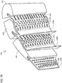
- FIGS. 10A-10B schematic illustrations of a core subassembly 1070 used to form the cooling circuits shown in FIG. 9 are shown.
- FIG. 10A is a cross-sectional view illustration of a first core body 1070a and a second core body 1070b that are separated, but can be joined to form the cooling circuit described above with respect to FIG. 9 .
- FIG. 10B is an isometric illustration of the first core body 1070a, with the second core body 1070b being a mirror of the first core body 1070a.
- the first and second core bodies 1070a, 1070b can be joined to form the core subassembly 1070.
- the core bodies 1070a, 1070b each have a respective trunk 1072a, 1072b that is configured to join with or attach to a ceramic core or other core structure used to form a cavity within an airfoil.
- One or more first branches 1074a, 1074b and one or more second branches 1076a, 1076b can extend from the respective trunks 1072a, 1072b (e.g., laterally or vertically on the refractory metal core body).
- the first branches 1074a, 1074b can form the portion of the cooling circuit within the airfoil that exits at a trailing edge of the airfoil (e.g., as shown in FIG. 9 ).
- the second branches 1076a, 1076b can form portions of a cooling circuit that exits on a pressure or suction side of the airfoil.
- the second branch 1076a of the first core body 1070a can be used to form a cooling circuit that exits an airfoil on the pressure side surface of the airfoil.
- the second branch 1076b of the second core body 1070b can be used to form a cooling circuit that exits the airfoil on the suction side surface of the airfoil.
- first joining surface 1078a can be defined on the first branch 1074a of the first core body 1070a and a second joining surface 1078b can be defined on the first branch 1074b of the second core body 1070b.
- the joining surfaces 1078a, 1078b can be configured to enable joining of the first core body 1070a to the second core body 1070b by means of glue, pancaking (e.g., press-fusion), welding, brazing, mechanical joining, or other joining mechanism or procedure to create a desired stack and thus form the core subassembly 1070. As shown in FIG.
- the first core body 1070a is illustrated in an isometric view, illustrating the nature of the first and second branches 1074a, 1076a.
- the second branches 1076a are bent or skewed relative to the first branches 1074a, and thus enable different exits for cooling cavities on one or more surfaces of an airfoil formed based on the core subassembly 1070.
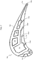
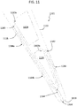
- FIG. 11 an airfoil 1101 is shown.
- the airfoil 1101 extends from a leading edge (not shown) to a trailing edge 1116.
- the airfoil 1101 includes a midchord cavity 1124 and a trailing edge cavity 1126.
- each of the cavities 1124, 1126 is fluidly connected to a respective cooling circuit 1180, 1182.
- the two cooling circuits 1180, 1182 fluidly connect at a junction 1164 and exit at a trailing edge 1116 at a trailing edge exit 1166 of the airfoil 1101.
- Each of the cooling circuits 1180, 1182 can be formed, in part, by separate core bodies or core subassemblies, as described above. However, as shown and similar to that described with respect to FIGS. 9-10B , the two core bodies can be joined toward a trailing edge to form the trailing edge exit 1166 where the junction 1164 is formed and the two cooling circuits 1180, 1182 merge. Further, as shown in the embodiment of FIG.
- each of the cooling circuits 1180, 1182 includes one or more side exits (e.g., pressure side exit 1184a, 1184b or suction side exit 1186).
- a pressure side cooling circuit 1180 on a pressure side of the airfoil 1101 has a first pressure side exit 1184a and a second pressure side exit 1184b that each open on or through a pressure side surface 1118 of the airfoil 1101.
- a suction side cooling circuit 1182 on a suction side of the airfoil 1101 has a suction side exit 1186 that opens on or through a suction side surface 1120 of the airfoil 1101. As shown in FIGS.
- two or more core bodies or core subassemblies can be configured to fluidly connect to one or more internal cavities of an airfoil, and then join proximate to an exit from the airfoil, thus forming cooling circuits as shown and described herein.
- cooling circuits as shown and described herein.
- core assemblies, core subassemblies, core bodies, and/or cooling circuits can be formed using embodiments of the present disclosure.
- embodiments described herein can provide improved high temperature applications for airfoil.
- Using core subassemblies as provided herein can be employed to optimize pressure side film cooling, while allowing for a more conventional serpentine cavity (e.g., midchord cavities) to be dedicated on the suction side of the airfoil.
- the double-stack core subassembly (or stack of core bodies) of some embodiments provided herein can be configured to provide superposition of slot film effectiveness on the pressure side of the airfoil and greatly benefit the trailing edge temperatures. Further, multiple core body and/or core subassembly insertions into the ceramic cores can be minimized. That is, core subassemblies and core bodies as provided herein can be joined to a ceramic core at a single location (e.g., single trunk) and still provide multiple exits (e.g., branches) at various locations on the exteriors surfaces of the airfoil.
- embodiments provided herein can provide cooling discharge on pressure side, suction side, trailing edge, top and/or bottom platform, and/or combinations thereof. That is, advantageously, cooling flow is enabled on multiple sides of a component from a single internal cavity of the component. Advantageously, such cooling can enable product life improvement which can decrease product life cycle costs.
- airfoils e.g., vanes and blades
- embodiments provided herein can be used in the manufacture of blade outer air seals, combustor panels, or other components that employ fluid cooling.
- airfoils e.g., vanes and blades
- combustor panels e.g., combustor panels
- fluid cooling e.g., fluid cooling
- primarily described with respect to conventional casting, additive manufacturing and machining methods can be used without departing from the scope of the present disclosure.
Landscapes
- Engineering & Computer Science (AREA)
- Mechanical Engineering (AREA)
- Chemical & Material Sciences (AREA)
- Combustion & Propulsion (AREA)
- General Engineering & Computer Science (AREA)
- Turbine Rotor Nozzle Sealing (AREA)
- Molds, Cores, And Manufacturing Methods Thereof (AREA)
Description
- The subject matter disclosed herein generally relates to gas turbine engine components and, more particularly, to core assemblies, core subassemblies, and core bodies for manufacturing components of gas turbine engines.
- Turbine engine components, such as turbine blades and vanes, are operated in high temperature environments. To avoid deterioration in the components resulting from their exposure to high temperatures, it is necessary to provide cooling circuits within the components. Turbine blades and vanes are subjected to high thermal loads on both the suction and pressure sides of their airfoil portions and at both the leading and trailing edges. The regions of the airfoils having the highest thermal load can differ depending on engine design and specific operating conditions.
- Refractory metal core technology offers the potential to provide higher specific cooling passages for turbine components such as blade and vane airfoils and seals. Refractory metal core technology allows cooling circuits to be placed just under the surface of the airfoil through which cooling air flows and is expelled into the gaspath. Improved cooling circuits within turbine components may be advantageous.
-
EP 1 524 046 A1 discloses a shaped refractory metal sheet having a plurality of features for forming a plurality of film cooling passages, which features are formed from refractory metal bent out of the sheet. -
WO 2014/039124 A1 discloses a core assembly for forming a cast component including a refractory metal core and a ceramic core element. - In accordance with an embodiment, core subassemblies for manufacturing components of gas turbine engines are provided. The core subassemblies include a first core body having a first trunk configured to attach to a first location of a cavity core structure, a first branch of the first core body extending from the first trunk and configured to form a first portion of a first cooling circuit in the component, the first branch having a first joining surface and a second core body having a second trunk configured to attach to a second location of a cavity core structure, a first branch of the second core body extending from the second trunk and configured to form a first portion of a second cooling circuit in the component, the first branch of the second core body having a second joining surface joined to the first joining surface to form a junction. The junction defines a merger of the first cooling circuit and the second cooling circuit proximate to an exit of the first and second cooling circuits from the component.
- In addition to one or more of the features described herein, or as an alternative, further embodiments of the core subassemblies may include that the first core body includes a second branch extending from the first trunk to define a second exit of the first cooling circuit.
- In addition to one or more of the features described herein, or as an alternative, further embodiments of the core subassemblies may include that the second exit is formed in one of a pressure side surface or a suction side surface of the component.
- In addition to one or more of the features described herein, or as an alternative, further embodiments of the core subassemblies may include that the second core body includes a second branch extending from the second trunk to define a second exit of the second cooling circuit.
- In addition to one or more of the features described herein, or as an alternative, further embodiments of the core subassemblies may include that the second exit of the first cooling circuit and the second exit of the second cooling circuit are on opposite side surfaces of the component.
- In addition to one or more of the features described herein, or as an alternative, further embodiments of the core subassemblies may include that at least one of the first core body and the second core body is a refractory metal core.
- In addition to one or more of the features described herein, or as an alternative, further embodiments of the core subassemblies may include that the first core body and the second core body are attached at the junction by at least one of welding, gluing, forging, pressing, laser operations, or mechanical attachment.
- In addition to one or more of the features described herein, or as an alternative, further embodiments of the core subassemblies may include that at least one of the first core body and the second core body includes a plurality of openings configured to form a plurality of air disturbance features in the component.
- In addition to one or more of the features described herein, or as an alternative, further embodiments of the core subassemblies may include that the first location is on a first internal cavity core structure and the second location is on a second internal cavity core structure that is different from the first internal cavity core structure.
- In addition to one or more of the features described herein, or as an alternative, further embodiments of the core subassemblies may include that the first location and the second location are different locations on a single internal cavity core structure.
- In addition to one or more of the features described herein, or as an alternative, further embodiments of the core subassemblies may include that the first location and the second location are different from each other.
- According to another embodiment, components for gas turbine engines are provided. The components include a cavity formed inside the component and defining a cooling flow path within the component, a first cooling circuit fluidly connecting the cavity to an exterior of the component, wherein the first cooling circuit comprises a first portion and a second portion wherein the first portion of the cooling circuit and the second portion of the cooling circuit are configured to define a first exit and a second exit at two different locations on the exterior of the component, and wherein the first portion and the second portion extend from a trunk portion of the first cooling circuit, and a second cooling circuit formed within the component and merging with the first cooling circuit proximate the first exit of the first cooling circuit.
- In addition to one or more of the features described herein, or as an alternative, further embodiments of the components may include that at least one of the trunk portion, the first portion of the cooling circuit, or the second portion of the cooling circuit includes a plurality of air disturbance features in the cooling circuit.
- In addition to one or more of the features described herein, or as an alternative, further embodiments of the components may include that the second cooling circuit is fluidly connected to the cavity at a location different from a location where the first cooling circuit fluidly connects to the cavity.
- In addition to one or more of the features described herein, or as an alternative, further embodiments of the components may include that the second cooling circuit is fluidly connected to a second cavity different from the cavity the first cooling circuit is fluidly connected to.
- In addition to one or more of the features described herein, or as an alternative, further embodiments of the components may include that the first exit is on an end of the component and the second exit of the first cooling circuit is on a pressure side surface or suction side surface of the component.
- In addition to one or more of the features described herein, or as an alternative, further embodiments of the components may include that the second cooling circuit has a second exit separate from the location of the merging with the first cooling circuit.
- According to another embodiment, methods of manufacturing components for gas turbine engines are provided. The methods include forming a core subassembly having a first core body with a trunk that attaches to a cavity core structure, a first branch extending from the trunk and configured to form a first portion of a first cooling circuit in the component, and a second branch extending from the trunk and configured to form a second portion of the first cooling circuit in the component, the first branch of the first core body having a first joining surface, attaching a second core body to the first core body at the first joining surface to form a junction, the second core body configured to define a second cooling circuit within the component, and attaching the first core body to a cavity core structure. The junction of the first core body and the second core body define a merging of the first and second cooling circuits proximate an end of the component.
- In addition to one or more of the features described herein, or as an alternative, further embodiments of the methods may include forming the component having an interior cavity based on the cavity core structure and cooling circuits defined by the first and second core bodies.
- In addition to one or more of the features described herein, or as an alternative, further embodiments of the methods may include attaching the second core body to the same cavity core structure as the first core body.
- In addition to one or more of the features described herein, or as an alternative, further embodiments of the methods may include attaching the second core body to a different cavity core structure than the cavity core structure the first core body is attached to.
- Technical effects of embodiments of the present disclosure include core assemblies and core bodies, such as refractory metal cores, for manufacturing components of gas turbine engines having a trunk and multiple branches extending therefrom. Further technical effects include components for gas turbine engines having a cavity and a branch portion of a cooling circuit extending therefrom with multiple branch portions of the cooling circuit extending from the trunk to define multiple, different exits on an exterior of the component. Further technical effects include cooling circuits of gas turbine engine components that can start at different locations within the component and merge proximate to an exit from the component and associated cores and core bodies to form such configurations.
- The foregoing features and elements may be combined in various combinations without exclusivity, unless expressly indicated otherwise. These features and elements as well as the operation thereof will become more apparent in light of the following description and the accompanying drawings. It should be understood, however, that the following description and drawings are intended to be illustrative and explanatory in nature and non-limiting.
- The subject matter is particularly pointed out and distinctly claimed at the conclusion of the specification. The foregoing and other features, and advantages of the present disclosure are apparent from the following detailed description, which is given by way of example only, taken in conjunction with the accompanying drawings in which:
-
FIG. 1A is a schematic cross-sectional illustration of a gas turbine engine that may employ various embodiments disclosed herein; -
FIG. 1B is a schematic illustration of a turbine that may employ various embodiments disclosed herein; -
FIG. 2A is a cross-sectional illustration of an airfoil cast using the core assembly shown inFIG. 2B ; -
FIG. 2B is a perspective illustration of a core assembly used to form the airfoil ofFIG. 2A ; -
FIG. 3A is a top-down schematic illustration of a core subassembly in accordance with a non-limiting embodiment of the present disclosure; -
FIG. 3B is a top-down schematic illustration of another core subassembly in accordance with a non-limiting embodiment of the present disclosure; -
FIG. 3C is a top-down schematic illustration of another core subassembly in accordance with a non-limiting embodiment of the present disclosure; -
FIG. 3D is a top-down schematic illustration of another core subassembly in accordance with a non-limiting embodiment of the present disclosure; -
FIG. 3E is a top-down schematic illustration of another core subassembly in accordance with a non-limiting embodiment of the present disclosure; -
FIG. 4A is a top-down schematic illustration of another core subassembly in accordance with a non-limiting embodiment of the present disclosure; -
FIG. 4B is a side elevation schematic illustration of the core subassembly ofFIG. 4A ; -
FIG. 5 is a cross-sectional illustration of a trailing edge of an airfoil formed using a core assembly in accordance with a non-limiting embodiment of the present disclosure; -
FIG. 6 is a cross-sectional illustration of a trailing edge of another airfoil formed using a core assembly in accordance with a non-limiting embodiment of the present disclosure; -
FIG. 7 is a cross-sectional illustration of an airfoil formed using a core assembly in accordance with a non-limiting embodiment of the present disclosure; -
FIG. 8 is a flow process for manufacturing a component of a gas turbine engine in accordance with a non-limiting embodiment of the present disclosure; and -
FIG. 9 is a cross-sectional illustration of an airfoil formed using a core assembly in accordance with a non-limiting embodiment of the present disclosure; -
FIG. 10A is a cross-sectional illustration of a subassembly that forms a portion of a core assembly, having a first core body and a second core body, in accordance with an embodiment of the present disclosure; -
FIG. 10B is an isometric illustration of the first core body ofFIG. 10A , the second core body being a mirror image thereof; and -
FIG. 11 is a cross-sectional illustration of an airfoil formed using a core assembly in accordance with a non-limiting embodiment of the present disclosure. - As shown and described herein, various features of the disclosure will be presented. Various embodiments may have the same or similar features and thus the same or similar features may be labeled with the same reference numeral, but preceded by a different first number indicating the figure to which the feature is shown. Thus, for example, element "a" that is shown in FIG. X may be labeled "Xa" and a similar feature in FIG. Z may be labeled "Za." Although similar reference numbers may be used in a generic sense, various embodiments will be described and various features may include changes, alterations, modifications, etc. as will be appreciated by those of skill in the art, whether explicitly described or otherwise would be appreciated by those of skill in the art.
-
FIG. 1A schematically illustrates agas turbine engine 20. The exemplarygas turbine engine 20 is a two-spool turbofan engine that generally incorporates afan section 22, acompressor section 24, acombustor section 26, and aturbine section 28. Alternative engines might include an augmenter section (not shown) among other systems for features. Thefan section 22 drives air along a bypass flow path B, while thecompressor section 24 drives air along a core flow path C for compression and communication into thecombustor section 26. Hot combustion gases generated in thecombustor section 26 are expanded through theturbine section 28. Although depicted as a turbofan gas turbine engine in the disclosed non-limiting embodiment, it should be understood that the concepts described herein are not limited to turbofan engines and these teachings could extend to other types of engines, including but not limited to, three-spool engine architectures. - The
gas turbine engine 20 generally includes alow speed spool 30 and ahigh speed spool 32 mounted for rotation about an engine centerline longitudinal axis A. Thelow speed spool 30 and thehigh speed spool 32 may be mounted relative to an enginestatic structure 33 viaseveral bearing systems 31. It should be understood that other bearingsystems 31 may alternatively or additionally be provided. - The
low speed spool 30 generally includes aninner shaft 34 that interconnects afan 36, alow pressure compressor 38 and alow pressure turbine 39. Theinner shaft 34 can be connected to thefan 36 through a gearedarchitecture 45 to drive thefan 36 at a lower speed than thelow speed spool 30. Thehigh speed spool 32 includes anouter shaft 35 that interconnects ahigh pressure compressor 37 and ahigh pressure turbine 40. In this embodiment, theinner shaft 34 and theouter shaft 35 are supported at various axial locations by bearingsystems 31 positioned within the enginestatic structure 33. - A
combustor 42 is arranged between thehigh pressure compressor 37 and thehigh pressure turbine 40. Amid-turbine frame 44 may be arranged generally between thehigh pressure turbine 40 and thelow pressure turbine 39. Themid-turbine frame 44 can support one ormore bearing systems 31 of theturbine section 28. Themid-turbine frame 44 may include one ormore airfoils 46 that extend within the core flow path C. - The
inner shaft 34 and theouter shaft 35 are concentric and rotate via the bearingsystems 31 about the engine centerline longitudinal axis A, which is co-linear with their longitudinal axes. The core airflow is compressed by thelow pressure compressor 38 and thehigh pressure compressor 37, is mixed with fuel and burned in thecombustor 42, and is then expanded over thehigh pressure turbine 40 and thelow pressure turbine 39. Thehigh pressure turbine 40 and thelow pressure turbine 39 rotationally drive the respectivehigh speed spool 32 and thelow speed spool 30 in response to the expansion. - The pressure ratio of the
low pressure turbine 39 can be pressure measured prior to the inlet of thelow pressure turbine 39 as related to the pressure at the outlet of thelow pressure turbine 39 and prior to an exhaust nozzle of thegas turbine engine 20. In one non-limiting embodiment, the bypass ratio of thegas turbine engine 20 is greater than about ten (10:1), the fan diameter is significantly larger than that of thelow pressure compressor 38, and thelow pressure turbine 39 has a pressure ratio that is greater than about five (5:1). It should be understood, however, that the above parameters are only examples of one embodiment of a geared architecture engine and that the present disclosure is applicable to other gas turbine engines, including direct drive turbofans. - In this embodiment of the example
gas turbine engine 20, a significant amount of thrust is provided by the bypass flow path B due to the high bypass ratio. Thefan section 22 of thegas turbine engine 20 is designed for a particular flight condition-typically cruise at about 0.8 Mach and about 35,000 feet. This flight condition, with thegas turbine engine 20 at its best fuel consumption, is also known as bucket cruise Thrust Specific Fuel Consumption (TSFC). TSFC is an industry standard parameter of fuel consumption per unit of thrust. - Each of the
compressor section 24 and theturbine section 28 may include alternating rows of rotor assemblies and vane assemblies (shown schematically) that carry airfoils that extend into the core flow path C. For example, the rotor assemblies can carry a plurality ofrotating blades 25, while each vane assembly can carry a plurality ofvanes 27 that extend into the core flow path C. Theblades 25 of the rotor assemblies extract energy (in the form of pressure) from the core airflow that is communicated through thegas turbine engine 20 along the core flow path C. Thevanes 27 of the vane assemblies direct the core airflow to theblades 25 to either add or extract energy. - Various components of a
gas turbine engine 20, including but not limited to the airfoils of theblades 25 and thevanes 27 of thecompressor section 24 and theturbine section 28, may be subjected to repetitive thermal cycling under widely ranging temperatures and pressures. The hardware of theturbine section 28 is particularly subjected to relatively extreme operating conditions. Therefore, some components may require internal cooling circuits for cooling the parts during engine operation. Example cooling circuits that include features such as airflow bleed ports are discussed below. -
FIG. 1B is a schematic view of a turbine section that may employ various embodiments disclosed herein.Turbine 100 includes a plurality of airfoils, including, for example, one ormore blades 101 andvanes 102. Theairfoils inner diameter 106 to anouter diameter 108, or vice-versa. The airfoil cavities may be separated by partitions within theairfoils inner diameter 106 or theouter diameter 108 of theairfoil airfoil airfoil respective airfoil blades 101 and the vanes may includeplatforms 110 located proximal to the inner diameter or outer diameter thereof. Located below theplatforms 110 may be airflow ports and/or bleed orifices that enable air to bleed from the internal cavities of theairfoils platform 110. - Although an aero or aircraft engine application is shown and described above, those of skill in the art will appreciate that airfoil configurations as described herein may be applied to industrial applications and/or industrial gas turbine engines, land based or otherwise.
- As noted, turbine airfoils can operate in high temperature environments that, in some circumstances, may exceed the melting point of the material of the airfoil. In order to cool the airfoil, cooling air is passed through it from the compressor. The coolant travels through the airfoil cavities which are designed to promote convective heat transfer. The cooling air can then be discharged out the airfoil through cavity slots (e.g., exits). The air exiting the slots can form a film of cooler air along surfaces of the airfoil and thus shield the airfoil from incoming hot fluids (e.g., combustion gases).
- In accordance with various embodiments of the present disclosure, discharge cooling air flows can be provided to or on multiple surfaces of an airfoil by using stacked core subassemblies or bodies to form a core assembly during formation and/or manufacture of the airfoils. In some embodiments the core bodies, core subassemblies, and/or core assemblies can include refractory metal cores (RMCs). RMCs are a tool that makes a negative in the final airfoil body and the airfoil is produced from positive material. As provided herein, the cores and/or core bodies can be bent in singular concepts, shapes, geometries, etc. and in multi-core configurations, the cores and/or core bodies can be glued, pancaked, welded, brazed, mechanically joined, or otherwise joined to create a desired stack and/or airfoil cavity configuration.
- Stacks of core bodies as provided herein can be optimized for heat transfer and desired flow characteristics through and along an airfoil. The component (e.g., an airfoil), in some embodiments, can be additive manufactured with the desired internal cavity and/or flow path geometries to allow discharge on more than one surface and/or at multiple locations on a single surface of the airfoil. Accordingly, advantageously, discharge of cooling air can be provided onto multiple surfaces of an airfoil thus improving convective and conductive heat transfer by utilizing a single cavity and reducing the number and complexity of multiple cores, resulting in efficient film cooling.
- Turning now to
FIGS. 2A and2B , schematic illustrations of an airfoil (FIG. 2A ) and a core assembly (FIG. 2B ) are shown.FIG. 2A is a cross-sectional illustration of anairfoil 201 cast using thecore assembly 212 shown inFIG. 2B. FIG. 2B is a perspective illustration of thecore assembly 212 used to form theairfoil 201 ofFIG. 2A . -
FIG. 2A illustrates a cross-sectional illustration of theairfoil 201 cast using thecore assembly 212 illustrated inFIG. 2B .Airfoil 201 includes leadingedge surface 214, trailingedge 216,pressure side surface 218,suction side surface 220, leadingedge cavity 222,midchord cavity 224, trailingedge cavity 226, andcooling circuits edge cavity 222 is formed by a leading edge ceramic core,midchord cavity 224 is formed by a midchord ceramic core, and trailingedge cavity 226 is formed by a trailing edge ceramic core (see, e.g.,FIG. 2B ). Eachcavity respective cavity wall more ribs 230 separate thecavities cooling circuit FIG. 2B ). As shown inFIG. 2A , coolingcircuits airfoil 201. - As shown, cooling
circuit 228a fluidly connects leadingedge cavity 222 along a downstream portion ofcavity wall 222a and extends betweenmidchord cavity 224 andpressure side surface 218. As such, cooling fluid flowing through leadingedge cavity 222 exits thecavity 222 and flows throughcooling circuit 228a to cool thepressure side surface 218 ofairfoil 201. Similarly, coolingcircuit 228b joins withmidchord cavity 224 along a downstream portion ofcavity wall 224a and extends between trailingedge cavity 226 andpressure side surface 218. Cooling fluid exitsmidchord cavity 224 and flows throughcooling circuit 228b to cool thepressure side surface 218 ofairfoil 201 farther downstream ofcooling circuit 228a. WhileFIG. 2A illustrates cooling circuits near thepressure side surface 218 ofairfoil 201, cooling circuits can also be located between thecavities suction side surface 220 ofairfoil 201. -
FIG. 2B illustrates a perspective view of one embodiment of acore assembly 212 for forming anairfoil 201.Core assembly 212 includes leading edgeceramic core 232, midchordceramic core 234, and trailing edgeceramic core 236. Afirst core body 238a is configured with the leading edgeceramic core 232, asecond core body 238b is configured with the midchordceramic core 234, and a thirdcore body 238c is configured with the trailing edgeceramic core 236. Theceramic cores cavities airfoil 201. Thecore bodies cooling circuits airfoil 201. Thecooling circuits cast airfoil 201 will receive cooling fluid from the inner passage(s) 222, 224, 226 with which they are fluidly connected. In order for thecooling circuits cast airfoil 201 to receive cooling fluid from theinner passages ceramic cores core bodies core bodies ceramic core core assembly 212 can contain more than one midchordceramic core 234 and associated downstreamcore body 238b. - In some non-limiting embodiments, the core bodies of the present disclosure, described above and below, can be refractory metal cores. However, those of skill in the art will appreciate that other materials can be used to form the core bodies without departing from the scope of the present disclosure.
- Each of the
core bodies openings 240, as shown. Once cast,openings 240 form a plurality of air disturbance features, include pedestals or other features, which direct cooling fluid through arespective cooling circuit Openings 240 can be circular, oblong, racetrack-shaped, teardrop-shaped, or any other shape depending on the flow control needs of thespecific cooling circuit - Turning now to
FIGS. 3A-4B , schematic illustrations of core bodies and/or core subassemblies in accordance with non-limiting embodiments of the present disclosure are shown.FIGS. 3A-3E are top-down illustrations of core bodies and core subassemblies in various configurations.FIG. 4A is a top-down illustration of a core body in accordance with a non-limiting embodiment andFIG. 4B is an elevational illustration of the core body ofFIG. 4A . The core bodies and subassemblies ofFIGS. 3A-4B can be used with ceramic cores or other structures to form core assemblies and define a positive structure of the internal cavities (i.e., negative space) within an airfoil, such as described above. -
FIG. 3A is a first illustration of acore subassembly 338a that is constructed of two core bodies that are attached together. For example, as shown, afirst core body 342a and asecond core body 344a are bonded together to form thecore subassembly 338a, thus forming a core body stack. The attachment between thefirst core body 342a and thesecond core body 344a can be by any known mechanism including, but not limited to, gluing, brazing, pancaking, welding (e.g., friction, heat, etc.), laser operations, forging, pressing, mechanical fixing, and/or other joining processes or mechanisms. Further, in some embodiments, the core bodies and/or the core assembly can be additively manufactured. - The
core subassembly 338a includes afirst portion 346a and asecond portion 348a. In the embodiment ofFIG. 3A , thefirst portion 346a forms atrunk 350a that is defined as the portion or section of thecore subassembly 338a where thefirst core body 342a and thesecond core body 344a are attached. Thetrunk 350a has afirst end 352a and asecond end 354a. Thetrunk 350a is a structure or portion of thecore subassembly 338a that is configured to join with or attach to a ceramic core or other core structure used to form a cavity within an airfoil. Thefirst end 352a of thetrunk 350a is thus free to be engaged with or otherwise interact with a cavity core structure and thesecond end 354a is opposite therefrom. - The
second portion 348a is defined by one ormore branches 356a that extend from thetrunk 350a where thefirst core body 342a and thesecond core body 344a are not joined or attached (i.e., are separated from each other). In this embodiment, thefirst core body 342a defines onebranch 356a and thesecond core body 344a defines anotherbranch 356a, each extending from thesecond end 354a of thetrunk 350a. - During manufacture of an airfoil based on, in part, the
core subassembly 338a, thetrunk 350a will form a relatively wide cooling circuit that can extend from a cavity of the airfoil (e.g., as shown and described above). However, due to the configuration and structure of thecore subassembly 338a, the cooling circuit can include multiple passages that extend to different locations and/or surfaces of the airfoil and thus provide cooling at multiple locations on the exterior of the airfoil. The multiple passages are based on the configuration of thebranches 356a of thesecond portion 348a of thecore subassembly 338a. -
FIG. 3B shows another configuration of a core subassembly 338b in accordance with an embodiment of the present disclosure. The core subassembly 338b is substantially similar to thecore subassembly 338a ofFIG. 3A and forms a similar cooling circuit in a manufactured airfoil. However, as shown inFIG. 3B , the core subassembly 338b is a unitary orsingle core body 342b. In this case, atrunk 350b is a portion of thesingle core body 342b and thebranches 356b extend therefrom, with eachbranch 356b part of thesingle core body 342b. Thetrunk 350b is the portion of the core subassembly 338b that is configured to connect to or join with a ceramic core or other core structure that is used to form cavities of an airfoil. -
FIG. 3C shows another configuration of a core subassembly 338c in accordance with an embodiment of the present disclosure. In this embodiment, afirst core body 342c and multiplesecond core bodies 344c are connected on one side of thefirst core body 342c. In this configuration, atrunk 350c hasmultiple branches 356c extending therefrom. As shown, one of thebranches 356c extends from a point between afirst end 352c and asecond end 354c of thetrunk 350c. In an alternative configuration, the twosecond core bodies 344c shown inFIG. 3C can be formed as a single, second core body without departing from the scope of the present disclosure. -
FIG. 3D shows another configuration of acore subassembly 338d in accordance with an embodiment of the present disclosure. Thecore subassembly 338d ofFIG. 3D is a unitary,single core body 342d with atrunk 350d andmultiple branches 356d extending from thetrunk 350d. As shown in the embodiment ofFIG. 3D , thebranches 356d extend at different angles and form a "Y" configuration with thetrunk 350d. -
FIG. 3E shows another configuration of a core subassembly 338e in accordance with an embodiment of the present disclosure.FIG. 3E illustrates that multiplesecond core bodies 344e can be attached to afirst core body 342e. As shown, onesecond core body 344e is attached on a first side of thefirst core body 342e and multiplesecond core bodies 344e are attached on a second (and opposite) side of thefirst core body 342e. Thetrunk 350e is defined as any section of the core subassembly 338e wheredifferent core bodies branches 356e can extend from thetrunk 350e from multiple locations along the length of thetrunk 350e. - Turning now to
FIGS. 4A-4B , another configuration of acore subassembly 438 in accordance with an embodiment of the present disclosure is shown.FIG. 4A shows a top-down illustration of thecore subassembly 438 andFIG. 4B shows an elevational illustration of thecore subassembly 438. As shown, thecore subassembly 438 includes asingle core body 442 defining atrunk 450 and a plurality ofbranches branches 456a are configured to extend in a first direction relative to thetrunk 450 and a second set ofbranches 456b are configured to extend in a second direction relative to thetrunk 450. As shown, eachbranch second end 454 of the trunk 450 (as illustrated by the dashed line inFIGS. 4A-4B ). In the embodiment ofFIGS. 4A-4B , the two sets ofbranches - Those of skill in the art will appreciate that various alternative configurations and/or geometries are enabled by the present disclosure. Further, several of the above described embodiments can be combined and/or altered to form a desired cooling circuit within an airfoil. In some embodiments, a portion of the trunk (e.g., where at least two core bodies are joined) can extend the full length of the core assembly, such that a wider cooling circuit passageway can be formed for the length of the trunk. Additionally, in some configurations, the trunk can bend, turn, or otherwise have a different geometry than a relatively straight line/body, as shown above.
- Further, in some embodiments, one or more of the core bodies used to form a core subassembly or core assembly of the present disclosure can include openings (e.g.,
openings 240 ofFIG. 2B ) to form a plurality of pedestals or other features that direct cooling fluid through a respective cooling circuit. The openings can be circular, oblong, racetrack-shaped, teardrop-shaped, or any other shape. Further, in some embodiments, two joined core bodies can be configured to match or align openings of the two core bodies. Moreover, in some embodiments, one core body can include openings while the other core body does not include openings, thus forming a unique interior structure to the cooling circuits when the airfoil is formed from the core assembly including the two different core bodies. Still further, multiple of the core bodies can be configured with openings that do not align, or some openings that align and other that do not, thus enabling unique pedestal structures and/or configurations. - Turning now to
FIGS. 5-7 , schematic illustrations of airfoils formed from core assemblies and subassemblies as provided herein are shown.FIGS. 5-6 each show a trailing edge of respective airfoils andFIG. 7 shows an airfoil extending from a leading edge to a trailing edge. Each ofFIGS. 5-7 is a cross-sectional, top-down view of the interior structure of the respective airfoils. - With reference to
FIG. 5 ,airfoil 501 includes a trailingedge cavity 526 that is fluidly connected to exterior surfaces of theairfoil 501 by coolingcircuit 528. As shown, coolingcircuit 528 has two exits with one exit configured near the trailingedge 516 but being open on apressure side surface 518. The other of the exits of thecooling circuit 528 is formed in the trailingedge 516 of theairfoil 501. Theairfoil 501 is manufactured using at least one core subassembly similar to that shown and described above. For example, the configuration and geometry of thecooling circuit 528 ofFIG. 5 could be formed using a core subassembly similar to that shown in eitherFIG. 3A or FIG. 3B . As shown, the trunk of the core subassembly would be connected to a ceramic core that forms the trailingedge cavity 526, and the branches of the core subassembly would extend toward the trailing edge. -
FIG. 6 shows an alternative configuration of a trailingedge 616 of anairfoil 601 in accordance with an embodiment of the present disclosure. Theairfoil 601 includes a trailingedge cavity 626 with acooling circuit 628 extending from the trailingedge cavity 626 toward the trailingedge 616. However, in this embodiment, as shown, thecooling circuit 628 has two exits that open onto each of thepressure surface side 618 and thesuction surface side 620. Thecooling circuit 628 can be formed, for example, by a core subassembly similar to that shown inFIG. 3D . - Turning now to
FIG. 7 , anairfoil 701 is shown. Theairfoil 701 extends from aleading edge 714 to a trailingedge 716. As shown, theairfoil 701 includes aleading edge cavity 722, twomidchord cavities 724, and a trailingedge cavity 726. The trailingedge cavity 726 includes twoseparate cooling circuits 728c, with one exiting onto apressure side surface 718 and one exiting at the trailingedge 716. Further, as shown in the embodiment ofFIG. 7 , theairfoil 701 does not include any cooling circuits connected to themidchord cavities 724, although those of skill in the art will appreciate that cooling circuits could be formed therewith (e.g., fluidly exiting from themidchord cavities 724 to asuction side surface 720. - The
leading edge cavity 722 includesmultiple cooling circuits 728a. As shown, afirst cooling circuit 728a' can connect theleading edge cavity 722 to thepressure side surface 718 by a single passaged cooling circuit. Additionally, theleading edge cavity 722 is fluidly connected to thepressure side surface 718 by asecond cooling circuit 728a" that is formed by a core subassembly in accordance with the present disclosure. As shown, thesecond cooling circuit 728a" has a larger section near the leading edge cavity 722 (e.g., formed by the trunk of the RMC) and two separate exits exiting onto the pressure surface side 718 (e.g., each formed by a branch of the core subassembly). - Turning now to
FIG. 8 , a flow process for forming or manufacturing an airfoil having cooling circuits as shown and described above is shown. Theflow process 800 involves a casting process for the airfoil based on ceramic cores and core assemblies using RMCs. However, alternative manufacturing techniques can be used to form an airfoil having internal structures and/or configurations as described herein. For example, although discussed with respect to RMC, this is merely for explanatory purposes and other materials or types of subassemblies can be employed without departing from the scope of the present disclosure. Thus, theflow process 800 is not intended to be limiting, but rather is provided for illustrative purposes. - At
block 802, an RMC having a trunk and branches formed thereon is formed. In some configurations, the formation of the RMC can be by additive manufacturing, with the trunk and branches integrally formed in a single piece or component. In other embodiments, the formation of the RMC can involve attaching or joining multiple RMC bodies to form the RMC having a trunk at the portions where at least two RMC bodies are joined or attached and branches where an RMC body is not attached to another RMC body. The attachment or joining of the RMC bodies can be by any known means and can include welding, gluing, laser operations, mechanically fixing, etc. In some configurations, a branch (as described above) can be attached to another RMC body and the trunk can be a portion of the RMC body that is configured to interact with a cavity core structure, as shown and described above. In some embodiments, the branches can be formed by bending a portion or portions of the RMC body (e.g., as shown inFIGS. 4A-4B ). - The RMC can then be attached to a cavity core structure, as shown at
block 804. In some embodiments, the cavity core structure may be a ceramic core. The attachment between the RMC and the cavity core structure may be by any means, as will be appreciated by those of skill in the art. - At
block 806, an airfoil can be formed from the RMC and cavity core structure. The formed airfoil includes cooling circuits fluidly connecting internal cavities to exterior surfaces of the airfoil at multiple locations based on the branches of the RMC. That is, the cavity core structure can form the internal cavities and the RMC (trunk and branches) can form the cooling circuits, as shown and described herein. - Turning now to
FIG. 9 , a schematic illustration of anairfoil 901 having features in accordance with a non-limiting embodiment of the present disclosure is shown. Theairfoil 901 extends from a leading edge (not shown) to a trailingedge 916. As shown, theairfoil 901 includes a trailingedge cavity 926. The trailingedge cavity 926 includes twoseparate cooling circuits edge cavity 926 at twoseparate locations pressure side opening 962a and asuction side opening 962b). As shown, the twoseparate cooling circuits junction 964 and exit at the trailingedge 916 at a trailingedge exit 966. - Further, as shown in the embodiment of
FIG. 9 , each of thecooling circuits pressure side exit 968a orsuction side exit 968b). For example, in this embodiment, as shown, a pressureside cooling circuit 960a on a pressure side of theairfoil 901 has apressure side exit 968a that opens on or through apressure side surface 918 of theairfoil 901. Similarly, a suctionside cooling circuit 960b on a suction side of theairfoil 901 has asuction side exit 968b that opens on or through asuction side surface 920 of theairfoil 901. - The separate and then joined
cooling circuits airfoil 901 through use of core assemblies, core subassemblies, and/or core bodies similar to that shown and described above. For example, turning now toFIGS. 10A-10B , schematic illustrations of acore subassembly 1070 used to form the cooling circuits shown inFIG. 9 are shown.FIG. 10A is a cross-sectional view illustration of afirst core body 1070a and asecond core body 1070b that are separated, but can be joined to form the cooling circuit described above with respect toFIG. 9 .FIG. 10B is an isometric illustration of thefirst core body 1070a, with thesecond core body 1070b being a mirror of thefirst core body 1070a. The first andsecond core bodies core subassembly 1070. - As shown in
FIGS. 10A-10B , thecore bodies respective trunk first branches second branches respective trunks first branches FIG. 9 ). Thesecond branches second branch 1076a of thefirst core body 1070a can be used to form a cooling circuit that exits an airfoil on the pressure side surface of the airfoil. Similarly, for example, thesecond branch 1076b of thesecond core body 1070b can be used to form a cooling circuit that exits the airfoil on the suction side surface of the airfoil. - To form the
core subassembly 1070, the twocore bodies surface 1078a can be defined on thefirst branch 1074a of thefirst core body 1070a and a second joiningsurface 1078b can be defined on thefirst branch 1074b of thesecond core body 1070b. The joiningsurfaces first core body 1070a to thesecond core body 1070b by means of glue, pancaking (e.g., press-fusion), welding, brazing, mechanical joining, or other joining mechanism or procedure to create a desired stack and thus form thecore subassembly 1070.
As shown inFIG. 10B , thefirst core body 1070a is illustrated in an isometric view, illustrating the nature of the first andsecond branches second branches 1076a are bent or skewed relative to thefirst branches 1074a, and thus enable different exits for cooling cavities on one or more surfaces of an airfoil formed based on thecore subassembly 1070.
Turning now toFIG. 11 , anairfoil 1101 is shown. Theairfoil 1101 extends from a leading edge (not shown) to atrailing edge 1116. As shown, theairfoil 1101 includes amidchord cavity 1124 and a trailingedge cavity 1126. In this embodiment, each of thecavities respective cooling circuit cooling circuits junction 1164 and exit at atrailing edge 1116 at a trailingedge exit 1166 of theairfoil 1101. Each of thecooling circuits FIGS. 9-10B , the two core bodies can be joined toward a trailing edge to form the trailingedge exit 1166 where thejunction 1164 is formed and the twocooling circuits
Further, as shown in the embodiment ofFIG. 11 , each of thecooling circuits pressure side exit side cooling circuit 1180 on a pressure side of theairfoil 1101 has a firstpressure side exit 1184a and a secondpressure side exit 1184b that each open on or through apressure side surface 1118 of theairfoil 1101. A suctionside cooling circuit 1182 on a suction side of theairfoil 1101 has asuction side exit 1186 that opens on or through asuction side surface 1120 of theairfoil 1101.
As shown inFIGS. 9-11 , two or more core bodies or core subassemblies can be configured to fluidly connect to one or more internal cavities of an airfoil, and then join proximate to an exit from the airfoil, thus forming cooling circuits as shown and described herein. Although certain geometries are shown and described herein, those of skill in the art will appreciate that various other geometries of core assemblies, core subassemblies, core bodies, and/or cooling circuits can be formed using embodiments of the present disclosure.
Advantageously, embodiments described herein can provide improved high temperature applications for airfoil. Using core subassemblies as provided herein can be employed to optimize pressure side film cooling, while allowing for a more conventional serpentine cavity (e.g., midchord cavities) to be dedicated on the suction side of the airfoil. - The double-stack core subassembly (or stack of core bodies) of some embodiments provided herein can be configured to provide superposition of slot film effectiveness on the pressure side of the airfoil and greatly benefit the trailing edge temperatures. Further, multiple core body and/or core subassembly insertions into the ceramic cores can be minimized. That is, core subassemblies and core bodies as provided herein can be joined to a ceramic core at a single location (e.g., single trunk) and still provide multiple exits (e.g., branches) at various locations on the exteriors surfaces of the airfoil.
- Further, advantageously, embodiments provided herein can provide cooling discharge on pressure side, suction side, trailing edge, top and/or bottom platform, and/or combinations thereof. That is, advantageously, cooling flow is enabled on multiple sides of a component from a single internal cavity of the component. Advantageously, such cooling can enable product life improvement which can decrease product life cycle costs.
- The use of the terms "a", "an", "the", and similar references in the context of description (especially in the context of the following claims) are to be construed to cover both the singular and the plural, unless otherwise indicated herein or specificaiiy contradicted by context. The modifier "about" used in connection with a quantity is inclusive of the stated value and has the meaning dictated by the context (e.g., it includes the degree of error associated with measurement of the particular quantity). All ranges disclosed herein are inclusive of the endpoints, and the endpoints are independently combinable with each other. It should be appreciated that relative positional terms such as "forward", "aft", "upper", "lower", "above", "below", and the like are with reference to normal operational attitude and should not be considered otherwise limiting.
- While the present disclosure has been described in detail in connection with only a limited number of embodiments, it should be readily understood that the present disclosure is not limited to such disclosed embodiments. Rather, the present disclosure can be modified to incorporate any number of variations, alterations, substitutions, combinations, subcombinations, or equivalent arrangements not heretofore described, but which are commensurate with the scope of the present disclosure. Additionally, while various embodiments of the present disclosure have been described, it is to be understood that aspects of the present disclosure may include only some of the described embodiments.
- For example, although shown and described with respect to airfoils (e.g., vanes and blades) embodiments provided herein can be used in the manufacture of blade outer air seals, combustor panels, or other components that employ fluid cooling. Moreover, although primarily described with respect to conventional casting, additive manufacturing and machining methods can be used without departing from the scope of the present disclosure.
- Accordingly, the present disclosure is not to be seen as limited by the foregoing description, but is only limited by the scope of the appended claims.
Claims (15)
- A core subassembly (1070) for manufacturing a component of a gas turbine engine (20), the core assembly comprising:a first core body (1070a) having a first trunk (1072a) configured to attach to a first location of a cavity core structure, a first branch (1074a) of the first core body extending from the first trunk and configured to form a first portion of a first cooling circuit (1180) in the component; anda second core body (1070b) having a second trunk (1072b) configured to attach to a second location of a cavity core structure, a first branch (1074b) of the second core body extending from the second trunk and configured to form a first portion of a second cooling circuit (1182) in the component;characterised in that:the first branch has a first joining surface (1078a) and the first branch of the second core body has a second joining surface (1078b) joined to the first joining surface to form a junction (1164),wherein the junction defines a merger of the first cooling circuit and the second cooling circuit proximate to an exit (1166) of the first and second cooling circuits from the component.
- The core subassembly (1070) of claim 1, wherein the first core body (1070a) includes a second branch (1076a) extending from the first trunk (1072a) to define a second exit (1184a) of the first cooling circuit (1180).
- The core subassembly (1070) of claim 2, wherein the second exit (1184a) is formed in one of a pressure side surface (1118) or a suction side surface (1120) of the component.
- The core subassembly (1070) of any of claims 2-3, wherein the second core body (1070b) includes a second branch (1076b) extending from the second trunk (1072b) to define a second exit (1186) of the second cooling circuit (1182).
- The core subassembly (1070) of claim 4, wherein the second exit (1184a) of the first cooling circuit (1180) and the second exit (1186) of the second cooling circuit (1182) are on opposite side surfaces of the component.
- The core subassembly (1070) of any preceding claim, wherein at least one of the first core body (1070a) and the second core body (1070b) is a refractory metal core.
- The core subassembly (1070) of any preceding claim, wherein the first core body (1070a) and the second core body (1070b) are attached at the junction (1164) by at least one of welding, gluing, forging, pressing, laser operations, or mechanical attachment.
- The core subassembly (1070) of any preceding claim, wherein at least one of the first core body (1070a) and the second core body (1070b) includes a plurality of openings (240) configured to form a plurality of air disturbance features in the component.
- The core subassembly (1070) of any preceding claim, wherein the first location is on a first internal cavity core structure and the second location is on a second internal cavity core structure that is different from the first internal cavity core structure.
- The core subassembly (1070) of any preceding claim, wherein the first location and the second location are different locations on a single internal cavity core structure.
- The core subassembly (1070) of any preceding claim, wherein the first location and the second location are different from each other.
- A component for a gas turbine engine (20) manufactured using the core subassembly (1070) of any of the preceding claims, the component comprising:a cavity (1124) formed inside the component and defining a cooling flow path within the component;a first cooling circuit (1180) fluidly connecting the cavity to an exterior of the component, wherein the first cooling circuit comprises a first portion and a second portion wherein the first portion of the cooling circuit and the second portion of the cooling circuit are configured to define a first exit (1166) and a second exit (1184a) at two different locations on the exterior of the component, and wherein the first portion and the second portion extend from a trunk portion of the first cooling circuit; anda second cooling circuit (1182) formed within the component and merging with the first cooling circuit proximate the first exit of the first cooling circuit.
- The component of claim 12, wherein at least one of the trunk portion, the first portion of the cooling circuit, or the second portion of the cooling circuit includes a plurality of air disturbance features in the cooling circuit.
- The component of any of claims 12-13, wherein the second cooling circuit (1182) is fluidly connected to the cavity (1124) at a location different from a location where the first cooling circuit (1180) fluidly connects to the cavity or wherein the second cooling circuit is fluidly connected to a second cavity (1126) different from the cavity the first cooling circuit is fluidly connected to or wherein the first exit (1166) is on an end of the component and the second exit (1184a) of the first cooling circuit is on a pressure side surface (1118) or suction side surface (1120) of the component.
- A method of forming a core for a component of a gas turbine engine (20), the method comprising:forming a core subassembly (1070) having a first core body (1070a) with a trunk (1072a) that attaches to a cavity core structure, a first branch (1074a) extending from the trunk and configured to form a first portion of a first cooling circuit (1180) in the component, and a second branch (1076a) extending from the trunk and configured to form a second portion of the first cooling circuit in the component,characterised by:the first branch of the first core body having a first joining surface (1078a);attaching a second core body (1070b) to the first core body at the first joining surface to form a junction (1164), the second core body configured to define a second cooling circuit (1182) within the component; andattaching the first core body to a cavity core structure,wherein the junction of the first core body and the second core body define a merging of the first and second cooling circuits proximate an end of the component.
Applications Claiming Priority (2)
| Application Number | Priority Date | Filing Date | Title |
|---|---|---|---|
| US15/159,890 US20170335692A1 (en) | 2016-05-20 | 2016-05-20 | Refractory metal core and components formed thereby |
| US15/283,837 US10323569B2 (en) | 2016-05-20 | 2016-10-03 | Core assemblies and gas turbine engine components formed therefrom |
Publications (2)
| Publication Number | Publication Date |
|---|---|
| EP3246111A1 EP3246111A1 (en) | 2017-11-22 |
| EP3246111B1 true EP3246111B1 (en) | 2019-01-09 |
Family
ID=58745167
Family Applications (1)
| Application Number | Title | Priority Date | Filing Date |
|---|---|---|---|
| EP17172277.0A Active EP3246111B1 (en) | 2016-05-20 | 2017-05-22 | Core subassemblies and gas turbine engine components formed therefrom |
Country Status (2)
| Country | Link |
|---|---|
| US (1) | US10323569B2 (en) |
| EP (1) | EP3246111B1 (en) |
Family Cites Families (14)
| Publication number | Priority date | Publication date | Assignee | Title |
|---|---|---|---|---|
| US2888242A (en) * | 1950-11-09 | 1959-05-26 | Chrysler Corp | Turbine blade |
| US2882242A (en) * | 1953-10-30 | 1959-04-14 | Kellogg M W Co | New catalyst composition |
| US7014424B2 (en) * | 2003-04-08 | 2006-03-21 | United Technologies Corporation | Turbine element |
| US6913064B2 (en) * | 2003-10-15 | 2005-07-05 | United Technologies Corporation | Refractory metal core |
| US7134475B2 (en) | 2004-10-29 | 2006-11-14 | United Technologies Corporation | Investment casting cores and methods |
| US7303375B2 (en) | 2005-11-23 | 2007-12-04 | United Technologies Corporation | Refractory metal core cooling technologies for curved leading edge slots |
| US7322795B2 (en) | 2006-01-27 | 2008-01-29 | United Technologies Corporation | Firm cooling method and hole manufacture |
| US7556476B1 (en) * | 2006-11-16 | 2009-07-07 | Florida Turbine Technologies, Inc. | Turbine airfoil with multiple near wall compartment cooling |
| US7731481B2 (en) | 2006-12-18 | 2010-06-08 | United Technologies Corporation | Airfoil cooling with staggered refractory metal core microcircuits |
| US20090000754A1 (en) | 2007-06-27 | 2009-01-01 | United Technologies Corporation | Investment casting cores and methods |
| US8449254B2 (en) | 2010-03-29 | 2013-05-28 | United Technologies Corporation | Branched airfoil core cooling arrangement |
| US20130052037A1 (en) | 2011-08-31 | 2013-02-28 | William Abdel-Messeh | Airfoil with nonlinear cooling passage |
| US9486854B2 (en) | 2012-09-10 | 2016-11-08 | United Technologies Corporation | Ceramic and refractory metal core assembly |
| US9970302B2 (en) * | 2015-06-15 | 2018-05-15 | General Electric Company | Hot gas path component trailing edge having near wall cooling features |
-
2016
- 2016-10-03 US US15/283,837 patent/US10323569B2/en active Active
-
2017
- 2017-05-22 EP EP17172277.0A patent/EP3246111B1/en active Active
Non-Patent Citations (1)
| Title |
|---|
| None * |
Also Published As
| Publication number | Publication date |
|---|---|
| US10323569B2 (en) | 2019-06-18 |
| US20170335765A1 (en) | 2017-11-23 |
| EP3246111A1 (en) | 2017-11-22 |
Similar Documents
| Publication | Publication Date | Title |
|---|---|---|
| US20190344334A1 (en) | Core arrangement for turbine engine component | |
| US9021816B2 (en) | Gas turbine engine turbine vane platform core | |
| EP3556999B1 (en) | Double wall airfoil cooling configuration for gas turbine engine | |
| US10975705B2 (en) | Gas turbine engine airfoil with wishbone baffle cooling scheme | |
| US10975704B2 (en) | Engine component with cooling hole | |
| US20160273365A1 (en) | Gas turbine engine airfoil with leading edge trench and impingement cooling | |
| EP3246110B1 (en) | Refractory metal core and method of manufacturing thereby | |
| US11982231B2 (en) | Hourglass airfoil cooling configuration | |
| US10563519B2 (en) | Engine component with cooling hole | |
| US10590779B2 (en) | Double wall turbine gas turbine engine blade cooling configuration | |
| EP3054094B1 (en) | Gas turbine engine turbine vane baffle and serpentine cooling passage | |
| EP3063389A1 (en) | Bore-cooled film dispensing pedestals | |
| US11053809B2 (en) | Turbine engine airfoil | |
| EP3564485B1 (en) | Airfoils, cores, and methods of manufacture for forming airfoils having fluidly connected platform cooling circuits | |
| US10907479B2 (en) | Airfoil having improved leading edge cooling scheme and damage resistance | |
| EP3246111B1 (en) | Core subassemblies and gas turbine engine components formed therefrom | |
| EP3670841B1 (en) | Airfoil with hybrid skincore passage resupply | |
| US10914178B2 (en) | Airfoils having tapered tip flag cavity and cores for forming the same | |
| US20240337190A1 (en) | Engine component with a cooling supply circuit | |
| US10781697B2 (en) | Double wall turbine gas turbine engine blade cooling configuration |
Legal Events
| Date | Code | Title | Description |
|---|---|---|---|
| PUAI | Public reference made under article 153(3) epc to a published international application that has entered the european phase |
Free format text: ORIGINAL CODE: 0009012 |
|
| STAA | Information on the status of an ep patent application or granted ep patent |
Free format text: STATUS: THE APPLICATION HAS BEEN PUBLISHED |
|
| AK | Designated contracting states |
Kind code of ref document: A1 Designated state(s): AL AT BE BG CH CY CZ DE DK EE ES FI FR GB GR HR HU IE IS IT LI LT LU LV MC MK MT NL NO PL PT RO RS SE SI SK SM TR |
|
| AX | Request for extension of the european patent |
Extension state: BA ME |
|
| STAA | Information on the status of an ep patent application or granted ep patent |
Free format text: STATUS: REQUEST FOR EXAMINATION WAS MADE |
|
| 17P | Request for examination filed |
Effective date: 20180522 |
|
| RBV | Designated contracting states (corrected) |
Designated state(s): AL AT BE BG CH CY CZ DE DK EE ES FI FR GB GR HR HU IE IS IT LI LT LU LV MC MK MT NL NO PL PT RO RS SE SI SK SM TR |
|
| GRAP | Despatch of communication of intention to grant a patent |
Free format text: ORIGINAL CODE: EPIDOSNIGR1 |
|
| STAA | Information on the status of an ep patent application or granted ep patent |
Free format text: STATUS: GRANT OF PATENT IS INTENDED |
|
| INTG | Intention to grant announced |
Effective date: 20180725 |
|
| GRAS | Grant fee paid |
Free format text: ORIGINAL CODE: EPIDOSNIGR3 |
|
| GRAA | (expected) grant |
Free format text: ORIGINAL CODE: 0009210 |
|
| STAA | Information on the status of an ep patent application or granted ep patent |
Free format text: STATUS: THE PATENT HAS BEEN GRANTED |
|
| AK | Designated contracting states |
Kind code of ref document: B1 Designated state(s): AL AT BE BG CH CY CZ DE DK EE ES FI FR GB GR HR HU IE IS IT LI LT LU LV MC MK MT NL NO PL PT RO RS SE SI SK SM TR |
|
| REG | Reference to a national code |
Ref country code: GB Ref legal event code: FG4D |
|
| REG | Reference to a national code |
Ref country code: CH Ref legal event code: EP Ref country code: AT Ref legal event code: REF Ref document number: 1086671 Country of ref document: AT Kind code of ref document: T Effective date: 20190115 |
|
| REG | Reference to a national code |
Ref country code: DE Ref legal event code: R096 Ref document number: 602017001782 Country of ref document: DE |
|
| REG | Reference to a national code |
Ref country code: IE Ref legal event code: FG4D |
|
| REG | Reference to a national code |
Ref country code: NL Ref legal event code: MP Effective date: 20190109 |
|
| REG | Reference to a national code |
Ref country code: LT Ref legal event code: MG4D |
|
| PG25 | Lapsed in a contracting state [announced via postgrant information from national office to epo] |
Ref country code: NL Free format text: LAPSE BECAUSE OF FAILURE TO SUBMIT A TRANSLATION OF THE DESCRIPTION OR TO PAY THE FEE WITHIN THE PRESCRIBED TIME-LIMIT Effective date: 20190109 |
|
| REG | Reference to a national code |
Ref country code: AT Ref legal event code: MK05 Ref document number: 1086671 Country of ref document: AT Kind code of ref document: T Effective date: 20190109 |
|
| PG25 | Lapsed in a contracting state [announced via postgrant information from national office to epo] |
Ref country code: ES Free format text: LAPSE BECAUSE OF FAILURE TO SUBMIT A TRANSLATION OF THE DESCRIPTION OR TO PAY THE FEE WITHIN THE PRESCRIBED TIME-LIMIT Effective date: 20190109 Ref country code: PL Free format text: LAPSE BECAUSE OF FAILURE TO SUBMIT A TRANSLATION OF THE DESCRIPTION OR TO PAY THE FEE WITHIN THE PRESCRIBED TIME-LIMIT Effective date: 20190109 Ref country code: LT Free format text: LAPSE BECAUSE OF FAILURE TO SUBMIT A TRANSLATION OF THE DESCRIPTION OR TO PAY THE FEE WITHIN THE PRESCRIBED TIME-LIMIT Effective date: 20190109 Ref country code: FI Free format text: LAPSE BECAUSE OF FAILURE TO SUBMIT A TRANSLATION OF THE DESCRIPTION OR TO PAY THE FEE WITHIN THE PRESCRIBED TIME-LIMIT Effective date: 20190109 Ref country code: SE Free format text: LAPSE BECAUSE OF FAILURE TO SUBMIT A TRANSLATION OF THE DESCRIPTION OR TO PAY THE FEE WITHIN THE PRESCRIBED TIME-LIMIT Effective date: 20190109 Ref country code: PT Free format text: LAPSE BECAUSE OF FAILURE TO SUBMIT A TRANSLATION OF THE DESCRIPTION OR TO PAY THE FEE WITHIN THE PRESCRIBED TIME-LIMIT Effective date: 20190509 Ref country code: NO Free format text: LAPSE BECAUSE OF FAILURE TO SUBMIT A TRANSLATION OF THE DESCRIPTION OR TO PAY THE FEE WITHIN THE PRESCRIBED TIME-LIMIT Effective date: 20190409 |
|
| PG25 | Lapsed in a contracting state [announced via postgrant information from national office to epo] |
Ref country code: HR Free format text: LAPSE BECAUSE OF FAILURE TO SUBMIT A TRANSLATION OF THE DESCRIPTION OR TO PAY THE FEE WITHIN THE PRESCRIBED TIME-LIMIT Effective date: 20190109 Ref country code: RS Free format text: LAPSE BECAUSE OF FAILURE TO SUBMIT A TRANSLATION OF THE DESCRIPTION OR TO PAY THE FEE WITHIN THE PRESCRIBED TIME-LIMIT Effective date: 20190109 Ref country code: BG Free format text: LAPSE BECAUSE OF FAILURE TO SUBMIT A TRANSLATION OF THE DESCRIPTION OR TO PAY THE FEE WITHIN THE PRESCRIBED TIME-LIMIT Effective date: 20190409 Ref country code: LV Free format text: LAPSE BECAUSE OF FAILURE TO SUBMIT A TRANSLATION OF THE DESCRIPTION OR TO PAY THE FEE WITHIN THE PRESCRIBED TIME-LIMIT Effective date: 20190109 Ref country code: IS Free format text: LAPSE BECAUSE OF FAILURE TO SUBMIT A TRANSLATION OF THE DESCRIPTION OR TO PAY THE FEE WITHIN THE PRESCRIBED TIME-LIMIT Effective date: 20190509 Ref country code: GR Free format text: LAPSE BECAUSE OF FAILURE TO SUBMIT A TRANSLATION OF THE DESCRIPTION OR TO PAY THE FEE WITHIN THE PRESCRIBED TIME-LIMIT Effective date: 20190410 |
|
| REG | Reference to a national code |
Ref country code: DE Ref legal event code: R097 Ref document number: 602017001782 Country of ref document: DE |
|
| PG25 | Lapsed in a contracting state [announced via postgrant information from national office to epo] |
Ref country code: EE Free format text: LAPSE BECAUSE OF FAILURE TO SUBMIT A TRANSLATION OF THE DESCRIPTION OR TO PAY THE FEE WITHIN THE PRESCRIBED TIME-LIMIT Effective date: 20190109 Ref country code: RO Free format text: LAPSE BECAUSE OF FAILURE TO SUBMIT A TRANSLATION OF THE DESCRIPTION OR TO PAY THE FEE WITHIN THE PRESCRIBED TIME-LIMIT Effective date: 20190109 Ref country code: SK Free format text: LAPSE BECAUSE OF FAILURE TO SUBMIT A TRANSLATION OF THE DESCRIPTION OR TO PAY THE FEE WITHIN THE PRESCRIBED TIME-LIMIT Effective date: 20190109 Ref country code: CZ Free format text: LAPSE BECAUSE OF FAILURE TO SUBMIT A TRANSLATION OF THE DESCRIPTION OR TO PAY THE FEE WITHIN THE PRESCRIBED TIME-LIMIT Effective date: 20190109 Ref country code: AL Free format text: LAPSE BECAUSE OF FAILURE TO SUBMIT A TRANSLATION OF THE DESCRIPTION OR TO PAY THE FEE WITHIN THE PRESCRIBED TIME-LIMIT Effective date: 20190109 Ref country code: IT Free format text: LAPSE BECAUSE OF FAILURE TO SUBMIT A TRANSLATION OF THE DESCRIPTION OR TO PAY THE FEE WITHIN THE PRESCRIBED TIME-LIMIT Effective date: 20190109 Ref country code: AT Free format text: LAPSE BECAUSE OF FAILURE TO SUBMIT A TRANSLATION OF THE DESCRIPTION OR TO PAY THE FEE WITHIN THE PRESCRIBED TIME-LIMIT Effective date: 20190109 Ref country code: DK Free format text: LAPSE BECAUSE OF FAILURE TO SUBMIT A TRANSLATION OF THE DESCRIPTION OR TO PAY THE FEE WITHIN THE PRESCRIBED TIME-LIMIT Effective date: 20190109 |
|
| PLBE | No opposition filed within time limit |
Free format text: ORIGINAL CODE: 0009261 |
|
| STAA | Information on the status of an ep patent application or granted ep patent |
Free format text: STATUS: NO OPPOSITION FILED WITHIN TIME LIMIT |
|
| 26N | No opposition filed |
Effective date: 20191010 |
|
| PG25 | Lapsed in a contracting state [announced via postgrant information from national office to epo] |
Ref country code: MC Free format text: LAPSE BECAUSE OF FAILURE TO SUBMIT A TRANSLATION OF THE DESCRIPTION OR TO PAY THE FEE WITHIN THE PRESCRIBED TIME-LIMIT Effective date: 20190109 |
|
| REG | Reference to a national code |
Ref country code: BE Ref legal event code: MM Effective date: 20190531 |
|
| PG25 | Lapsed in a contracting state [announced via postgrant information from national office to epo] |
Ref country code: LU Free format text: LAPSE BECAUSE OF NON-PAYMENT OF DUE FEES Effective date: 20190522 Ref country code: SI Free format text: LAPSE BECAUSE OF FAILURE TO SUBMIT A TRANSLATION OF THE DESCRIPTION OR TO PAY THE FEE WITHIN THE PRESCRIBED TIME-LIMIT Effective date: 20190109 |
|
| PG25 | Lapsed in a contracting state [announced via postgrant information from national office to epo] |
Ref country code: TR Free format text: LAPSE BECAUSE OF FAILURE TO SUBMIT A TRANSLATION OF THE DESCRIPTION OR TO PAY THE FEE WITHIN THE PRESCRIBED TIME-LIMIT Effective date: 20190109 |
|
| PG25 | Lapsed in a contracting state [announced via postgrant information from national office to epo] |
Ref country code: IE Free format text: LAPSE BECAUSE OF NON-PAYMENT OF DUE FEES Effective date: 20190522 |
|
| PG25 | Lapsed in a contracting state [announced via postgrant information from national office to epo] |
Ref country code: BE Free format text: LAPSE BECAUSE OF NON-PAYMENT OF DUE FEES Effective date: 20190531 |
|
| PG25 | Lapsed in a contracting state [announced via postgrant information from national office to epo] |
Ref country code: CH Free format text: LAPSE BECAUSE OF NON-PAYMENT OF DUE FEES Effective date: 20200531 Ref country code: LI Free format text: LAPSE BECAUSE OF NON-PAYMENT OF DUE FEES Effective date: 20200531 |
|
| PG25 | Lapsed in a contracting state [announced via postgrant information from national office to epo] |
Ref country code: CY Free format text: LAPSE BECAUSE OF FAILURE TO SUBMIT A TRANSLATION OF THE DESCRIPTION OR TO PAY THE FEE WITHIN THE PRESCRIBED TIME-LIMIT Effective date: 20190109 |
|
| PG25 | Lapsed in a contracting state [announced via postgrant information from national office to epo] |
Ref country code: SM Free format text: LAPSE BECAUSE OF FAILURE TO SUBMIT A TRANSLATION OF THE DESCRIPTION OR TO PAY THE FEE WITHIN THE PRESCRIBED TIME-LIMIT Effective date: 20190109 |
|
| PG25 | Lapsed in a contracting state [announced via postgrant information from national office to epo] |
Ref country code: MT Free format text: LAPSE BECAUSE OF FAILURE TO SUBMIT A TRANSLATION OF THE DESCRIPTION OR TO PAY THE FEE WITHIN THE PRESCRIBED TIME-LIMIT Effective date: 20190109 Ref country code: HU Free format text: LAPSE BECAUSE OF FAILURE TO SUBMIT A TRANSLATION OF THE DESCRIPTION OR TO PAY THE FEE WITHIN THE PRESCRIBED TIME-LIMIT; INVALID AB INITIO Effective date: 20170522 |
|
| PG25 | Lapsed in a contracting state [announced via postgrant information from national office to epo] |
Ref country code: MK Free format text: LAPSE BECAUSE OF FAILURE TO SUBMIT A TRANSLATION OF THE DESCRIPTION OR TO PAY THE FEE WITHIN THE PRESCRIBED TIME-LIMIT Effective date: 20190109 |
|
| REG | Reference to a national code |
Ref country code: DE Ref legal event code: R081 Ref document number: 602017001782 Country of ref document: DE Owner name: RAYTHEON TECHNOLOGIES CORPORATION (N.D.GES.D.S, US Free format text: FORMER OWNER: UNITED TECHNOLOGIES CORPORATION, FARMINGTON, CONN., US |
|
| P01 | Opt-out of the competence of the unified patent court (upc) registered |
Effective date: 20230520 |
|
| PGFP | Annual fee paid to national office [announced via postgrant information from national office to epo] |
Ref country code: GB Payment date: 20240419 Year of fee payment: 8 |
|
| PGFP | Annual fee paid to national office [announced via postgrant information from national office to epo] |
Ref country code: DE Payment date: 20240418 Year of fee payment: 8 |
|
| PGFP | Annual fee paid to national office [announced via postgrant information from national office to epo] |
Ref country code: FR Payment date: 20240418 Year of fee payment: 8 |