EP2031185A2 - Multi-part cast turbine engine component having an internal cooling channel and method of forming a multi-part cast turbine engine component - Google Patents
Multi-part cast turbine engine component having an internal cooling channel and method of forming a multi-part cast turbine engine component Download PDFInfo
- Publication number
- EP2031185A2 EP2031185A2 EP08162441A EP08162441A EP2031185A2 EP 2031185 A2 EP2031185 A2 EP 2031185A2 EP 08162441 A EP08162441 A EP 08162441A EP 08162441 A EP08162441 A EP 08162441A EP 2031185 A2 EP2031185 A2 EP 2031185A2
- Authority
- EP
- European Patent Office
- Prior art keywords
- section
- component
- cooling flow
- flow passage
- turbine engine
- Prior art date
- Legal status (The legal status is an assumption and is not a legal conclusion. Google has not performed a legal analysis and makes no representation as to the accuracy of the status listed.)
- Withdrawn
Links
- 238000001816 cooling Methods 0.000 title claims abstract description 70
- 238000000034 method Methods 0.000 title claims description 19
- 238000005304 joining Methods 0.000 claims description 6
- 239000000112 cooling gas Substances 0.000 description 12
- 239000007789 gas Substances 0.000 description 11
- 239000000919 ceramic Substances 0.000 description 8
- 239000000203 mixture Substances 0.000 description 5
- 238000011144 upstream manufacturing Methods 0.000 description 5
- 241000879887 Cyrtopleura costata Species 0.000 description 4
- 238000005266 casting Methods 0.000 description 4
- 229910052751 metal Inorganic materials 0.000 description 4
- 239000002184 metal Substances 0.000 description 4
- 238000000465 moulding Methods 0.000 description 4
- 230000015572 biosynthetic process Effects 0.000 description 3
- 239000000446 fuel Substances 0.000 description 3
- 238000004519 manufacturing process Methods 0.000 description 3
- 229910000601 superalloy Inorganic materials 0.000 description 3
- 229910052782 aluminium Inorganic materials 0.000 description 2
- XAGFODPZIPBFFR-UHFFFAOYSA-N aluminium Chemical compound [Al] XAGFODPZIPBFFR-UHFFFAOYSA-N 0.000 description 2
- 238000002485 combustion reaction Methods 0.000 description 2
- 230000007547 defect Effects 0.000 description 2
- 239000000463 material Substances 0.000 description 2
- 150000002739 metals Chemical class 0.000 description 2
- 238000009423 ventilation Methods 0.000 description 2
- 241000725175 Caladium bicolor Species 0.000 description 1
- 235000015966 Pleurocybella porrigens Nutrition 0.000 description 1
- 229910045601 alloy Inorganic materials 0.000 description 1
- 239000000956 alloy Substances 0.000 description 1
- WYTGDNHDOZPMIW-RCBQFDQVSA-N alstonine Natural products C1=CC2=C3C=CC=CC3=NC2=C2N1C[C@H]1[C@H](C)OC=C(C(=O)OC)[C@H]1C2 WYTGDNHDOZPMIW-RCBQFDQVSA-N 0.000 description 1
- 238000005219 brazing Methods 0.000 description 1
- 239000002826 coolant Substances 0.000 description 1
- 239000011888 foil Substances 0.000 description 1
- 238000007689 inspection Methods 0.000 description 1
- 238000005495 investment casting Methods 0.000 description 1
- 238000003754 machining Methods 0.000 description 1
- 238000012986 modification Methods 0.000 description 1
- 230000004048 modification Effects 0.000 description 1
- 229910052755 nonmetal Inorganic materials 0.000 description 1
- 150000002843 nonmetals Chemical class 0.000 description 1
- 238000007789 sealing Methods 0.000 description 1
- 230000000007 visual effect Effects 0.000 description 1
- 238000011179 visual inspection Methods 0.000 description 1
- 238000003466 welding Methods 0.000 description 1
Images

Classifications
-
- F—MECHANICAL ENGINEERING; LIGHTING; HEATING; WEAPONS; BLASTING
- F01—MACHINES OR ENGINES IN GENERAL; ENGINE PLANTS IN GENERAL; STEAM ENGINES
- F01D—NON-POSITIVE DISPLACEMENT MACHINES OR ENGINES, e.g. STEAM TURBINES
- F01D5/00—Blades; Blade-carrying members; Heating, heat-insulating, cooling or antivibration means on the blades or the members
- F01D5/12—Blades
- F01D5/14—Form or construction
- F01D5/18—Hollow blades, i.e. blades with cooling or heating channels or cavities; Heating, heat-insulating or cooling means on blades
- F01D5/187—Convection cooling
-
- F—MECHANICAL ENGINEERING; LIGHTING; HEATING; WEAPONS; BLASTING
- F05—INDEXING SCHEMES RELATING TO ENGINES OR PUMPS IN VARIOUS SUBCLASSES OF CLASSES F01-F04
- F05D—INDEXING SCHEME FOR ASPECTS RELATING TO NON-POSITIVE-DISPLACEMENT MACHINES OR ENGINES, GAS-TURBINES OR JET-PROPULSION PLANTS
- F05D2230/00—Manufacture
- F05D2230/20—Manufacture essentially without removing material
- F05D2230/21—Manufacture essentially without removing material by casting
- F05D2230/211—Manufacture essentially without removing material by casting by precision casting, e.g. microfusing or investment casting
-
- F—MECHANICAL ENGINEERING; LIGHTING; HEATING; WEAPONS; BLASTING
- F05—INDEXING SCHEMES RELATING TO ENGINES OR PUMPS IN VARIOUS SUBCLASSES OF CLASSES F01-F04
- F05D—INDEXING SCHEME FOR ASPECTS RELATING TO NON-POSITIVE-DISPLACEMENT MACHINES OR ENGINES, GAS-TURBINES OR JET-PROPULSION PLANTS
- F05D2230/00—Manufacture
- F05D2230/20—Manufacture essentially without removing material
- F05D2230/23—Manufacture essentially without removing material by permanently joining parts together
-
- Y—GENERAL TAGGING OF NEW TECHNOLOGICAL DEVELOPMENTS; GENERAL TAGGING OF CROSS-SECTIONAL TECHNOLOGIES SPANNING OVER SEVERAL SECTIONS OF THE IPC; TECHNICAL SUBJECTS COVERED BY FORMER USPC CROSS-REFERENCE ART COLLECTIONS [XRACs] AND DIGESTS
- Y10—TECHNICAL SUBJECTS COVERED BY FORMER USPC
- Y10T—TECHNICAL SUBJECTS COVERED BY FORMER US CLASSIFICATION
- Y10T29/00—Metal working
- Y10T29/49—Method of mechanical manufacture
- Y10T29/49316—Impeller making
- Y10T29/49336—Blade making
- Y10T29/49339—Hollow blade
- Y10T29/49341—Hollow blade with cooling passage
Definitions
- the present invention pertains to the art of turbine engines and, more particularly, to a two part cast turbine engine component having internally formed cooling cavities.
- gas turbine engines combust a fuel/air mixture to release heat energy in the form of a high temperature gas stream that is channeled to a turbine section via a hot gas path. More specifically, a compressor compresses incoming air to a high pressure. The high pressure air is delivered to a combustion chamber to mix with fuel and form a combustible mixture. The combustible mixture is then ignited to form a high pressure, high velocity gas stream which is delivered to the turbine. The high pressure air impacts upon rotor blades or buckets that form part of a turbine rotor assembly. In this manner, the turbine converts thermal energy from the high temperature, high velocity gas stream to mechanical energy that rotates a turbine shaft.
- a cooling gas is delivered to internal portions of each rotor blade in order to lower temperatures, particularly in air foil portions of the rotor blade.
- the cooling gas is delivered through internal passages integrally molded with the blade.
- the passages are formed using a lost wax investment casting method.
- the passages are formed around a ceramic core.
- the passages are difficult to manufacture, expensive, and limited in shape.
- ceramic cores can react negatively with various alloys used in creating the blades.
- ceramic cores are fragile and prone to shifting and breakage.
- internal surfaces of the passages may contain residual core defects, bad grain orientation or finning. The above manufacturing methods make visual inspection of the passages difficult, if not impossible.
- the present invention provides a multi-part cast component for a turbine engine.
- the multi-part cast component includes a first component section having a main body portion including a interior portion that defines a first cooling flow passage and a second component section having a main body portion including a interior portion that defines a second cooling flow passage section.
- the first and second component sections are joined along a parting line to form a turbine engine component with the first and second cooling flow passage sections aligning to form a cooling flow channel.
- the present invention provides a method of forming a multi-part cast component for a turbine engine.
- the method includes casting a first component section, forming a first cooling flow passage section in the first component section, casting a second component section and forming a second cooling flow passage section in the second turbine component section.
- the method also requires joining the first and second component sections along a parting line to form a turbine engine component, with the first and second cooling flow passage sections aligning to establish a cooling flow channel.
- the present invention provides a two part cast turbine engine component having an interior cooling channel whose formation is readily formed and which can be easily visually inspected while avoiding many of the drawbacks associated with other casting methods.
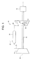
- Figure 1 is a schematic illustration of a gas turbine engine including a two-part cast engine component, shown in the form of a rotor blade, constructed in accordance with an aspect of the invention
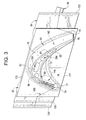
- Figure 2 is an enlarged perspective view of the rotor blade of Figure 1 ;
- Figure 3 is an end view of the rotor blade of Figure 1 ;
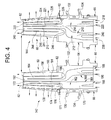
- Figure 4 is an elevational view showing two component sections of the rotor blade of Figure 1 prior to being joined.
- Turbine engine 10 includes a compressor 12 operatively coupled to a turbine 14 and an electrical generator 16 via a shaft 18.
- Shaft 18 is illustrated as a single, monolithic component, however, it should be readily understood that shaft 18 could also be formed in multiple segments with each segment being coupled to an adjacent engine component.
- engine 10 is further shown to include a combustor 20 in which air 21 from compressor 12 and a fuel 22 are mixed to form a combustible mixture.
- the combustible mixture is ignited to form a high pressure, high temperature combustion product or gas 28 that is used to drive turbine 14. More specifically, high pressure, high temperature gas 28 enters into turbine 14 and impinges upon a rotor assembly 35 having a plurality of rotor blades, two of which are indicated at 40 and 41.
- Rotor assembly 35 converts thermal energy from high pressure, high temperature gas 28 into mechanical, rotational, energy.
- rotor blades 40 and 41 When coupled to rotor assembly 35, rotor blades 40 and 41 are connected to a rotor disk (not shown) that is rotateably mounted to a rotor shaft, such as shaft 18. In an alternative configuration, rotor blades 40 and 41 are mounted within a rotor spool (not shown). In any event, circumferentially adjacent rotor blades 40 and 41 are identical such that a detailed description will follow referring to rotor blade 40. However, it should be understood that in the exemplary embodiment, each of the plurality of rotor blades is similarly constructed.
- rotor blade 40 includes an airfoil portion 60, a platform portion 62, a shank portion 64 and a dovetail 66 which are collectively known as a bucket.
- Each airfoil portion 60 includes a first sidewall 70 and a second sidewall 72.
- first sidewall 70 is convex and defines a suction side of airfoil portion 60.
- second sidewall 72 is concave and defines a pressure side of airfoil portion 60.
- Sidewalls 70 and 72 collectively form a leading edge 74 and an axially spaced trailing edge 76 of airfoil portion 60. More specifically, trailing edge 76 is spaced chord-wise and downstream from leading edge 74.
- leading edge 74 is provided with a plurality of openings 77 that serve as ventilation ducts allowing a cooling gas to pass through rotor blade 40.
- trailing edge 76 includes a plurality of openings 78 that also serve as cooling gas ventilation ducts.
- First and second sidewalls 70 and 72 extend outward in span from a bucket or blade root 79 located adjacent to platform portion 62 to an airfoil tip 80.
- airfoil tip 80 includes an opening 82 defined by a recessed seat 84.
- a tip cap 85 is provided in recessed seat 84 and closes opening 82.
- tip cap 85 may be provided with small openings, such as indicated at 87 that allow a small portion of the cooling gas to pass into a hot gas path (not shown).
- shank portion 64 extends radially inward from platform portion 62 to dovetail 66, and dovetail 66 extends radially inward from shank portion 64 to facilitate securing rotor blade 40 to the rotor disk (not shown).
- Platform portion 62 also includes an upstream side or skirt 107 and a downstream side or skirt 109 that are connected by a pressure-side edge 111 and a suction-side edge 112.
- Shank portion 64 is shown to include a substantially concave side wall 120 and a substantially convex sidewall (not shown) that are connected at an upstream sidewall 124 and a downstream sidewall 126.
- concave sidewall 120 is recessed relative to upstream and downstream sidewalls 124 and 126 respectively, such that when rotor blade 40 is coupled within rotor assembly 35, a shank cavity 128 is defined between adjacent rotor blades 40 and 41.
- rotor blade 40 includes a forward angel wing 130 and an aft angel wing 132 which extend outward from upstream side wall 124 and downstream sidewall 126 respectively. Forward and aft angel wings 130 and 132 are configured to seal corresponding forward and aft angel wing cavities (not shown) defined within rotor assembly 35.
- rotor blade 40 includes a forward, lower angel wing 134 which extends outward from upstream sidewall 124 to facilitate sealing between rotor blade 40 and the rotor disk (not shown).
- rotor blade 40 is a multi-part, cast component of engine 10. More specifically, rotor blade 40 includes a first component section 142 and a second component section 144 which are cast separately and joined together along a parting line 150.
- first and second component sections 142 and 144 are cast from aluminum.
- component sections 142 and 144 can be formed from a variety of materials, such as super alloys, and through a variety of known forming techniques.
- first component section 142 includes a main body portion 160 having a interior portion 162 that defines first and second cooling gas passage sections 164 and 165.
- first cooling gas passage section 164 includes an inlet section 168 which, in the exemplary embodiment, is bifurcated and leads into a flow chamber 170.
- Flow chamber 170 empties into a first flow section 171 that extends longitudinally through interior portion 162 to a first flow reversing section 172.
- first cooling flow passage section 164 leads to a flow return section 174 that extends longitudinally back through interior portion 162.
- Flow return section 174 terminates in a second flow reversing section 176 that leads to an outlet flow section 178.
- Outlet flow section 178 delivers cooling gas through openings 77 in leading edge 74 as well as openings 87 in airfoil tip 80.
- second cooling flow passage section 165 includes an inlet section 188 which, in the exemplary embodiment, is bifurcated and leads into a flow chamber 190.
- Flow chamber 190 empties into a first flow section 191 that extends longitudinally through interior portion 162 to a first flow reversing section 192.
- second cooling flow passage section 165 leads to a flow return section 194 that extends longitudinally back through interior portion 162.
- Flow return section 194 terminates in a second flow reversing section 196 that leads to an outlet flow section 198.
- Outlet flow section 198 delivers cooling gas through openings 78 in trailing edge 76 as well as openings 82 in airfoil tip 80.
- second component section 144 includes a main body portion 210 having a interior portion 212 that defines third and fourth cooling flow passage sections 214 and 215.
- Second component section 144 is actually a mirror image of first component section 142.
- third cooling flow passage section 214 is a mirror image of first cooling flow passage section 164 while fourth cooling flow passage section 215 is a mirror image of second cooling flow passage section 165.
- third cooling flow passage section 214 includes an inlet section 218 which, in the exemplary embodiment, is bifurcated and leads into a flow chamber 220.
- Flow chamber 220 empties into a first flow section 221 that extends longitudinally through interior portion 212 to a first flow reversing section 222. From first flow reversing section 222, third cooling flow passage section 214 leads to a flow return section 224 that extends longitudinally back through interior portion 212. Flow return section 224 terminates in a second flow reversing section 226 that leads to an outlet flow section 228. Outlet flow section 228 delivers cooling gas through openings 77 in leading edge 74 as well as openings 87 in airfoil tip 80.
- fourth cooling flow passage section 215 includes an inlet section 238 which, in the exemplary embodiment, is bifurcated and leads into a flow chamber 240.
- Flow chamber 240 empties into a first flow section 241 that extends longitudinally through interior portion 212 to a first flow reversing section 242.
- first flow reversing section 242 From first flow reversing section 242, fourth cooling flow passage section 215 leads to a flow return section 244 that extends longitudinally back through interior portion 212.
- Flow return section 244 terminates in a second flow reversing section 246 that leads to an outlet flow section 248.
- Outlet flow section 248 delivers cooling gas through openings 78 in trailing edge 76 as well as openings 82 in airfoil tip 80.
- cooling flow passages 164, 165 and 214, 215 are formed in respective first and second component sections 142 and 144 using a variety of techniques such as machining, molding and the like. Regardless of the technique employed, once formed, cooling flow passage sections 164, 165 and 214, 215 can be readily visually inspected for irregularities, which might detract from overall cooling efficiency.
- first and second component sections 142 and 144 are joined along parting line 150 so that first cooling flow passage section 164 registers with third cooling flow passage section 214 to form a first cooling flow channel 300 in rotor blade 40.
- second cooling flow passage section 165 registers with fourth cooling flow passage section 215 to form a second cooling flow channel 304 in rotor blade 40.
- Component sections 142 and 144 can be joined by a variety of known metal joining techniques such as welding, brazing and the like. Of course, if a super alloy or a material other than metal is used to form rotor blade 40, other joining techniques would be employed. In any event, once formed, rotor blade 40 is incorporated into rotor blade assembly 35 of a turbine engine 2.
- cooling channels can now be created that include thick and thin portions or even alternating thick and thin portions.
- present invention enables the formation of extremely small channels that can advantageously deliver a cooling gas to portions of the rotor blade heretofore unreachable by present passage formation techniques. More intricate serpentine shapes that carry the cooling medium through a larger portion of the component are also now possible. Ceramic core molding also has a tendency to react negatively with certain metals. The present invention avoids these problems.
- the present invention enables close, visual, inspection of the component parts to check for voids or other casting defects that were heretofore undetectable. That is, existing ceramic core molding is not capable of forming channels having differing dimensions or passages that are extremely thin or possess other such characteristics. When using ceramic core molding techniques, once the channels are formed, the ceramic core must be carefully removed. Removing a ceramic core from channels that are thick and thin or extremely narrow is not possible without risking breakage. If the core breaks, the rotor blade must be discarded.
- first and second cooling flow passages are shown to be similar, various other configurations could also be employed without detracting from the invention.
- the component is described as being cast from aluminum, other metals including super alloys and non-metals can also be used depending on the particular application of the engine. It should also be understood that while described as a rotor blade, various other engine components such as vanes, buckets, nozzles and the like could also be formed by the present invention.
- the component could be cast in any number of parts and should not be seen as being limited to the two component sections as shown. In general, the invention is only intended to be limited by the scope of the following claims.
Landscapes
- Engineering & Computer Science (AREA)
- Mechanical Engineering (AREA)
- General Engineering & Computer Science (AREA)
- Turbine Rotor Nozzle Sealing (AREA)
Abstract
Description
- The present invention pertains to the art of turbine engines and, more particularly, to a two part cast turbine engine component having internally formed cooling cavities.
- In general, gas turbine engines combust a fuel/air mixture to release heat energy in the form of a high temperature gas stream that is channeled to a turbine section via a hot gas path. More specifically, a compressor compresses incoming air to a high pressure. The high pressure air is delivered to a combustion chamber to mix with fuel and form a combustible mixture. The combustible mixture is then ignited to form a high pressure, high velocity gas stream which is delivered to the turbine. The high pressure air impacts upon rotor blades or buckets that form part of a turbine rotor assembly. In this manner, the turbine converts thermal energy from the high temperature, high velocity gas stream to mechanical energy that rotates a turbine shaft.
- In many cases, a cooling gas is delivered to internal portions of each rotor blade in order to lower temperatures, particularly in air foil portions of the rotor blade. The cooling gas is delivered through internal passages integrally molded with the blade. In some cases, the passages are formed using a lost wax investment casting method. In other cases, the passages are formed around a ceramic core. In either case, the passages are difficult to manufacture, expensive, and limited in shape. In addition, ceramic cores can react negatively with various alloys used in creating the blades. Moreover, ceramic cores are fragile and prone to shifting and breakage. Finally, internal surfaces of the passages may contain residual core defects, bad grain orientation or finning. The above manufacturing methods make visual inspection of the passages difficult, if not impossible.
- In accordance with one aspect, the present invention provides a multi-part cast component for a turbine engine. The multi-part cast component includes a first component section having a main body portion including a interior portion that defines a first cooling flow passage and a second component section having a main body portion including a interior portion that defines a second cooling flow passage section. The first and second component sections are joined along a parting line to form a turbine engine component with the first and second cooling flow passage sections aligning to form a cooling flow channel.
- In accordance with another aspect, the present invention provides a method of forming a multi-part cast component for a turbine engine. The method includes casting a first component section, forming a first cooling flow passage section in the first component section, casting a second component section and forming a second cooling flow passage section in the second turbine component section. The method also requires joining the first and second component sections along a parting line to form a turbine engine component, with the first and second cooling flow passage sections aligning to establish a cooling flow channel.
- It should be appreciated that the present invention provides a two part cast turbine engine component having an interior cooling channel whose formation is readily formed and which can be easily visually inspected while avoiding many of the drawbacks associated with other casting methods. In any event, additional objects, features and advantages of the various aspects of the present invention will become more readily apparent from the following detailed description of embodiments provided by way of example only when taken in conjunction with the drawings wherein like reference numerals refer to corresponding parts in the several views.
-
Figure 1 is a schematic illustration of a gas turbine engine including a two-part cast engine component, shown in the form of a rotor blade, constructed in accordance with an aspect of the invention; -
Figure 2 is an enlarged perspective view of the rotor blade ofFigure 1 ; -
Figure 3 is an end view of the rotor blade ofFigure 1 ; and -
Figure 4 is an elevational view showing two component sections of the rotor blade ofFigure 1 prior to being joined. - With initial reference to
Figure 1 , a gas turbine engine constructed in accordance with the present invention is generally indicated at 10.Turbine engine 10 includes acompressor 12 operatively coupled to aturbine 14 and anelectrical generator 16 via ashaft 18.Shaft 18 is illustrated as a single, monolithic component, however, it should be readily understood thatshaft 18 could also be formed in multiple segments with each segment being coupled to an adjacent engine component. - In any event,
engine 10 is further shown to include acombustor 20 in whichair 21 fromcompressor 12 and afuel 22 are mixed to form a combustible mixture. The combustible mixture is ignited to form a high pressure, high temperature combustion product orgas 28 that is used to driveturbine 14. More specifically, high pressure,high temperature gas 28 enters intoturbine 14 and impinges upon arotor assembly 35 having a plurality of rotor blades, two of which are indicated at 40 and 41.Rotor assembly 35 converts thermal energy from high pressure,high temperature gas 28 into mechanical, rotational, energy. - When coupled to
rotor assembly 35,rotor blades shaft 18. In an alternative configuration,rotor blades adjacent rotor blades rotor blade 40. However, it should be understood that in the exemplary embodiment, each of the plurality of rotor blades is similarly constructed. - As best shown in
Figures 2 and3 ,rotor blade 40 includes anairfoil portion 60, aplatform portion 62, ashank portion 64 and adovetail 66 which are collectively known as a bucket. Eachairfoil portion 60 includes afirst sidewall 70 and asecond sidewall 72. In the embodiment shown,first sidewall 70 is convex and defines a suction side ofairfoil portion 60. Conversely,second sidewall 72 is concave and defines a pressure side ofairfoil portion 60.Sidewalls edge 74 and an axially spacedtrailing edge 76 ofairfoil portion 60. More specifically,trailing edge 76 is spaced chord-wise and downstream from leadingedge 74. - As will be discussed more fully below, leading
edge 74 is provided with a plurality ofopenings 77 that serve as ventilation ducts allowing a cooling gas to pass throughrotor blade 40. Likewise,trailing edge 76 includes a plurality ofopenings 78 that also serve as cooling gas ventilation ducts. First andsecond sidewalls blade root 79 located adjacent toplatform portion 62 to anairfoil tip 80. As best shown inFigure 3 ,airfoil tip 80 includes anopening 82 defined by arecessed seat 84. Atip cap 85 is provided in recessedseat 84 and closes opening 82. However,tip cap 85 may be provided with small openings, such as indicated at 87 that allow a small portion of the cooling gas to pass into a hot gas path (not shown). - In the embodiment shown,
shank portion 64 extends radially inward fromplatform portion 62 todovetail 66, anddovetail 66 extends radially inward fromshank portion 64 to facilitate securingrotor blade 40 to the rotor disk (not shown).Platform portion 62 also includes an upstream side orskirt 107 and a downstream side orskirt 109 that are connected by a pressure-side edge 111 and a suction-side edge 112.Shank portion 64 is shown to include a substantiallyconcave side wall 120 and a substantially convex sidewall (not shown) that are connected at anupstream sidewall 124 and a downstream sidewall 126. In this manner,concave sidewall 120 is recessed relative to upstream anddownstream sidewalls 124 and 126 respectively, such that whenrotor blade 40 is coupled withinrotor assembly 35, ashank cavity 128 is defined betweenadjacent rotor blades - As further shown in
Figures 2 and3 ,rotor blade 40 includes aforward angel wing 130 and anaft angel wing 132 which extend outward fromupstream side wall 124 and downstream sidewall 126 respectively. Forward andaft angel wings rotor assembly 35. In addition,rotor blade 40 includes a forward,lower angel wing 134 which extends outward fromupstream sidewall 124 to facilitate sealing betweenrotor blade 40 and the rotor disk (not shown). - In accordance with one aspect of the present invention,
rotor blade 40 is a multi-part, cast component ofengine 10. More specifically,rotor blade 40 includes afirst component section 142 and asecond component section 144 which are cast separately and joined together along aparting line 150. In accordance with an exemplary embodiment, first andsecond component sections component sections - Reference will now be made to
Figure 4 is describing first andsecond component sections rotor blade 40. As shown,first component section 142 includes amain body portion 160 having ainterior portion 162 that defines first and second coolinggas passage sections gas passage section 164 includes aninlet section 168 which, in the exemplary embodiment, is bifurcated and leads into aflow chamber 170.Flow chamber 170 empties into afirst flow section 171 that extends longitudinally throughinterior portion 162 to a firstflow reversing section 172. From firstflow reversing section 172, first coolingflow passage section 164 leads to aflow return section 174 that extends longitudinally back throughinterior portion 162.Flow return section 174 terminates in a secondflow reversing section 176 that leads to anoutlet flow section 178.Outlet flow section 178 delivers cooling gas throughopenings 77 in leadingedge 74 as well asopenings 87 inairfoil tip 80. - In a manner similar to that described above, second cooling
flow passage section 165 includes aninlet section 188 which, in the exemplary embodiment, is bifurcated and leads into aflow chamber 190.Flow chamber 190 empties into afirst flow section 191 that extends longitudinally throughinterior portion 162 to a firstflow reversing section 192. From firstflow reversing section 192, second coolingflow passage section 165 leads to aflow return section 194 that extends longitudinally back throughinterior portion 162.Flow return section 194 terminates in a secondflow reversing section 196 that leads to anoutlet flow section 198.Outlet flow section 198 delivers cooling gas throughopenings 78 in trailingedge 76 as well asopenings 82 inairfoil tip 80. At this point it should be understood that while first and second coolingflow passage sections cooling passage section rotor blade 40. - In a manner similar to that described above with respect to
first component section 142,second component section 144 includes amain body portion 210 having ainterior portion 212 that defines third and fourth coolingflow passage sections Second component section 144 is actually a mirror image offirst component section 142. Accordingly, third coolingflow passage section 214 is a mirror image of first coolingflow passage section 164 while fourth coolingflow passage section 215 is a mirror image of second coolingflow passage section 165. However, for the sake of completeness, third coolingflow passage section 214 includes aninlet section 218 which, in the exemplary embodiment, is bifurcated and leads into aflow chamber 220.Flow chamber 220 empties into afirst flow section 221 that extends longitudinally throughinterior portion 212 to a firstflow reversing section 222. From firstflow reversing section 222, third coolingflow passage section 214 leads to aflow return section 224 that extends longitudinally back throughinterior portion 212.Flow return section 224 terminates in a secondflow reversing section 226 that leads to anoutlet flow section 228.Outlet flow section 228 delivers cooling gas throughopenings 77 in leadingedge 74 as well asopenings 87 inairfoil tip 80. - Also in a similar manner, fourth cooling
flow passage section 215 includes aninlet section 238 which, in the exemplary embodiment, is bifurcated and leads into aflow chamber 240.Flow chamber 240 empties into afirst flow section 241 that extends longitudinally throughinterior portion 212 to a firstflow reversing section 242. From firstflow reversing section 242, fourth coolingflow passage section 215 leads to aflow return section 244 that extends longitudinally back throughinterior portion 212.Flow return section 244 terminates in a secondflow reversing section 246 that leads to anoutlet flow section 248.Outlet flow section 248 delivers cooling gas throughopenings 78 in trailingedge 76 as well asopenings 82 inairfoil tip 80. - With this arrangement, cooling
flow passages second component sections flow passage sections second component sections parting line 150 so that first coolingflow passage section 164 registers with third coolingflow passage section 214 to form a firstcooling flow channel 300 inrotor blade 40. Similarly, second coolingflow passage section 165 registers with fourth coolingflow passage section 215 to form a secondcooling flow channel 304 inrotor blade 40.Component sections rotor blade 40, other joining techniques would be employed. In any event, once formed,rotor blade 40 is incorporated intorotor blade assembly 35 of a turbine engine 2. - At this point it should be understood that the various aspects of the present invention lower manufacturing costs and improve overall component quality. In addition, by forming the component in multiple parts, new cooling channel shapes and designs are now possible. That is, cooling channels can now be created that include thick and thin portions or even alternating thick and thin portions. Moreover, the present invention enables the formation of extremely small channels that can advantageously deliver a cooling gas to portions of the rotor blade heretofore unreachable by present passage formation techniques. More intricate serpentine shapes that carry the cooling medium through a larger portion of the component are also now possible. Ceramic core molding also has a tendency to react negatively with certain metals. The present invention avoids these problems. Finally the present invention enables close, visual, inspection of the component parts to check for voids or other casting defects that were heretofore undetectable. That is, existing ceramic core molding is not capable of forming channels having differing dimensions or passages that are extremely thin or possess other such characteristics. When using ceramic core molding techniques, once the channels are formed, the ceramic core must be carefully removed. Removing a ceramic core from channels that are thick and thin or extremely narrow is not possible without risking breakage. If the core breaks, the rotor blade must be discarded.
- Although described with reference to illustrated aspects of the present invention, it should be readily understood that various changes and/or modifications can be made to the invention without departing from the scope thereof. For instance, while the first and second cooling flow passages are shown to be similar, various other configurations could also be employed without detracting from the invention. Also, while the component is described as being cast from aluminum, other metals including super alloys and non-metals can also be used depending on the particular application of the engine. It should also be understood that while described as a rotor blade, various other engine components such as vanes, buckets, nozzles and the like could also be formed by the present invention. Finally, the component could be cast in any number of parts and should not be seen as being limited to the two component sections as shown. In general, the invention is only intended to be limited by the scope of the following claims.
Claims (11)
- A multi -part cast component for a turbine engine comprising:a first component section having a main body portion including at least one cooling flow passage section; anda second component section having a main body portion including at least one cooling flow passage section, said second component section being joined to the first component section along a parting line to form a turbine engine component with the at least one cooling flow passage section of the first component section aligning with the at least one cooling flow passage section of the second component section to form a cooling flow channel.
- The multi-part cast component according to claim 1, wherein the first and second component sections are joined to form a two-part turbine engine component.
- The multi-part cast component according to claim 1 or claim 2, wherein the first component section is a first rotor blade section and the second component section is a second rotor blade section, said first and second rotor blade sections being joined along the parting line to form a turbine rotor blade.
- The multi-part cast component according to any one of the preceding claims, wherein the at least one cooling flow passage section of the first component section includes first and second cooling flow passage sections.
- The multi-part cast component according to claim 3, wherein the at least one cooling flow passage section of the second component section includes third and fourth cooling flow passage sections, said first and third cooling flow passage sections being joined to form a first cooling flow channel and said second and fourth cooling flow passage sections being joined to form a second cooling flow channel.
- A method of forming a multi-part cast component for a turbine engine comprising:forming a first component section;creating at least one cooling flow passage section in the first component section;forming a second component section;creating at least one cooling flow passage section in the second component section; andjoining the first and second component section along a parting line to form a turbine engine component with said at least one cooling flow passage section of the first component section joining to the at least one cooling flow passage section of the second component section to form a cooling flow channel in the turbine component.
- The method of claim 6, wherein the turbine engine component is a turbine rotor blade.
- The method of claim 6 or claim 7, further comprising:forming first and second cooling flow passage sections in the first component section; andforming third and fourth cooling flow passage sections in the second component section wherein, upon joining the first and second component sections along the parting line, said first cooling flow passage section registers with the third cooling flow passage section to establish a first cooling flow channel and said second cooling flow passage section registers with the fourth cooling flow passage section to establish a second cooling flow channel in the turbine component.
- The method of any one of claims 6 to 8, wherein the at least one cooling flow passage section is machined from corresponding ones of the first and second component sections.
- The method of any one of claims 6 to 9, wherein the at least one cooling flow passage section is molded into corresponding ones of the first and second component sections.
- The method of any one of claims 6 to 10, wherein the turbine engine component is formed in two parts.
Applications Claiming Priority (1)
| Application Number | Priority Date | Filing Date | Title |
|---|---|---|---|
| US11/896,157 US20090060714A1 (en) | 2007-08-30 | 2007-08-30 | Multi-part cast turbine engine component having an internal cooling channel and method of forming a multi-part cast turbine engine component |
Publications (2)
| Publication Number | Publication Date |
|---|---|
| EP2031185A2 true EP2031185A2 (en) | 2009-03-04 |
| EP2031185A3 EP2031185A3 (en) | 2012-06-27 |
Family
ID=39717719
Family Applications (1)
| Application Number | Title | Priority Date | Filing Date |
|---|---|---|---|
| EP08162441A Withdrawn EP2031185A3 (en) | 2007-08-30 | 2008-08-14 | Multi-part cast turbine engine component having an internal cooling channel and method of forming a multi-part cast turbine engine component |
Country Status (4)
| Country | Link |
|---|---|
| US (1) | US20090060714A1 (en) |
| EP (1) | EP2031185A3 (en) |
| JP (1) | JP2009057968A (en) |
| CN (1) | CN101377132A (en) |
Families Citing this family (15)
| Publication number | Priority date | Publication date | Assignee | Title |
|---|---|---|---|---|
| US8007245B2 (en) * | 2007-11-29 | 2011-08-30 | General Electric Company | Shank shape for a turbine blade and turbine incorporating the same |
| CN101607300B (en) * | 2009-07-18 | 2013-07-10 | 大同北方天力增压技术有限公司 | Water-cooling and linked opening and starting type turbine wax injection die |
| US8915289B2 (en) * | 2011-05-10 | 2014-12-23 | Howmet Corporation | Ceramic core with composite insert for casting airfoils |
| US8899303B2 (en) | 2011-05-10 | 2014-12-02 | Howmet Corporation | Ceramic core with composite insert for casting airfoils |
| JP6245757B2 (en) * | 2014-05-22 | 2017-12-13 | 三菱日立パワーシステムズ株式会社 | COOLING DEVICE, GAS TURBINE EQUIPMENT HAVING THE SAME, AND COOLING DEVICE OPERATION METHOD |
| US20170074116A1 (en) * | 2014-07-17 | 2017-03-16 | United Technologies Corporation | Method of creating heat transfer features in high temperature alloys |
| US10252380B2 (en) | 2014-09-10 | 2019-04-09 | Mechanical Dynamics & Analysis Llc | Repair or remanufacture of blade platform for a gas turbine engine |
| US9828857B2 (en) | 2014-09-10 | 2017-11-28 | Pw Power Systems, Inc. | Repaired or remanufactured blade platform for a gas turbine engine |
| KR20180021166A (en) * | 2015-09-14 | 2018-02-28 | 미츠비시 히타치 파워 시스템즈 가부시키가이샤 | Manufacturing method of turbine rotor |
| US10472973B2 (en) | 2016-06-06 | 2019-11-12 | General Electric Company | Turbine component and methods of making and cooling a turbine component |
| CN109963961B (en) | 2016-11-16 | 2021-04-09 | 三菱动力株式会社 | Method for manufacturing nickel-based alloy high-temperature component |
| US20180161866A1 (en) | 2016-12-13 | 2018-06-14 | General Electric Company | Multi-piece integrated core-shell structure for making cast component |
| US11813669B2 (en) | 2016-12-13 | 2023-11-14 | General Electric Company | Method for making an integrated core-shell structure |
| US11021968B2 (en) * | 2018-11-19 | 2021-06-01 | General Electric Company | Reduced cross flow linking cavities and method of casting |
| US20240218828A1 (en) | 2022-11-01 | 2024-07-04 | General Electric Company | Gas Turbine Engine |
Citations (4)
| Publication number | Priority date | Publication date | Assignee | Title |
|---|---|---|---|---|
| GB926084A (en) * | 1962-01-11 | 1963-05-15 | Rolls Royce | Bladed member adapted for use on a fluid flow machine |
| GB2095589A (en) * | 1981-04-01 | 1982-10-06 | Rolls Royce | Method of making a blade for a gas turbine engine |
| JPH11114662A (en) * | 1997-10-09 | 1999-04-27 | Ishikawajima Harima Heavy Ind Co Ltd | Joining method for casting material and manufacture of turbine blade |
| US5993156A (en) * | 1997-06-26 | 1999-11-30 | Societe Nationale D'etude Et De Construction De Moteurs D'aviation Snecma | Turbine vane cooling system |
Family Cites Families (14)
| Publication number | Priority date | Publication date | Assignee | Title |
|---|---|---|---|---|
| DE1776015A1 (en) * | 1968-09-04 | 1971-09-16 | Daimler Benz Ag | Turbine blade |
| US4073599A (en) * | 1976-08-26 | 1978-02-14 | Westinghouse Electric Corporation | Hollow turbine blade tip closure |
| US4257737A (en) * | 1978-07-10 | 1981-03-24 | United Technologies Corporation | Cooled rotor blade |
| FR2516165B1 (en) * | 1981-11-10 | 1986-07-04 | Snecma | GAS TURBINE BLADE WITH FLUID CIRCULATION COOLING CHAMBER AND METHOD FOR PRODUCING THE SAME |
| US4815939A (en) * | 1986-11-03 | 1989-03-28 | Airfoil Textron Inc. | Twisted hollow airfoil with non-twisted internal support ribs |
| US5246340A (en) * | 1991-11-19 | 1993-09-21 | Allied-Signal Inc. | Internally cooled airfoil |
| DE10064267A1 (en) * | 2000-12-22 | 2002-07-04 | Alstom Switzerland Ltd | Process for quickly manufacturing hollow turbine blades for manufacturing development and component testing |
| US6491496B2 (en) * | 2001-02-23 | 2002-12-10 | General Electric Company | Turbine airfoil with metering plates for refresher holes |
| US6672836B2 (en) * | 2001-12-11 | 2004-01-06 | United Technologies Corporation | Coolable rotor blade for an industrial gas turbine engine |
| US6966756B2 (en) * | 2004-01-09 | 2005-11-22 | General Electric Company | Turbine bucket cooling passages and internal core for producing the passages |
| US7137780B2 (en) * | 2004-06-17 | 2006-11-21 | Siemens Power Generation, Inc. | Internal cooling system for a turbine blade |
| US7168921B2 (en) * | 2004-11-18 | 2007-01-30 | General Electric Company | Cooling system for an airfoil |
| US7311497B2 (en) * | 2005-08-31 | 2007-12-25 | United Technologies Corporation | Manufacturable and inspectable microcircuits |
| US8591189B2 (en) * | 2006-11-20 | 2013-11-26 | General Electric Company | Bifeed serpentine cooled blade |
-
2007
- 2007-08-30 US US11/896,157 patent/US20090060714A1/en not_active Abandoned
-
2008
- 2008-08-14 EP EP08162441A patent/EP2031185A3/en not_active Withdrawn
- 2008-08-28 JP JP2008218890A patent/JP2009057968A/en not_active Withdrawn
- 2008-08-29 CN CNA2008102142798A patent/CN101377132A/en active Pending
Patent Citations (4)
| Publication number | Priority date | Publication date | Assignee | Title |
|---|---|---|---|---|
| GB926084A (en) * | 1962-01-11 | 1963-05-15 | Rolls Royce | Bladed member adapted for use on a fluid flow machine |
| GB2095589A (en) * | 1981-04-01 | 1982-10-06 | Rolls Royce | Method of making a blade for a gas turbine engine |
| US5993156A (en) * | 1997-06-26 | 1999-11-30 | Societe Nationale D'etude Et De Construction De Moteurs D'aviation Snecma | Turbine vane cooling system |
| JPH11114662A (en) * | 1997-10-09 | 1999-04-27 | Ishikawajima Harima Heavy Ind Co Ltd | Joining method for casting material and manufacture of turbine blade |
Also Published As
| Publication number | Publication date |
|---|---|
| CN101377132A (en) | 2009-03-04 |
| JP2009057968A (en) | 2009-03-19 |
| US20090060714A1 (en) | 2009-03-05 |
| EP2031185A3 (en) | 2012-06-27 |
Similar Documents
| Publication | Publication Date | Title |
|---|---|---|
| EP2031185A2 (en) | Multi-part cast turbine engine component having an internal cooling channel and method of forming a multi-part cast turbine engine component | |
| EP2071126B1 (en) | Turbine blades and methods of manufacturing | |
| EP3216981B1 (en) | Radial turbine blade comprising a diverging-converging cooling passage | |
| US10934865B2 (en) | Cooled single walled blisk for gas turbine engine | |
| US10415403B2 (en) | Cooled blisk for gas turbine engine | |
| US10975705B2 (en) | Gas turbine engine airfoil with wishbone baffle cooling scheme | |
| EP3556999B1 (en) | Double wall airfoil cooling configuration for gas turbine engine | |
| US10247015B2 (en) | Cooled blisk with dual wall blades for gas turbine engine | |
| US11230929B2 (en) | Turbine component with dust tolerant cooling system | |
| EP3783197A1 (en) | Airfoil with rib having connector arms | |
| US6932570B2 (en) | Methods and apparatus for extending gas turbine engine airfoils useful life | |
| US11624322B2 (en) | Hourglass airfoil cooling configuration | |
| EP3623577B1 (en) | Gas turbine engine airfoil tip cooling arrangement with purge partition | |
| EP3594448B1 (en) | Airfoil with leading edge convective cooling system | |
| US11333042B2 (en) | Turbine blade with dust tolerant cooling system | |
| EP3670836A1 (en) | Airfoil platform with cooling orifices |
Legal Events
| Date | Code | Title | Description |
|---|---|---|---|
| PUAI | Public reference made under article 153(3) epc to a published international application that has entered the european phase |
Free format text: ORIGINAL CODE: 0009012 |
|
| AK | Designated contracting states |
Kind code of ref document: A2 Designated state(s): AT BE BG CH CY CZ DE DK EE ES FI FR GB GR HR HU IE IS IT LI LT LU LV MC MT NL NO PL PT RO SE SI SK TR |
|
| AX | Request for extension of the european patent |
Extension state: AL BA MK RS |
|
| PUAL | Search report despatched |
Free format text: ORIGINAL CODE: 0009013 |
|
| AK | Designated contracting states |
Kind code of ref document: A3 Designated state(s): AT BE BG CH CY CZ DE DK EE ES FI FR GB GR HR HU IE IS IT LI LT LU LV MC MT NL NO PL PT RO SE SI SK TR |
|
| AX | Request for extension of the european patent |
Extension state: AL BA MK RS |
|
| RIC1 | Information provided on ipc code assigned before grant |
Ipc: F01D 5/18 20060101AFI20120521BHEP |
|
| STAA | Information on the status of an ep patent application or granted ep patent |
Free format text: STATUS: THE APPLICATION IS DEEMED TO BE WITHDRAWN |
|
| 18D | Application deemed to be withdrawn |
Effective date: 20120301 |