EP4455441A1 - Rollladenflansch, montageteil, schutzanlage, insbesondere für rolladen, und montageverfahren dafür - Google Patents
Rollladenflansch, montageteil, schutzanlage, insbesondere für rolladen, und montageverfahren dafür Download PDFInfo
- Publication number
- EP4455441A1 EP4455441A1 EP24169877.8A EP24169877A EP4455441A1 EP 4455441 A1 EP4455441 A1 EP 4455441A1 EP 24169877 A EP24169877 A EP 24169877A EP 4455441 A1 EP4455441 A1 EP 4455441A1
- Authority
- EP
- European Patent Office
- Prior art keywords
- locking
- flange
- locking part
- fixing portion
- winding axis
- Prior art date
- Legal status (The legal status is an assumption and is not a legal conclusion. Google has not performed a legal analysis and makes no representation as to the accuracy of the status listed.)
- Granted
Links
Images


Classifications
-
- E—FIXED CONSTRUCTIONS
- E06—DOORS, WINDOWS, SHUTTERS, OR ROLLER BLINDS IN GENERAL; LADDERS
- E06B—FIXED OR MOVABLE CLOSURES FOR OPENINGS IN BUILDINGS, VEHICLES, FENCES OR LIKE ENCLOSURES IN GENERAL, e.g. DOORS, WINDOWS, BLINDS, GATES
- E06B9/00—Screening or protective devices for wall or similar openings, with or without operating or securing mechanisms; Closures of similar construction
- E06B9/02—Shutters, movable grilles, or other safety closing devices, e.g. against burglary
- E06B9/08—Roll-type closures
- E06B9/11—Roller shutters
- E06B9/17—Parts or details of roller shutters, e.g. suspension devices, shutter boxes, wicket doors, ventilation openings
- E06B9/174—Bearings specially adapted therefor
-
- E—FIXED CONSTRUCTIONS
- E06—DOORS, WINDOWS, SHUTTERS, OR ROLLER BLINDS IN GENERAL; LADDERS
- E06B—FIXED OR MOVABLE CLOSURES FOR OPENINGS IN BUILDINGS, VEHICLES, FENCES OR LIKE ENCLOSURES IN GENERAL, e.g. DOORS, WINDOWS, BLINDS, GATES
- E06B9/00—Screening or protective devices for wall or similar openings, with or without operating or securing mechanisms; Closures of similar construction
- E06B9/24—Screens or other constructions affording protection against light, especially against sunshine; Similar screens for privacy or appearance; Slat blinds
- E06B9/40—Roller blinds
- E06B9/42—Parts or details of roller blinds, e.g. suspension devices, blind boxes
- E06B9/50—Bearings specially adapted therefor
Definitions
- the present invention relates to a roller shutter flange, a roller shutter installation comprising such a flange and a method of assembling such a flange.
- these openings are generally equipped with a protection installation, for example against intrusions, with a screen such as a roller shutter, or a solar protection installation, with for example a screen such as a solar canvas, a roller shutter, a slatted blind or an adjustable sunshade, also known as "BSO", or even an anti-insect protection installation, with a mosquito net.
- a protection installation for example against intrusions
- a screen such as a roller shutter
- a solar protection installation with for example a screen such as a solar canvas, a roller shutter, a slatted blind or an adjustable sunshade, also known as "BSO”
- BSO adjustable sunshade
- the protective screen is attached to a tube, which is housed in a receiving volume arranged in the upper part of an opening.
- the receiving volume is delimited by a casing of the roller shutter installation, or is arranged directly in the wall, for example in a lintel, etc.
- the tube comprises two end bearings, which are each supported by a flange, so that the tube is pivotally mounted, relative to the flanges, around a winding axis.
- the flanges are integral with the wall, generally fixed to other elements of the protective installation, in particular each fixed to a respective guide slide of the protective screen.
- the installation generally includes a motor, which is housed in the tube and whose pivoting head protrudes from the tube, this head being fixed to the flange.
- FR-2 917 452-A1 describes, for example, a flange comprising an attached plate, the plate having an orifice for receiving an axis of the tube. The axis is locked to the plate by means of a spring pin, which risks being lost and the installation of which can be difficult, because it requires perfect alignment of the parts.
- FR-3 126 137-A1 describes, for its part, a roller shutter flange with a pendulum lock comprising relatively fragile indexing members.
- the invention seeks to address more specifically by proposing a roller shutter flange which allows easier fixing of the end bearing of the winding tube.
- the invention relates to a roller shutter flange, which is configured to support a winding tube of a protection installation.
- a protection installation 10 is schematically represented on the figure 1 .
- Installation 10 is here an intrusion protection installation, which includes a roller shutter. Protection installation 10 is therefore here a roller shutter installation.
- the installation 10 is fixed on a wall 12, assumed to be flat and vertical, in which an opening 14 is provided which passes through the wall 12.
- the opening 14 is here hidden by a protective screen 24, which belongs to the protective installation 10.
- the protective screen 24 is here a roller shutter apron. According to non-limiting alternatives, the screen 24 is a solar canvas, or even a mosquito net, etc.
- the installation 10 here comprises a trunk 18, which is here schematically represented in dotted lines.
- the trunk 18 is fixed to the wall 12, above the opening 14.
- the trunk 18 has an elongated, generally parallelepiped shape and extends in its length along a trunk axis A18.
- the trunk axis A18 is assumed to be horizontal. The description is made in relation to the orientation of the parts of the installation 10 as shown in the drawings, knowing that it may be otherwise in reality.
- the installation 10 has a structure that is generally symmetrical with respect to a transverse plane T18 of the installation, the transverse plane T18 being orthogonal to the trunk axis A18.
- the trunk 18 provides a receiving volume V18 for other parts of the installation 10, as described below.
- the trunk 18 is manufactured by assembling boards.
- the receiving volume V18 is delimited in part by the wall 12, for example is managed in the wall 12, in particular in a lintel delimiting the opening 14 in the upper part of the opening 14.
- This configuration corresponds to a so-called “half-lintel” assembly.
- the receiving volume V18 is essentially contained in the lintel, according to a so-called “lintel” assembly configuration.
- the installation 10 comprises a tube 20, which is here a winding tube of the screen 24, and two supports 30, which are integral with the wall 12 and which are configured to support the tube 20.
- the two supports 30 are arranged symmetrically with respect to the transverse plane T18 of the installation 10, the two supports 30 having overall a symmetrical structure with respect to each other. What is valid for one of the two supports 30 is transposable to the other support 30.
- the tube 20 comprises two opposite ends, each of which is provided with an end bearing 22.
- Each of the end bearings 22 is supported by a respective bracket 30, such that the tube 20 is pivotally mounted relative to the brackets 30, about the trunk axis A18.
- An upper end 25A of the screen 24 is attached to the tube 20, here by means of two locks 26 belonging to the installation 10. It is understood that depending on the direction of rotation of the tube 20 around the trunk axis A18, the screen 24 winds around the tube 20, or unwinds, a lower end 25B of the screen 24 rising or falling in front of the opening 14. By extension, the trunk axis A18 is also a winding axis of the tube 20.
- the rotation of the tube 20 is controlled by a user by means of a drive device.
- the drive device is not shown.
- the drive device is either manual, for example with a crank and a gear system or with a belt device, or motorized, with an electric motor.
- a part of the motor is generally received in the tube 20, while a pivoting head of the motor protrudes from the tube and forms one of the bearings of the tube.
- Each support 30 is secured to the wall 12, i.e. fixed to the wall 12, either directly or via another element of the installation 10.
- each support 30 is fixed to a respective slide 32, the slide 32 being fixed to the wall 12.
- the installation 10 thus comprises two slides 32, which are located opposite one another, symmetrically with respect to the transverse plane T18.
- Each slide 32 extends vertically along one side of the opening 14, the two slides 32 serving to guide the screen 24, in particular during the movements of raising or lowering the lower end 25B of the screen 24.
- each bearing 22 comprises a part with a star shape, which is received in a complementary shaped imprint formed in the support 30.
- Each bearing 22 thus received in the complementary imprint is blocked in rotation, relative to the support 30, around the winding axis A18.
- the shape of the bearing 22 is not limiting, as long as the bearing 22 is blocked in rotation when it is in the imprint 312.
- the star-shaped imprint 312 receives the end bearing 22 of the winding tube 20.
- the flange 300 is configured to receive any type of part having a shape compatible with the imprint 312, in particular an adaptation part, as described in the published application. FR-3 118 479-A1 .
- the support 30 shown on the right of the figure 1 is shown on a larger scale, with the associated slide 32 and the associated end bearing 22, on the figure 2 . The remainder of the description being made with reference to this support 30.
- Each support 30 comprises a leg 100, a tulip 200 and a flange 300.
- the tab 100 is here formed in a metal plate, preferably made of steel.
- the tab 100 is for example manufactured by cutting.
- the tab 100 here comprises a fixing tenon 102, by which the tab 100 is configured to be assembled to the flange 300, and a fitting 104, by which the tab 100 is configured to be secured to the wall 12.
- the fitting 104 having a free end, which here has a tapered shape, and a captive end, which is opposite the free end and which is connected to the tenon 102.
- the tabs 100 are secured to the wall 12 by means of the slides 32, the fitting 104 of each tab 100 being fixed to a respective slide 32, which is fixed to the wall 12.
- the tulip 200 comprises an outer wall 202A and an inner wall 202B, which are arranged facing each other and which are connected to each other by a bottom 202C.
- the outer wall 202A and the inner wall 202B diverge from each other, hence the name “tulip”.
- the outer wall 202A, the inner wall 202B and the bottom 202C are configured to guide an edge of the protective screen 24 on a front side of the bottom 202C, so as to limit the friction of the screen 24 on the corresponding slide 32.
- the tulip 200 provides a conduit 204 for fitting the fitting 104.
- the tulip 200 comprises a first elastic clip 206 configured to cooperate, in particular by complementarity of shape, with a first orifice 106 provided in the fitting 104, so as to fix the tulip 200 to the fitting 104 when the fitting 104 is fitted into the conduit 204, in a fitted position of the tab 100 relative to the tulip 200.
- Each of the flanges 300 supports one of the end bearings 22 of the winding tube 20, such that the tube 20 is pivotally mounted relative to the flanges 300 about the winding axis A18.
- the flange 300 has a front face 302A, which is generally flat and which extends orthogonally to the winding axis A18, and a rear face 302B opposite the front face 302A.
- the flange 300 comprises a fixing portion 310, which comprises an imprint 312, configured to receive one of the end bearings 22 of the winding tube 20.
- the front face 302A faces the tube 20 when the tube 20 is assembled to the support 30.
- the flange 300 also comprises a peripheral portion 350, which is configured to be secured to the rest of the roller shutter installation 10 and in which a slot 352 is provided for receiving the fixing portion 310.
- the slot 352 which here has the shape of an oblong hole, comprises two opposite straight edges 352A and 352B which are parallel to an adjustment axis A352.
- the shape of the slot 352 is not limiting.
- the fixing portion 310 is configured to be assembled to the peripheral portion 350 by being received in the lumen 352 in an assembled configuration of the flange 300.
- the fixing portion 310 is here made of synthetic polymer material, and is preferably produced by hot injection.
- the peripheral portion 350 is here made of a metal plate, preferably steel, and is produced in particular by cutting and/or stamping.
- the fixing portion 310 is advantageously adjustable in position relative to the peripheral portion 350 along the adjustment axis A352. It is thus possible to adjust a position of the tube 20 relative to the supports 30, during the assembly of the installation 10, in particular according to the size of the screen 24.
- the fixing portion 310 comprises a wall 314, which defines the imprint 312.
- the wall 314, and by extension the imprint 312, have a cylindrical shape centered on the winding axis A18 when the fixing portion 310 is assembled, the wall 314 delimiting an internal volume V314 which is configured to receive one of the end bearings 22 of the winding tube 20 according to an insertion movement F312 of the bearing 22 in the imprint 312.
- the wall 314 has an internal side, oriented towards the side of the internal volume V314, and an external side, oriented opposite the internal side.
- the insertion movement F312 which is represented by an arrow at the figure 3 , is a translational movement parallel to the winding axis A18.
- the bearing 22 has a shape complementary to the imprint 312, so that the bearing 22 is blocked in rotation relative to the fixing portion 310, and by extension relative to the flange 300, around the winding axis A18.
- the flange 30 incorporates a locking device, which facilitates the assembly of the bearing 22 to the flange 30.
- the fixing portion 310 also comprises an opening 380, which is formed through the wall and which opens into the internal volume.
- the fixing portion 310 comprises three openings 316, which are regularly distributed around the winding axis A18.
- the flange 300 also comprises a locking part 380, which here generally has the shape of a ring 382 with a control tab 384.
- the control tab 384 is connected to the ring 382 and is configured to be actuated by an installer, so as to control the movements of the locking part 380.
- the locking part 380 is here made of synthetic polymer material, and is preferably produced by hot injection. Alternatively, the locking part is produced by stamping a metal sheet, alternatively made of polymer.
- the ring 382 is arranged on an outer side of the wall 314 and cooperates with the wall 314, in particular by sliding surfaces, so that the ring 382 is guided in rotation relative to the fixing portion 310 around the winding axis A18.
- the ring 382 comprises an internal radial surface 385, which is geometrically carried by a cylinder of circular section centered on the winding axis A18, while the wall 314 has, on the outer side, an external radial surface 315, which is geometrically carried by a cylinder of circular section centered on the winding axis A18 and which has a diameter substantially equal, apart from assembly clearances, to a diameter of the internal radial surface 385 of the ring.
- the locking part 380 comprises at least one protrusion 386, which is provided in a projecting manner on the ring 382 and which extends from the ring 382 in a centripetal manner to the winding axis A18.
- each protrusion 386 extends in a projecting manner from the inner radial surface 385 towards the winding axis A18.
- Each protrusion 386 is associated with a respective opening 316.
- the locking part 380 is movable relative to the fixing portion 310 between a locking position, in which each protrusion 386 of the locking part 380 protrudes from the associated opening 316 into the internal volume V314 of the imprint 312, and a withdrawn position, in which each protrusion 386 does not protrude into the internal volume V314 of the imprint 312.
- the locking part 380 is in the locking position, the subassembly formed by the fixing portion 310 and the locking part 380 is then in a locking configuration.
- the locking part 380 is in the withdrawn position, the subassembly formed by the fixing portion 310 and the locking part 380 is then in a withdrawn configuration. Moving the locking part 380 from the retracted position to the locking position is a locking movement, while moving the locking part 380 from the locking position to the retracted position is an unlocking movement.
- Each protrusion 386 is configured to be received in a complementary recess 22A, provided in the bearing 22, so as to prevent movements translation of the bearing 22 relative to the fixing portion when the bearing is received in the imprint and the locking part is in the locking position.
- Each protuberance 386 thus forms a blocking portion of the locking part 380.
- each opening 316 is arranged in a plane transverse to the winding axis A18.
- the ring 382 is guided in rotation relative to the fixing part 310, so the locking and retracted positions are angular positions of the ring 382 relative to the fixing portion 310 around the winding axis A18.
- the control tab 384 thus allows the installer to move the locking part 380 between its retracted position and its locking position.
- the flange 300 advantageously comprises inscriptions 304, for example pictograms and/or alphanumeric characters, which are arranged so as to indicate to the user, as a function of an angular position of the control tab 384 around the winding axis A18, whether the locking part 380 is in one or the other of the locking position or the withdrawn position.
- inscriptions 304 for example pictograms and/or alphanumeric characters, which are arranged so as to indicate to the user, as a function of an angular position of the control tab 384 around the winding axis A18, whether the locking part 380 is in one or the other of the locking position or the withdrawn position.
- the inscriptions 304 are engravings, which are located on the peripheral portion 350 and which here represent a closed padlock and an open padlock.
- the fixing portion 310 and the peripheral portion 350 each comprise a front face, which together form the front face 302A of the flange 300 when the fixing portion 310 is assembled to the peripheral portion 350, as shown in figure 2 , where the flange is in a so-called “engaged” configuration.
- the flange 300 comprises stop means, which are arranged in at least one of the elements chosen from the peripheral portion 350 and the fixing portion 310.
- the stop means are configured to limit the relative movements of the fixing portion 310 with respect to the peripheral portion 350 to translational movements along the mounting axis A352 when the stop means are in an engaged configuration, the flange then being in the engaged configuration.
- the stop means comprise a peripheral rim 354, which is provided on the peripheral portion 350 at the edge of the light 352.
- the peripheral rim 354 includes two straight segments 354A and 354B, which are each provided set back from the front face of the peripheral portion 350 and which form the straight edges 352A and 352B of the light 352.
- the peripheral rim 354 is here discontinuous, so as not to generate the movements of the tab 384.
- the stop means also comprise two complementary segments 332A and 332B, which are arranged on the fixing portion 310, each complementary segment 332A or 332B being configured to cooperate, in particular by complementarity of shapes, so as to slide against a respective straight segment 354A or 354B when the flange 30 is in the engaged configuration.
- each complementary segment 332A or 332B being configured to cooperate, in particular by complementarity of shapes, so as to slide against a respective straight segment 354A or 354B when the flange 30 is in the engaged configuration.
- the front face of the fixing portion 310 is coplanar with the front face of the peripheral portion 350. This avoids the risks of interference with the screen 24 when using the installation 10.
- the arrangement and shape of the stop means are not limiting.
- the flange 300 also comprises adjustment means.
- the stop means and the adjustment means are configured such that, when assembling the fixing portion 310 to the peripheral portion 350, the fixing portion 310 is adjustable in position relative to the peripheral portion 350 along the adjustment axis A352.
- the adjustment means comprise notches 356, which are regularly distributed along at least one of the straight edges 352A or 352B of the light 352, the notches 356 arranged along the same edge forming a row 358 of notches.
- notches 356 are arranged along each of the straight edges 352A and 352B, the peripheral portion thus comprising two rows 358 of notches 356.
- the notches 356 here have a rectangular profile and are arranged by notches cut out in the straight segments 354A and 354B. Two successive notches 356 are thus separated by a notch, a step between two successive notches 354 being equal to a length, measured parallel to the adjustment axis A352, of one notch and one notch.
- the adjustment means also comprise teeth 336, which are arranged on the fixing portion 310 and which are configured to cooperate, by shape complementarity, with a portion of the notches 356, so as to prevent translational movements of the fixing portion 310 relative to the peripheral portion 350 along the adjustment axis A352 when the flange is in the engaged configuration.
- the teeth 336 are then engaged in some of the notches 356.
- the adjustment means are also said to be in an engaged configuration.
- the teeth 336 here each have a profile corresponding to the notches between two successive notches 356. Preferably, the teeth 336 have the same profile as the notches 356. In the example illustrated, several teeth 336 are provided along each straight segment 332A and 332B of the fixing portion 310, forming rows 338 of teeth 336.
- the position of the fixing portion 310 relative to the peripheral portion 350 along the adjustment axis A352 is adjustable incrementally, according to an adjustment step corresponding to a step between two notches. 356 successive.
- the adjustment pitch depends on the shape of the notches 356 and the teeth 336, which allows a finer adjustment compared to the devices known from the prior art, in particular an adjustment independent of the size of the imprint 312, which accommodates the bearing 22.
- the pitch between two successive notches 356 is equal to 10 mm, compared to a diameter of the star-shaped bearing 22, of the order of 60 mm.
- Each row 358 of notches 356 here has five notches, while each row 338 of teeth 336 here comprises three teeth 336. It is thus possible to choose between three different positions.
- inscriptions are provided on the flange 300, so as to indicate to the installer the position in which he must assemble the fixing portion 310 and the peripheral portion 350.
- the inscriptions are not shown.
- the fixing portion 310 is shown in exploded perspective with a portion of the bearing 22, which is configured to be received in the imprint 312.
- the wall 314 extends, parallel to the winding axis A18, between a front side, which is geometrically supported by a front plane transverse to the winding axis A18, and a rear side, which is opposite the front side and which is supported by a rear plane transverse to the winding axis A18.
- the fixing portion 310 comprises rear stops 320, which are integral with the wall 314, which are located on the external side of the wall 314 and which are carried by the rear plane.
- the rear stops 320 are here formed by ribs, which extend from the wall 314 on the external side of the wall 314.
- the ribs are here arranged regularly around the winding axis A18 and together form a sliding surface for the ring 382.
- the fixing portion 310 comprises front stops 322, which extend in projection from the front side of the wall 314, on the external side of the wall.
- the front stops 322 are here formed by parallelepipedal-shaped studs and are here three in number, the front stops here being arranged regularly around the winding axis A18.
- the front stops 322 are geometrically carried by the front plane and extend here from the external radial surface 315 of the fixing portion 310.
- the front stops 322 and the rear stops 320 are axially offset, along the winding axis A18, so as to form between them an annular volume V324 for receiving the ring 382. It is understood that when the ring 382 is received in the receiving volume V224, the ring 384 is movable in rotation relative to the fixing portion 310.
- the flange 300 is in a so-called “assembled” configuration when the ring 382 is received in the annular volume V324.
- the ring 382 comprises notches 388, which are here formed in a hollow on the internal radial surface 385. Each notch 388 is associated with a respective front stop 322, such that, when the flange 300 is in the assembled configuration and the ring 382 is in a so-called assembled position relative to the fixing portion 310, all the stops 322 are simultaneously aligned, along the winding axis A18, with the notches 388 associated with these stops.
- the locking part 380 when the locking part 380 is in the locking position, the locking part 380 is movable relative to the fixing portion 310 according to a disassembly movement F390, the disassembly movement being a translation movement parallel to the winding axis A18 oriented from the rear side of the wall to the front side of the wall.
- the disassembly movement F390 tends to move the locking part 380 away from the fixing portion 310, thereby disassembling the flange 300.
- the flange when the flange is in the assembled configuration, but the notches 388 are not aligned with the front stops 322, the disassembly movement F390 is prevented, in other words the ring 382 is captive in the annular volume V324.
- the locking and unlocking movements are each rotational movements of the locking part 380 relative to the fixing portion 310 around the winding axis A18.
- movements of the locking piece 380 between the assembled position, the removed position, and the locking position are preferably indexed.
- the indexing is accomplished by providing recesses 392 in the material of the securing portion 310, the recesses 392 being arranged to receive a portion of the tab 324 when the locking piece 380 is either in the assembled position, the locked position, or the removed position.
- the tab 384 When the flange 300 is in the assembled configuration and the installer actuates the tab 384 to pivot the locking piece 380 relative to the securing portion 310, the tab 384 generates a force that opposes movement of the locking piece 380, the user having to overcome this force to move the locking part, thus creating the indexing, which reduces the risks of accidental unlocking of the locking part 380.
- the locking of the bearing 22 in the imprint 312 is advantageously done by hand and without tools, without risk of losing the locking part 380, captive of the fixing portion 310.
- the indexing means thus operated are particularly robust, because they are arranged directly in the thickness of the material.
- the installer pivots the locking piece 380 preferably towards the withdrawn position for future assembly of the flange 300 with a bearing 22 of the winding tube 20, to form the mounting subassembly 400.
- the flange 300 and the bearing 22 are in the configuration of figures 1 , 2 And 8 .
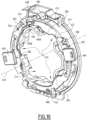
- a fixing portion 410 and a locking part 480, belonging to a flange according to a second embodiment of the invention, are shown in Figures 9 to 12 .
- elements similar to those in the first embodiment have the same references and operate in the same way.
- the differences between the first and second embodiments are mainly described.
- the fixing portion 410 and the locking part 480 form a subassembly of the flange according to the second embodiment of the invention.
- the locking part 380 has a ring shape 482, which here comprises two control tabs 484.
- the tabs 484 are diametrically opposed relative to the winding axis A18.
- the notches 388 are formed in a hollow on the internal radial surface 385 of the ring 382, as illustrated in particular in FIG. figure 4
- the ring 482 comprises notches 488, which are provided on an external radial surface 485 of the ring 482.
- the notches 488 are open in a centrifugal direction to the winding axis A18.
- the fixing portion 410 comprises a peripheral wall 414, which extends opposite the wall 314 delimiting the imprint 312 so as to delimit the annular volume V324.
- the fixing portion 410 comprises front stops 422, which are arranged in projection from the peripheral 414 in the direction of the winding axis A18, the front stops 422 being configured to cooperate with the notches 488, in a manner analogous to the cooperation of the front stops 322 and the notches 388 of the first embodiment.
- the locking part 480 here comprises three protrusions 386, which are arranged projecting from the ring 482 and which extend from the ring 482 towards the winding axis A18, in other words centripetally to the winding axis A18.
- the fixing portion 410 here comprises three openings 416, which are arranged through the wall 314 and which open into the internal volume V314.
- the locking part 480 comprises an axial protuberance 490, which is arranged as a projection on a front face 492 of the locking part 480, the front face 492 of the locking part 480 being oriented towards the front stops 422 when the locking part 480 is received in the annular volume V324.
- the axial protuberance 490 is associated with one of the front stops 422 and cooperates with the associated front stop 422, in particular by complementarity of shapes, so as to index the movements of the locking part 180 between the assembled position and the locking position.
- the axial protrusion 490 includes an upper face 494, which is configured to slide against the associated front stop 422 when the locking piece 480 is moved between the assembled position and the locking position.
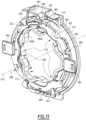
- the axial protuberance 490 advantageously has a ramp shape, which provides a front portion 496A and a rear portion 496B, which are angularly offset around the winding axis A18, the front portion 496A being opposite the associated front stop 422 when the locking part 480 is in the assembled position, as illustrated in FIG. figure 9 , while the rear portion 496B is opposite the associated front stop 422 when the locking part 480 is in the locking position, as illustrated in figure 11 .
- the locking part 480 is shown in an intermediate position between the assembled position and the locking position.
- a thickness of the front portion 496A is defined as being a distance, measured at the front portion 496A and parallel to the winding axis A18, between the upper face 494 and the front face 492 of the locking part 480.
- a thickness of the rear portion 496B is defined as being a distance, measured at the rear portion 496B and parallel to the winding axis A18, between the upper face 494 of the axial protuberance 490 and the front face 492 of the locking part 480,
- the axial protrusion 490 and the associated front stop 422 together form a non-return member, which prevents the disassembly of the locking part 480 once the locking part 480 is assembled to the portion 410, the locking part 480 being in the locking position or in the withdrawn position, or in an intermediate position between the locking position and the withdrawn position.
- the axial protuberance 490 cooperates with the associated front stop 422, in particular by complementarity of shapes, so as to index the movements of the locking part 480 between the assembled position and the locking position.
- the front portion 496A and the rear portion 496B have a similar thickness, while an intermediate portion of the axial protuberance 490, located between the front portion 496A and the rear portion 496B, has a thickness greater than that of the front portion 496A or the rear portion 496B.
- the flange 300 comprises the fixing portion 310 and the peripheral portion 350, which are separate parts.
- the structure of the flange is not limiting, and the principles of the invention can be transposed to other types of flange, for example when the fixing portion 310 is integral with the peripheral portion 350.
- the materials and manufacturing methods of the fixing portion 310 and the peripheral portion 350 are then adapted accordingly.
- the locking part 380 comprises the ring 382, which is captive to the connection portion 310, the movements of the locking part 380 relative to the connection portion 310 being a rotational movement about the winding axis A352.
- the structure of the locking part is not limiting.
- the locking part comprises a latch, which is captive to the fixing portion 310 and the movement of which relative to the fixing portion 310 is a translational movement in a plane orthogonal to the winding axis A18.
Landscapes
- Engineering & Computer Science (AREA)
- Structural Engineering (AREA)
- Architecture (AREA)
- Civil Engineering (AREA)
- Operating, Guiding And Securing Of Roll- Type Closing Members (AREA)
- Rollers For Roller Conveyors For Transfer (AREA)
Applications Claiming Priority (1)
| Application Number | Priority Date | Filing Date | Title |
|---|---|---|---|
| FR2303702A FR3147831B1 (fr) | 2023-04-13 | 2023-04-13 | Flasque de volet roulant, sous-ensemble de montage, installation de protection, notamment de volet roulant, et procédé d’assemblage associés |
Publications (2)
| Publication Number | Publication Date |
|---|---|
| EP4455441A1 true EP4455441A1 (de) | 2024-10-30 |
| EP4455441B1 EP4455441B1 (de) | 2026-02-18 |
Family
ID=87136850
Family Applications (1)
| Application Number | Title | Priority Date | Filing Date |
|---|---|---|---|
| EP24169877.8A Active EP4455441B1 (de) | 2023-04-13 | 2024-04-12 | Rollladenflansch, montageteil, und schutzanlage |
Country Status (2)
| Country | Link |
|---|---|
| EP (1) | EP4455441B1 (de) |
| FR (1) | FR3147831B1 (de) |
Citations (5)
| Publication number | Priority date | Publication date | Assignee | Title |
|---|---|---|---|---|
| DE20104119U1 (de) * | 2001-03-08 | 2001-04-26 | Schmitz, Dirk, 48703 Stadtlohn | Antriebslager |
| FR2917452A1 (fr) | 2007-06-12 | 2008-12-19 | Rene Le Nouy Soc Par Actions S | Systeme de liaison entre l'axe d'un volet roulant et une platine supportant l'axe |
| EP3216971A1 (de) * | 2016-03-10 | 2017-09-13 | Roma Kg | Gebäudeverschattungsvorrichtung und lageranordnung für deren wickelwelle |
| FR3118479A1 (fr) | 2020-12-24 | 2022-07-01 | Zurfluh Feller | Flasque de maintien d’un arbre d’une installation de protection, notamment de volet roulant, dispositif de maintien comprenant un tel flasque, sous-ensemble de montage et installation de protection associés |
| FR3126137A1 (fr) | 2021-08-10 | 2023-02-17 | Futurol | Dispositif de verrouillage de volet roulant et volet roulant comprenant un tel dispositif |
-
2023
- 2023-04-13 FR FR2303702A patent/FR3147831B1/fr active Active
-
2024
- 2024-04-12 EP EP24169877.8A patent/EP4455441B1/de active Active
Patent Citations (5)
| Publication number | Priority date | Publication date | Assignee | Title |
|---|---|---|---|---|
| DE20104119U1 (de) * | 2001-03-08 | 2001-04-26 | Schmitz, Dirk, 48703 Stadtlohn | Antriebslager |
| FR2917452A1 (fr) | 2007-06-12 | 2008-12-19 | Rene Le Nouy Soc Par Actions S | Systeme de liaison entre l'axe d'un volet roulant et une platine supportant l'axe |
| EP3216971A1 (de) * | 2016-03-10 | 2017-09-13 | Roma Kg | Gebäudeverschattungsvorrichtung und lageranordnung für deren wickelwelle |
| FR3118479A1 (fr) | 2020-12-24 | 2022-07-01 | Zurfluh Feller | Flasque de maintien d’un arbre d’une installation de protection, notamment de volet roulant, dispositif de maintien comprenant un tel flasque, sous-ensemble de montage et installation de protection associés |
| FR3126137A1 (fr) | 2021-08-10 | 2023-02-17 | Futurol | Dispositif de verrouillage de volet roulant et volet roulant comprenant un tel dispositif |
Also Published As
| Publication number | Publication date |
|---|---|
| EP4455441B1 (de) | 2026-02-18 |
| FR3147831B1 (fr) | 2025-06-06 |
| FR3147831A1 (fr) | 2024-10-18 |
Similar Documents
| Publication | Publication Date | Title |
|---|---|---|
| EP4019735A1 (de) | Flansch zum halten einer welle einer schutzanlage, insbesondere eines rollladens, entsprechende haltevorrichtung mit einem solchen flansch, montageunterbaugruppe und schutzanlage | |
| FR3115809A1 (fr) | Support d’arbre de volet roulant, installation de fermeture ou de protection solaire comprenant un tel support et procédé d’assemblage associé | |
| FR2907558A1 (fr) | Elements de charniere elastique a grande amplitude pour monture de lunettes | |
| EP3771800B1 (de) | System, das ein aufrollrohr eines rollladens und einen sperrriegel umfasst, und rollladenanlage, die ein solches system umfasst | |
| EP1728962B1 (de) | Vorrichtung zur Befestigung eines Rollladenvorhangs und Rollladen mit einer derartigen Vorrichtung | |
| EP4455441B1 (de) | Rollladenflansch, montageteil, und schutzanlage | |
| EP4455438B1 (de) | Rolladenrohrhalter, schutzeinrichtung, insbesondere für rolladen, und entsprechendes montageverfahren | |
| EP4455440B1 (de) | Rollladenflansch, schutzanlage und montageverfahren dafür | |
| FR3125310A1 (fr) | Coffre d’installation de protection, notamment de volet roulant, bloc-baie, installation de protection et procédé d’assemblage associés | |
| EP4123116B1 (de) | Führungsflansch für schutzblende, insbesondere für rollladen, montageuntereinheit mit einem solchen flansch, entsprechende schutzanlage und entsprechendes montageverfahren | |
| EP1983143A1 (de) | Aufrollvorrichtung für eine Tragschnur mit einer Führung für die Schnur | |
| EP1977070B1 (de) | Stützvorrichtung für rollo und mit solch einer vorrichtung zu versehene rolloanordnung | |
| FR2952611A1 (fr) | Etai notamment pour le soutien, l'appui et/ou la stabilisation de construction ou de structure et procede d'ajustement en longueur et de verrouillage a la longueur d'un tel etai | |
| EP4675078A1 (de) | Rollladenrohrhalter, zugehörige baugruppe sowie schutzanlage | |
| FR2901829A1 (fr) | Dispositif de montage d'au moins un vantail coulissant | |
| BE1032138B1 (fr) | Grille de sécurité pliable | |
| EP1160414A1 (de) | Endhalterung für eine Wickelwelle, Verfahren zur Herstellung und Antriebsmechanismus einer Schliess- oder Sonnenschutzeinrichtung mit solcher Vorrichtung | |
| FR3120384A1 (fr) | Flasque de support d’un arbre d’enroulement d’un écran de protection, sous-ensemble de montage et coffre comprenant un tel flasque, et installation de protection comprenant un tel coffre | |
| EP1262627B1 (de) | Flanschplatte für Rolladenkasten | |
| EP3643167B1 (de) | Rückhaltesystem für vieh, das einen durchgang mit einschliesst | |
| FR3116854A1 (fr) | Flasque de guidage d’écran de protection, notamment de volet roulant, installation de protection et procédé d’assemblage associés | |
| EP1312747A1 (de) | Teleskopisches Aufwickelrohr und Betätigungsvorrichtung für Rolladen oder Sonneschutz mit einem derartigen Rohr | |
| EP4159969B1 (de) | Einlauftrichter für einen vorhang, insbesondere einen rolladen, und entsprechende schutzanlage | |
| FR2907484A1 (fr) | Dispositif de blocage en position fermee d'un vantail coulissant dans un dormant | |
| FR3125312A1 (fr) | Tulipe de guidage d’un écran de protection, notamment de volet roulant, coffre, bloc-baie, installation de protection et procédé d’assemblage associés |
Legal Events
| Date | Code | Title | Description |
|---|---|---|---|
| PUAI | Public reference made under article 153(3) epc to a published international application that has entered the european phase |
Free format text: ORIGINAL CODE: 0009012 |
|
| STAA | Information on the status of an ep patent application or granted ep patent |
Free format text: STATUS: THE APPLICATION HAS BEEN PUBLISHED |
|
| AK | Designated contracting states |
Kind code of ref document: A1 Designated state(s): AL AT BE BG CH CY CZ DE DK EE ES FI FR GB GR HR HU IE IS IT LI LT LU LV MC ME MK MT NL NO PL PT RO RS SE SI SK SM TR |
|
| STAA | Information on the status of an ep patent application or granted ep patent |
Free format text: STATUS: REQUEST FOR EXAMINATION WAS MADE |
|
| 17P | Request for examination filed |
Effective date: 20250401 |
|
| GRAP | Despatch of communication of intention to grant a patent |
Free format text: ORIGINAL CODE: EPIDOSNIGR1 |
|
| STAA | Information on the status of an ep patent application or granted ep patent |
Free format text: STATUS: GRANT OF PATENT IS INTENDED |
|
| INTG | Intention to grant announced |
Effective date: 20250915 |
|
| GRAS | Grant fee paid |
Free format text: ORIGINAL CODE: EPIDOSNIGR3 |
|
| GRAA | (expected) grant |
Free format text: ORIGINAL CODE: 0009210 |
|
| STAA | Information on the status of an ep patent application or granted ep patent |
Free format text: STATUS: THE PATENT HAS BEEN GRANTED |
|
| AK | Designated contracting states |
Kind code of ref document: B1 Designated state(s): AL AT BE BG CH CY CZ DE DK EE ES FI FR GB GR HR HU IE IS IT LI LT LU LV MC ME MK MT NL NO PL PT RO RS SE SI SK SM TR |
|
| REG | Reference to a national code |
Ref country code: CH Ref legal event code: F10 Free format text: ST27 STATUS EVENT CODE: U-0-0-F10-F00 (AS PROVIDED BY THE NATIONAL OFFICE) Effective date: 20260218 |